
A Solid-State Marx Generator with Prevention of through Current for Rectangular Pulses


1
Suzhou Institute of Biomedical Engineering and Technology, Chinese Academy of Sciences, Suzhou 215163, China
2
Jinan Guoke Medical Technology Development Co., Ltd., Jinan 250000, China
3
Department of Electrical Engineering, School of Mechanical Engineering, University of Shanghai for Science and Technology, Shanghai 200093, China
*
Authors to whom correspondence should be addressed.
†
These authors contributed equally to this work.
Electronics 2024, 13(1), 101; https://doi.org/10.3390/electronics13010101
Submission received: 27 November 2023
/
Revised: 12 December 2023
/
Accepted: 19 December 2023
/
Published: 25 December 2023
(This article belongs to the Special Issue Advances in Pulsed-Power and High-Power Electronics)
Abstract
:In solid-state high-voltage pulse generators, switches may be triggered on by fault due to electromagnetic interference, resulting in high through current and breakdown of switches. To generate rectangular high-voltage pulses, this paper proposes a solid-state Marx generator (SSMG) with fast recovery diodes to prevent through current. Only charging currents with the same direction flow through these fast recovery diodes breaks the short-circuit loops in and between stages. A 52-stage SSMG prototype based on the proposed circuit was developed. PSpice simulations and experiments were performed for comparison. It was found that the through current can rise to 250 A without any protection. With 10-μH protection inductors in each state, the through current amplitude drops to 50 A. Under the same condition, there is no continuous through current with the proposed fast recovery diodes. Furthermore, 22-kV repetitive rectangular pulses were also obtained in experiments. This proved that the proposed Marx generator can prevent the through current in power cells.
1. Introduction
In recent years, high-voltage pulse generators have been widely used in applications such as plasma source ion implantation, material processing, and pulsed field ablation [1,2,3,4]. Electrical pulses can generate more active plasma species due to their high voltage (>10 kV), fast rising edges, and short duration (<100 μs); additionally, ultrashort and high-voltage pulses can reduce muscle contractions and inflammation in the field of pulse electric field ablation. Marx generators are frequently used to generate high-voltage pulses since they charge many capacitors in parallel and discharge them in series. In this way, the low voltage can be multiplied easily. With the development of solid-state switches, various SSMGs that can flexibly adjust pulse width were developed [5,6,7,8,9,10]. Unlike the conventional Marx generators shown in Figure 1a, which use gas switches, SSMGs typically use semiconductor switches such as MOSFETs and IGBTs to generate repetitive pulses [11,12,13,14]. In addition, the remanent charges in the capacitive load must be truncated to obtain rectangular pulses. The charge switches in half-bridge SSMGs as shown in Figure 1b can truncate the tails of pulses [15]. Therefore, half-bridge SSMGs can generate rectangular pulses which are preferred in dielectric barrier discharges [16] because the fast back edge of high-voltage pulse can excite a second DBD, which considerably improves the DBD efficiency [17]. However, the risk of overcurrent faults increases significantly in the half-bridge SSMGs when through current occurs due to malfunction. The electromagnetic interference (EMI) becomes the most intensive in the front edge period of high-voltage pulses. The EMI may turn on one or more charge switches while they should be off. Once both the discharging switch and the charging switch are on at the same time, they provide a low-impedance loop for the capacitor, generating a transient short-circuit current which may breakdown the switches. Suppose that the total equivalent resistance in one power cell is 0.5 Ω, including the on-state resistance of both switches, and the capacitor is charged to 400 V, the short-circuit current can reach 800 A according to Ohm’s law. This current is far beyond the rated current capacity of most semiconductor switches.
Short-circuit faults can easily breakdown semiconductor switches and result in the failure of power systems since all these switches have a limited short-circuit withstand time (SCWT). Specifically, commercial Insulated Gate Bipolar Transistors (IGBTs) usually have a typical SCWT longer than 10 μs while silicon carbide Metal–Oxide–Semiconductor Field-Effect Transistors (SiC MOSFETs) usually have a SCWT shorter than 8 μs. Therefore, the overcurrent and short-circuit protection is absolutely necessary in high voltage pulsed power systems using semiconductor switches. Otherwise, the reliability of these systems is poor and unsuitable for long-term operation. There are solutions to replace the charge switches to inductors or resistors to limit the occurrence of instantaneous short-circuits as in the SSMG shown in Figure 1c [18]. Among them, the scheme using resistors can limit the short-circuit current to a very low value at the price of deterioration in the energy efficiency and charging speed. Using inductors may overcome these drawbacks, but inductors result in a boost effect and the leakage current becomes high when the pulse width is long. Therefore, it is unsuitable to generate long pulses at high-frequency. In addition, they do not help to release the residual charges in the capacitive load, resulting in relatively long tailing pulses. As shown in Figure 1d, R. L. Cassel proposed another inductor protection scheme in the half-bridge Marx generator. Though it reduces the boost effect apparently [19], the inductor can only suppress an instantaneous current in short pulse.
Another choice is using the driver circuit to timely turn the switch off when overcurrent occurs. Typically, drive-based protection circuits are classified as active or passive. Active protection circuits protect speeds up to 200 ns but require additional isolated power supplies [10,20,21]. These isolated power supplies must be able to withstand the maximum output voltage, while most commercial power supplies have limited insulation voltage of a few kilovolts. This is the reason that most pulse generators cannot output high voltage over 10 kV. As a result, active protection circuits in high-voltage pulse generators are quite costly and rarely used. Passive drive protection circuits do not require an additional power supply, use of sampling resistors [22,23,24], or desaturation protection [25]. The challenge is that the drive circuit with overcurrent protection should have fast response speed and high-voltage isolation in the strong electromagnetic environment.
However, all the above protection circuits aim to passively turn off the switches un-der fault conditions. Each switch requires a drive circuit with protection, which considerably increase the complexity and cost of high-voltage pulse generators which include many switches. What will happen if we break the short-circuit loops? The protection circuits in many drive circuits can be spared. To solve the through current problem in SSMGs, we propose to block the through current loop by using diodes for one-direction current conduction. Because this solution solves the internal through current problem of the discharge process by using only diodes without any energy storage or energy consumption components, it has little impact on the working performance of the circuit. Part II of this paper describes the short-circuit characteristics of switches, the overcurrent and protection principles of the half-bridge, inductor protection and diode protection schemes, as well as the selection of the protection diodes. To better present the protection effects of the proposed circuits, the simulation and analysis of three circuits are presented in Part III. While in Part IV, experiments of short-circuit faults are performed for each of the three circuits. The conclusions are given in Part V.
2. Principle Analysis and Design
2.1. Working Principle of Diode Protection SSMG
Figure 2 shows the schematic diagram of the n-stage positive diode protection SSMG proposed in this paper, which consists of a DC power supply Vin, a resistor, many power units with diodes, and a load. Figure 2 contains the three phases of the SSMG operation: first is the charging phase (Figure 2a), then the discharging phase (Figure 2b), and finally the overcurrent protection during the discharging phase (Figure 2c). Among them, the DC power supply Vin is an LLC resonant power supply, which can provide continuously adjustable DC voltage. In addition, the maximum output current of the DC power supply can be precisely controlled. Therefore, the short-circuit of the DC power supply is not considered. A current limiting resistor, R0, can also be connected in series with the power supply if necessary. The driver adopts a multi-channel driver based on magnetic isolation technology, so the signals of the charge and discharge switches can be provided simultaneously. The power circuit consists of multiple stages of power cells, each of which includes an energy storage capacitor Cn, a discharge switch Sdn, a charging switch Scn, a charging diode Dn, and a protection diode Dsn. During the charging phase, all charge switches are turned on as indicated by the red arrows in Figure 2a, the discharge switches are off, and the charging diodes and the protection diodes are on, the capacitors are connected in parallel, and they are charged to the same voltage value as Vin.
The discharge phase is shown in Figure 2b. During discharging, all discharge switches are turned on, all the diodes but Ds0 are reversely biased and off, and the capacitors discharge in series to generate a high-voltage pulse to the load. At the end of discharge, as shown by the blue arrow in Figure 2a, the discharge switches are turned off. Afterwards, the charge switches are turned on to refresh the capacitors and release the residual charge in the load.
In the discharge phase, if a stage of the charging switch Sc2 is triggered on by mistake as shown in Figure 2c, the diode Ds1 will block the through current and no short-circuit will occur. In this case, the discharge phase still proceeds normally. Protecting against overcurrent in this way has many advantages. Compared with the inductor protection scheme, as there is no inductor in the main circuit, there is no induced overvoltage, no boost effect during high-frequency, and high-voltage long-pulse discharge.
2.2. Comparison of through Current in Different SSMGs
In this section, the through current in three different SSMGs are presented. Their schematics are shown in Figure 1b,d and Figure 2a. In order to deepen the understanding of the role of through current under different conditions, the basic power cells of three conditions were presented in Figure 3.
Suppose that the charging switch Sc2 is turned on due to EMI interference in the discharging phase, through current may occur immediately since the discharging switch Sd2 is also in the on-state. In the half-bridge SSMG shown in Figure 3a, the through current can rise to a very high value quickly since the impedance in this loop is low. This short-circuit current may breakdown the switches. In contrast with the inductor isolation circuit shown in Figure 3b, the inductors limit the rising rate of the through current, but it is only effective when this fault last for a very short time. If the through current lasts for longer than 5 μs, the current would still exceed the allowed maximum current and result in the breakdown of switches. Moreover, the charging current flowing through these inductors may boost the voltage over capacitors in repetitive operation, which may cause overvoltage breakdown of components [26,27,28].
As in Figure 3c, diodes Ds1 and Ds2 in the proposed SSMG with diode protection break the loop of through current. So, the occasional false turning-on of one switch will not cause through current. However, if two adjacent charge switches are falsely turned on in the discharging phase, through current or overvoltage breakdown fault may occur. Two possible faults that might occur in the proposed SSMG with diode protection are illustrated as in Figure 4, and they are possible through current loop including Ds0 (a), as well as possible overvoltage over Ds1 and Sc1 (b), respectively. In Figure 4a, when the charging switches Sc1 and Sc2 are falsely turned on, a short-circuit will form through the diode Ds0 through the loop indicated by the red arrowed dashed line. The short-circuit must include the Ds0 since other diodes break the loops of through current. But if the switches Sc2 and Sc3 are falsely turned on as shown in Figure 4b, voltage over the charging switch Sc1 and the diode Ds1 are doubled as indicated by the red arrowed dashed line. In this case, despite the risk of overvoltage, breakdown of them still exists. However, the possibility of the false turning-on of two adjacent charge switches is quite low and can be ignored.
It should be emphasized that this diode protection SSMG can only block the through current in the power cells. It can not block the short-circuit current of the load. In other words, if the load in Figure 2b is short-circuit, overcurrent through all switches still occurs. Therefore, a proper overcurrent protection for the load is still required. As in [29], a current-limiting protection module and an automatic quick-cutting protection module were used for the short-circuit protection at the output terminal.
2.3. Component Selection
To achieve better protection, the diode type should be selected based on the characteristics of the half-bridge SSMG. First of all, the peak reverse voltage of diodes should be similar to the switches. In this paper, the SiC MOFFETs with the model of C2M0080120D were selected as the power switches. The main parameters of this switch are listed in Table 1 [27]. The allowed pulsed drain current is 80 A, and the drain source voltage is allowed to be 1200 V. In addition, the following simulation and analysis of the switches are based on the parameters in Table 1.
As for the current capability, it is not necessary to have a strong current capability because the forward time is very short and the current value is small during its operation. According to its protection principle, the recovery speed of the diode directly determines whether it can quickly suppress the short-circuit current. Therefore, the widely used fast recovery diode FR157 with a maximum recovery time of 500 ns is selected as the protection diode in this paper. Its rated voltage is 1 kV and its other main parameters are listed in Table 2. One can observe that the recovery time is 500 ns and the surge forward current is up to 60 A, which completely fulfill the requirements of the present work.
3. Simulation
To verify the above theory, the circuits were simulated using PSpice software (OrCAD 16.6). In the simulation, the charging switch Sc2 was turned on constantly to simulate the false turning-on of switches in the discharge phase. All three different SSMGs presented in Figure 3 were simulated for comparison. The model element parameters refer to the corresponding datasheet to sustain the consistency. As shown in Figure 4b, voltage over the diodes was doubled in the fault condition, and the input voltage must be lower the half of the rated voltage of diodes which is 1 kV. So, the maximum input voltage was set as 420 V. The main parameters are shown in Table 3.
Figure 5 shows the parameters and locations that were measured in the simulation and in the following experiments. Vc refers to the capacitor voltage of the front stage of the breakdown stage. Vsd is the drain-source voltage of the discharge switches. Vsc is the drain-source voltage of the charging switch. Vp is the voltage across the protection inductors or diodes, while in the half-bridge SSMG Vp is zero. Icell refers to the internal current of the power cell measured through Sc2, and Vout refers to the output voltage of pulse over the load.
Based on the aforementioned modeling method, we conducted calculations for the model and obtained the corresponding results. Figure 6 shows the waveforms of Icell, Vout, and Vc in the normal operation and in the fault stage in the simulations of three circuits when Sc2 is falsely turned on. With a 3-pF light capacitive load, the small current only occurs during the rising and falling periods of pulses, as in Figure 6a. As shown in Figure 6b, the short-circuit current in the half-bridge SSMG rises to 250 A quickly. This instant high current was much higher than the allowed 80-A pulsed drain current of the switch and could easily cause the breakdown of it. Figure 6c shows the waveforms of the inductor protection SSMG. The short-circuit current was clamped to under 60 A by inductors, which indicates that these inductors can limit the overcurrent. In addition, it can be seen that the output voltage amplitude exceeded 1260 V, indicating that these inductors have already boosted the charging voltage over capacitors. The waveforms of the diode protection SSMG are shown in Figure 6d. As can be seen, there was no obvious overcurrent generated since the overcurrent loop was blocked by Ds1. Unlike in the other two cases, there was no sudden drop of the voltage across capacitor C2, which further proves that there is no overcurrent in this condition. The waveform of the output voltage is the same as in normal operation conditions (Figure 6a,d). Therefore, the diodes inserted into SSMGs showed the best overcurrent protection effect among the three circuits in Figure 3.
4. Experimental Results and Discussion
To verify the theory and analysis above, a 52-stage SSMG was built for the experiment. All conditions were performed to be consistent with the simulation. The highest charging voltage of each stage was 420 V, and the output voltage amplitude could reach 22 kV. The load was a high-voltage probe with a capacitance of 3 pf. It can be seen as a light capacitive load. The main parameters of the circuit are shown in Table 4. The photograph of the developed 52-stage diode protection SSMG prototype is shown in Figure 7. The different components have been labeled on the diagram. The high voltage and current were measured by using a high-voltage probe (P6015A, 40 kV (pk), Tektronix, Beaverton, OR, USA) and a current monitor (Model 101, Pearson Electronics, Palo Alto, CA, USA), respectively. The experimental waveforms were captured by a digital Oscilloscope (Tektronix DPO 2104, Beaverton, OR, USA) with a sampling bandwidth of 100 MHz and a sampling frequency of 1 GHz.
The input voltage was chosen to be no higher than 420 V to decrease the risk of breakdown of switches. In the experiments, the charging switch Sc2 was shorted on purpose to simulate the false turning-on. The same parameters, including Icell, Vout and Vc as in Figure 5 in the second stage power cell, were measured. The reason for choosing the second stage for testing is that the lower stage power cell has lower potential and weaker EMI during the discharge process. As we did in the simulation, the short-circuit experiments were conducted for 5 μs in conventional unprotected half-bridge SSMG, inductor protection SSMG, and diode protection SSMG, respectively. The measured results are shown in Figure 8. Comparing the experimental and simulation results (Figure 6), we can see that these two trends are very consistent.
A control group experiment with no fault was also carried out for comparison. Figure 8a shows the output voltage and current waveforms in normal operation conditions. It shows that the pulsed voltage amplitude was 22 kV, while the intra-stage current Icell had a high-frequency oscillation of about 100 A amplitude during turn-on and turn-off processes, respectively. This waveform also contains the EMI component due to the high dV/dt corresponding to the pulse edges. Similar high-frequency oscillation with higher amplitudes also appears in all other experiments as in Figure 8.
The short-circuit waveforms of the half-bridge SSMG are shown in Figure 8b. As in the simulation results, the voltage Vc across the capacitor drops to −120 V within 1 μs and the current rises quickly to 250 A. The amplitude of its through current is three times higher than the allowed pulsed drain current, 80 A, of the switch. Therefore, this fault can easily cause the breakdown of both the charging and discharge switches.
The experimental waveforms of inductor protection are shown in Figure 8c. Similar to the simulation, the voltage Vc across the capacitor drops to −50 V within 3.5 μs and the current rises to 60 A at a slower rate. The amplitude of the through current was still higher than the allowed continuous drain current of the switch.
The experimental waveforms of diode protection SSMG are shown in Figure 8d. Similar to the simulation results, the voltage Vc of the capacitor only decreased slightly and there was no through current. The amplitude of Vout in diode protection SSMG was also about 200 V higher than other cases. Therefore, it can be concluded that these diodes can thoroughly block the through current.
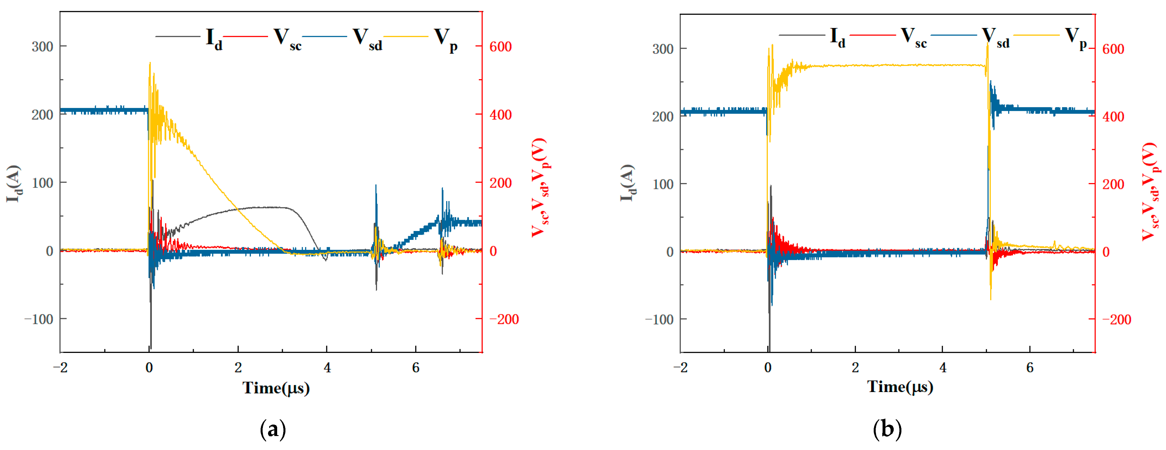
The drain-source voltage Vsd of the discharge switch and the voltage Vp across the protection inductors or diodes were also measured and presented in Figure 9. As in the short-circuit stage in the half-bridge SSMG, the voltage instantly fell on the inductor L1 and decreased gradually to zero with the increase in the through current, as shown in Figure 9a. In the fault stage in the diode protection SSMG as shown in Figure 9b, the voltage fell on the diode Ds1 throughout the discharging process. So, there was no continuous through current. This further proves the successful blocking of through current by these diodes.
5. Conclusions
To improve the reliability of half-bridge SSMGs, we proposed to block the through currents with fast recovery diodes. A 52-stage SSMG prototype was built. Simulation and experiments were carried out to verify its feasibility. Both simulating and experimental results indicated that the fault through current could rise to above 250 A when there was no overcurrent protection. With a 10-μH inductor in each stage, the fault through current dropped to 60 A. With the proposed diodes the fault through current was completely blocked. Furthermore, 22-kV rectangular pulses were also obtained. The introduction of diodes not only reserved the truncation function of charge switches, but also broke the through current loops so the overcurrent risk of switches was reduced. The proposed through current protection with fast recovery diodes helps to block the overcurrent in power cells, which considerably simplifies the design of the overcurrent protection for semiconductor switches. In combination with a proper overcurrent protection in the load loop, it can further improve the reliability of half-bridge SSMGs.
Author Contributions
Conceptualization, P.C. and J.R.; Data curation, P.C.; Formal analysis, P.C., S.J. and J.R.; Funding acquisition, F.S., J.Z. and J.R.; Investigation, P.C. and S.J.; Methodology, P.C.; Project administration, J.Z. and J.R.; Resources, F.S. and J.R.; Software, F.S. and P.C.; Supervision, J.Z. and J.R.; Validation, F.S. and J.R.; Visualization, P.C.; Writing—original draft, P.C.; Writing—review and editing, F.S., P.C., J.Z. and J.R. All authors have read and agreed to the published version of the manuscript.
Funding
This research was funded in part by the National Natural Science Foundation of China (Grant No. 12205192), ‘Hundred Talents Program’ of the ‘Pioneer Initiative’ in Chinese Academy of Sciences (Grant No. Y722171202), Natural Science Foundation of Shandong Province, China, grant number (ZR2022QE168), and The Quancheng 5150 Project.
Data Availability Statement
The data presented in this study are available on request from the corresponding author.
Conflicts of Interest
F.S. and J.Z. were employed by the company Jinan Guoke Medical Technology Development Co., Ltd., Jinan 250000, China. The remaining authors declare that the research was conducted in the absence of any commercial or financial relationships that could be construed as a potential conflict of interest.
References
- Zhong, Z.; Rao, J.; Liu, H.; Redondo, L.M. Review on Solid-State-Based Marx Generators. IEEE Trans. Plasma Sci. 2021, 49, 3625–3643. [Google Scholar] [CrossRef]
- Renau, A. 35 Years of challenge and innovation in ion implant. MRS Adv. 2022, 7, 1234–1240. [Google Scholar] [CrossRef]
- Nguyen, D.K.; Dimitrakellis, P.; Talley, M.R.; O’Dea, R.M.; Epps, T.H., III; Watson, M.P.; Vlachos, D.G. Oxidative Functionalization of Long-Chain Liquid Alkanes by Pulsed Plasma Discharges at Atmospheric Pressure. ACS Sustain. Chem. Eng. 2022, 10, 15749–15759. [Google Scholar] [CrossRef]
- Peng, W.; Cao, Y.; Zhang, Y.; Zhong, A.; Zhang, C.; Wei, Z.; Liu, X.; Dong, S.; Wu, J.; Xue, Y.; et al. Optimal Irreversible Electroporation Combined with Nano-Enabled Immunomodulatory to Boost Systemic Antitumor Immunity. Adv. Healthc. Mater. 2023, e2302549. [Google Scholar] [CrossRef]
- Rao, J.; Zhang, R.; Shi, F.; Zhuang, L.; Ji, Z.; Zhuang, J. A high-voltage solid-state Marx generator with adjustable pulse edges. High Volt. 2023, 8, 878–888. [Google Scholar] [CrossRef]
- Chen, L.; Zhu, C.; Zheng, J.; Qiu, J.; Zhao, H.; Liu, K. A Flexible Solid-State Marx Modulator Module Based on Discrete Magnetic Coupling Drivers. Electronics 2023, 12, 3831. [Google Scholar] [CrossRef]
- Chen, R.; Yang, J.; Cheng, X.; Qian, B. Study on a Marx generator with high-voltage silicon-stacks instead of isolating inductances. High Volt. 2020, 5, 762–767. [Google Scholar] [CrossRef]
- Ma, J.; Yu, L.; Sun, W.; Dong, S.; Gao, L.; Yao, C. Investigation and Evaluation of Solid-State Marx Pulse Generator Based on 3-D Busbar. IEEE Trans. Plasma Sci. 2021, 49, 1597–1604. [Google Scholar] [CrossRef]
- Ding, W.; Wang, Y.; Fan, C.; Gou, Y.; Xu, Z.; Yang, L. A Subnanosecond Jitter Trigger Generator Utilizing Trigatron Switch and Avalanche Transistor Circuit. IEEE Trans. Plasma Sci. 2015, 43, 1054–1062. [Google Scholar] [CrossRef]
- Jo, H.B.; Song, S.H.; Lee, S.H.; Ryoo, H.J. MOSFET Gate Driver Circuit Design for High Repetitive (200 kHz) High Voltage (10 kV) Solid-State Pulsed-Power Modulator. IEEE Trans. Power Electron. 2021, 36, 10461–10469. [Google Scholar] [CrossRef]
- Jiang, W.; Yatsui, K. Compact pulsed power generators for industrial applications. IEEJ Trans. Fundam. Mater. 2004, 124, 451–455. [Google Scholar] [CrossRef]
- Lehr, J.; Ron, P. Marx generators and Marx-like circuits. In Foundations of Pulsed Power Technology; IEEE: New York, NY, USA, 2018; pp. 1–62. [Google Scholar] [CrossRef]
- Bykov, Y.A.; Krastelev, E.G. Gas spark switches with increased operating life for Marx generator of lightning test complex. Phys. At. Nucl. 2016, 79, 1614–1618. [Google Scholar] [CrossRef]
- Zhang, H.; Shu, T.; Liu, S.; Zhang, Z.; Song, L.; Zhang, H. A Compact Modular 5 GW Pulse PFN-Marx Generator for Driving HPM Source. Electronics 2021, 10, 545. [Google Scholar] [CrossRef]
- Krasnykh, A.; Akre, R.; Gold, S.; Koontz, R. A solid state Marx type modulator for driving a TWT. In Proceedings of the Conference Record of the 2000 Twenty-fourth International Power Modulator Symposium, Norfolk, VA, USA, 26–29 June 2000; pp. 209–211. [Google Scholar]
- Rao, J.; Lei, Y.; Jiang, S.; Li, Z.; Kolb, J.F. All solid-state rectangular sub-microsecond pulse generator for water treatment application. IEEE Trans. Plasma Sci. 2018, 46, 3359–3363. [Google Scholar] [CrossRef]
- Chirokov, A.; Gutsol, A.; Fridman, A.; Sieber, K.D.; Grace, J.M.; Robinson, K.S. Analysis of two-dimensional microdischarge distribution in dielectric-barrier discharges. Plasma Sources Sci. Technol. 2004, 13, 623. [Google Scholar] [CrossRef]
- Baek, J.W.; Yoo, D.W.; Rim, G.H.; Lai, J.-S. Solid state Marx generator using series-connected IGBTs. IEEE Trans. Plasma Sci. 2005, 33, 1198–1204. [Google Scholar] [CrossRef]
- Cassel, R.L. An all solid-state pulsed Marx type modulator for magnetrons and klystrons. In Proceedings of the 2005 IEEE Pulsed Power Conference, Monterey, CA, USA, 13–15 June 2007; pp. 836–838. [Google Scholar]
- Horiguchi, T.; Kinouchi, S.I.; Nakayama, Y.; Akagi, H. A fast short-circuit protection method using gate charge characteristics of SiC MOSFETs. In Proceedings of the 2015 IEEE Energy Conversion Congress and Exposition (ECCE), Montreal, QC, Canada, 20–24 September 2015. [Google Scholar]
- Wang, J.; Jiang, X.; Li, Z.; Shen, Z.J. Short-Circuit Ruggedness and Failure Mechanisms of Si/SiC Hybrid Switch. IEEE Trans. Power Electron. 2019, 34, 2771–2780. [Google Scholar] [CrossRef]
- Li, Z.; Liu, H.; Jiang, S.; Rao, J. A novel drive circuit with overcurrent protection for solid state pulse generators. IEEE Trans. Dielectr. Electr. Insul. 2019, 26, 361–366. [Google Scholar] [CrossRef]
- Yuan, S.; Wang, Y.; Li, Z.; Jiang, S.; Zhuang, J.; Rao, J. A Drive Circuit with Overcurrent Protection for Solid-State Marx Generators. IEEE Trans. Plasma Sci. 2022, 50, 2412–2420. [Google Scholar] [CrossRef]
- Liu, K.; Luo, Y.; Qiu, J. A repetitive high voltage pulse adder based on solid state switches. IEEE Trans. Dielectr. Electr. Insul. 2009, 16, 1076–1080. [Google Scholar] [CrossRef]
- Jang, S.R.; Ryoo, H.J.; Goussev, G. Compact and High Repetitive Pulsed Power Modulator Based on Semiconductor Switches. IEEE Trans. Dielectr. Electr. Insul. 2011, 18, 1242–1249. [Google Scholar] [CrossRef]
- Achour, Y.; Starzyński, J.; Rąbkowski, J. Modular Marx Generator Based on SiC-MOSFET Generating Adjustable Rectangular Pulses. Energies 2021, 14, 3492. [Google Scholar] [CrossRef]
- Kpomahou, Y.J.F.; Miwadinou, C.H.; Hinvi, L.A. Mathematical modelling and parametric resonances of a nonlinear RLC series circuit. Int. J. Nonlinear Dyn. Control 2018, 1, 133–153. [Google Scholar] [CrossRef]
- Premkumar, M.; Kumar, C.; Sowmya, R. Analysis and Implementation of High-Performance DC-DC Step-Up Converter for Multilevel Boost Structure. Front. Energy Res. 2019, 7, 149. [Google Scholar] [CrossRef]
- Zhang, C.; Jin, S.; Fang, Z. Research on the Overcurrent-Short Circuit Protection Method of Nanosecond Pulse Power Supply Applied in the Field of Gliding Arc Discharge. In Proceedings of the 2021 IEEE International Conference on Plasma Science (ICOPS), Lake Tahoe, NV, USA, 12–16 September 2021; p. 1. [Google Scholar] [CrossRef]
Figure 1.
Several common Marx circuit topologies. (a) Classic Marx generator topology. (b) Positive SSMG based on half-bridge structure. (c) Positive SSMG with diodes and inductors in charging loops. (d) Positive SSMG with inductor protection structure.
Figure 1.
Several common Marx circuit topologies. (a) Classic Marx generator topology. (b) Positive SSMG based on half-bridge structure. (c) Positive SSMG with diodes and inductors in charging loops. (d) Positive SSMG with inductor protection structure.
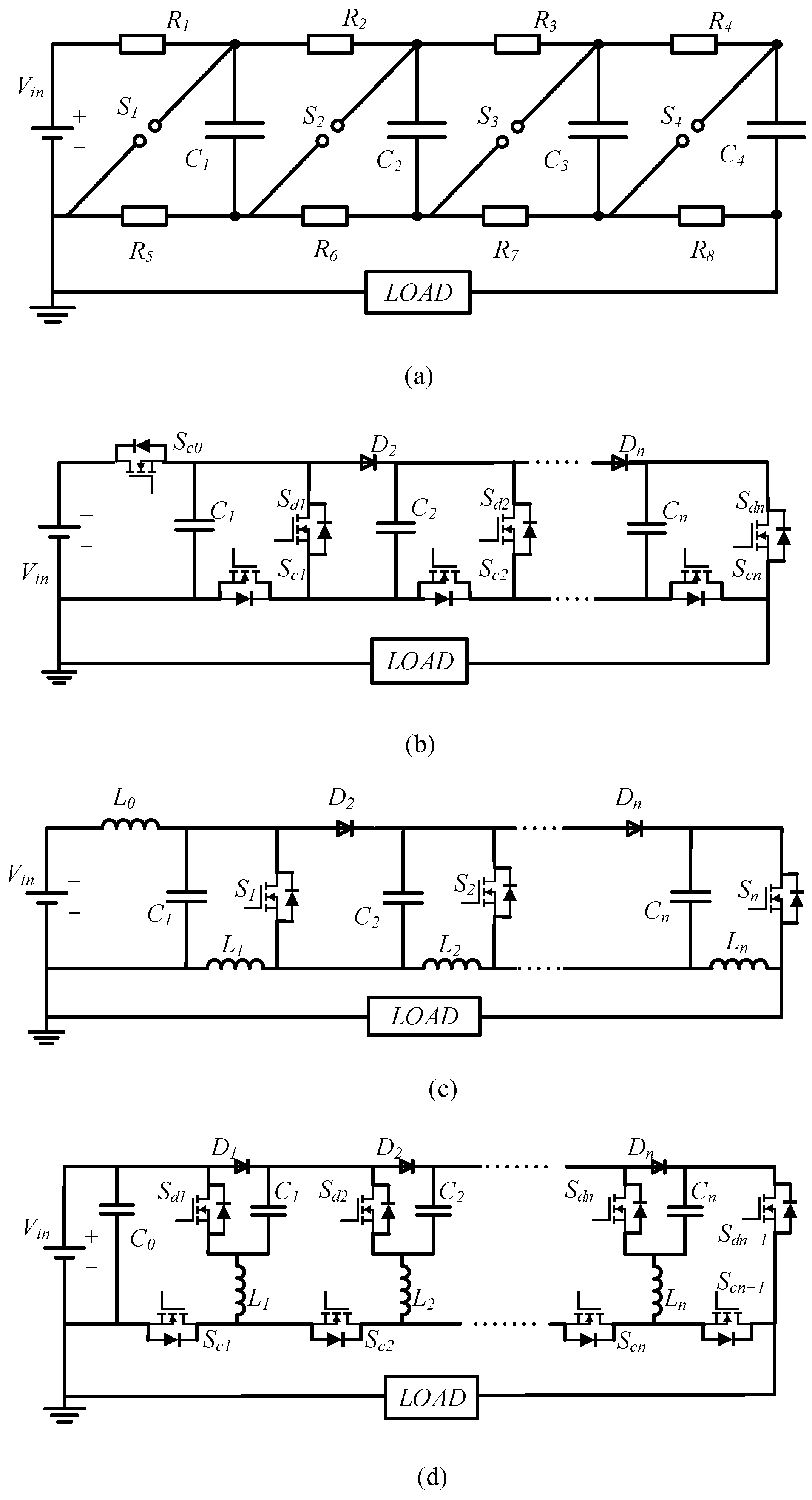
Figure 2.
The structure of the diode protection SSMG and its operating principle. (a) Charge phase (truncation phase). (b) Discharge phase. (c) Partial short-circuit (charge phase).
Figure 2.
The structure of the diode protection SSMG and its operating principle. (a) Charge phase (truncation phase). (b) Discharge phase. (c) Partial short-circuit (charge phase).
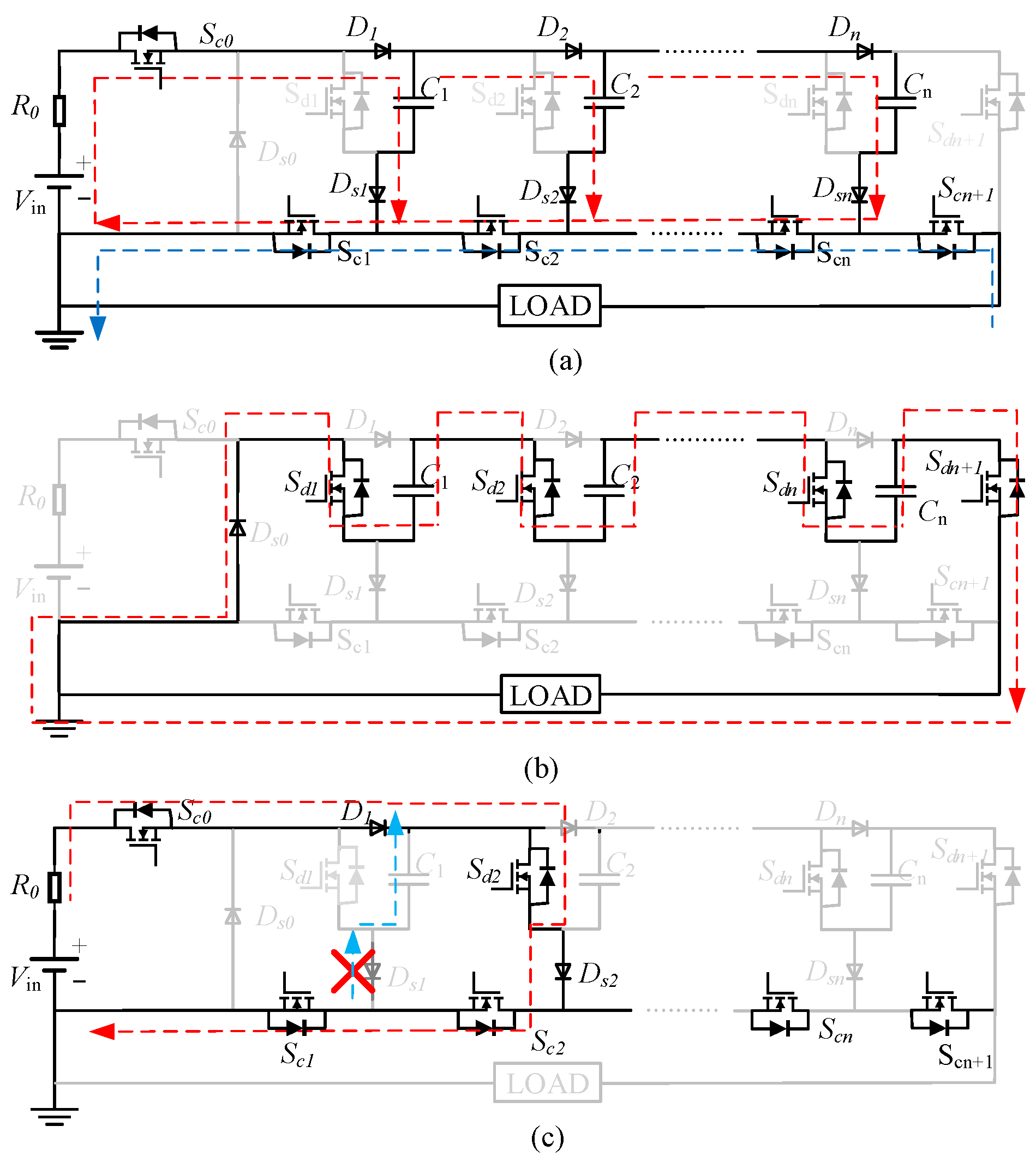
Figure 3.
Through current loop in three basic power cells using half-bridge SSMG (a), inductor protection SSMG (b) and diode protection SSMG (c) when charging and discharge switches are on simultaneously.
Figure 3.
Through current loop in three basic power cells using half-bridge SSMG (a), inductor protection SSMG (b) and diode protection SSMG (c) when charging and discharge switches are on simultaneously.

Figure 4.
Two possible faults that might occur in proposed SSMG. (a) Possible through current loop including Ds0. (b) Possible overvoltage over Ds1 and Sc1.
Figure 4.
Two possible faults that might occur in proposed SSMG. (a) Possible through current loop including Ds0. (b) Possible overvoltage over Ds1 and Sc1.
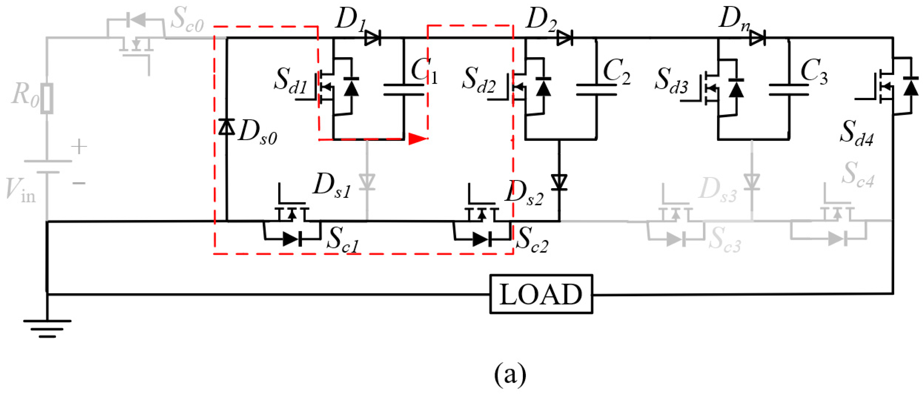
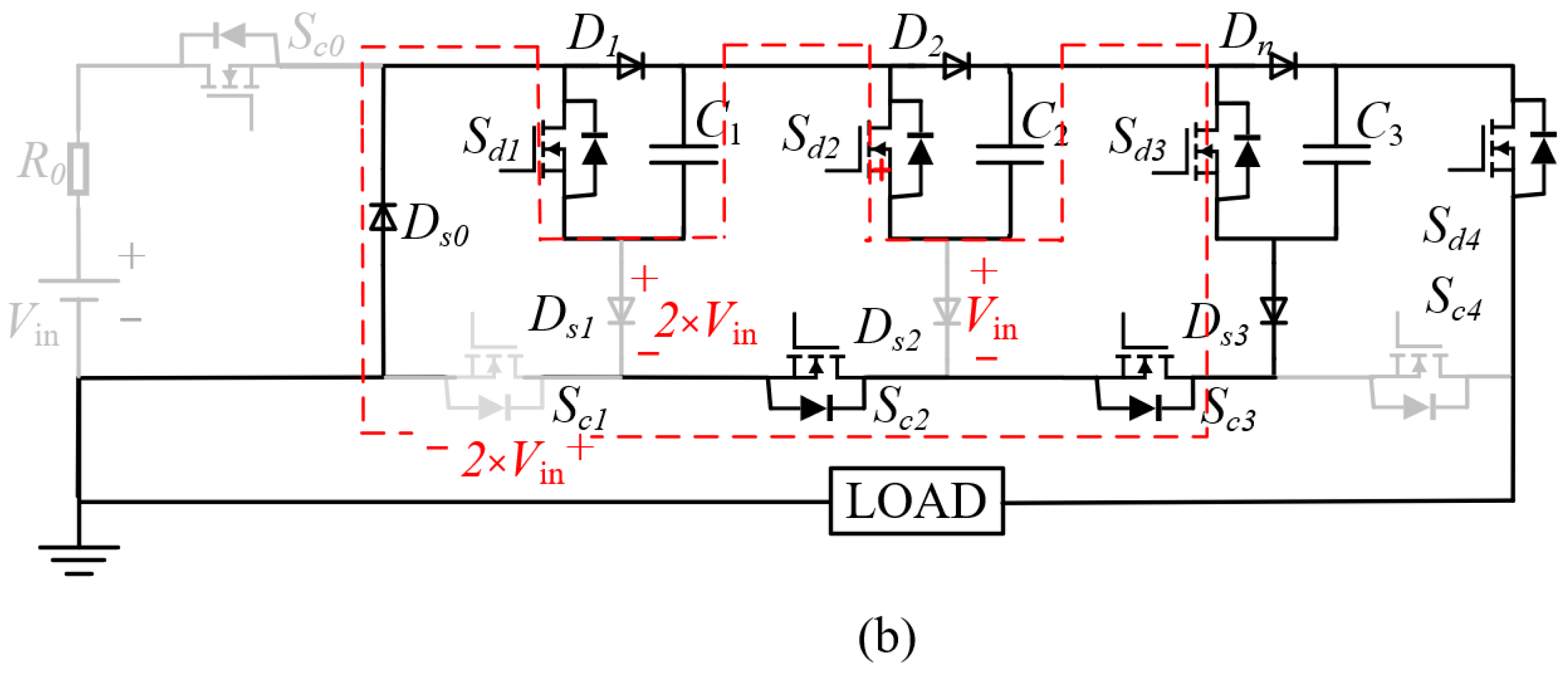
Figure 5.
Schematic diagram of the local short-circuit and the location of the physical quantities under test.
Figure 5.
Schematic diagram of the local short-circuit and the location of the physical quantities under test.
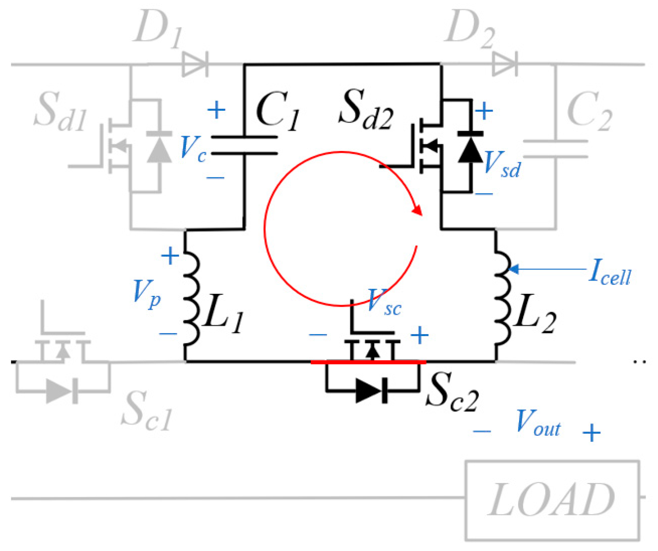
Figure 6.
Partial current, capacitor voltage, and pulse output waveforms of three circuit topologies under fault conditions. (a) Normal operation of half-bridge SSMG. (b) Half-bridge SSMG. (c) Inductor protection SSMG. (d) Diode protection SSMG.
Figure 6.
Partial current, capacitor voltage, and pulse output waveforms of three circuit topologies under fault conditions. (a) Normal operation of half-bridge SSMG. (b) Half-bridge SSMG. (c) Inductor protection SSMG. (d) Diode protection SSMG.

Figure 7.
Photograph of developed diode protection SSMG.

Figure 8.
Experimental waveforms of Icell, Vout, and Vc in the normal or fault stage in different circuits. (a) Normal operation of half-bridge SSMG. (b) Fault stage of half-bridge SSMG. (c) Fault stage of inductor protection SSMG. (d) Fault stage of diode protection SSMG.
Figure 8.
Experimental waveforms of Icell, Vout, and Vc in the normal or fault stage in different circuits. (a) Normal operation of half-bridge SSMG. (b) Fault stage of half-bridge SSMG. (c) Fault stage of inductor protection SSMG. (d) Fault stage of diode protection SSMG.
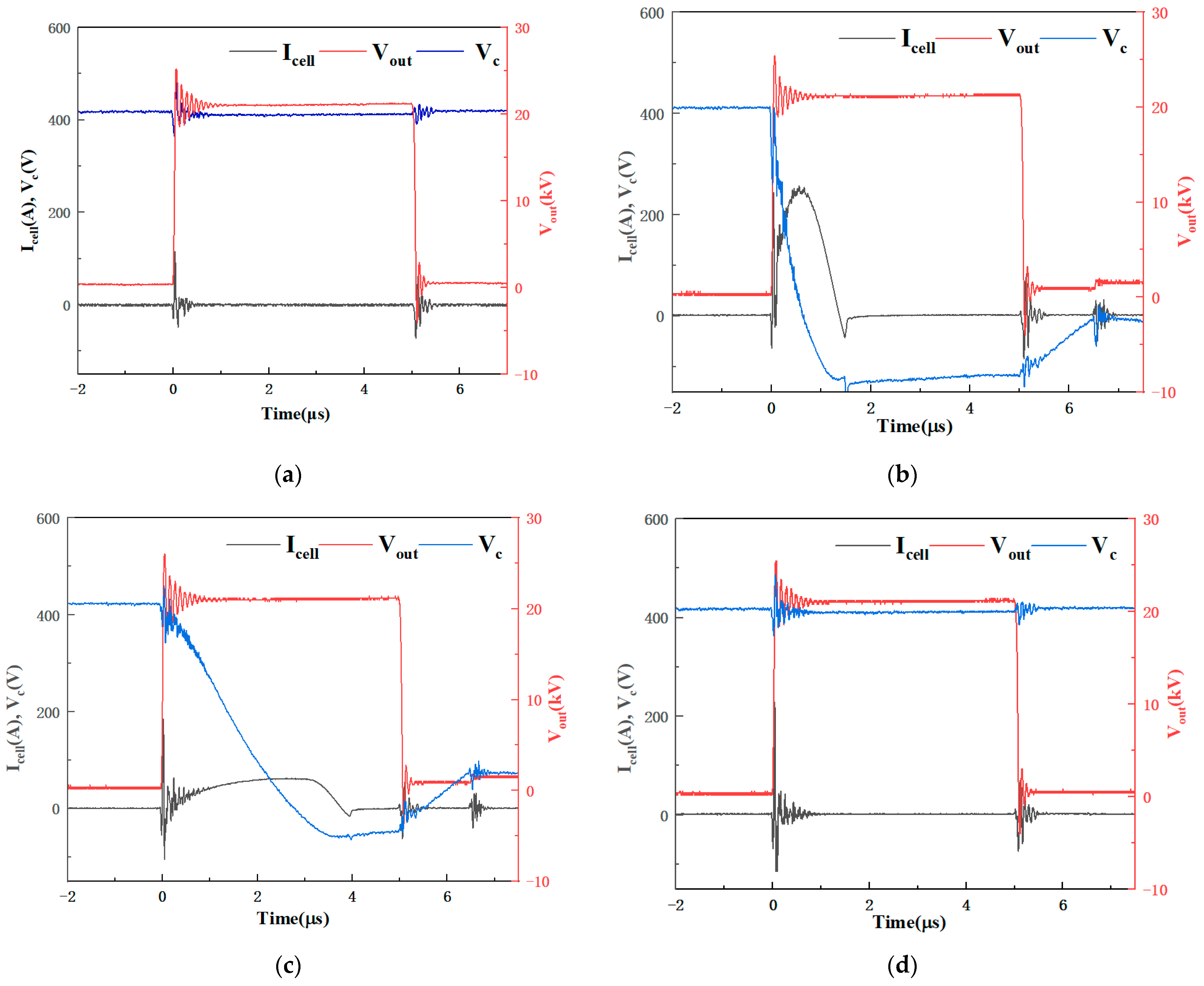
Figure 9.
Experimental waveforms of Vsd and Vp in the fault stage in different circuits. (a) Inductor protection SSMG. (b) Diode protection SSMG.
Figure 9.
Experimental waveforms of Vsd and Vp in the fault stage in different circuits. (a) Inductor protection SSMG. (b) Diode protection SSMG.

Table 1.
Specifications of C2M0080120D.
| Contents | Value |
|---|---|
| Drain-Source Voltage Vds | 1200 V |
| Continuous Drain Current Id | 31.6 A |
| Pulsed Drain Current | 80 A |
| On-Resistance Rds(on) | 80 mΩ |
Table 2.
Specifications of FR157.
| Contents | Value |
|---|---|
| Repetitive Peak Voltage VRRM | 1 kV |
| Average Forward Current IF(AV) | 1.5 A |
| Surge Forward Current IFSM | 60 A |
| Peak Reverse Current IRRM | 50 μA |
| Reverse Recovery Time trr | 500 ns |
Table 3.
Specifications of the Simulated SSMG.
| Contents | Value |
|---|---|
| Input Voltage | 420 V |
| Stages | 3 |
| Output Voltage | 1260 V |
| Storage Capacitor | 400 nF |
| Load | 3 pF |
| Pulse Width | 5 μs |
| Protection Inductor | 10 μH |
Table 4.
Specifications of the developed SSMG.
| Contents | Value |
|---|---|
| Input Voltage | 0–420 V |
| Stages | 52 |
| Output Voltage | 0–22 kV |
| Pulse Width | 1–50 μs |
| Load | 3 pF (Probe) |
| Storage Capacitor | 400 nF |
Disclaimer/Publisher’s Note: The statements, opinions and data contained in all publications are solely those of the individual author(s) and contributor(s) and not of MDPI and/or the editor(s). MDPI and/or the editor(s) disclaim responsibility for any injury to people or property resulting from any ideas, methods, instructions or products referred to in the content. |
© 2023 by the authors. Licensee MDPI, Basel, Switzerland. This article is an open access article distributed under the terms and conditions of the Creative Commons Attribution (CC BY) license (https://creativecommons.org/licenses/by/4.0/).
Share and Cite
MDPI and ACS Style
Shi, F.; Chen, P.; Jiang, S.; Zhuang, J.; Rao, J. A Solid-State Marx Generator with Prevention of through Current for Rectangular Pulses. Electronics 2024, 13, 101. https://doi.org/10.3390/electronics13010101
AMA Style
Shi F, Chen P, Jiang S, Zhuang J, Rao J. A Solid-State Marx Generator with Prevention of through Current for Rectangular Pulses. Electronics. 2024; 13(1):101. https://doi.org/10.3390/electronics13010101
Chicago/Turabian StyleShi, Fukun, Ping Chen, Song Jiang, Jie Zhuang, and Junfeng Rao. 2024. "A Solid-State Marx Generator with Prevention of through Current for Rectangular Pulses" Electronics 13, no. 1: 101. https://doi.org/10.3390/electronics13010101
Note that from the first issue of 2016, this journal uses article numbers instead of page numbers. See further details here.