Article

A Current Differential Protection Scheme for Distribution Networks with Inverter-Interfaced Distributed Generators Considering Delay Behaviors of Sequence Component Extractors

1
School of Electric Power Engineering, South China University of Technology, Guangzhou 510641, China
2
Electric Power Research Institute, China Southern Power Grid, Guangzhou 510663, China
3
Guangzhou Electric Power Design Institute, China Southern Power Grid, Guangzhou 510630, China
*
Author to whom correspondence should be addressed.
Electronics 2023, 12(23), 4727; https://doi.org/10.3390/electronics12234727
Submission received: 8 October 2023 / Revised: 9 November 2023 / Accepted: 16 November 2023 / Published: 21 November 2023

Abstract

:
The high-level proliferation of inverter-interfaced distributed generators (IIDGs) in modern distribution networks (DNs) has changed system topologies and fault current signatures, which compromises the protective relays in DNs. Investigating IIDG fault behaviors-based protection scheme will benefit the grid’s safety and stability. This paper proposes a novel current differential protection (CDP) scheme that considers the delay behaviors of positive- and negative-sequence component extractors for IIDGs in DNs. A frequency-domain analytical model of the fault current for a grid-connected IIDG with the PQ control strategy and a low-voltage ride-through (LVRT) capability is investigated. The dynamic behavior of the IIDGs considering the sequence-component extractor based on the Pade approximation is presented, where the T/4 delay extractor of the IIDGs causes a two-stage behavior in the fault transient process. It is found that a 5 ms error between the measured and actual values after the fault will affect the transient characteristics of the IIDGs. The transient current generated by the IIDGs during grid faults contains a large number of low-order harmonic components within the range of 0–200 Hz, which is significantly different to the current provided by the power grid. Therefore, the proposed CDP scheme uses protective relays at both terminals to obtain the required transient electric quantity using the Prony method. By constructing the frequency-characteristics ratio (FCR) and the exchanging FCR between two terminal relays, the developed protection criteria are implemented. The accuracy of the fault analysis method, whose maximum computational error is below 0.1%, and the feasibility of the proposed protection scheme are demonstrated by using a 10 kV DN in a PSCAD/EMTDC simulation, which can be applied to various fault conditions and traditional DNs without IIDGs.

1. Introduction

1.1. Background and Motivation

Distribution networks (DNs) are the essential link between transmission systems and electricity users. With the increase in electricity demands and the development of power grids, it is essential that modern DNs can accurately and reliably isolate the faulty sections. An applicable protection relay ensures the secure and stable operation of modern DNs, which can prevent damage to the equipment and minimize power outages over a widespread area.
Renewable clean energy plays a crucial role in alleviating the energy crisis and improving the environment. An increasing variety of distributed generations (DGs) are being incorporated into modern medium-voltage DNs. The high-level proliferation of DGs, especially inverter-interfaced distributed generators (IIDGs), enables the DNs to be green and sustainable [1,2]. However, grid-connected IIDGs that are significantly different to the traditional synchronous generators [3,4,5] dramatically exacerbate the complexity of the grid operation and fault levels [6,7], which change the topologies and fault characteristics of the DNs. The large-scale deployment of IIDGs undoubtedly challenges the selectivity and sensitivity of the existing protective devices of DNs. In addition, the fault analysis and feature extraction of DNs are the theoretical basis for the construction of the protection methodology. Each change in the DN would require a change in fault analysis and relay protection. Hence, exploring the protection scheme according to the fault analysis of IIDG behaviors to enhance the DN’s safety and stability is highly demanded.

1.2. State of the Art

The current characteristics have been utilized to construct overcurrent protection (OCP) schemes in recent decades [8]. An OCP approach based on negative- and zero-sequence currents is provided for multi-phase faults that occur in traditional DNs without IIDGs [9]. The authors of [10] present an adaptive OCP method by using local information and the Thevenin equivalent circuit of DNs, without extra infrastructure. The OCP techniques can automatically adjust the protection settings to meet the relay-tripping requirements based on different current characteristics and the effects of the IIDGs in DNs [11,12]. The authors of [13] studied an IIDG mitigation strategy to eliminate the protection blindness of the OCP of DNs without the installation of new relays. An adaptive OCP criterion was investigated through the MMS service for DNs with the PQ-IIDG [14]. Furthermore, the IIDGs will aggravate the protection coordination of overcurrent relays in DNs [15,16,17]. There is a challenge in determining the direction of fault currents for the overcurrent relays that generally employ nondirectional types of DNs [18]. The directional elements also fail to run properly under the influence of the inverter control of IIDGs [19]. Therefore, the above OCP schemes or other improvements may not be suitable for DNs with the high-level proliferation of IIDGs.
Current differential protection (CDP) seems to be the preferred choice for modern DNs in the presence of IIDGs due to its sufficient selectivity, higher sensitivity and various applications for communication [20,21,22]. A positive-sequence component-based CDP scheme is suggested by using data self-synchronization and communication techniques for DNs combined with IIDGs [23]. A time-graded CDP method is proposed to achieve the coordination effectively, with lateral protection devices in the post-fault DN topology [24]. CDP approaches with improved fault data self-synchronization are proposed in radial DNs with IIDGs [25,26]. A virtual multi-terminal CDP methodology is implemented via the simultaneous exchange of remote and local currents [27]. The authors of [28] provide a differential protection criterion based on impedance differences during normal operation and the internal/external faults of DNs. The sensitivity of the traditional CDP can be improved by changing the restraint area of the protection criteria [29]; however, the dual-end data synchronization issue is ignored. The authors of [30,31] propose a positive-sequence current-based CDP criterion for low-cost communication. Several amplitude-based CDP methods are presented for the DNs to improve the flexibility of IIDG integration [32,33,34]. Moreover, abrupt changes in the electrical quantities during faults involve a wealth of transient information. A differential protection scheme is presented based on a high-frequency impedance model for the IIDG-contained DN [35]. Combined with phasor-based protection, the transient current polarity is selected for fault identification to eliminate the coordination delays of relays in DNs with IIDGs [36], which are incapable of adapting to the negative influence of the inverter control of IIDGs.
It is worth noting that IIDGs commonly use T/4 delay extractors to split positive- and negative-sequence components, which leads to delay behaviors and measurement errors during the fault transient stage [11,27,37]. Positive- and negative-sequence components of the point of common coupling (PCC) voltage and current measured by the control system are inconsistent with instantaneous components of IIDGs with a delay dynamic. Measurement errors caused by T/4 delay behaviors will affect the fault current characteristics of IIDGs and grids. The fault transient current of DNs with IIDGs is a nonlinear, time-varying, wide-frequency signal, involving a large number of harmonic components. However, the above protection methods do not consider the dynamic characteristics of T/4 delay behaviors. The impact of measurement errors in the positive- and negative-sequence components on the IIDG transient current is also neglected.

1.3. Scope and Main Contributions

This article addresses the above problems regarding the fault transient analysis and protection principle of DNs with IIDGs to guarantee the secure and reliable operation of power systems. The objective of this article consists of developing the frequency-domain analytical model for calculating the fault current of a grid-connected PQ-IIDG and investigating the delay behaviors of IIDGs considering the T/4 sequence-component extractor. Furthermore, by fully understanding the frequency characteristics of a 5 ms two-stage behavior of IIDGs, a novel CDP scheme for DNs with IIDGs considering T/4 delay behaviors is proposed, which can enhance the sensitivity and selectivity of the protection relay.
This paper presents an accurate fault analysis and calculation model for IIDGs compared to existing methods [38,39,40], and at the same time, makes the protection robust and reliable. This method allows for the installation of the IIDG in any location within the protected area and bus, which is applicable to different fault types, fault locations and fault resistances, with good generality. Furthermore, the protection principle can be performed via the existing communication channel at both terminals, without extra channels to collect the local information of each IIDG. Additionally, protective relays can be operated correctly for a traditional DN without IIDGs.

1.4. Structure of the Paper

The remainder of this paper is organized as follows. Section 2 describes the dynamic process of the T/4 delay behaviors and its effect on the fault transient current of IIDGs. The amplitude-frequency characteristics of the fault transient current of the IIDG are also obtained. Section 3 proposes a CDP scheme based on the frequency-characteristics ratio (FCR). Section 4 tests the effectiveness of the proposed protection scheme in the PSCAD/EMTDC simulation platform. The discussion section is presented in Section 5. Finally, Section 6 summarizes this paper.

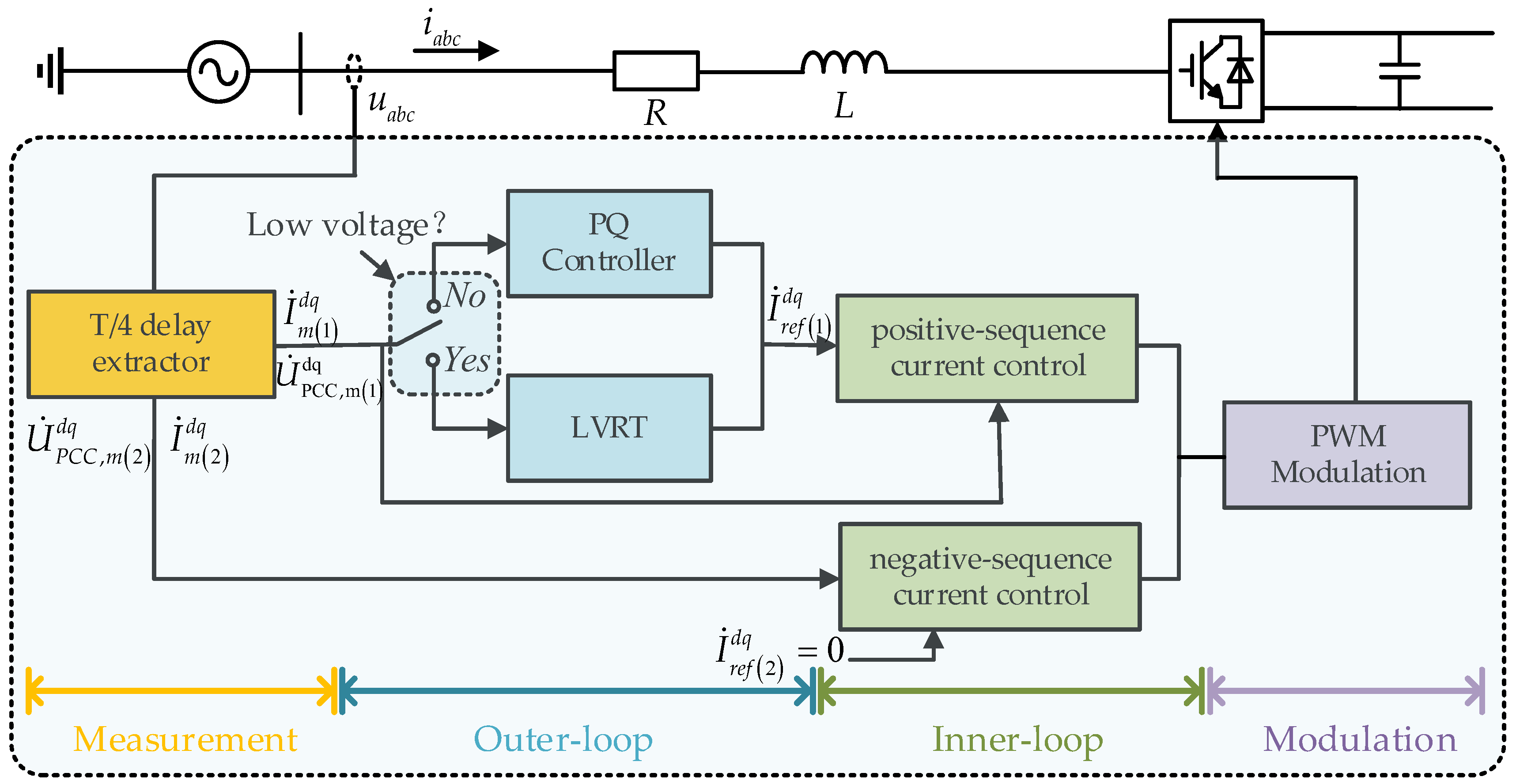
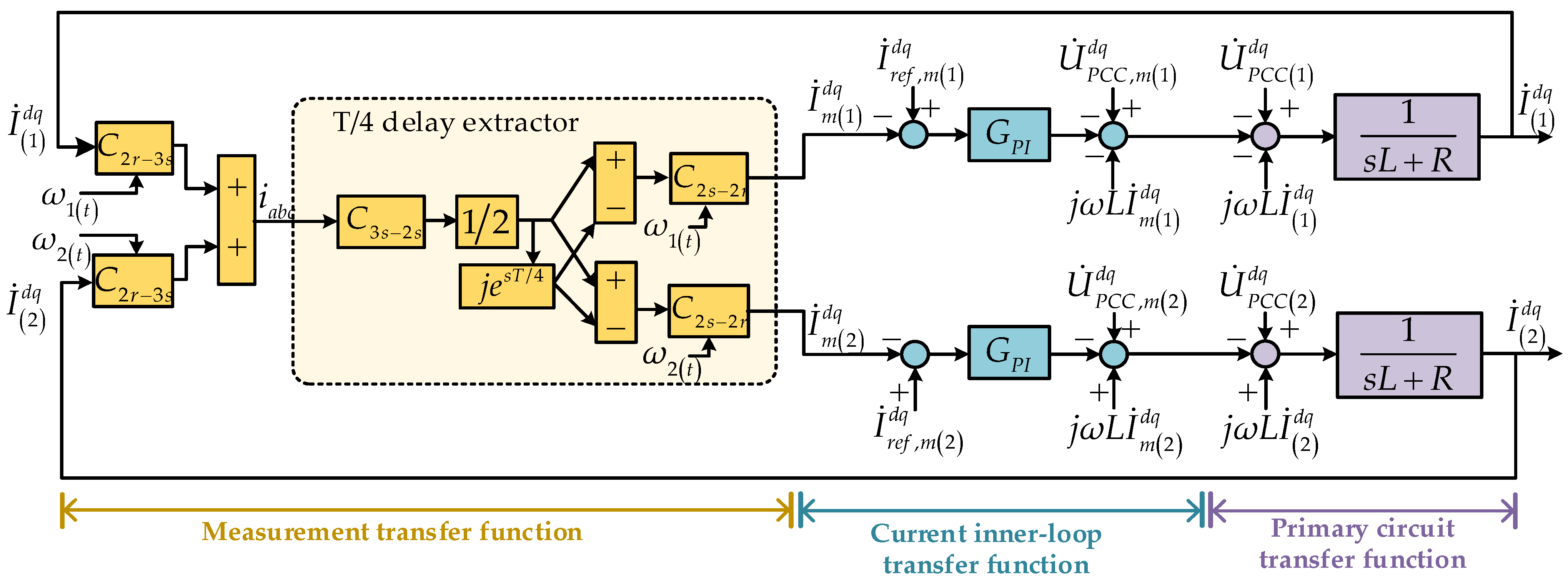
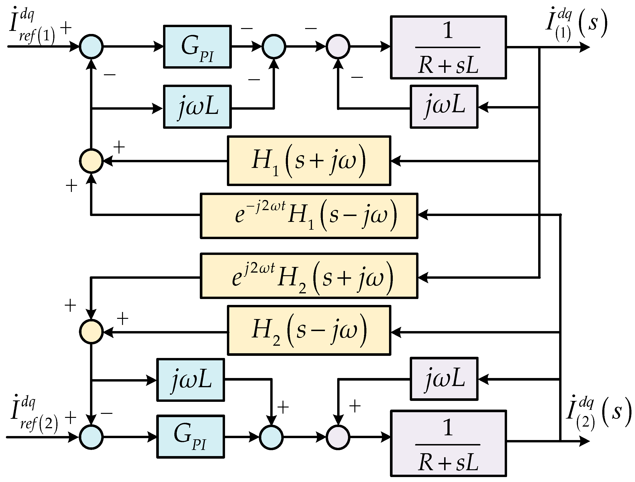
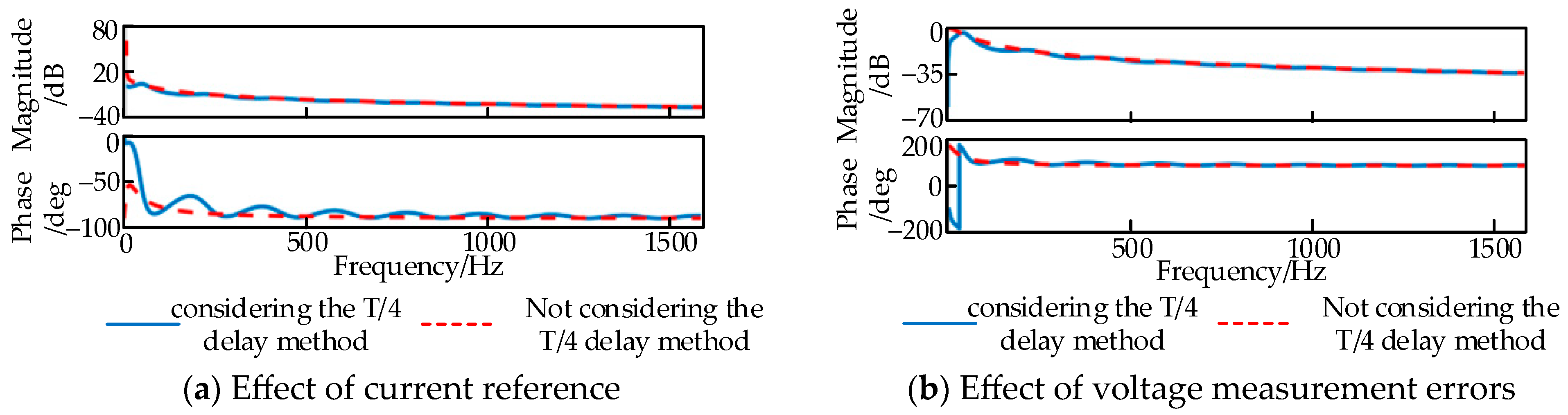
2. Fault Transient Analysis of IIDGs Considering T/4 Delay Behaviors
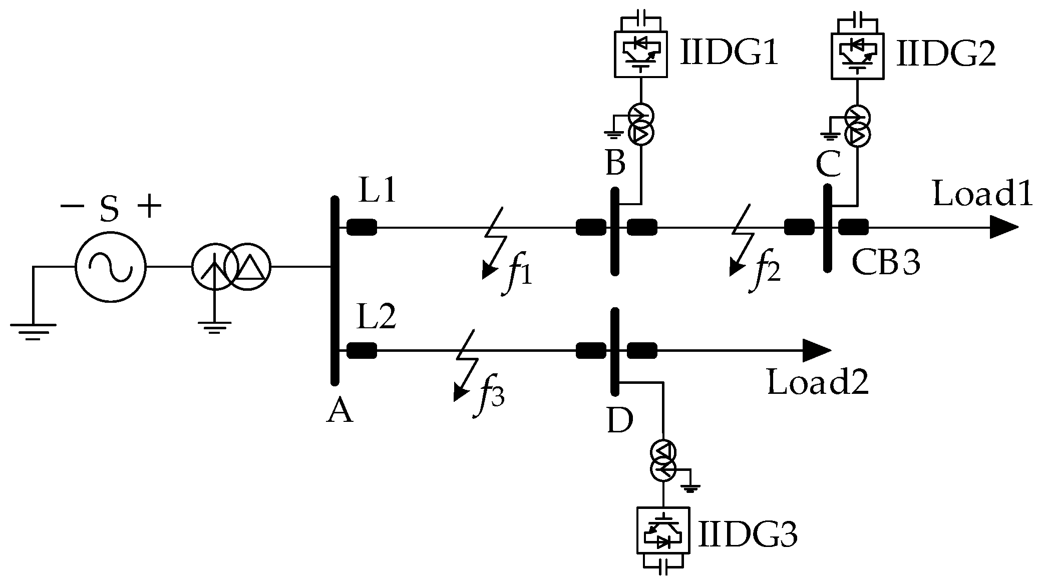
2.1. Fault Model

The typical control configuration of a grid-connected IIDG is shown in Figure 1. The closed-loop control system mainly consists of the measurement, outer-loop, inner-loop and modulation, where u a b c is the three-phase voltage at the point of common coupling (PCC); i a b c is the IIDG output current; L and R are the equivalent inductance and resistance, respectively; U ˙ is the vector of PCC voltage, I ˙ is the vector of IIDG current output in the dq coordinate system; the superscripts d and q are the d-axis and q-axis in the rotating reference frame; the subscripts m and ref denote the measured and reference values; and the subscripts (1) and (2) represent the positive- and negative-sequence components.
During the measurement process shown in Figure 1, three-phase voltages u a b c and currents i a b c are split using a T/4 delay extractor to obtain relevant positive- and negative-sequence components. To enable decoupled control, the extracted positive- and negative-sequence voltages and currents are mapped to the dq coordinate system, respectively. The outer-loop consists of the PQ controller and a low-voltage ride-through (LVRT) control strategy, which generates reference currents I ˙ r e f 1 d q based on the voltage detected at PCCs. The inner-loop controls positive- and negative-sequence currents using the proportional-integral (PI) controller to track their reference values. Based on the pulse width-modulated (PWM) modulation, the reference voltages obtained from the inner-loop are converted into triggering pulses to control the power electronic devices.
Considering the dynamic characteristics of the T/4 delay sequence component extractor from the measurement shown in Figure 1, the relationship between the measured and actual values of the PCC voltage ( U ˙ P C C , m d q and U ˙ P C C d q ) is as follows:
U ˙ P C C , m 1 d q = H 1 s + j ω U ˙ P C C 1 d q + e j 2 ω t H 1 s j ω U ˙ P C C 2 d q U ˙ P C C , m 2 d q = e j 2 ω t H 2 s + j ω U ˙ P C C 1 d q + H 2 s j ω U ˙ P C C 2 d q
where s is the Laplace operator; ω is the angular frequency; and H 1 and H 2 are the transfer functions of the positive- and negative-sequence components that consider the T/4 delay behaviors, respectively, which can be given as:
H 1 = 1 2 1 + j e s T / 4 H 2 = 1 2 1 j e s T / 4
From (1) and (2), the voltage measurement errors of the PCC Δ U ˙ PCC caused by the T/4 delay behavior can be expressed as:
Δ U ˙ P C C 1 = H 1 s + j ω 1 U ˙ P C C 1 d q + e j 2 ω t H 2 ( s j ω ) U ˙ P C C 2 d q Δ U ˙ P C C ( 2 ) = H 2 s j ω 21 U ˙ P C C 2 d q + e j 2 ω t H 2 s + j ω U ˙ P C C 1 d q
From (1)–(3) and Figure 1, the positive- and negative-sequence components can be accurately separated and measured using the sequence component extractor with T/4 delay behavior in the steady state of the IIDGs (i.e., U ˙ P C C , m 1 d q = U ˙ P C C 1 d q , U ˙ P C C , m 2 d q = U ˙ P C C 2 d q ). However, since the outer loop and inner loop use positive- and negative-sequence components of measured voltages and currents as feedback inputs, a measurement error Δ U ˙ P C C that is affected by couplings between the positive- and negative-sequence components in the transient process will profoundly affect the fault current characteristics of IIDGs.
Combined with the T/4 delay extractor, LVRT strategy, inner-loop control of positive- and negative-sequence currents and modulation shown in Figure 1, a transfer function diagram of fault currents of IIDGs considering the T/4 delay behaviors is shown in Figure 2, where C represents the transformation among different coordinate systems; the subscript 2r, 3 s and 2 s are the rotating coordinate system (dq-axis), natural coordinate system (abc-axis) and stationary coordinate system (αβ-axis), respectively; G P I = K P + K I / s is the transfer function of the PI controller; and K P and K I are the proportional and integral gains of the PI controller, respectively. In Figure 2, the measurement transfer function involves coordinate transformations and separations of positive- and negative-sequence currents using the T/4 delay extractor. The reference voltages calculated by difference currents via the PI controller in the current inner-loop transfer function are fed into the primary circuits, which can obtain the actual positive- and negative-currents of the IIDGs.
From Figure 2, it can be seen that the transfer function of IIDG fault currents is composed of the positive- and negative-sequence current extractor, the current inner-loop and the primary topology of the grid-connected converter. It is worth noting that the positive- and negative-sequence currents are independent at the inner loop and primary topology, while there is coupling between the positive- and negative-sequence components in the measurement with the T/4 delay extractor. Therefore, the fault current of a grid-connected IIDG considering the T/4 delay behaviors is:
I ˙ 1 d q = 1 s L + R I ˙ r e f , m 1 d q I ˙ m 1 d q G P I + U ˙ P C C , 1 d q U ˙ P C C , m 1 d q + j ω L I ˙ m 1 d q j ω L I ˙ 1 d q I ˙ 2 d q = 1 s L + R I ˙ r e f , m 2 d q I ˙ m 2 d q G P I + U ˙ P C C , 2 d q U ˙ P C C , m 2 d q j ω L I ˙ m 2 d q + j ω L I ˙ 2 d q

2.2. Fault Characteristics

According to (1)–(4) and the transfer function shown in Figure 2, the irrational functions H 1 and H 2 that contain the delay e s T / 4 , cannot be directly used in the fault analysis. In this regard, the delay in (2), based on the Pade approximation method [41], can be expressed as:
e s T d = i = 0 n 1 n T d s i i ! 2 i i = 0 n T d s i i ! 2 i
where delay duration T d is 5 ms, and n is the number of approximate orders, which is equal to 30 in this paper.
Based on (1)–(5), the unit step response of the measured positive- and negative-sequence components of PCC voltages U ˙ P C C , m d q , the actual value with T/4 delay behaviors U ˙ P C C , T , and the actual value ignoring the T/4 delay behaviors U ˙ P C C , N T , are shown in Figure 3, where the measured positive-sequence voltage in the q-axis U ˙ P C C 1 q that is not affected by that in the d-axis voltage U ˙ P C C 1 d remains 0.
It is clear from Figure 3a,b that Δ U ˙ P C C 1 d and Δ U ˙ P C C 2 d q are 0 during the IIDG steady state, that is, U ˙ P C C , m d can track U ˙ P C C d in real-time. However, there are measurement errors, Δ U ˙ P C C 1 d and Δ U ˙ P C C 2 d q , in the transient process. The delay behavior in which U ˙ P C C , m 1 d increases to U ˙ P C C 1 d after the unit step responses will remain at 5 ms for the positive-sequence measurement. The second-order harmonic components dominate the transient coupling between the positive- and negative-sequence components caused by the T/4 delay extractor. U ˙ P C C , m 2 d q also has a 5 ms delay behavior with a transient error whose magnitude is 0.5 U ˙ P C C , m 2 d q for the negative-sequence measurement.
Moreover, the reference negative-sequence current I ˙ r e f 2 d q in the current inner loop shown in Figure 2 is zero to eliminate its negative impact. The reference positive-sequence current I ˙ r e f 1 d q is generated by U ˙ P C C , m 1 d q based on the LVRT strategy. Δ U ˙ P C C d q will affect the I ˙ r e f 1 d q , which causes the two-stage behavior in the fault transient process. It is clear that the reference current and measurement errors of voltages and currents affect the fault characteristics of IIDGs. For a better understanding of the above effects on the fault transient currents of IIDGs, based on (1), (2), (4) and Figure 2, a transfer function diagram of reference currents to actual currents can be obtained (i.e., the process from the current inner loop transfer function to the primary circuit transfer function in Figure 2), as shown in Figure 4.
From Figure 4, the actual positive- and negative-sequence currents affected by the reference current are expressed as:
I ˙ 1 d q s = I ˙ r e f 1 d q s G P I N 1 s G P I H 1 s j ω + G R L j ω L 1 H 2 s j ω +   I ˙ r e f 2 d q s G P I N 1 s G P I + j ω L e j 2 ω 1 t H 1 s j ω I ˙ 2 d q s = I ˙ r e f 2 d q s G P I N 2 ( s ) G R L s + G P I s H 1 ( s + j ω ) + j ω L 1 H 1 s + j ω +   I ˙ r e f 1 d q s G P I N 1 s G P I j ω L e j 2 ω 1 t H 2 s + j ω
subject to:
G R L = s L + R N 1 s = G R L + G P I H 1   s + j ω 2 + ω 2 L 2 1 H 1   s + j ω 2 +   j ω L G P I s + j 2 ω j ω L G P I H 1   s + j ω H 2   s + j ω N 2 s = G R L + G P I H 2   s j ω 2 + ω 2 L 2 1 H 2   s j ω 2 +   j ω L G P I s j 2 ω j ω L G P I H 2   s j ω H 1   s j ω
As is shown in (6) and (7), the transfer functions of actual currents consist of a post-fault steady-state component and a transient-state decay component. The amplitude-frequency and phase-frequency transfer function characteristics of the IIDG output current in (6) are shown in Figure 5a. In Figure 5a, the amplitude-frequency and phase-frequency characteristics of the current inner-loop transfer function show pulsating waveforms with a period of 200 Hz when the reference current value is perturbed by the T/4 delay behaviors. Response characteristics with and without the T/4 delay behaviors are almost the same for high-order harmonic components above 500 Hz, which indicates that the T/4 delay behaviors do not significantly affect medium-order and high-order harmonic components. However, their fault response characteristics are quite different in the interval of 0–200 Hz. The low-order harmonic components of the IIDG fault current are higher due to the delay behaviors of the sequence-component extractor, which will have a greater impact on the transient characteristics of the IIDG fault current.
In addition, the voltage measurement error Δ U ˙ P C C d q will affect the feedforward of the grid-side voltage in the current inner loop shown in Figure 5a. The difference between measured and actual voltages is large within the 5 ms after the fault occurs, where the voltage feedforward in the inner loop cannot match the actual value. It will inevitably cause an abrupt change for each sequence component current of IIDGs, which is not an active response of the control system to the fault condition. The more severe the fault, the greater the change in the voltages and currents will be. The effect of the current measurement error is similar to the voltage measurement error.
Similarly, the amplitude-frequency and phase-frequency characteristic of the transfer function of the output current of the IIDG under the influence of the voltage measurement error are shown in Figure 5b. As can be seen from Figure 5b, the transfer function of the current inner loop of IIDGs affected by the voltage measurement error still exhibits a pulsating waveform with a period of 200 Hz when the delay behaviors of the sequence component extractor are considered. By comparing Figure 5a,b, it can be seen that the voltage measurement error has a small effect on the amplitude-frequency and phase-frequency characteristics.
It can be concluded that the T/4 delay sequence component extractor will contribute to the two-stage behavior in the fault transient process of IIDGs. In stage I, the T/4 delay behaviors cause measurement errors between measured and actual voltage/current (i.e., U ˙ P C C , m d q and I ˙ m d q ) in the inner-loop controller. The transient components of PCC voltages and currents are affected by reference currents determined by the LVRT strategy, the voltage measurement error, and the current measurement error, which will remain 5 ms. In stage II, the voltage and current measurement errors are zero and the measured values can track the actual values in real time. The transient components of PCC voltages and currents are only affected by the changed reference current and gradually decrease to 0, that is, the IIDG is a fault steady-state process and unaffected by the T/4 delay behavior.

3. Proposed Protection Scheme

When a fault occurs in DNs with IIDGs, the fault current supplied by IIDGs contains a large number of low-order harmonic components, where the second-order harmonic is a dominant component, while the power-frequency component is the dominant component in low-frequency components for the short-circuit current contributed by the system source. Hence, low-order harmonic components caused by T/4 delay behaviors of IIDGs can be used in the protection scheme proposed in this paper.

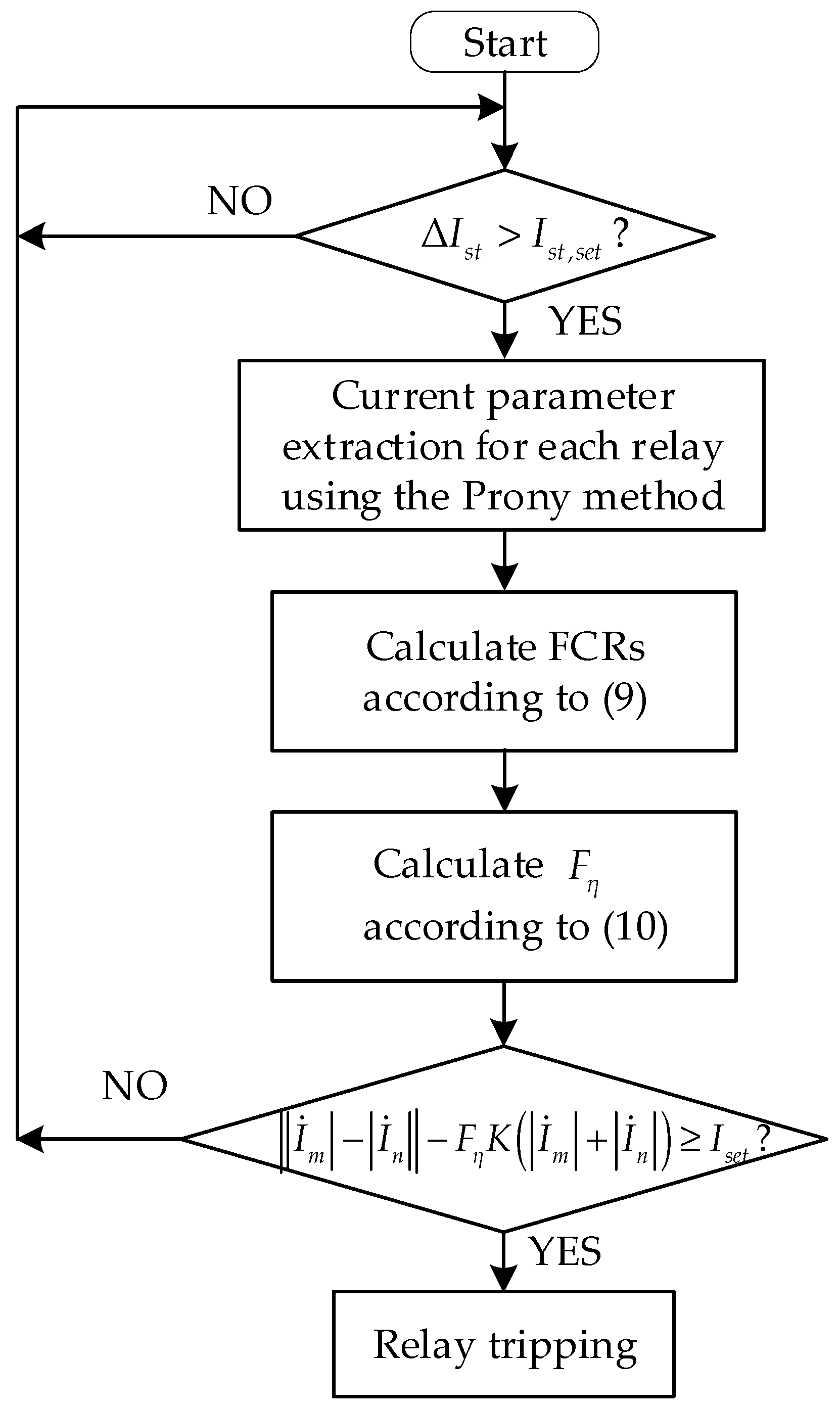
3.1. Protection Principle

The CDP principle is commonly used in modern DNs due to its high sensitivity and selectivity. Here, a novel CDP principle based on low-order harmonic components is proposed in this paper. The current variation is adopted as the start-up criterion. Once protection relays are picked up, protective relays at two terminals acquire the required transient electric quantity based on the Prony method. The frequency-characteristic ratio (FCR) is constructed to adaptively adjust the restraint coefficient. Finally, an FCR-based protection criterion is implemented to overcome issues of false or failed tripping of relays in DNs with IIDGs.
To avoid the unbalanced current during normal operations, the proposed start-up criterion based on the current variation is as follows:
Δ I s t > I s t , s e t
where I s t , s e t is the pickup threshold of the phase current.
The ratio of the sum of the amplitude of power-frequency components to the sum of the amplitudes of low-order harmonic components for transient currents within a frequency band is defined as the FCR, which is given as:
η = 49 f i 51 A i 20 f i 220 A i
where A i is the amplitude of transient currents current at a frequency f i . Considering the effect of decaying components of transient currents, the frequency band of low-order harmonic components is selected to be in the interval of 20~220 Hz, which includes second-order harmonic components, third-order harmonic components and fourth-order harmonic components. The frequency band of power-frequency components is selected to be in the interval of 49~51 Hz.
To further improve the sensitivity and reliability of protection relays, a frequency factor F η based on the FCRs in (9) is defined as follows:
F η = min ( η m , η n ) max ( η m , η n )
where m and n are two-terminal relays. The frequency factor F η can be adaptively decreased when there is a large difference in FCRs between two-terminal relays, otherwise it will remain the same when there is a small difference in FCRs.
Based on (10), the action criterion of the CDP is as follows:
I ˙ m I ˙ n F η K I ˙ m + I ˙ n I s e t
where I ˙ m and I ˙ n are the amplitude of currents at two-terminal relays m and n of the feeder, respectively; K is the restraint coefficient; and I s e t is the relay setting of the CDP. Based on (10) and (11), the larger the FCR η for both terminal relays, the smaller the F η will be. The sensitivity of relays can be improved adaptively for a fault feeder. The FCRs of both terminal relays are closed for a non-fault feeder, which ensures protection selectivity and reliability. Furthermore, the protection scheme is also applicable to the traditional DN without an IIDG, due to insignificant differences in FCRs.

3.2. Prony Method

To extract the low-order harmonic components of the fault current, the nth-order Prony method is employed to fit the required electrical quantity of relays in DNs with IIDGs. The current i at a time interval ΔT is sampled uniformly and discretely for a certain period with a total number of samples M. The discrete function is:
i ^ m = x = 1 n c x y x m , m = 0 , 1 , , M 1 c x = A x e j φ x y x m = e ( β x + j 2 π f x ) Δ T
where i ^ m is the fitted approximation of i m ; A x , φ x , f x and β x are the amplitude, initial phase, damping coefficient and frequency of the x-th complex exponential function, respectively. The solution process is as follows:
1.
According to (12), the sample function can be defined as:
r ( i , j ) = m = n e M 1 i ^ ( m j ) i ^ ( m i ) i , j = 0 , 1 , , n
where i ^ * is the conjugate of i ^ .
2.
Construct the sample matrix Q :
Q = q ( 1 , 0 ) q ( 1 , 1 ) q ( 1 , n e ) q ( 2 , 0 ) q ( 1 , 1 ) q ( 1 , n e ) q ( n e , 0 ) q ( n e , 1 ) q ( n e , n e )
where n e is the order after the expansion, which is M / 2 .
3.
Using the singular value decomposition and least square estimation to determine the effective rank and all the parameters of the characteristic equation a x x = 1 , 2 , , n , substitute a x into (15) to solve y x i = 1 , 2 , , n :
x = 0 n a x y n i = 0
4.
Obtain the linear fit values in (16) based on the parameter a x .
i ^ ( m ) = x = 1 n a x i ^ ( m x )
5.
Calculate the parameters c x i = 1 , 2 , , n using (17)
1 1 1 y 1 y 2 y n y 1 M 1 y 2 M 1 y n M 1 c 1 c 2 c n = i ^ 0 i ^ 1 i ^ M 1
6.
A x , φ x , f x and β x can be yielded using the relationship between the parameters shown in (18).
A x = c x φ x = arctan Im ( c x ) Re ( c x ) f x = arctan Im ( y x ) Re ( y x ) / 2 π Δ T β x = ln y x / Δ T
Thus, the overall flowchart of the proposed CDP scheme for DNs with IIDGs considering delay behaviors of the sequence-component extractor is illustrated in Figure 6. Algorithm 1 shows the pseudocode of the proposed CDP scheme.
Algorithm 1: Pseudocode of the proposed CDP scheme
1:    Load current data from PSCAD (Im, In)
2:  Obtain magnitude and phase information of currents by the Prony algorithm (result_A, result_B)
3:    result_A= [Ax_m, fx_m, phix_m, betax_m]
4:    result_B= [Ax_n, fx_n, phix_n, betax_n]
5:    n=length(result_A)
6:    F1_m=0
7:    F2_m=0
8:    for i=1: n−1
9:          if (result_A(i,2)>=49 & result_A(i,2) <=51)
10:              F1_m= F1_m+result_A(i,1)
11:          end
12:        if (result_A(i,2)>=20 && result_A(i,2) <=220
13:                F2_m= F2_2+result_A(i,1);
14:        end
15:    end
16:     η A =F1_m/F2_m;
17:    F1_n=0
18:    F2_n=0
19:    for i=1: n−1
20:          if (result_B(i,2)>=49 & result_B(i,2)<=51)
21:                F1_n= F1_n+result_B(i,1);
22:        end
23:        if (result_A(i,2)>=20 && result_B(i,2)<=220
24:                  F2_n= F2_n+result_B(i,1);
25:        end
26:    end
27:     η B =F1_n/F2_n
28:     F η =min( η A , η B )/max( η A , η B )
29:    if abs(abs(Im)-abs(In))-K* F η *(abs(Im)+abs(In))>=I_set
30:    disp(‘YES’)
31:    end

4. Case Study

In this section, a typical radial DN with IIDGs is built using the PSCAD/EMTDC simulation platform as shown in Figure 7, where two feeders (L1 and L2) are modeled with lengths of 9 km and 7 km. The rest of the parameters in the DN are shown in Table 1.

4.1. Verification of Fault Transient Analysis Method

4.1.1. Fault Characteristics

To verify the correctness of the effects of measurement errors generated by T/4 delay behaviors of the sequence component extractor on IIDG transient currents, Figure 7 shows a three-phase symmetrical fault occurring at f 1 of the DN, where the PCC voltage drops to 60%. The three-phase PCC voltage u a b c , actual PCC voltage U ˙ P C C d q and the PCC voltage measurement U ˙ P C C , m d q are shown in Figure 8.
From Figure 8, three-phase voltages u a b c remain symmetrical after the fault. PCC voltages in the q-axis are zero because the d-axis is oriented to the PCC voltages. The amplitude of the actual PCC voltage U ˙ P C C 1 d q falls from 1.0 pu to 0.6 pu, while the measured PCC voltage U ˙ P C C , m 1 d q will undergo a transient process with a stepwise drop due to measurement errors introduced by T/4 delay behaviors. The amplitude of U ˙ P C C , m 1 d q decreases from 1.0 pu to 0.8 pu and then drops from 0.8 pu to 0.6 pu. A 5 ms dynamic error between measured PCC voltage and the actual value after the fault will affect transient characteristics of the fault current of IIDGs, which is theoretically identical to the fault analysis.

4.1.2. Comparison with Traditional Method

The output current of IIDGs and the amplitude-frequency characteristics of an A-phase current are compared when a three-phase symmetrical fault occurs at f 1 and the system voltage drops to 20%. Comparison results between the method proposed in this paper and the traditional algorithm [39] are shown in Figure 9.
In Figure 9a, the transient process of the IIDG fault current under the system voltage drop of 20% is divided into two stages. Due to the voltage feedforward error and LVRT control strategy, the d-axis and q-axis current increases within the first 5 ms of stage I. As for stage II, feedforward errors between measured voltages and actual voltages gradually become 0 and the reference current in the q-axis increases again. Compared with the traditional method, the q-axis current significantly overshoots with a maximum of 2.39 pu and then reaches the command value. From Figure 9b, it is found that all the low-order harmonic components of the IIDG fault current will increase. The second-order harmonic components of the transient current are the dominant components, which is consistent with the previous analysis.
From Figure 9a,b, it can be seen that the traditional equivalent model does not correctly reflect the transient characteristics of the IIDG fault currents within 0–20 ms after the fault, whereas the model used in this paper has a better match result. Furthermore, this section quantitatively compares the accuracy of the two models under different levels of voltage reductions, as shown in Table 2 and Table 3. In the case of voltages which dropped by 20%, the calculation accuracy of the traditional methods is between 1% and 3% within 20 ms after a fault, while the accuracy of the model in this study is less than 0.01%. When the system voltage drops by 80%, the computational error of the traditional method exceeds 30% within 20 ms after a fault, which can reach 71.61% at maximum. The calculation accuracy of the proposed model is still below 0.1%, the computational accuracy is improved by more than 30%, and the narrower the time window, the more obviously the computational accuracy is improved.
Therefore, the proposed method in this study has high accuracy in fault calculations which is identical to the theoretical analyses and demonstrates the accuracy of the fault transient analysis of IIDG considering T/4 delay behaviors, as summarized in this paper.

4.2. Different Locations and Fault Resistances

To verify the performance of the proposed protection scheme under various locations and fault resistances, 27 groups of two-phase (A-phase and B-phase) grounding faults are simulated in the DN model shown in Figure 7, where K is set to 0.2 and I s e t is set to 0.1 kA. The fault points are f 1 , f 2 and f 3 , respectively. The fault resistances are set to 10 Ω, 100 Ω and 500 Ω, respectively. The operation results of relays are shown in Table 4. I a c t is the two-terminal differential currents of faulty sections for the action criterion in (4), which is equal to I ˙ m I ˙ n F η K I ˙ m + I ˙ n .
In the results shown in Table 4, the proposed protection scheme can correctly identify faults at different locations and fault resistances. When a fault f 2 occurs downstream of the protected section, the short-circuit current flowing through relays on both sides of AB is supplied by the system. The calculated FCRs on both sides are similar, that is, F η close to 1. In the case of the fault occurring at a point, f 3 , that is located at the outlet of a neighboring feeder on the same bus, a backward power flow may occur. The short-circuit currents at the relays on both sides of AB are contributed by the IIDG. The FCRs on both sides are small but approximately equal, that is, F η is still close to 1. In summary, the relay can reliably trip to eliminate faults with good sensitivity and generality.
Furthermore, to show the correctness of the reconstructed electrical quantity of relays, the performance of the Prony algorithm implemented in the proposed protection method is assessed in Table 4 ( f 1 , 50%, 10 Ω). A comparison between fitted curves based on the Prony algorithm and simulated curves from PSCAD is given in Figure 10, where I ˙ m and I ˙ n are terminal currents of the section AB of Figure 7. From Figure 10, it is evident that the terminal currents I ˙ m and I ˙ n have been successfully fitted by the Prony algorithm, with a high fitting accuracy. The above retrieved results are correctly applied to the protection criterion, which can indirectly validate the effectiveness of the proposed methodology.

4.3. Different Fault Types

To verify the correctness of the proposed protection scheme in case of different fault types, two-phase short-circuit faults (A-phase and B-phase), two-phase to ground faults (A-phase and B-phase) and three-phase short-circuit faults are simulated at the midpoint of the AB section shown in Figure 7, respectively. The fault resistances are set to 1 Ω, 5 Ω, 50 Ω and 100 Ω, respectively. The simulation results are shown in Table 5. It can be seen from Table 5 that the proposed protection scheme can identify different fault types and each relay trips correctly. In the event of a serious fault, IIDG may provide a large number of harmonic currents. η calculated by relays on the IIDG side and F η are close to 0, which can maximize the protection sensitivity.

4.4. IIDG Output Power and Location

As the IIDG output power increases, the voltage support capabilities provided by the IIDG to the grid will become stronger after a fault, according to the LVRT control strategy. It ensures that the DN can continue to operate stably and weakens the fault current characteristics of the grid, which may result in traditional fixed restraint coefficients refusing to trip. To assess the impact of IIDGs on the proposed method, different IIDG output powers and locations are tested based on the model shown in Figure 7. The operation results of relays are obtained, as shown in Table 6, where the AB two-phase ground fault occurs at the fault point f 1 , IIDG1 output powers are set to 1 MW, 2 MW, 3 MW and 4.5 MW, respectively, and the locations are 0.5 km, 1.5 km and 2.5 km from bus A, respectively; the fault resistance is set to 10 Ω. From the results shown in Table 6, it can be found that the proposed protection schemes can be operated accurately after a fault under different IIDG output power and locations. The proposed CDP scheme is immune to the output powers and locations of IIDGs.

4.5. DNs without IIDGs

To evaluate the performance of the proposed scheme on the traditional DN without IIDGs, IIDG is not considered in the model shown in Figure 7. The fault locations, fault resistances and other fault conditions are the same as those in Section 4.2. Table 7 shows the operation results for the relays in the proposed protection scheme.
As can be seen in Table 7, the proposed protection schemes can accurately judge the fault and disconnect the faulty line for the traditional DN without IIDGs. Furthermore, a comparison of Table 6 and Table 7 also indicates that IIDGs will contribute low-order harmonic components in the post-fault transient process for DNs, which confirms the validity of the previous conclusion. The method is efficient for a DN without IIDGs or with IIDGs, with good adaptability.

5. Discussion

Steady-state-based fault analyses of IIDGs have been studied by different scholars in the past [4,27,38,39,40]. To analyze and calculate fault currents of IIDGs more accurately, delay behaviors of sequence-component extractors have to be considered, which is an important prerequisite for the study of fault features and relay protection. The results in Table 2 and Table 3 show that the maximum error of the proposed fault analysis method is below 0.06%, with higher accuracy in fault calculations than the above methods.
The protection system in [11] is capable of clearing ground faults only, while the performance under different fault types needs a deeper examination. Table 4 and Table 5 demonstrate the good performance of the proposed method during different fault types. Referring to the existing literature [14,38], the adaptive scheme needs to obtain the IIDG information; however, electrical quantities or parameters of IIDGs are not readily available through relays and instrument transformers in DNs due to construction costs [23]. The active methodology [42] that relies on injecting the frequency signal may be costly and has a potential risk to the utility grid, which limits the application in real-life engineering. Fortunately, there is no need to obtain or exchange electrical information of each IIDG, so the proposed protection scheme is an economically feasible solution for DNs incorporating multiple IIDGs, without the requirements for the supplementary signal equipment and physical injections.
In addition, the flexible access of IIDGs, including the T-connection and bus-connection in the protection zone, will decrease the reliability and sensitivity of the conventional CDP [27] and could trigger process failure, while the proposed method can adapt to the flexible access of IIDGs with different output powers and locations, as shown in Table 6 and Table 7, with good practicality and performance. In particular, the technique applied in this paper has low arithmetic complexity compared to those heuristic algorithms [22,26]. The noteworthy transient feature shown in Figure 8 and Figure 9 is used to identify faults in DNs with IIDGs. Considering today’s relay protection configurations, it is not difficult to achieve the requirements of the extraction of transient features and may be successfully implemented in the actual DNs.
The variety of DGs will increase with more diverse power electronics interfaces and control strategies in future DNs. Although the protection scheme here is described for a DN with PQ-IIDGs, the fault analysis method and protection philosophy in this paper can provide a theoretical basis and guidance for further research. Moreover, the proposed principle can be carried out on the existing communication-based protection system, which has a certain requirement for the communication of DNs. If the communication links between the relays at both terminals fail to function, it may lead to failure identification for faults in DNs due to missing or time-delayed information. Such a communication failure or latency is beyond the scope of this paper but will be addressed in future work.

6. Conclusions

A novel CDP framework using delay features that are contributed by the sequence component extractor has been proposed in this paper for protecting IIDG-dominated DNs. The T/4 delay behaviors associated with the grid-connected PQ-IIDGs are added to the fault analysis of DNs and the required mathematical model in the frequency domain is presented. It is found that, the two-stage delay behavior in the fault transient process for IIDGs will generate low-order harmonic components where the second-order harmonic components increase significantly. For the current differential relays, FCRs have been obtained using the Prony technique to construct the protection criteria.
The study shows that the proposed fault analysis method has high accuracy in fault calculations for transient electrical quantities for IIDGs. The feasibility of the FCRs-based current differential principle is substantiated by the simulation results under various fault types, fault locations and fault resistances, which is well adaptable to different IIDG locations and capacities. It is clear that the proposed protection does not require additional equipment to obtain electrical information from the PCCs of IIDGs, with favorable economic benefits. Consequently, this method is simple and could be a good solution for DNs with or without IIDGs.
Future work that involves various power electronics interfaces and control strategies of DGs connected to DNs, as well as communication failures, should be performed to show the adaptability and validity of the proposed fault analysis method and CDP philosophy.

Author Contributions

Conceptualization, G.W. and M.H.; methodology, J.L. and M.H.; software, C.L.; validation, M.H. and J.L.; formal analysis, G.W.; investigation, H.B.; resources, H.B. and R.Y.; data curation, H.W.; writing—original draft preparation, G.W. and M.H.; writing—review and editing, J.L.; supervision, R.Y.; funding acquisition, J.L. and H.B. All authors have read and agreed to the published version of the manuscript.

Funding

This research was funded by the science and technology project of China’s southern power grid, grant number GZHKJXM20200081, and the science and technology program of Guangzhou, China, grant number 2023A04J1589.

Data Availability Statement

Data are contained within the article.

Conflicts of Interest

The authors declare no conflict of interest.

References

  1. Medhat, W.; Azzouz, M.A. Triple Current Control of Four-Wire Inverter-Interfaced DGs for Correct Fault Type Identification. IEEE Trans. Smart Grid 2022, 13, 3607–3618. [Google Scholar] [CrossRef]
  2. Gunawardane, K.; Bandara, N.; Subasinghage, K.; Kularatna, N. Extending the Input Voltage Range of Solar PV Inverters with Supercapacitor Energy Circulation. Electronics 2021, 10, 88. [Google Scholar] [CrossRef]
  3. Alatrash, H.; Mensah, A.; Mark, E.; Haddad, G.; Enslin, J. Generator Emulation Controls for Photovoltaic Inverters. IEEE Trans. Smart Grid 2012, 3, 996–1011. [Google Scholar] [CrossRef]
  4. Wang, Q.; Zhou, N.; Ye, L. Fault Analysis for Distribution Networks with Current-Controlled Three-Phase Inverter-Interfaced Distributed Generators. IEEE Trans. Power Deliv. 2015, 30, 1532–1542. [Google Scholar] [CrossRef]
  5. Wang, C.; Pang, K.; Shahidehpour, M.; Wen, F. MILP-Based Fault Diagnosis Model in Active Power Distribution Networks. IEEE Trans. Smart Grid 2021, 12, 3847–3857. [Google Scholar] [CrossRef]
  6. Mahamedi, B.; Eskandari, M.; Fletcher, J.E.; Zhu, J. Sequence-Based Control Strategy with Current Limiting for the Fault Ride-Through of Inverter-Interfaced Distributed Generators. IEEE Trans. Sustain. Energy 2020, 11, 165–174. [Google Scholar] [CrossRef]
  7. Haj-ahmed, M.A.; Illindala, M.S. The Influence of Inverter-Based DGs and Their Controllers on Distribution Network Protection. IEEE Trans. Ind. Appl. 2014, 50, 2928–2937. [Google Scholar] [CrossRef]
  8. Chen, L.-H. Overcurrent Protection for Distribution Feeders with Renewable Generation. Int. J. Electr. Power Energy Syst. 2017, 84, 202–213. [Google Scholar] [CrossRef]
  9. Andruszkiewicz, J.; Lorenc, J.; Staszak, B.; Weychan, A.; Zięba, B. Overcurrent Protection against Multi-Phase Faults in MV Networks Based on Negative and Zero Sequence Criteria. Int. J. Electr. Power Energy Syst. 2022, 134, 107449. [Google Scholar] [CrossRef]
  10. Rahmati, A.; Adhami, R. An Overcurrent Protection Relay Based on Local Measurements. In Proceedings of the 2013 IEEE Industry Applications Society Annual Meeting, Lake Buena Vista, FL, USA, 6–11 October 2013. [Google Scholar]
  11. Li, J.; Feng, J.; Bai, H.; Wang, H.; Li, W.; Huang, M.; Wang, G. An Adaptive Protection Scheme for Multiple Single-Phase Grounding Faults in Radial Distribution Networks with Inverter-Interfaced Distributed Generators. Int. J. Electr. Power Energy Syst. 2023, 152, 109221. [Google Scholar] [CrossRef]
  12. Qiang, J. Study on Adaptive Current Instantaneous Trip Protection Scheme for Distribution Network with Inverter Interfaced DG. Autom. Electr. Power Syst. 2009, 31, 71–76. [Google Scholar]
  13. Yousaf, M.; Muttaqi, K.M.; Sutanto, D. A Control Strategy to Mitigate the Sensitivity Deterioration of Overcurrent Protection in Distribution Networks with the Higher Concentration of the Synchronous and Inverter-Based DG Units. IEEE Trans. Ind. Applicat. 2021, 57, 2298–2306. [Google Scholar] [CrossRef]
  14. Zeng, D.; Wang, G.; Guo, J.; Sun, X. Adaptive Current Protection Scheme for Distribution Network with Inverter-Interfaced Distributed Generators. Autom. Electr. Power Syst. 2017, 41, 86–92. [Google Scholar]
  15. Salem, M.M.; Elkalashy, N.I.; Atia, Y.; Kawady, T.A. Modified Inverter Control of Distributed Generation for Enhanced Relaying Coordination in Distribution Networks. IEEE Trans. Power Deliv. 2017, 32, 78–87. [Google Scholar] [CrossRef]
  16. Zeineldin, H.H.; Sharaf, H.M.; Ibrahim, D.K.; El-Zahab, E.E.-D.A. Optimal Protection Coordination for Meshed Distribution Systems with DG Using Dual Setting Directional Over-Current Relays. IEEE Trans. Smart Grid 2015, 6, 115–123. [Google Scholar] [CrossRef]
  17. Saldarriaga-Zuluaga, S.D.; López-Lezama, J.M.; Muñoz-Galeano, N. An Approach for Optimal Coordination of Over-Current Relays in Microgrids with Distributed Generation. Electronics 2020, 9, 1740. [Google Scholar] [CrossRef]
  18. Ukil, A.; Deck, B.; Shah, V.H. Current-Only Directional Overcurrent Protection for Distribution Automation: Challenges and Solutions. IEEE Trans. Smart Grid 2012, 3, 1687–1694. [Google Scholar] [CrossRef]
  19. Jia, K.; Yang, Z.; Fang, Y.; Bi, T.; Sumner, M. Influence of Inverter-Interfaced Renewable Energy Generators on Directional Relay and an Improved Scheme. IEEE Trans. Power Electron. 2019, 34, 11843–11855. [Google Scholar] [CrossRef]
  20. Zidan, A.; El-Saadany, E.F. A Cooperative Multiagent Framework for Self-Healing Mechanisms in Distribution Systems. IEEE Trans. Smart Grid 2012, 3, 1525–1539. [Google Scholar] [CrossRef]
  21. Yinger, R.J. Self-Healing Circuits at Southern California Edison. In PES T&D 2012; IEEE: New York, NY, USA, 2012; pp. 1–3. [Google Scholar]
  22. Casagrande, E.; Woon, W.L.; Zeineldin, H.H.; Svetinovic, D. A Differential Sequence Component Protection Scheme for Microgrids with Inverter-Based Distributed Generators. IEEE Trans. Smart Grid 2014, 5, 29–37. [Google Scholar] [CrossRef]
  23. Gao, H.; Li, J.; Xu, B. Principle and Implementation of Current Differential Protection in Distribution Networks with High Penetration of DGs. IEEE Trans. Power Deliv. 2017, 32, 565–574. [Google Scholar] [CrossRef]
  24. Nikolaidis, V.C.; Michaloudis, G.; Tsimtsios, A.M.; Tzelepis, D.; Booth, C.D. A Coordinated Multi-Element Current Differential Protection Scheme for Active Distribution Systems. IEEE Trans. Power Deliv. 2022, 37, 4261–4271. [Google Scholar] [CrossRef]
  25. Zhou, C.; Zou, G.; Zang, L.; Du, X. Current Differential Protection for Active Distribution Networks Based on Improved Fault Data Self-Synchronization Method. IEEE Trans. Smart Grid 2022, 13, 166–178. [Google Scholar] [CrossRef]
  26. Zhou, C.; Zou, G.; Zhang, S.; Zheng, M.; Tian, J.; Du, T. Mathematical Morphology-Based Fault Data Self-Synchronization Method for Differential Protection in Distribution Networks. IEEE Trans. Smart Grid 2023, 14, 2607–2620. [Google Scholar] [CrossRef]
  27. Han, B.; Li, H.; Wang, G.; Zeng, D.; Liang, Y. A Virtual Multi-Terminal Current Differential Protection Scheme for Distribution Networks with Inverter-Interfaced Distributed Generators. IEEE Trans. Smart Grid 2018, 9, 5418–5431. [Google Scholar] [CrossRef]
  28. Chen, G.; Liu, Y.; Yang, Q. Impedance Differential Protection for Active Distribution Network. IEEE Trans. Power Deliv. 2020, 35, 25–36. [Google Scholar] [CrossRef]
  29. Hossain, M.; Leevongwat, I.; Rastgoufard, P. Revisions on Alpha Plane for Enhanced Sensitivity of Line Differential Protection. IEEE Trans. Power Deliv. 2018, 33, 3260–3262. [Google Scholar] [CrossRef]
  30. Nsengiyaremye, J.; Pal, B.C.; Begovic, M.M. Low-Cost Communication-Assisted Line Protection for Multi-Inverter Based Microgrids. IEEE Trans. Power Deliv. 2021, 36, 3371–3382. [Google Scholar] [CrossRef]
  31. Nsengiyaremye, J.; Pal, B.C.; Begovic, M.M. Microgrid Protection Using Low-Cost Communication Systems. IEEE Trans. Power Deliv. 2020, 35, 2011–2020. [Google Scholar] [CrossRef]
  32. Li, X.; Lu, Y. Improved Amplitude Differential Protection Scheme Based on the Frequency Spectrum Index for Distribution Networks with DFIG-Based Wind DGs. IEEE Access 2020, 8, 64225–64237. [Google Scholar] [CrossRef]
  33. Lin, X.; Ma, X.; Wang, Z.; Sui, Q.; Li, Z.; Ye, Y.; Wu, Y.; Cao, S.; Wang, G. A Novel Current Amplitude Differential Protection for Active Distribution Network Considering the Source-Effect of IM-Type Unmeasurable Load Branches. Int. J. Electr. Power Energy Syst. 2021, 129, 106780. [Google Scholar] [CrossRef]
  34. Chowdhury, A.; Paladhi, S.; Pradhan, A.K. Adaptive Unit Protection for Lines Connecting Large Solar Plants Using Incremental Current Ratio. IEEE Syst. J. 2022, 16, 3272–3283. [Google Scholar] [CrossRef]
  35. Zheng, X.; Chao, C.; Weng, Y.; Ye, H.; Liu, Z.; Gao, P.; Tai, N. High-Frequency Fault Analysis-Based Pilot Protection Scheme for a Distribution Network with High Photovoltaic Penetration. IEEE Trans. Smart Grid 2023, 14, 302–314. [Google Scholar] [CrossRef]
  36. Pathirana, A.; Rajapakse, A.; Perera, N. Development of a Hybrid Protection Scheme for Active Distribution Systems Using Polarities of Current Transients. Electr. Power Syst. Res. 2017, 152, 377–389. [Google Scholar] [CrossRef]
  37. Dong, J.; Pan, J.; Mao, X. Low Voltage Ride-through Strategy of VSG Based on Adaptive Positive and Negative Sequence Composite Control. Power Syst. Technol. 2023, 47, 815–822. [Google Scholar]
  38. Li, H.; Deng, C.; Zhang, Z.; Liang, Y.; Wang, G. An Adaptive Fault-Component-Based Current Differential Protection Scheme for Distribution Networks with Inverter-Based Distributed Generators. Int. J. Electr. Power Energy Syst. 2021, 128, 106719. [Google Scholar] [CrossRef]
  39. Li, J.; Bi, H.; Li, C.; Li, J.; Zeng, D.; Wang, G. Analysis and Calculation Method for Multiple Faults in Low-Resistance Grounded Systems with Inverter-Interfaced Distributed Generators Based on a PQ Control Strategy. Int. J. Electr. Power Energy Syst. 2022, 138, 107980. [Google Scholar] [CrossRef]
  40. Pan, G.; Zeng, D.; Wang, G.; Zhu, G.; Li, H. Fault Analysis on Distribution Network with Inverter Interfaced Distributed Generations Based on PQ Control Strategy. Proc. CSEE 2014, 34, 555–561. [Google Scholar]
  41. Yao, R.; Sun, K.; Qiu, F. Vectorized Efficient Computation of Padé Approximation for Semi-Analytical Simulation of Large-Scale Power Systems. IEEE Trans. Power Syst. 2019, 34, 3957–3959. [Google Scholar] [CrossRef]
  42. Soleimanisardoo, A.; Kazemi Karegar, H.; Zeineldin, H.H. Differential Frequency Protection Scheme Based on Off-Nominal Frequency Injections for Inverter-Based Islanded Microgrids. IEEE Trans. Smart Grid 2019, 10, 2107–2114. [Google Scholar] [CrossRef]
Figure 1. Closed-loop control system of a grid-connected IIDG.
Electronics 12 04727 g001
Figure 2. Transfer function diagram of fault currents of IIDGs considering the T/4 delay behaviors.
Electronics 12 04727 g002
Figure 3. Unit step responses for positive-and negative-sequence components of PCC voltages.
Electronics 12 04727 g003
Figure 4. Transfer function diagram of reference positive- and negative-sequence current values to those actual currents.
Electronics 12 04727 g004
Figure 5. The amplitude-frequency and phase-frequency characteristic curves of the transfer function of the output current of the IIDG.
Electronics 12 04727 g005
Figure 6. Flowchart of the proposed CDP scheme.
Electronics 12 04727 g006
Figure 7. Typical radial DNs with IIDGs.
Electronics 12 04727 g007
Figure 8. Fault waveforms for PCC voltages.
Electronics 12 04727 g008
Figure 9. Comparative results of fault currents.
Electronics 12 04727 g009
Figure 10. Comparison between fitted curves based on the Prony algorithm and simulated curves from PSCAD.
Electronics 12 04727 g010
Table 1. Parameters of DNs.
ParameterValue
System equivalent impedance0.0001 + j0.628 (Ω)
Main transformer capacity50 (MVA)
Main transformer ratio110 kV/10.5 kV
Load capacity10 (MVA)
Load power factor0.9
Line impedance0.06 + j0.089 (Ω/km)
Length of line AB3 (km)
Length of line BC4 (km)
Length of line AD5 (km)
IIDG1, IIDG2 and IIDG3 capacity3, 1.5 and 4 (MVA)
Fault time0.2 (s)
Table 2. Comparison of the two models when the system voltage drops to 80%.
MethodCurrent5 ms10 ms20 ms
Proposed
Method
d-axis<0.01%<0.01%<0.01%
q-axis<0.01%<0.01%<0.01%
Method in [39] d-axis1.74%1.64%1.36%
q-axis2.03%1.93%1.56%
Table 3. Comparison of the two models when the system voltage drops to 20%.
MethodCurrent5 ms10 ms20 ms
Proposed
Method
d-axis0.02%0.03%0.05%
q-axis0.03%0.06%0.05%
Method in [39]d-axis71.61%49.38%33.22%
q-axis3.99%15.31%7.86%
Table 4. Operation results of the relays for the proposed protection scheme under different fault locations and resistances.
Fault PointFault LocationFault
Resistance (Ω)
η A η B F η I a c t (kA)Relay AB
Tripped or Not
Relay
f 1 10%1010.84570.839810.5620YESAB
1000.99900.81710.818010.6497YESAB
5000.99910.81850.819210.6496YESAB
50%100.99790.90810.93857.9419YESAB
1000.99810.92160.92337.9289YESAB
5000.99770.93160.93387.9563YESAB
90%100.99800.86250.86436.4316YESAB
1000.99790.87230.87416.1900YESAB
5000.99730.87580.81816.5142YESAB
f 2 10%100.99770.99750.99997.5339NOBC
1000.99780.99720.99937.3486NOBC
5000.99660.99630.99997.5341NOBC
50%100.98630.98620.99995.9441NOBC
1000.98660.98630.99975.0407NOBC
5000.98630.98640.99995.9212NOBC
90%100.98690.98660.99994.7786NOBC
1000.98580.98570.99995.4212NOBC
5000.98700.98690.99995.2130NOBC
f 3 10%100.88530.88670.99849.9337NOAD
1000.88790.88640.998310.2895NOAD
5000.88710.88570.99849.9200NOAD
50%100.87420.87530.99876.6909NOAD
1000.80650.80150.99386.7521NOAD
5000.79530.79890.99556.6799NOAD
90%100.91110.91390.99694.9530NOAD
1000.88480.88630.99844.9544NOAD
5000.80810.79620.98534.9296NOAD
Table 5. Operation results of the relays for the proposed protection scheme under different fault types.
Fault TypeFault Resistance (Ω) η A η B F η I a c t (kA)Trip or Not
three-phase short-circuit fault0.99610.00010.00018.6650YES
two-phase short-circuit fault0.99840.96470.96628.3815YES
two-phase to ground fault10.99780.91310.91517.8778YES
50.99810.88460.88638.0605YES
500.99790.88140.88328.0672YES
1000.99790.91020.91218.0038YES
Table 6. Operation results of the relays for the proposed protection scheme under different IIDG output powers and locations.
IIDG Output Power (MVA)IIDG
Location (km)
η A η B F η I a c t (kA)Trip or Not
10.50.99770.94310.94538.3592YES
1.50.99760.94910.95158.3423YES
2.50.99760.93780.94018.3371YES
20.50.99760.93010.93238.3432YES
1.50.99770.93770.93998.3379YES
2.50.99770.92690.92908.4387YES
30.50.99750.92080.923118.2625YES
1.50.99790.91410.91608.3865YES
2.50.99800.91630.91818.3367YES
4.50.50.99760.90260.90488.2436YES
1.50.99740.90380.90618.2242YES
2.50.99790.90110.90308.3819YES
Table 7. Operation results for the relays in the proposed protection scheme for the traditional DN without IIDGs.
Fault PointFault LocationFault
Resistance (Ω)
η A η B F η I a c t (kA)Relay AB
Tripped or Not
Relay
f 1 10%100.98930.99980.989510.3600YESAB
1000.99980.99990.999910.7699YESAB
5000.98990.99710.992810.3574YESAB
50%101.00001.00001.00008.1853YESAB
1000.99930.99900.99978.4347YESAB
5000.99950.99960.99998.2247YESAB
90%100.99960.99750.99796.4943YESAB
1000.99910.99940.99976.4898YESAB
5000.99860.99820.99966.5035YESAB
f 2 10%101.00001.00001.00006.8398NOBC
1000.99780.99781.00006.8314NOBC
5000.99630.99620.99996.8742NOBC
50%101.00001.00001.00004.6295NOBC
1000.98880.99010.99874.6328NOBC
5000.99840.99850.99995.4846NOBC
90%100.99520.99890.99644.8398NOBC
1000.99680.99860.99824.6977NOBC
5000.99540.99580.99965.5084NOBC
f 3 10%101.00001.00001.000010.1800NOAD
1000.99980.99981.000010.1804NOAD
5000.99970.99980.999910.1761NOAD
50%101.00001.00001.00006.8431NOAD
1000.99960.99920.99966.8430NOAD
5001.00000.99980.99986.8427NOAD
90%101.00001.00001.00005.0166NOAD
1000.99820.99870.99955.0142NOAD
5000.99990.99991.00005.0158NOAD
Disclaimer/Publisher’s Note: The statements, opinions and data contained in all publications are solely those of the individual author(s) and contributor(s) and not of MDPI and/or the editor(s). MDPI and/or the editor(s) disclaim responsibility for any injury to people or property resulting from any ideas, methods, instructions or products referred to in the content.

