Article

FPGA-Based Extended Control Set Model Predictive Current Control with a Simplified Search Strategy for Permanent Magnet Synchronous Motor

School of Electrical Engineering, Southeast University, Nanjing 210096, China
*
Author to whom correspondence should be addressed.
Electronics 2023, 12(23), 4726; https://doi.org/10.3390/electronics12234726
Submission received: 15 October 2023 / Revised: 16 November 2023 / Accepted: 20 November 2023 / Published: 21 November 2023
(This article belongs to the Section Power Electronics)

Abstract

:
The conventional finite control set model predictive current control (FCS-MPCC) suffers from suboptimal steady-state performance, primarily due to the limited selection of only eight basic voltage vectors in each control cycle. To overcome this limitation, the proposed extended control set MPCC (ECS-MPCC) utilizes an control set consisting of 818 selectable vectors, enabling a more refined voltage output and achieving a deadbeat response for current control by minimizing the cost function. To mitigate the computational burden resulting from the substantial increase in voltage vectors, a simplified search strategy is devised, which can be extended to other multi-objective cost functions. Remarkably, based on the inherent parallelism of the algorithm, the ECS-MPCC is implemented on an FPGA, further reducing the overall control time of the current loop to an impressive 0.61 μs. Through simulation and experimental tests on a laboratory PMSM driver, the effectiveness of the proposed ECS-MPCC strategy is validated. The experimental results demonstrate a significant reduction of 79% in the total harmonic distortion of phase currents compared to the conventional FCS-MPCC approach. This improvement underscores the superiority of the ECS-MPCC in enhancing the performance of PMSM drives, thereby illustrating its potential for practical implementation in real-world applications.

1. Introduction

Permanent magnet synchronous motor (PMSM) has been widely employed in various industrial applications due to the advantages of high torque (power) density, high efficiency and removal of brush and slip rings [1,2,3]. Model predictive control (MPC) is emerging as a promising technique for PMSM drives over the past decade [4,5,6,7], which has proven its intuitive concept and exceptional dynamic performance in other applications [8,9,10,11,12].
Based on the different voltage vector output methods, MPC strategies can be categorized into finite control set MPC (FCS-MPC) [9,10] and continuous control set MPC (CCS-MPC) [11,12]. Apart from its superior dynamic performance, FCS-MPC offers the merit of multi-objective integrated optimization [13], achieved through the high flexibility of cost function design and the traversal approach for vector determination strategy. However, the conventional FCS-MPC with limited selectable voltage vectors may result in a significant deviation between the actual output vector and the ideal vector, leading to fluctuations in phase currents and electromagnetic torque [14]. CCS-MPC, on the other hand, employs the modulation principle and pre-calculated input–output laws to generate continuously varying voltage vectors, enabling better steady-state performance compared to FCS-MPC, but its dependence on offline computations limits the applications [15]. Deadbeat control (DBC) is another widely studied predictive control [16,17,18,19], which achieves superior steady-state performance than conventional FCS-MPC and can be easily implemented on a digital controller for real-time computation. However, the potential cost function in DBC is fixed, limiting its control to a single objective and lacking the ability of multi-objective integrated optimization. Hence, it is crucial to explore an improved MPC method that can simultaneously possess high steady-state performance, convenience for real-time computation, and the ability of multi-objective integrated optimization, which is exactly the objective of this paper.
Since the limited selectable voltage vectors in FCS-MPC result in the inferior steady-state, adding more virtual vectors to the control set to construct an extended control set (ECS) seems a quite direct solution. Vazquez et al. [20] illustrated this approach through simulations, but the actual computational burden of the digital controller was not considered, and experimental verification was not performed. To reduce the computational burden of an ECS-MPC, Wang et al. [21] proposed a method to narrow the traversal range using the location information of the DBC reference vector, but it is difficult for multi-objective integrated optimization since the DBC potential cost function contains only one single objective. Furthermore, the subdivision degree of the fundamental voltage vectors in [21] remains limited, and cannot meet higher steady-state performance requirements.
In terms of algorithm execution, both FCS-MPC and ECS-MPC derive their main computational effort from predicting the effects and judging the superiority of different voltage vectors. It is evident that performing these operations for each vector in the control set can be logically parallel, which contradicts the sequential execution of common digital signal processors. Hence, the field-programmable gate array (FPGA) is more qualified in such a scenario due to its inherent parallelism. While the utilization of FPGAs in motor drives has been explored to some extent [22,23,24,25,26], FPGAs are generally used as a replacement for digital signal processors to implement non-highly computational algorithms. Therefore, research on parallel acceleration for highly computational algorithms through effective FPGA implementation requires further development.
In the ECS-MPC method, there is no restriction on the selection of control objectives. To illustrate the improvement of this method in steady-state performance, this paper focuses on current control and compares the steady-state and dynamic performances of ECS model predictive current control (ECS-MPCC), deadbeat predictive current control with discrete space vector modulation (DB-PCC with DSVM) (derived from [21]), and conventional finite control set model predictive current control (FCS-MPCC). Therefore, the theoretical analysis, simulation, and experiment in the following sections all focus on the current control.
In this paper, an FPGA-based ECS-MPCC method with a simplified search strategy is proposed. Firstly, the conventional FCS with only eight basic voltage vectors is extended to an ECS with 818 voltage vectors, thereby significantly enhancing the steady-state performance. Secondly, a simplified search strategy suitable for multi-objective optimization is proposed, leading to a substantial reduction in the traversal computation. Lastly, the ECS-MPCC method is implemented using an FPGA controller for current control. The total control time of the current loop is reduced to only 0.61 μs by highly efficient FPGA development. The proposed method follows the vector selection approach based on the cost function and traversal search of the conventional FCS-MPC so that the potential of multi-objective optimization is preserved. Simulations and experiments demonstrate the effectiveness of the proposed method.

2. Discrete Model and Conventional FCS-MPC

2.1. Discrete Mathematical Model

In this paper, a system consisting of a two-level, three-phase voltage source inverter (VSI) and a PMSM is studied. The inverter can output eight basic voltage vectors as described:
V n = 2 3 U dc S 1 + a S 2 + a 2 S 3
where n = 0, 1, …, 7 is the serial number of 8 basic voltage vectors. Udc is the DC bus voltage. S1, S2, and S3 correspond to the switching states of the three-phase inverter. a = e(2π/3)j.
A first-order forward Euler approximation model of a PMSM is usually used to predict the future state of the PMSM. In the synchronous reference frame (dq-frame), the voltage equation of a standard discrete model of a PMSM for the MPCC strategy yields [27]
i d ( k + 1 ) i q ( k + 1 ) = A i d ( k ) i q ( k ) + B u d ( k ) u q ( k ) + C
where A = 1 T s R s L d T s L q ω e ( k ) L d T s L d ω e ( k ) L q 1 T s R s L q , B = T s L d 0 0 T s L q , C = 0 T s ψ f ω e ( k ) L q .
Ts is the sampling period, Rs is the stator resistance, ωe is the rotor electrical angular velocity, id and iq are the stator d-axis and q-axis currents, respectively, and ud and uq are the stator d-axis and q-axis voltages, respectively.
Since there is a computational delay of one control cycle in the digital control system, it is necessary to correct Equation (2) when implementing the MPCC algorithm. The current prediction equations with a computational delay of one control cycle are shown in Equations (3) and (4).
i d , p r e ( k + 1 ) i q , p r e ( k + 1 ) = A i d ( k ) i q ( k ) + B u d ( k ) u q ( k ) + C
i d ( k + 2 ) i q ( k + 2 ) = A i d , p r e ( k + 1 ) i q , p r e ( k + 1 ) + B u d ( k + 1 ) u q ( k + 1 ) + C
where [ud(k) uq(k)]T is the actual output voltage vector in the k control step, and [id,pre(k + 1) iq,pre(k + 1)]T are the predictive currents that are calculated according to [ud(k) uq(k)]T and [id(k) iq(k)]T. [ud(k + 1) uq(k + 1)]T is one of the selectable voltage vectors in the k + 1 control step, and [id(k + 2), iq(k + 2)] T are the predictive currents in the k + 2 step.

2.2. Conventional FCS-MPC

The conventional FCS-MPC method mainly consists of three steps: traversal prediction, cost function calculation, and optimal vector selection. Take FCS-MPCC as an example. First, the FCS-MPCC method predicts the stator d-axis and q-axis currents (id,n, iq,n) after the action of different selectable voltage vectors based on Equations (3) and (4). Second, the control deviation caused by each selectable voltage vector is calculated by substituting the predicted current into the pre-designed cost function. A cost function with only current following as the control objective is usually designed in the form shown in Equation (5). Finally, the voltage vector that minimizes the cost function value is selected as the output of the inverter in the next control cycle.
J n = i d * i d , n 2 + i q * i q , n 2 + λ n i d , n , i q , n
where λ n i d , n , i q , n = 0 ,   i d , n 2 + i q , n 2 i max + ,   i d , n 2 + i q , n 2 > i max , which is used to constrain the amplitude of the stator current. n = 0, 1, …, 7.
The voltage output ranges of a conventional FCS-MPC and a DBC using space vector pulse width modulation (SVPWM) are compared in Figure 1. It can be found that the output voltage vectors of the conventional FCS-MPC are too discrete, resulting in a large gap between the actual output voltage vector (AOVV) and the ideal voltage vector (IVV) in each control cycle, which in turn leads to large fluctuations in the controlled variable. This corresponds to large low-frequency harmonics in the controlled variable spectrogram, which is very detrimental to the steady-state performance of the motor drive system.
Despite the disadvantages in steady-state performance, the conventional FCS-MPC still possesses unique advantages. The FCS-MPC selects the voltage vectors in the control set using a traversal approach and a flexibly designed cost function so that multiple control objectives can be introduced into the cost function to achieve an integrated optimization of these objectives [21].

3. Proposed ECS-MPC Method
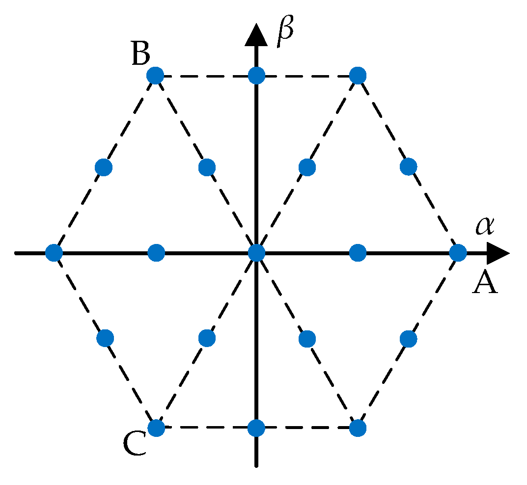
3.1. ECS-MPC

According to the above analysis, reducing the discreteness of the voltage vector distribution within the control set can narrow the gap between the AOVV and the IVV, thus improving the steady-state performance of the conventional FCS-MPC. Therefore, adding more virtual vectors to the control set to construct an ECS is a direct solution.
First, the relationship between the degree of subdivision (DOS) of an ECS and the steady-state performance of the controlled variable, as well as the computational complexity of the algorithm, is investigated. Suppose the DOS of an ECS is m. For ease of presentation, an ECS with DOS m is referred to as an mth-order ECS, following the concept of the matrix order. The 2nd-order ECS is shown as an example in Figure 2.
Focusing on the steady-state performance of current control, the control effect and computational scale of an ECS with different DOSs is simulated and analysed. The simulation conditions are shown in Table 1, and the simulation results are shown in Figure 3.
In Figure 3, ΔTHD (p.u.) is a relative difference of the phase current total harmonic distortion (THD) between ECS-MPCC and DBCC by taking the DBCC phase current THD as the reference for different DOSs, which can be defined as follows,
Δ THD p . u . = Δ THD ECS - MPCC Δ THD DBCC Δ THD DBCC × 100 %
where ΔTHD(ECS-MPCC) is the THD of the ECS-MPCC phase current, and ΔTHD(DBCC) is the THD of the DBCC phase current.
Compu. Scale is the traversal computational scale (TCS) of ECS-MPCC with different DOSs based on the TCS of traditional FCS-MPCC, which can be defined as follows:
Compu .   Scale = TCS ECS - MPCC TCS FCS - MPCC × 100 %
where TCS(ECS-MPCC) is the TCS of the ECS-MPCC method, and TCS(FCS-MPCC) is the TCS of the traditional FCS-MPCC method.
According to the results in Figure 3, in order to balance the steady-state performance and the computational scale, the 16th-order ECS (covered by the red area in Figure 3) is selected as the object of study in this paper.
It should be noted that the current control performance of ECS-MPC is related to the operating state of the motor. The negative effect of the discretization of the ECS-MPC method increases as the magnitude of the IVV decreases, which is because the relative error between the IVV and the AOVV increases as the magnitude of the IVV decreases. This means that the voltage vector error becomes more influential as the IVV decreases, as shown in Figure 4. However, for any magnitude of IVV, it is clear that the error between AOVV and IVV of the ECS-MPC is smaller than that of the conventional FCS-MPC. According to the nature of the regular triangle, the module of maximum error vector (Verror,max) between IVV and AOVV for an m-order ECS can be expressed by the following equation:
V error , max = 3 3 m V basic
where |Vbasic,max| is the module of a basic voltage vector.
According to Equation (8), the Verror,max for the 16th-order ECS is only 1/16 of the conventional FCS. Therefore, the steady-state current control performance of ECS-MPC is still better than that of the conventional FCS-MPC even when the magnitude of the IVV is small.

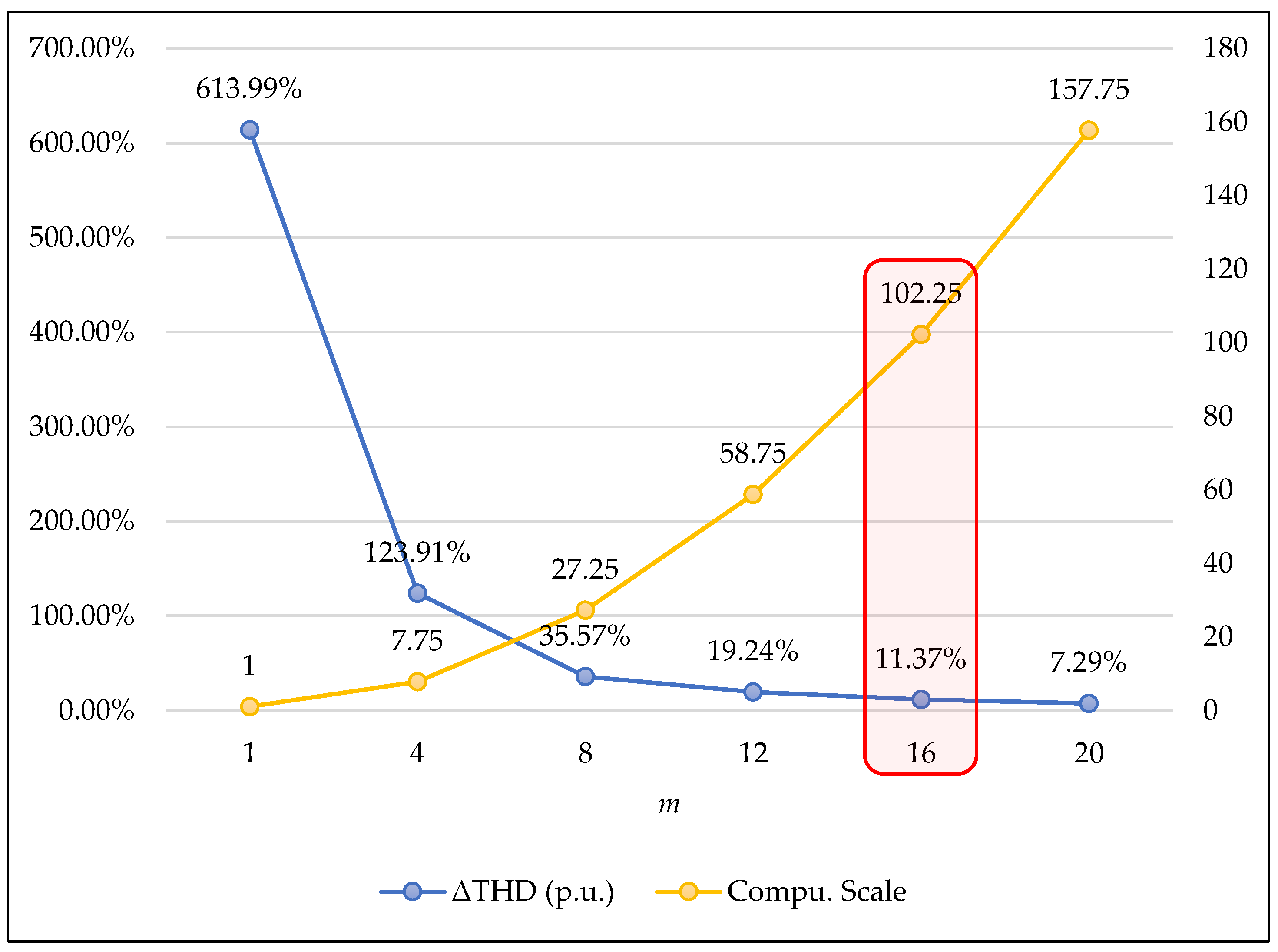
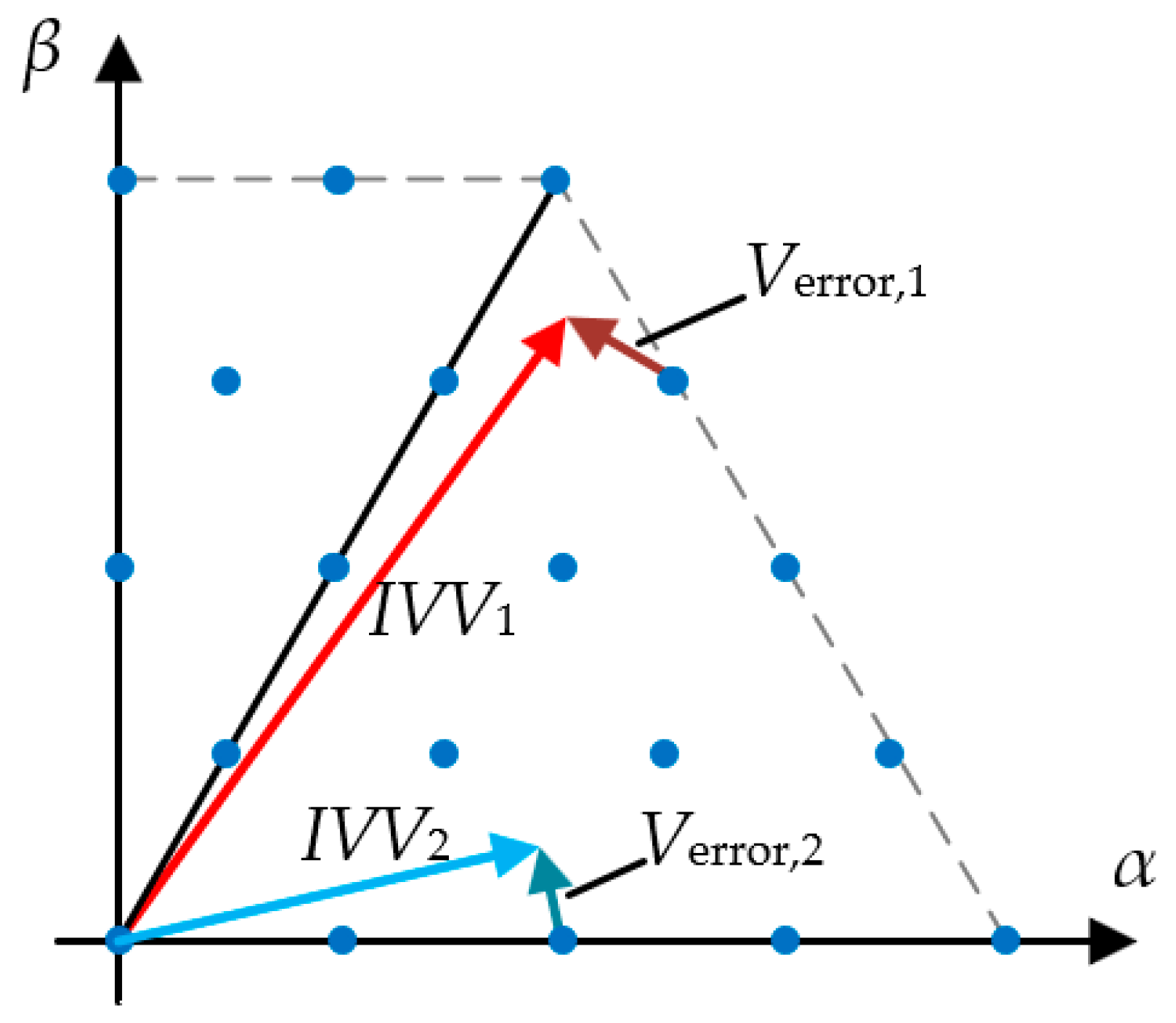
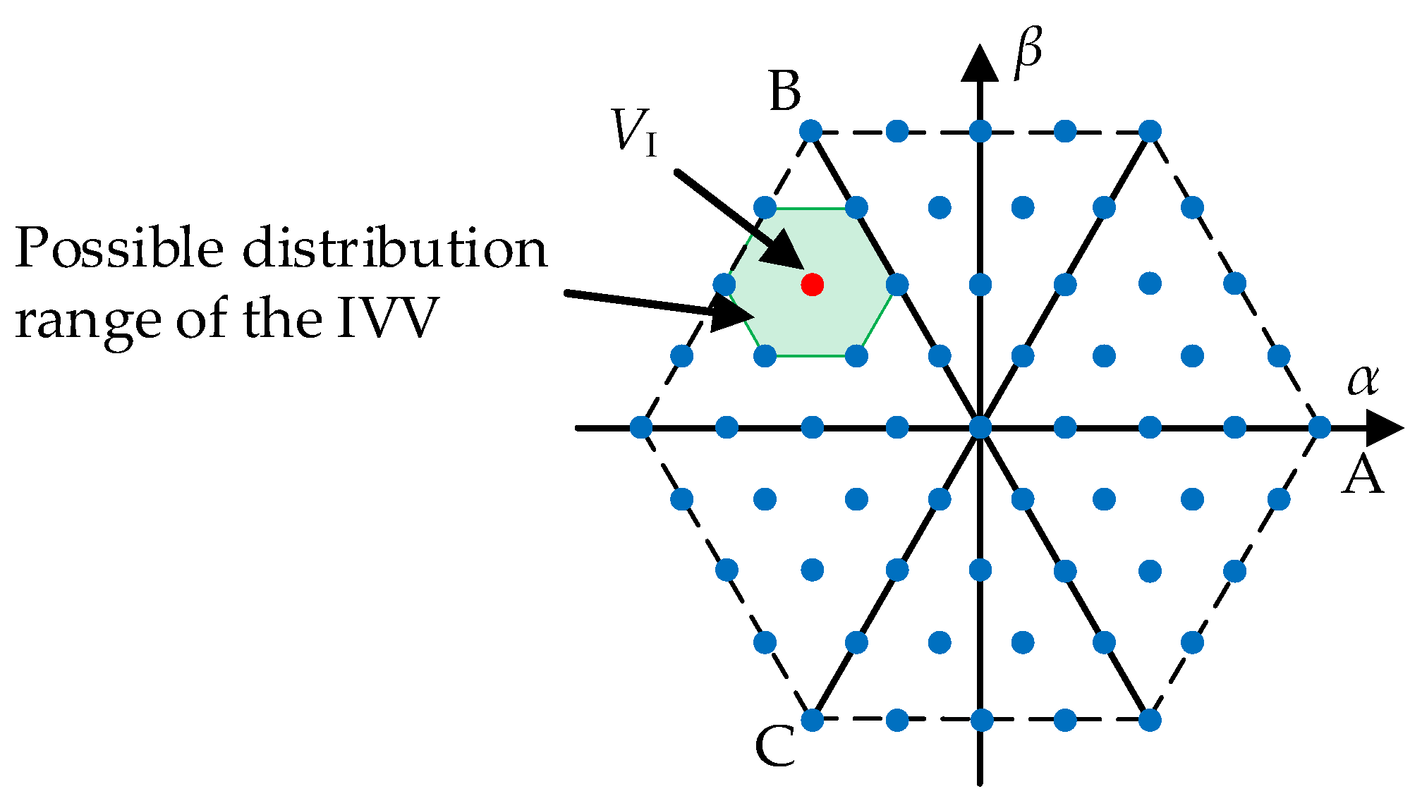
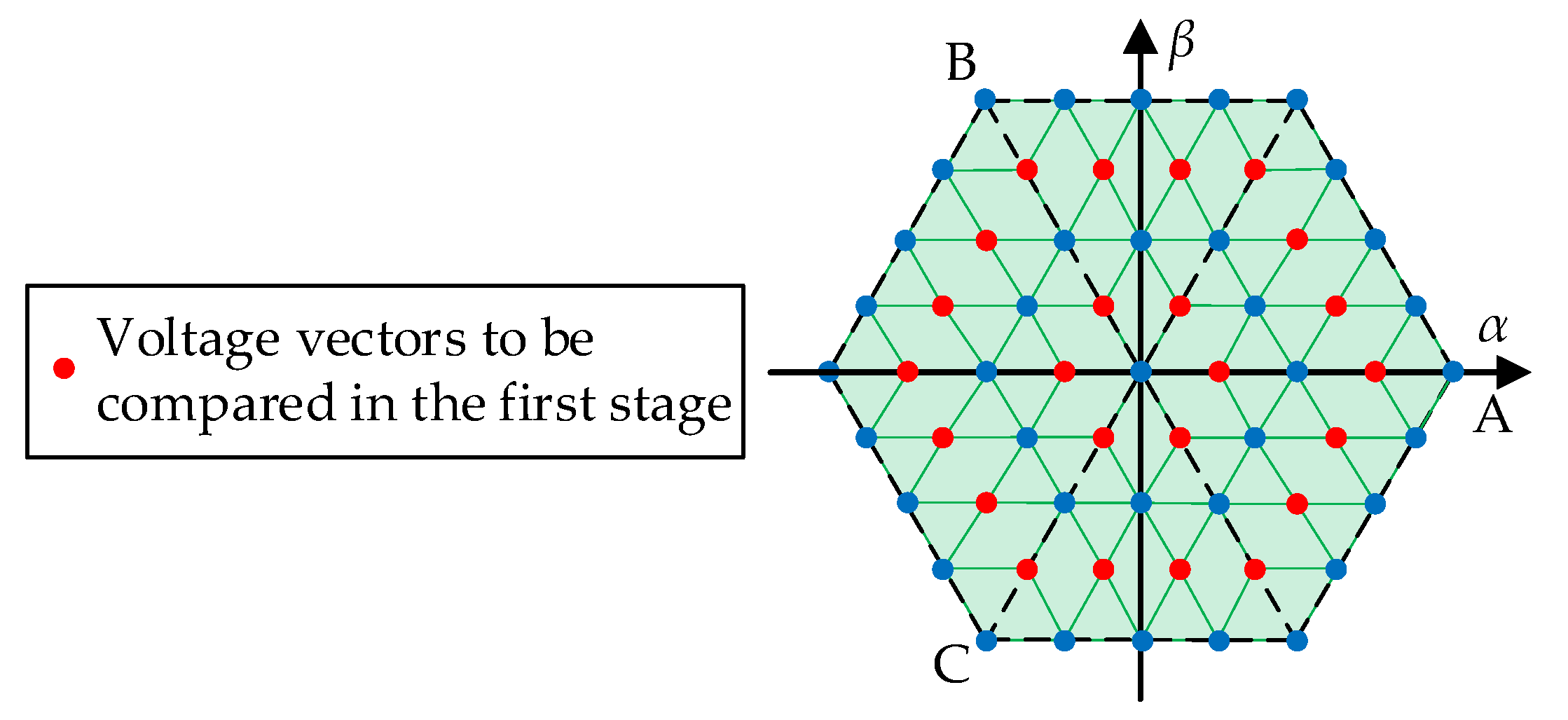
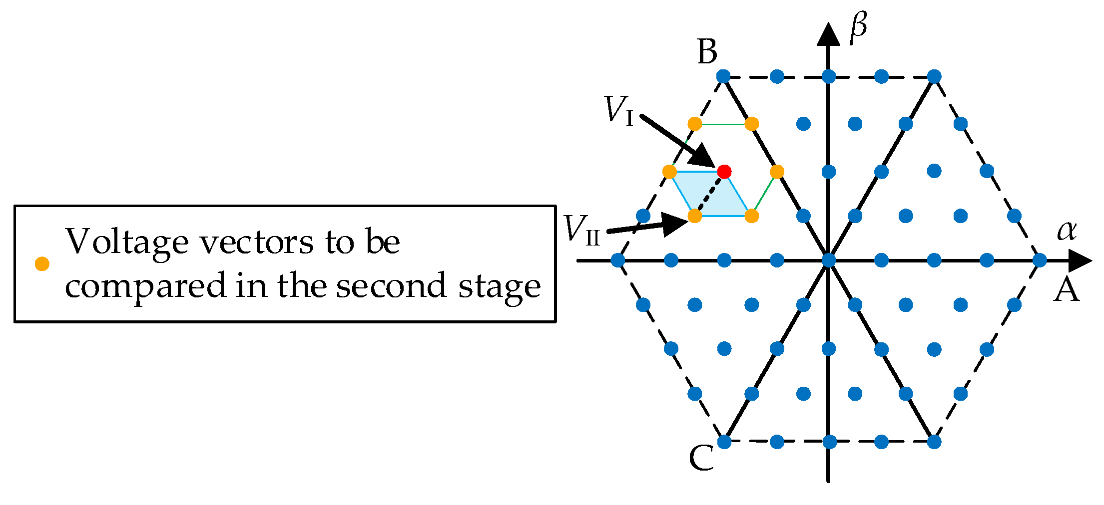
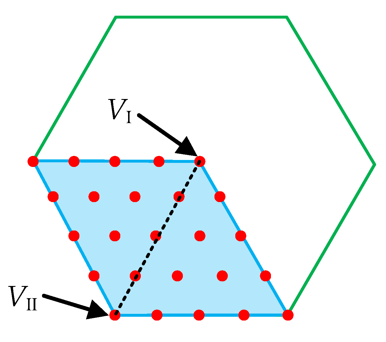
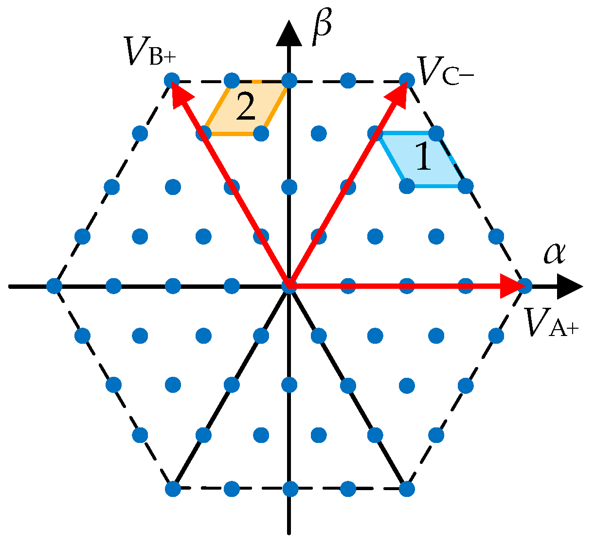
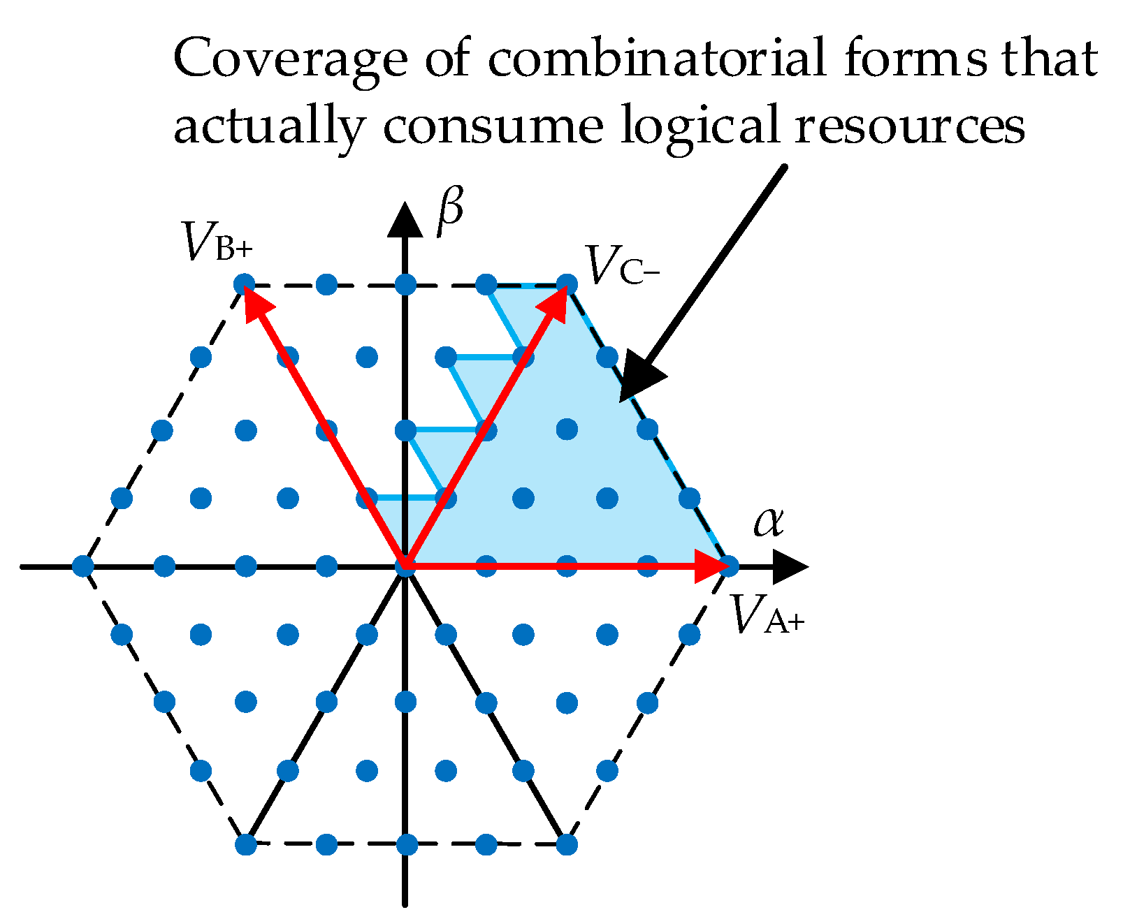
3.2. Simplified Optimal Vector Search Strategy

The 16th-order ECS contains 818 selectable voltage vectors. If all these vectors were to be traversed in each control cycle, it would significantly increase the computational burden on the controller, even to the point of being impossible to complete within one control cycle.
Using the DBC voltage vector as a reference to narrow the traversal range is a feasible strategy [21]. However, since the potential cost function of the DBC has only a single control objective, this strategy is not applicable to multi-objective optimization. To surmount the disadvantages of the DBC reference simplified search strategy (SSS), this paper proposes a novel SSS that takes the cost function value as the only index for narrowing down the search range, which means that even if the cost function contains multiple objects, the proposed SSS will still be effective.
The proposed SSS consists of 3 stages. In the first stage, a 4th-order ECS is generated, where a voltage vector VI corresponding to the smallest value of the cost function exists. Then, the IVV must lie inside the regular hexagon with VI as the center and the other six selectable voltage vectors closest to VI as the vertices, as shown in Figure 5 (if VI is a voltage vector located at the edge, this regular hexagon will be incomplete due to the limitation of the inverter output range).
In fact, as shown in Figure 6, it is already sufficient to compare the cost function values corresponding to only these 24 voltage vectors to cover all the output range of the VSI and narrow down the possible distribution range of the IVV.
In the second stage, after determining the regular hexagon where the IVV is located, the cost function values corresponding to the voltage vectors of the six vertices in this regular hexagon are compared. Supposing the cost function value corresponding to VII is the smallest among these six voltage vectors, the range of possible distribution of IVV can be further narrowed down to a diamond-shaped region with VIVII as the diagonal shown in Figure 7.
In the third stage, the 16th-order ECS voltage vectors to be traversed are generated based on the diamond-shaped region determined above, as shown in Figure 8. Then, these 25 voltage vectors are traversed and the optimal vector is selected according to the principle of minimizing the cost function, similar to the conventional FCS-MPC.
It can be seen that the proposed simplified search strategy reduces the number of voltage vectors to be traversed from 818 to 86 (61 in the first stage and 25 in the third stage), which reduces the algorithm computation by approximately 90%. In addition, the proposed simplified search strategy uses the cost function values as the only filtering index. In both the first and second stages, the possible distribution range of IVV is narrowed down in the most conservative way to avoid missing the global optimal vector. Therefore, the proposed simplified search strategy can be applied to multi-objective integrated control, overcoming the drawbacks of the DBC reference SSS.
The control block diagram of the ECS-MPCC method is shown in Figure 9. In Figure 9, CORDIC represents the coordinate rotation computer that is used to calculate the sine and cosine values for a given angle. After finding the optimal voltage vector, the SVPWM strategy is used to output this voltage vector. Compared with the conventional FCS-MPCC, the main differences are the ECS-MPCC current control blocks which are surrounded by a red area. With the proposed ECS-MPCC method, the error between the IVV and the AOVV is reduced to 1/16 of the conventional method.

4. FPGA Implementation

In this paper, the FPGA is chosen as the controller because its computational characteristics are well suited for the proposed ECS-MPC method. In the implementation of ECS-MPCC, various approaches are used to reduce the computation time and improve resource utilization, which will be illustrated in this section.

4.1. Simplification of the Virtual Voltage Vector Generation Process

In the first and third stages of the execution of the SSS described above, it is necessary to generate the corresponding virtual voltage vectors, i.e., to calculate the dq-axis components of these virtual voltage vectors. In the generation process of virtual voltage vectors in the first stage, if the Park transformation is performed on all these 61 voltage vectors separately, it will consume a lot of computing resources due to the trigonometric operations involved. Since the relative positions of these virtual voltage vectors are invariant, in this paper, only the basic voltage vectors VA+ and VC− in Figure 10 are subjected to the Park transformation, and then their d-axis and q-axis components are linearly combined, respectively, to generate all the voltage vectors needed in the first stage.
For the generation process of virtual voltage vectors in the third stage, due to the excessive number of potential virtual vectors, it would consume a large amount of logic resources to implement these various combinations if only the pair of basic voltage vectors, VA+ and VC−, were used. Considering the property that a regular hexagon has the same shape as the original shape after every 60-degree rotation around the center, in Figure 10, the virtual voltage vectors in region 1 based on the combination forms of VA+ and VC− are exactly the same as the virtual voltage vectors in region 2 based on the combination forms of VC− and VB+. Therefore, in this paper, only the virtual voltage vectors in the region shown in Figure 11 are generated using VA+ and VC−. As for the generation of virtual voltage vectors in other regions, it is only needed to replace VA+ and VC− with corresponding basic voltage vectors. This simplified strategy reduces the logic resource consumption for generating virtual voltage vectors to 1/6 of what it would otherwise be.

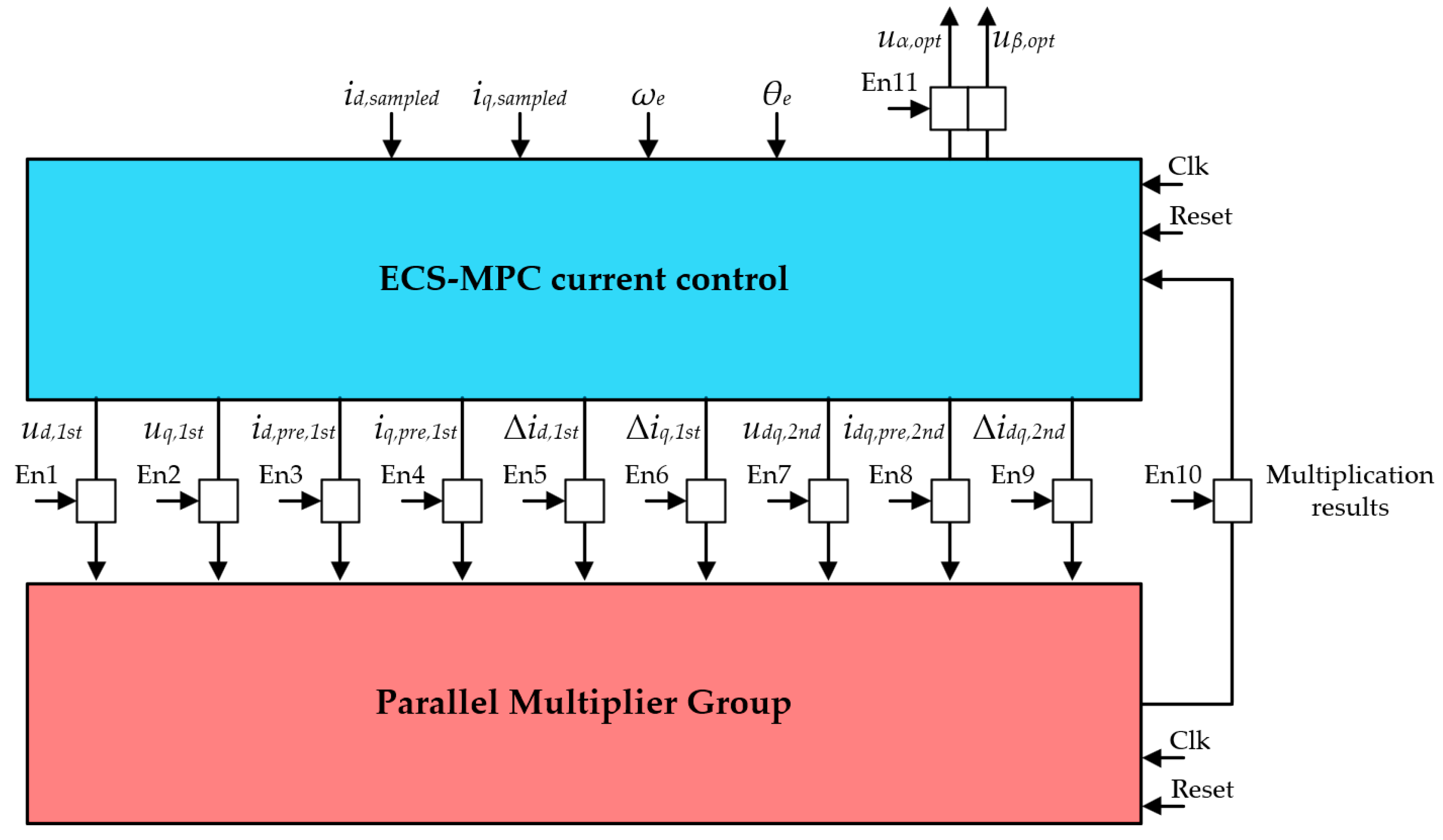
4.2. Parallel Multiplier Group

Obviously, the ECS-MPCC method uses a large number of multipliers to predict the currents and calculate the cost functions. To solve the conflict between reducing multiplier consumption and shortening computation time, a parallel multiplier group (PMG) is constructed on the FPGA system to perform all multiplication operations in the process of predicting currents and calculating cost functions, as shown in Figure 12. Inside the PMG, the time consumption is further reduced by pipelining operations. By using the PMG, the multiplier utilization efficiency is significantly improved by 746% (from 1 multiplier for 1 multiplication operation to 1 multiplier for 8.46 multiplication operations) at the cost of only 0.09 µs (16.7%) increase in computation time (the system clock frequency is 100 MHz). The interconnection between the ECS-MPC current controller and its PMG is shown in Figure 13. There are a series of enable signals to trigger the PMG to perform various multiplicative operations.

4.3. Minimum Filter with Parallel Acceleration

After calculating the values of the cost function corresponding to all selectable voltage vectors, it is necessary to find the minimum value among them. Again, the parallelism of the FPGA is used to accelerate this process. The n-level minimum filter, which consists of multiple 2-input comparators combined and cascaded, is shown in Figure 14. The n-level minimum filter can filter up to 2n inputs for the minimum value after n triggers. The module is configured for double-edge-triggered operation to further accelerate the minimum search process, provided the timing requirements are met. As a result, searching for the minimum of 25 cost function values in the third stage takes only 0.03 µs.

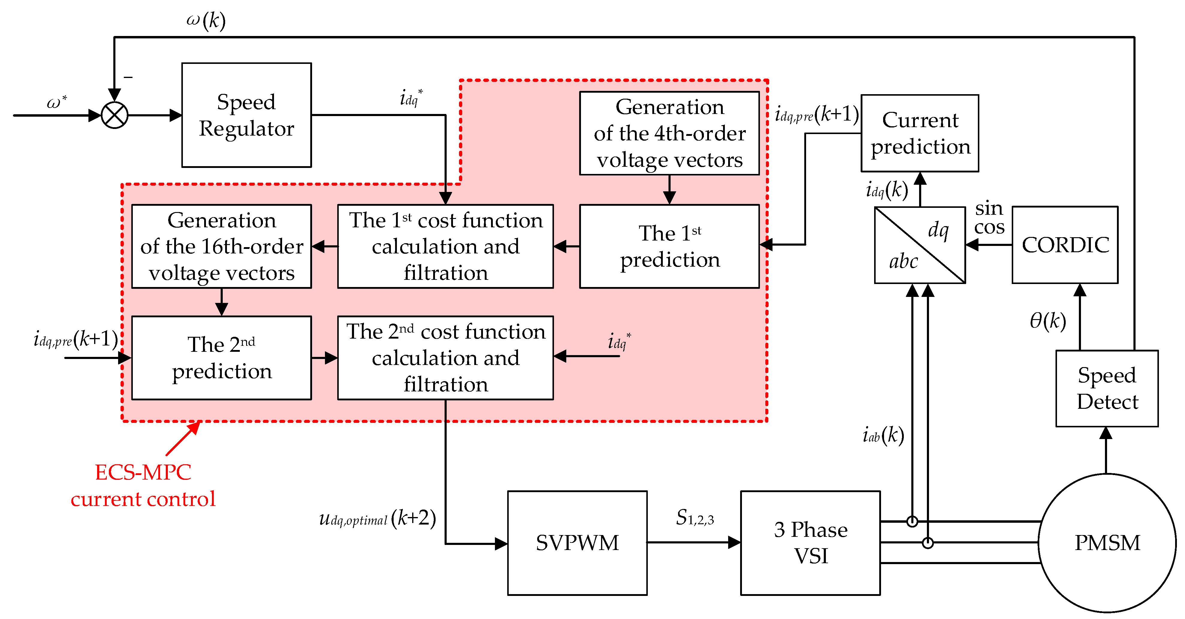
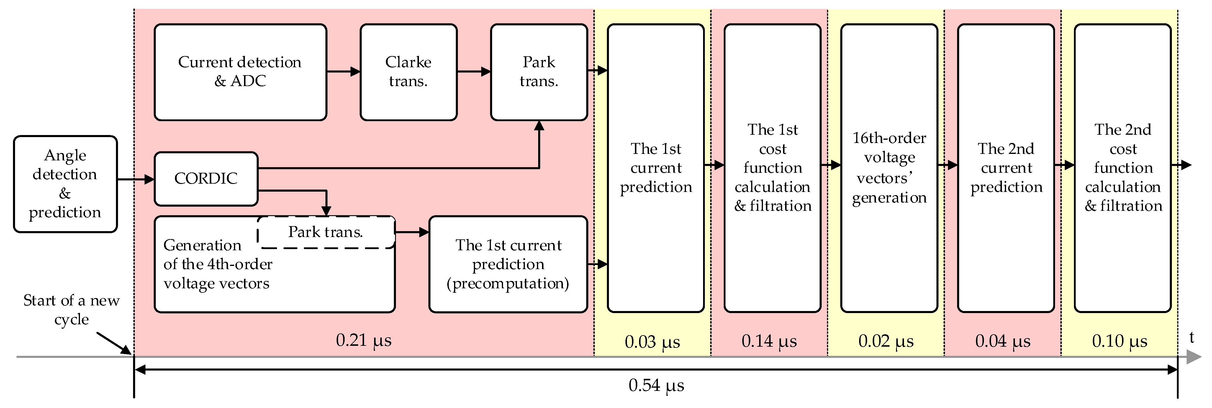
4.4. Overall Structure of the ECS-MPCC

In addition to many hardware-level design optimizations, the overall structure of the ECS-MPCC system is designed to achieve maximum parallelization based on algorithmic logic to further reduce computation time. The structure of the digital implementation of the ECS-MPCC section is shown in Figure 15.
As shown in Figure 15, the ECS-MPCC section takes 0.54 μs. The subsequent inverse Park transformation and SVPWM computation take 0.07 μs. The total control time for the current loop, including current sampling, is therefore only 0.61 μs. At a switching frequency of 20 kHz, the total control time is only 1.22% of the switching cycle, which indicates the high efficiency and performance of the FPGA implementation process.

5. Simulation and Experimental Results

5.1. Simulation and Experimental Conditions

The simulation conditions are basically set according to the actual experimental platform. The main parameters of the motor are already listed in Table 1. The experimental platform is shown in Figure 16. The load of the experimental platform is a generator connected to a braking resistor. The FPGA development board is embedded with a Xilinx ZYNQ 7020 SoC (System on a Chip), but only the FPGA resources of the SoC are used. The inverter module is a TI BOOSTXL-DRV8305EVM. The ADC module samples the A-phase and B-phase currents with a sampling time of 0.08 μs and a resolution of 10 bits. Since the motor studied in this paper is a surface-mounted PMSM (SPMSM), the id = 0 control strategy is used for both simulation and experiment under steady-state conditions. The d-axis target current will have a step change to test the dynamic performance of the proposed method, which refers to the transient performance test in this paper. Simulations and experiments are also performed for the conventional FCS-MPCC and the deadbeat predictive torque control with discrete space vector modulation (DB-PTC with DSVM) proposed in [21]. The torque control strategy proposed in [21] can be equated to a current control strategy (DB-PCC with DSVM) since the motor is an SPMSM.

5.2. Simulation Results

The simulation scenario is that the motor starts with a load of 0.2 N·m and reaches a target speed. To reflect the dynamic performance of the current controller, the d-axis current setpoint is increased from 0 to 4 A at 0.75 s. The waveforms of the A-phase raw current and dq-axis sampled currents under ECS-MPCC, DB-PCC with DSVM and conventional FCS-MPCC are shown in Figure 17. The harmonic analysis results of the A-phase currents are shown in Figure 18. The operating speed in Figure 17 and Figure 18 is 2100 r/min.
As shown in Figure 17 and Figure 18, the proposed ECS-MPCC has the same excellent transient performance as the DB-PCC with DSVM method. However, the THD of the phase current of the ECS-MPCC is significantly lower than that of the other two methods.
Table 2 compares the steady-state performance of these three methods under various speeds and loads. It can be seen that the proposed ECS-MPCC can achieve a lower phase current THD than the other two methods under various speeds and loads.

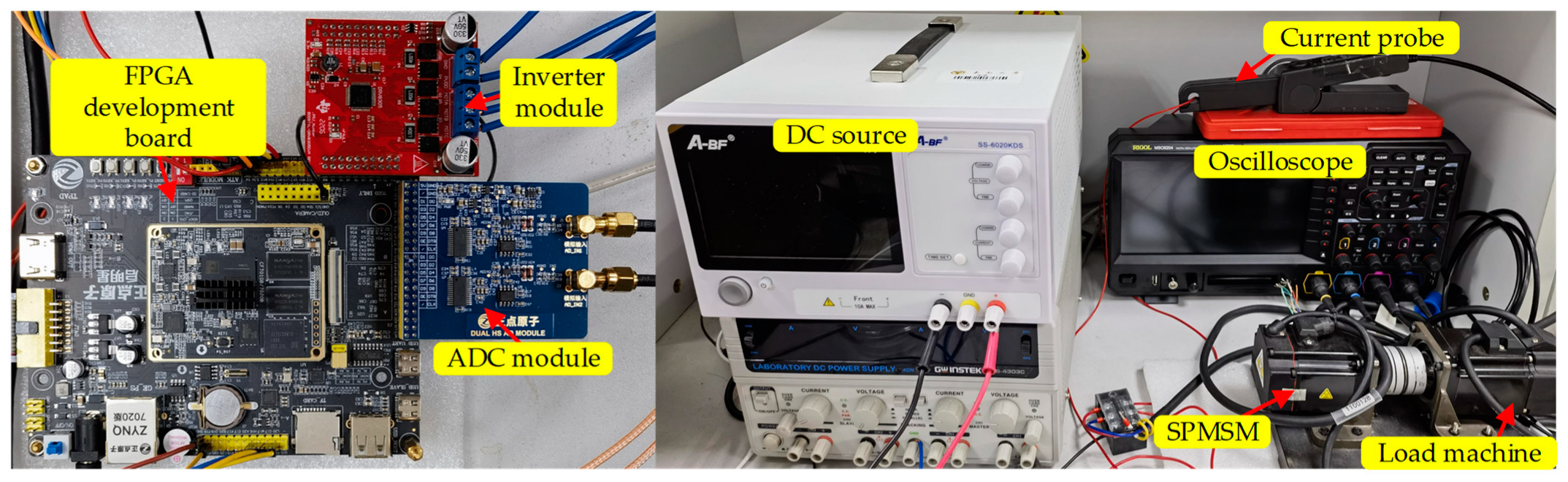
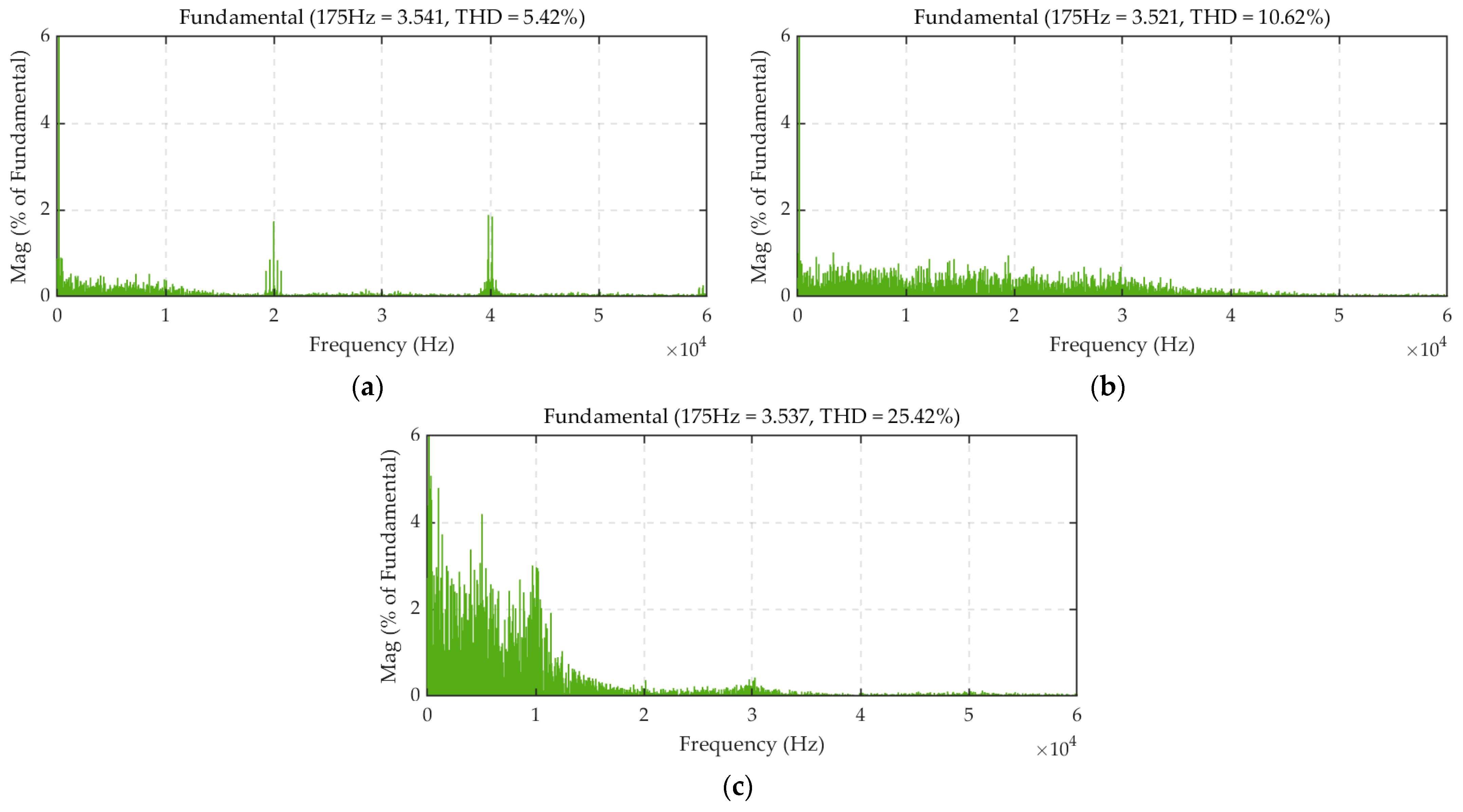
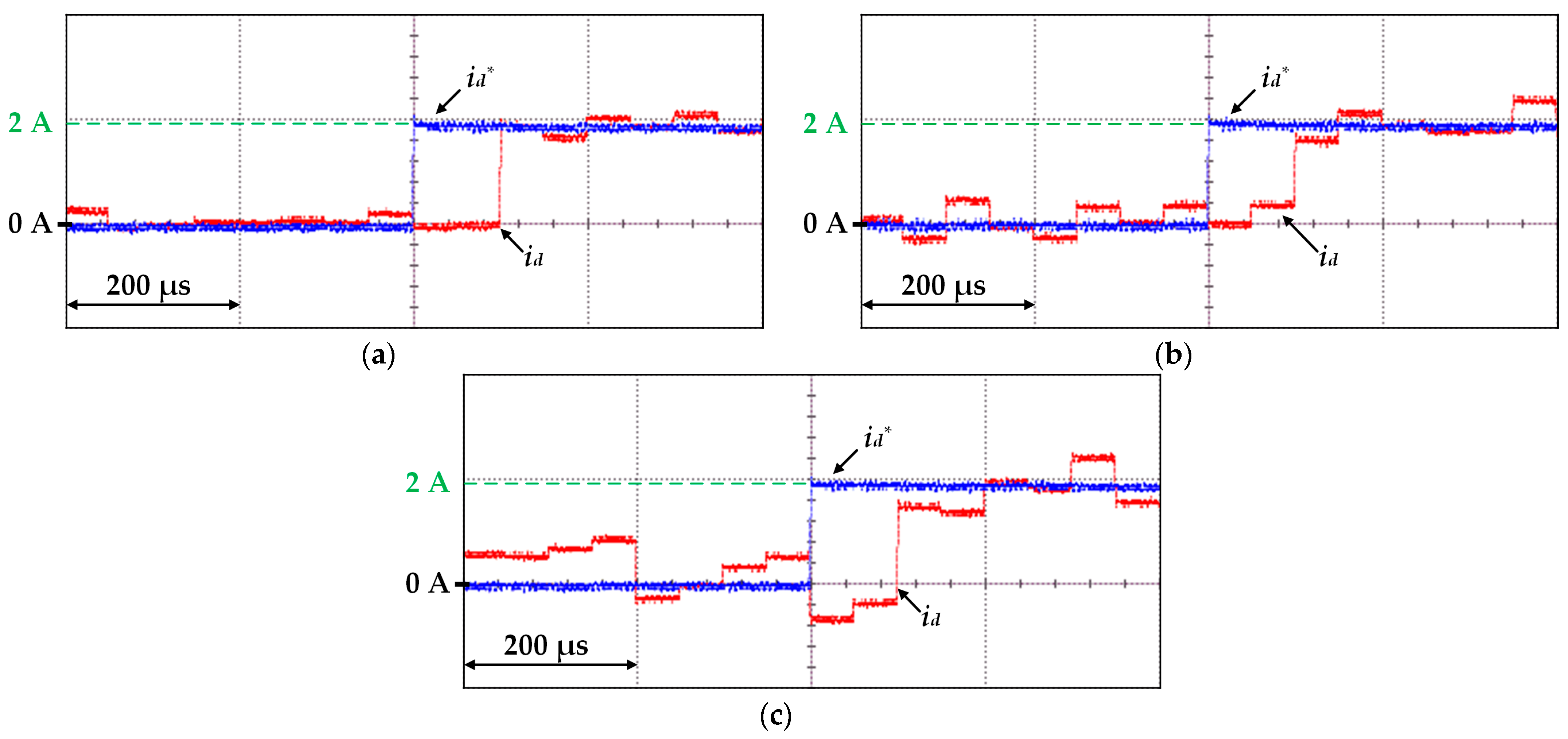
5.3. Experimental Results

The steady-state experiments are conducted under two different operating conditions. The results of the raw A-phase current and dq-axis sampled currents for these three methods are given similarly to the simulation results, as shown from Figure 19, Figure 20, Figure 21 and Figure 22. It is clear that the ECS-MPCC proposed in this paper achieves the best steady-state performance with a current THD only 1/5 of that of the conventional FCS-MPCC. This is because the 16th-order ECS used in this paper contains 818 voltage vectors to ensure that the actual output voltage vector is close enough to IVV. In addition, it can be seen from Figure 20 and Figure 22 that the current low-frequency harmonic contents of the ECS-MPCC proposed in this paper are also the lowest, which can greatly reduce the torque fluctuation and noise during motor operation.
The transient experimental condition is that the q-axis target current is maintained at 4 A while the d-axis target current is switched from 0 to 2 A. Figure 23 shows the d-axis target current and the d-axis sampled current. The values of these two currents are output to an oscilloscope via the DAC module. According to Figure 23, all three methods are able to make the actual current follow the given value within the time of two control cycles. However, the ECS-MPCC is still the best, with minimal fluctuation of the current before and after the jump point.

6. Conclusions

In this paper, an FPGA-based ECS-MPCC with a simplified search strategy and short computational time is proposed. The steady-state performance is significantly improved by constructing an extended control set with 818 voltage vectors. The traversal operation is greatly reduced by using a simplified search strategy applicable to multi-objective optimization. Finally, the ECS-MPCC is implemented using an FPGA controller with current control as the control target. By developing an efficient FPGA-based control system, the total control time of the current loop is reduced to only 0.61 μs. The proposed method follows the vector selection principle of conventional FCS-MPC based on cost function and traversal search, so the potential of multi-objective optimization is inherited from the conventional FCS-MPC.

Author Contributions

Conceptualization, C.Y. and M.H.; methodology, C.Y. and K.L.; software, C.Y.; validation, C.Y. and M.H.; formal analysis, C.Y. and W.H.; investigation, C.Y. and K.L.; resources, W.H. and K.L.; data curation, C.Y.; writing—original draft preparation, C.Y.; writing—review and editing, M.H. and W.H.; visualization, C.Y.; supervision, W.H.; project administration, W.H.; funding acquisition, W.H. All authors have read and agreed to the published version of the manuscript.

Funding

This research was funded by Jiangsu Carbon Peak Carbon Neutralization Science and Technology Innovation Special Fund, grant number BE2022032-1.

Data Availability Statement

Data are contained within the article.

Conflicts of Interest

The authors declare no conflict of interest.

References

  1. Dong, Q.; Liu, X.; Qi, H.; Sun, C.; Wang, Y. Analysis and evaluation of electromagnetic vibration and noise in permanent magnet synchronous motor with rotor step skewing. Sci. China Technol. Sci. 2019, 62, 839–848. [Google Scholar] [CrossRef]
  2. Hu, M.; Hua, W.; Wang, Z.; Li, S.; Wang, P.; Wang, Y. Selective Periodic Disturbance Elimination Using Extended Harmonic State Observer for Smooth Speed Control in PMSM Drives. IEEE Trans. Power Electron. 2022, 37, 13288–13298. [Google Scholar] [CrossRef]
  3. Attaianese, C.; D’Arpino, M.; Monaco, M.D.; Noia, L.P.D. Model-Based Detection and Estimation of DC Offset of Phase Current Sensors for Field Oriented PMSM Drives. IEEE Trans. Ind. Electron. 2023, 70, 6316–6325. [Google Scholar] [CrossRef]
  4. Ahmed, A.A.; Bakeer, A.; Alhelou, H.H.; Siano, P.; Mossa, M.A. A New Modulated Finite Control Set-Model Predictive Control of Quasi-Z-Source Inverter for PMSM Drives. Electronics 2021, 10, 2814. [Google Scholar] [CrossRef]
  5. Huang, J.; Jiang, G.; Zhang, P.; Chen, J. A Low Switching Frequency Model Predictive Control Method for an Induction Motor Fed by a 3-Level Inverter. Electronics 2023, 12, 3609. [Google Scholar] [CrossRef]
  6. Jiang, X.; Yang, Y.; Fan, M.; Ji, A.; Xiao, Y.; Zhang, X.; Zhang, W.; Garcia, C.; Vazquez, S.; Rodriguez, J. An Improved Implicit Model Predictive Current Control with Continuous Control Set for PMSM Drives. IEEE Trans. Transp. Electrif. 2022, 8, 2444–2455. [Google Scholar] [CrossRef]
  7. Anuchin, A.; Demidova, G.L.; Hao, C.; Zharkov, A.; Bogdanov, A.; Šmídl, V. Continuous Control Set Model Predictive Control of a Switch Reluctance Drive Using Lookup Tables. Energies 2020, 13, 3317. [Google Scholar] [CrossRef]
  8. Vu, T.M.; Moezzi, R.; Cyrus, J.; Hlava, J. Model Predictive Control for Autonomous Driving Vehicles. Electronics 2021, 10, 2593. [Google Scholar] [CrossRef]
  9. Comarella, B.V.; Carletti, D.; Yahyaoui, I.; Encarnação, L.F. Theoretical and Experimental Comparative Analysis of Finite Control Set Model Predictive Control Strategies. Electronics 2023, 12, 1482. [Google Scholar] [CrossRef]
  10. She, Y.; Huo, X.; Tong, X.; Wang, C.; Fu, K. Multi-Sampling Rate Finite Control Set Model Predictive Control and Adaptive Method of Single-Phase Inverter. Electronics 2023, 12, 2848. [Google Scholar] [CrossRef]
  11. Yang, H.; Long, H.; Zhang, Q.; Sun, X. A Robust CCS Predictive Current Control for Photovoltaic Energy Storage System Based on a Nonlinear Disturbance Observer. Electronics 2023, 12, 1985. [Google Scholar] [CrossRef]
  12. Lim, C.S.; Lee, S.S.; Levi, E. Continuous-Control-Set Model Predictive Current Control of Asymmetrical Six- Phase Drives Considering System Nonidealities. IEEE Trans. Ind. Electron. 2023, 70, 7615–7626. [Google Scholar] [CrossRef]
  13. Lin, S.; Fang, X.; Wang, X.; Yang, Z.; Lin, F. Multiobjective Model Predictive Current Control Method of Permanent Magnet Synchronous Traction Motors with Multiple Current Bounds in Railway Application. IEEE Trans. Ind. Electron. 2022, 69, 12348–12357. [Google Scholar] [CrossRef]
  14. Wróbel, K.; Serkies, P.; Szabat, K. Continuous and Finite Set Model Predictive Control of Induction Motor Drive. In Proceedings of the IECON 2019-45th Annual Conference of the IEEE Industrial Electronics Society, Lisbon, Portugal, 14–17 October 2019; pp. 963–968. [Google Scholar] [CrossRef]
  15. Vazquez, S.; Rodriguez, J.; Rivera, M.; Franquelo, L.G.; Norambuena, M. Model Predictive Control for Power Converters and Drives: Advances and Trends. IEEE Trans. Ind. Electron. 2017, 64, 935–947. [Google Scholar] [CrossRef]
  16. Agoro, S.; Husain, I. Robust Deadbeat Finite-Set Predictive Current Control with Torque Oscillation and Noise Reduction for PMSM Drives. IEEE Trans. Ind. Appl. 2022, 58, 365–374. [Google Scholar] [CrossRef]
  17. Yang, M.; Lang, X.; Long, J.; Xu, D. Flux Immunity Robust Predictive Current Control with Incremental Model and Extended State Observer for PMSM Drive. IEEE Trans. Power Electron. 2017, 32, 9267–9279. [Google Scholar] [CrossRef]
  18. Zhu, Y.; Tao, B.; Xiao, M.; Yang, G.; Zhang, X.; Lu, K. Luenberger Position Observer Based on Deadbeat-Current Predictive Control for Sensorless PMSM. Electronics 2020, 9, 1325. [Google Scholar] [CrossRef]
  19. Liu, X.; Zhang, Q. Robust Current Predictive Control-Based Equivalent Input Disturbance Approach for PMSM Drive. Electronics 2019, 8, 1034. [Google Scholar] [CrossRef]
  20. Vazquez, S.; Leon, J.I.; Franquelo, L.G. Model Predictive Control with Constant Switching Frequency Using a Discrete Space Vector Modulation with Virtual State Vectors. In Proceedings of the IEEE International Conference on Industrial Technology, Churchill, Australia, 19 May 2009; pp. 1389–1394. [Google Scholar] [CrossRef]
  21. Wang, Y.; Wang, X.; Xie, W.; Wang, F.; Dou, M.; Kennel, R.M.; Lorenz, R.D.; Gerling, D. Deadbeat Model-Predictive Torque Control with Discrete Space-Vector Modulation for PMSM Drives. IEEE Trans. Ind. Electron. 2017, 64, 3537–3547. [Google Scholar] [CrossRef]
  22. Yang, H.; Yang, R.; Hu, W.; Huang, Z. FPGA-Based Sensorless Speed Control of PMSM Using Enhanced Performance Controller Based on the Reduced-Order EKF. IEEE J. Emerg. Sel. Top. Power Electron. 2021, 9, 289–301. [Google Scholar] [CrossRef]
  23. Tu, W.; Luo, G.; Chen, Z.; Liu, C.; Cui, L. FPGA Implementation of Predictive Cascaded Speed and Current Control of PMSM Drives with Two-Time-Scale Optimization. IEEE Trans. Ind. Inform. 2019, 15, 5276–5288. [Google Scholar] [CrossRef]
  24. Milik, A.; Rudnicki, T. A Mixed Hardware-Software Implementation of a High-Performance PMSM Controller. Electronics 2023, 12, 440. [Google Scholar] [CrossRef]
  25. Jnayah, S.; Moussa, I.; Khedher, A. IM Fed by Three-Level Inverter under DTC Strategy Combined with Sliding Mode Theory. Electronics 2022, 11, 3656. [Google Scholar] [CrossRef]
  26. Mishra, I.; Tripathi, R.N.; Singh, V.K.; Hanamoto, T. Step-by-Step Development and Implementation of FS-MPC for a FPGA-Based PMSM Drive System. Electronics 2021, 10, 395. [Google Scholar] [CrossRef]
  27. Mayne, D.Q.; Rawlings, J.B.; Rao, C.V.; Scokaert, P.O.M. Constrained model predictive control: Stability and optimality. Automatica 2000, 36, 789–814. [Google Scholar] [CrossRef]
Figure 1. Comparison of voltage output range of FCS-MPC and DBC.
Electronics 12 04726 g001
Figure 2. The 2nd-order ECS.
Electronics 12 04726 g002
Figure 3. The relationship between the DOS of ECS and the current THD as well as the computational scale of the algorithm.
Electronics 12 04726 g003
Figure 4. The errors between the IVVs and the AOVVs under different operating conditions (using 4th-order ECS as an example).
Electronics 12 04726 g004
Figure 5. Relationship of V and possible distribution range of the IVV.
Electronics 12 04726 g005
Figure 6. Voltage vectors to be compared in the first stage.
Electronics 12 04726 g006
Figure 7. Relationship of VIVII and possible distribution range of the IVV.
Electronics 12 04726 g007
Figure 8. Voltage vectors of the 16th-order ECS to be traversed in the third stage, determined by the combination of VI and VII.
Electronics 12 04726 g008
Figure 9. The control block diagram of the ECS-MPCC method.
Electronics 12 04726 g009
Figure 10. Examples of the three basic voltage vectors of the VSI and two regions with the same basic voltage vector combination form in the third stage.
Electronics 12 04726 g010
Figure 11. Coverage of combinatorial forms that actually consume logical resources.
Electronics 12 04726 g011
Figure 12. Schematic of the PMG application on this FPGA system, with the number of multipliers deployed in each step indicated.
Electronics 12 04726 g012
Figure 13. The interconnection between the ECS-MPC current controller and the PMG.
Electronics 12 04726 g013
Figure 14. The n-level minimum filter with parallel acceleration.
Electronics 12 04726 g014
Figure 15. Digital implementation structure of the ECS-MPCC section.
Electronics 12 04726 g015
Figure 16. Experimental platform.
Electronics 12 04726 g016
Figure 17. Simulation results of the A-phase and dq-axis currents of three MPC methods. (a) ECS-MPCC; (b) DB-PCC with DSVM; (c) conventional FCS-MPCC.
Electronics 12 04726 g017
Figure 18. Harmonic analysis results of the simulation A-phase currents of three MPC methods. (a) ECS-MPCC; (b) DB-PCC with DSVM; (c) conventional FCS-MPCC.
Electronics 12 04726 g018
Figure 19. Steady-state experimental results of the A-phase and dq-axis currents of three MPC methods under the condition of 2100 r/min and iq ≈ 3.5 A. (a) ECS-MPCC; (b) DB-PCC with DSVM; (c) conventional FCS-MPCC.
Electronics 12 04726 g019
Figure 20. Harmonic analysis results of the experimental A-phase currents of three MPC methods under the condition of 2100 r/min and iq ≈ 3.5 A. (a) ECS-MPCC; (b) DB-PCC with DSVM; (c) conventional FCS-MPCC.
Electronics 12 04726 g020
Figure 21. Steady-state experimental results of the A-phase and dq-axis currents of three MPC methods under the condition of 1400 r/min and iq ≈ 2.6 A. (a) ECS-MPCC; (b) DB-PCC with DSVM; (c) conventional FCS-MPCC.
Electronics 12 04726 g021
Figure 22. Harmonic analysis results of the experimental A-phase currents of three MPC methods under the condition of 1400 r/min and iq ≈ 2.6 A. (a) ECS-MPCC; (b) DB-PCC with DSVM; (c) conventional FCS-MPCC.
Electronics 12 04726 g022
Figure 23. Transient experimental results of the dq-axis currents of three MPC methods. (a) ECS-MPCC; (b) DB-PCC with DSVM; (c) conventional FCS-MPCC.
Electronics 12 04726 g023
Table 1. Simulation conditions.
ItemValue
Stator phase resistance Rs (Ω)0.297
Stator d-axis inductance Ld (mH)0.285
Stator q-axis inductance Lq (mH)0.285
Rotor permanent magnet flux ψf (mWb)7.170
Number of pole pairs pn5
DC bus voltage Udc (V)36
Load torque (N⋅m)0.2
Sampling frequency fs (kHz)20
Table 2. The phase current THD of three methods under various speeds and loads.
Load (N·m)Speed (r/min)Phase Current THD
ECS-MPCCDB-PCC with DSVMConventional FCS-MPCC
0.228003.92%7.90%23.31%
21003.82%8.78%24.49%
14003.54%9.30%30.34%
0.128006.18%12.80%36.37%
21006.05%14.73%43.61%
14005.55%17.12%47.55%
Disclaimer/Publisher’s Note: The statements, opinions and data contained in all publications are solely those of the individual author(s) and contributor(s) and not of MDPI and/or the editor(s). MDPI and/or the editor(s) disclaim responsibility for any injury to people or property resulting from any ideas, methods, instructions or products referred to in the content.

