
Model Free Predictive Current Control Based on a Grey Wolf Optimizer for Synchronous Reluctance Motors


1
Mechanical Department, Faculty of Technology, University of Eloued, Eloued 39000, Algeria
2
CISE—Electromechatronic Systems Research Centre, University of Beira Interior, Calçada Fonte do Lameiro, P-6201-001 Covilhã, Portugal
3
LMSE—Laboratoire de Modélisation des Systèmes Energétiques, Université de Biskra, BP 145 R.P., Biskra 07000, Algeria
4
LGEM Laboratoire de Génie Energétique et Matériaux, Université de Biskra, BP 145 R.P., Biskra 07000, Algeria
*
Author to whom correspondence should be addressed.
Electronics 2022, 11(24), 4166; https://doi.org/10.3390/electronics11244166
Submission received: 9 November 2022
/
Revised: 10 December 2022
/
Accepted: 12 December 2022
/
Published: 13 December 2022
(This article belongs to the Special Issue Digital Control of Power Electronics)
Abstract
:A Model-based predictive current control (MBPCC) has recently become a powerful advanced control technology in industrial drives. However, MBPCC relies on the knowledge of the system model and parameters, being, therefore, very sensitive to parameters errors. In the case of the synchronous reluctance motor (SynRM), where the parameters vary due to its ferromagnetic structure and nonlinear magnetic properties, MBPCC performance would suffer significantly. Accordingly, in this paper, a Grey Wolf Optimizer based model-free predictive current control (GW-MFPCC) of SynRM is proposed, to skip all the effects of the model dependency and parameters uncertainty. The proposed method predicts the stator current through tracking the minimum cost function using the grey wolf optimizer. The proposed GW-MFPCC scheme is compared to MBPCC, and its effectiveness is evaluated and confirmed by experimental results.
1. Introduction
In recent years, the synchronous reluctance motor (SynRM) has seen widespread use in many industrial applications due to its simple rotor design, high performance, even at high temperatures, and low cost, making it a strong contender against other established motors in the market [1,2]. On the other hand, with the rapid development of microprocessors, finite-control-set model-based predictive current control (MBPCC) has become a powerful control technology during recent years, which receives more and more interest from the scientific community [3,4,5,6,7,8], due to many advantages, such as simple concept, high dynamic performance, and the ability to easily include multiple nonlinear constraints into a predefined cost function; these characteristics are extremely desired for a wide range of applications [4,7].
Despite the many benefits of MBPCC strategies, they are highly dependent on the system model and parameters [4]. Consequently, such parameter uncertainties negatively affect the control performance, increasing both ripples and tracking errors [3]. In fact, when the motor is operating, the steady-state and dynamic performances will decrease, the current will show a steady-state error, and the noise level increases.
Aside from the limitations of MBPCC, an important point related to SynRMs is the inductances variations caused due to the magnetic material saturation. In fact, an important part of these machines is constructed of ferromagnetic materials with nonlinear magnetic properties that saturate when the total magnetomotive force increases due to an increase in motor currents [9]. Consequently, the SynRM control performance is drastically affected in terms of precision and dynamics. Therefore, the MBPCC’s performance would suffer significantly when the changing parameters were not taken into account [10]. Thus, an accurate MBPCC of the SynRM under magnetic saturation requires a detailed knowledge of the magnetic behavior at different operating conditions. Recently, various predictive schemes were proposed [11,12,13,14], including the magnetic saturation effect of the SynRM, where the inductances evolutions were identified through several experiments, and stored in the main control system as variable quantities, resulting in a time-consuming task and requiring a complex process. Furthermore, they require additional equipment such as measuring instruments and power supplies to obtain the profile of the inductances.
More recently, an advanced predictive concept known as model-free predictive current control (MFPCC) has been proposed as an alternative solution for avoiding the system model and parameters dependency completely. The MFPCC proposed in [15] is based on the detection of current differences. The variations in the current in each of the eight inverter voltage vectors over a switching interval are stored in Lookup tables (LUTs). The content of the LUTs is continuously updated online. However, if the updated LUT frequency is set too low, the method suffers from a stagnation problem, which may have a negative impact on the control performance. Later, similar MFPCC approaches were applied to the SynRM [16,17,18] as well as to the PMSM [19], in an attempt to mitigate the stagnation problem reported in [15]. However, in order to reduce the stagnation issue with the aim of achieving satisfactory performance, these approaches require high sampling frequencies, which further necessitate the use of very fast and expensive digital processors.
Another MFPCC approach based on an ultra-local model has been proposed for PMSM drives [20,21] and DFIG drives [22]. The method only considers the system’s input and output, which are built from known and unknown interference terms. However, these terms are induced by parameter changes as well as nonlinearity properties. This kind of method suffers from poor control performance at low sampling frequencies as well as complex tuning work, whereas mentioned in [23], that the MFPCC based on Ultra local model needs five parameters for tuning and a computational time of 44.76 µs is required, while the MBPCC in the same paper needs 36.97 µs. The improved version of this method is employed then by combining the ultra-local method with an extended state observer [23,24], which adds further complexity and computation on the already non intuitive control approach, amplifying the adverse effects of the MFPCC.
Other recent methods, as illustrated in [25,26,27], use the recursive least squares (RLS) algorithm, which is an adaptive filter mechanism for avoiding the impacts of parameters. However, these approaches in [26,27] do not address the difference in computing time between the standard MBPCC and the MFPCC based on RLS algorithms, although [25] shows that the MFPCC based on RLS has a slower dynamic compared to the MBPCC for different cases.
According to the author’s knowledge, only a few studies report on the usage of MFPCC rather than the usual MBPCC based on the parameters. Furthermore, most MFPCC schemes suffer either from high computation time or algorithm complexity also poor control performance. Therefore, developing a new approach to derive the current prediction can overcome the issues previously mentioned.
Nowadays, grey wolf optimizer (GWO) is a new heuristic strategy [28] that mimics the grey wolf community hierarchy and hunting mechanisms. The GWO has the advantages of low computational complexity, convergence independence of starting conditions and high solution accuracy, among others. These characteristics inspired researchers to use it in order to improve classical vector control techniques of electrical drives [29,30,31,32]. However, the use of GWO in the advanced predictive control with the aim to avoid the system model and parameters dependency is not yet reported in the literature. Accordingly, in this paper, a new model-free predictive current control based on a grey wolf optimizer (GW-MFPCC) for SynRM drives is developed and proposed. The proposed control scheme relies on a discrete model-free that predicts future current behavior by tracking the minimum error between the reference and predicted currents by imposing a new factor that is not related to the machine parameters, where the GWO searches for the optimum value of the imposed factor. On the other hand, unlike [25], the proposed technique would satisfy high dynamics due to the GWO’s fast convergence and robustness. Furthermore, as an alternative to [23], neither extensive tuning effort nor a high computational burden is required, making the proposed method of control simple and intuitive. The performance of the proposed GW-MFPCC is evaluated and confirmed by means of intensive experimental results.
2. Model Based Predictive Control
The aim behind MBPCC is to use a machine model to forecast the future behavior of the system and to pick the next control action based on a specific optimum criterion. Therefore, by ignoring the effects of magnetic saturation and iron losses, the SynRM model in the synchronous dq reference frame is defined as:
where vdq and idq are the voltages and currents in the dq-axes, respectively. Rs is the stator resistance; Ld and Lq are the d-axis and q-axis inductance, respectively, and the ωe is the electrical rotor speed. Taking into account that the magnet path in the d-axis is iron dominant and excitation sensitive, while the magnetic path in the q-axis is air dominant and not excitation sensitive, Ld and Lq values are different. As previously mentioned, inductances may vary due to the magnetic saturation effect. Moreover, the temperature rise, and the load condition may cause variations in the resistance. Thus, taking these variations into account, (1) can be rewritten as follows:
where the variation values of the parameters are denoted by ∆. It can be verified from (2) that the resistance variation has a very small effect on the dynamic model accuracy and, in fact, its error can be neglected. However, errors in the inductance values have a more serious effect [16]. As a result, using the model in (2) for MBPCC will be time-consuming and necessitate detailed knowledge of the magnetic behavior under various operating conditions. Therefore, according to (1) and using the standard Euler approximation, the discrete currents at the control period (k + 1)th is given by:
where Ts is the sampling interval and vdqk are constructed from the optimal voltage vector applied at the instant kth. In a real-time implementation, the control algorithm’s computation time causes a one-step time delay which must be compensated [33]. Therefore, instead of and instead of will be predicted at the (k + 2)th control period:
where is computed from (3) and is constructed from the possible eight voltage vectors that the power converter can synthesize. Then, the cost function evaluates the error between the forecast currents and their references, defined as:
where the reference current is generated by the speed controller, while is derived from considering the maximum torque per ampere (MTPA) strategy in [34,35], given by:
It should be mentioned that there are eight different conduction modes. Each one corresponds to a different combination of inverter voltages that yields predicted current values. The optimum conduction mode Sj, which provides the minimum cost value from (5), can be calculated as follows:
The optimal conduction mode satisfying (7) will be used to control the inverter’s six IGBTs in the next sampling period.
3. Model Free Predictive Current Control
In conventional MBPCC, the current prediction is mainly dependent on the parameter’s accuracy. In fact, obtaining accurate SynRM parameters values is impossible [16]. Therefore, to avoid the effects of parameters mismatches, a new GW-MFPCC is proposed, which relies on a GWO to track the minimum cost function, thus benefiting from the GWO advantages, namely, the high solution accuracy, quick convergence, low tuning and computational efforts, and the ability to deal with local optimum [28,29,30].
3.1. Proposed GW-MFPCC
In the case of MBPCC, the expression (3) can be simplified via omitting the term RsTs/Ls, by assuming that the sampling time is very small [36]. On the other hand, when an optimum input factor Xopt = 1/Ldq is imposed, as in (8), the second term in (3) has no effect on the choice of the optimum voltage vector from the eight possible vectors and therefore it can be ignored. In (8), a discrete model-free of machine parameters is represented using the simplified expression from (3), with the aim to develop a model unrelated to any machine model and parameters, defined as:
where Xopt denotes the optimum input factor. The search for the optimum value Xopt is based on the GWO, which can guarantee a suitable current prediction. In a similar way to (4), the dq-axes currents should be predicted at the (k + 2)th sampling period, using the following expression:
In contrast to the MBPCC using (1)–(4), the GW-MFPCC in (8) and (9) does not use any machine model or parameter. Then, the optimal voltage vector of the GW-MFPCC is selected by evaluating and minimizing the cost function as in (5) and (7), respectively, and considering the MTPA strategy defined in (6), in a similar way to the MBPCC.
3.2. Grey Wolf Optimizer
With the purpose of finding the optimum factor Xopt, the GWO is implemented. The GWO is a new swarm intelligence algorithm that mimics the social and hunting behavior of grey wolves. The wolves’ society has a strict hierarchical system, divided into four groups, as shown in Figure 1a, where the leaders wolves called α, who represent the optimal solution; β and δ wolves giving assistance to leaders in the decision-making process, denoting the second and third most suitable solutions; and ω wolves behaving as followers of the order [28].
The procedure of hunting the prey, in other words, searching for the optimum factor Xopt is in the following:
First, an initialization step is required, which involves determining the number of grey wolves Ng and the maximum number of iterations Mi for searching over one sampling period, as well as the lower and upper boundaries defined as Lb and Ub, respectively, that characterize the search space of the input factor X, which contains the Xopt that will overcome the need for parameters in the MBPCC for SynRM. Then, choosing the candidate objective function, which is in this case the minimum cost function, defined as:
In (10), the fitness chooses the lower value of min g between the current sampling period and the previous period to reinforce the wolves for finding the optimum factor Xopt.
In the second step, encircling the prey, each wolf group (α, β, and δ) is allowed to locate the possible target of the prey in order to search for it. The potential wolves’ locations are regarded as the best initial probable solutions in relation to the optimal factor Xopt. During the hunt, the grey wolves encircle their prey, which can be expressed mathematically as:
where n is the actual iteration number. is the prey and is the position vector of the wolf search agent, in other words, the actual value of the input factor. represents the distance between the grey wolf and the prey, while and denote the control coefficients which can be calculated as follows:
The and are random vectors within [0, 1], and is linearly decreased from 2 to 0 while the iterations increased.
The third step is the location update, which is depicted in Figure 1b. The hunting process is guided by α, β, and δ wolves’ groups that are close to the prey and guide the ω wolves group to move. The following equations describe the hunting mechanism and the updating process:
where , , and are their distance vectors with ω wolves, respectively; and , , and are the movement instructions given by α, β, and δ, respectively. When the value of is greater than 1 or less than −1, the wolves will move away from the known prey in order to find a more suitable target (exploration mechanism), that will enable the GWO algorithm to search globally. Moreover, the values of are randomly distributed between 0 and 2, which will enhance exploration throughout the whole process. Through the equations above, the wolves update their positions in the next iteration n + 1 using the following equation:
The final step is the attacking step, which occurs when the wolves converge on the prey, which happens until the maximum number of iterations Mi is reached. The best wolf position to the prey is the Xα, employed then as Xopt in (8) and (9), in order to achieve an appropriate current prediction that corresponds to the minimum cost function. The flowchart of the proposed GWO algorithm is depicted in Figure 2.
It should be noted that the GWO’s exploration mechanism will prevent Xopt from becoming stuck at one optimum value. Consequently, as opposed to MFPCC methods in [15,17,18,24], the proposed method has a low tuning effort, simple structure, intuitive, and fast optimization process. The control diagram of the SynRM drive system based on the proposed method is shown in Figure 3.
4. Simulation and Experimental Results
The modeling and simulation of the SynRM drive system, and the proposed control schemes were carried out in Matlab/Simulink environment. The machine dynamic model takes into account the magnetic saturation and iron losses, as described in [35]. Table 1 shows the parameters of the SynRM. Moreover, the experimental test rig comprises basically a 2.2 kW SynRM (with the same parameters reported in Table 1) coupled to an AC load machine, a Powerex POW-R-PAK voltage source inverter, a diode bridge rectifier, and the dSPACE DS1103 digital controller. Figure 4 shows the experimental setup.
4.1. Tuning and Computational Efforts
The proposed GW-MFPCC and the classical MBPCC algorithms are implemented under Matlab/Simulink environment, into the dSPACE digital controller using a sampling period of Ts = 45 µs. Table 2 provides a detailed comparison of complexity between both control algorithms. In comparison to conventional MBPCC, which require precise SynRM parameters that may change due to several reasons, the proposed GW−MFPCC requires few constant parameters. The parameters required are in Table A1 in the Appendix A. It must be noticed that these parameters values are chosen as optimal values that allow the best possible performance.
Regarding the computational time, the proposed GW−MFPCC algorithm takes 28.5 μs to complete the code in each Ts, which is slightly higher than the classical MBPCC, which takes 25.9 μs. The execution time difference in the proposed method is mainly due to the number of iterations Mi in each Ts, as well as the number of wolf search agents Ng. Indeed, such slight increase in computational time is quite acceptable considering the significant contribution offered by the GW-MFPCC. It is important to emphasize that the GW-MFPCC does not require neither extensive tuning work as in [21,22], nor extensive computational effort as in [19].
4.2. Control Performance
To evaluate the control performance, the total harmonic distortion (THD) and the total waveform oscillation (TWO) are employed, defined as:
where xRMS and xdc stand for the RMS and average values, respectively.
The proposed GW-MFPCC is compared to the traditional MBPCC with and without accurate SynRM parameters. For a fair comparison, both control schemes have been tuned in order to give the best possible performance, and they are tested under the same conditions.
Figure 5 presents the simulation results of the conventional MBPCC and the proposed model-free GW-MFPCC considering the same operating conditions. First, the reference speed is set to 800 rpm/s under a load torque of 2 N.m. Then, at the instant t = 0.5 s, the reference speed increases to 1200 rpm/s, whereas at the instant t = 1 s the load torque steps to 12 N.m. The performance of the MBPCC with nominal parameters is illustrated in Figure 5a, where the first and second figures show the actual and zoomed SynRM currents, respectively, the third figure illustrates the dq-axes currents and their references, and the last figure presents the rotor speed together with its reference value. Analyzing the results, it is clearly observed that even with the nominal parameters of the MBPCC, an obvious deviation is aroused in the q-axis current compared to its reference, which increases as the speed and load torque increase. The MBPCC is sensitive to parameter variations; therefore, the tracking q-axis current error increases even more under inductances variations, where the dq-axes inductances values are set lower than their nominal values (see Figure 5b). As a result, high current ripples and harmonic distortions are obtained, especially under inductances variations. It is important to emphasize that the inductances variation is performed by changing their values in the MBPCC algorithm. On the contrary, since the proposed GW-MFPCC does not require the knowledge of the motor parameters, the tracking error of q-axis current is eliminated, showing an inherent immunity against the SynRM parameter variations. Thus, although both control schemes can achieve a fast dynamic response and provide a similar rotor speed performance, the considered GW-MFPCC performs better in harmonic distortion. The zoomed figures of the steady-states show that the GW-MFPCC in Figure 5c provides a similar sinusoidal current waveform to the MBPCC with nominal parameters shown in Figure 5a, with a slight difference in THD value. It can be also seen that the dq-axes currents smoothly follow their new references with high accuracy in both control schemes, while the GW−MFPCC d-axis current provides better performance with a lower TWO value, and slightly lower q-axis current performance with a minor difference in TWO values compared to MBPCC with nominal parameters. From the considered control strategies, it can be concluded that the MBPCC with inductance variations has the lowest performance by presenting the highest THD and TWO values, while the proposed GW-MFPCC shows the similar performance of the MBPCC with accurate parameters under all the considered operating conditions.
Figure 6 shows the three phase currents, d-axis current, q-axis current, and the rotor speed at 1100 rpm, under a load torque of 5 Nm. The results of MBPCC with optimal parameters are seen in Figure 6a. Since the MBPCC is highly dependent on the SynRM parameters that may vary due to the magnetic saturation effect and operating condition, optimal parameters can be inaccurate. The MBPCC performance under inaccurate parameters is shown in Figure 6b. Since inductance uncertainty has a greater impact on control performance than resistance uncertainty, the dq-axes inductances are set lower than their optimal values in the MBPCC algorithm. The experimental results of the proposed GW-MFPCC are seen in Figure 6c, where the system model and parameters are totally eliminated.
In terms of rotor speed performance, all control strategies are relatively similar. In terms of three-phase currents steady-state performance, the GW-MFPCC performs very similarly to the MBPCC with optimal parameters, albeit with a small difference in THD values. The GW-MFPCC outperforms the MBPCC in aspects of d-axis current and offers marginally lower q-axis current performance to the MBPCC with optimal parameters, showing a slight difference in TWO value, as well as perfect reference tracking capabilities. However, because the MBPCC is very sensitive to parameter variations, it can be observed an obvious offset between the actual and reference q-axis current when mismatched inductances are considered, resulting in poor tracking capability performance. It can be also seen that the d-axis current presents higher ripple content than the one corresponding to the other control techniques. Therefore, the experimental results confirm the effectiveness of the proposed GW-MFPCC in suppressing the influence of parameters variations in SynRM.
Another steady-state experimental test is carried out, and the three-phase currents, d-axis current, q-axis current, and rotor speed, are shown in Figure 7 at 800 rpm and 14 Nm load torque.
All control techniques perform similarly in terms of rotor speed. In terms of three-phase current steady-state performance, the MBPCC with nominal parameters (see Figure 7a) performs similar manner to the GW-MFPCC (see Figure 7c), with a minor difference in THD values, such as the one in the preceding figure. In terms of d,q currents, the GW-MFPCC surpasses the MBPCC in d-axis current aspects while offering significantly poorer q-axis current performance to the MBPCC with optimal parameters, exhibiting a tiny difference in TWO value as well as excellent reference tracking capabilities. Nonetheless, due to the MBPCC’s sensitivity to parameter variations, an obvious offset between the actual and reference q-axis current can be noticed when mismatched inductances are considered (see Figure 7b), resulting in poor tracking capability performance. It can also be noticed that the d-axis current has a larger ripple content than the currents associated with the other control methods. Furthermore, under 14 Nm, the rated torque condition, the suggested technique uses less current than the MBPCC with mismatched parameters.
To better evaluate the dynamic performance of the considered control strategies, comparative tests are conducted and shown in Figure 8, where a load torque is instantaneously applied at the instant t = 0.5 s from no-load to 5 Nm, under a constant speed reference of 600 rpm. It can be observed that all the control strategies can achieve a fast dynamic response and that the rotor speed tracks its reference with good stability and accuracy after a slight drop due to the load step. Regarding the performance of currents, the zoomed figures of the steady-states show that the proposed GW-MFPCC has sinusoidal current waveforms, similar to the ones of the MBPCC with nominal parameters, with a slight difference in THD values (see Figure 8a,c). It is obvious that the GW-MFPCC performs better than the MBPCC in terms of d-axis current performance under the steady state, providing smooth and close tracking of the reference. On the other hand, the GW-MFPCC, has slightly lower q-axis performance than the MBPCC, with a tiny difference in TWO, but it offers perfect reference tracking capabilities. On the contrary, since the MBPCC is highly dependent on accurate parameters, sinusoidal current waveforms cannot be achieved when mismatched inductances are assumed, as shown in Figure 8b, allowing a poor THD performance. The dq-axes currents have the worst steady-state ripples, resulting in high TWO values, and a significant offset in the q-axis current was observed, which increases as the load torque increases. From the considered control strategies, it can be concluded that the MBPCC performance with incorrect parameters degrades more and more as the load torque increases, while the proposed GW−MFPCC shows a high immunity against the SynRM parameter variations and a great robustness against strong and fast load torque variations.
To further evaluate the dynamic performance of the proposed GW-MFPCC, a speed variation under a constant load torque of 2 Nm is considered, as shown in Figure 9. At the instant t = 0.5 s, the reference speed is changed from 500 rpm to 1000 rpm with an acceleration rate of 1000 rpm/s. It can be seen that all control strategies exhibit a similar rapid dynamic response for the considered operation conditions, showcasing good and precise speed tracking capability with no significant overshoot. The zoomed figures of the steady-states show that the GW-MFPCC in Figure 9c provides a similar sinusoidal current waveform to the MBPCC with nominal parameters shown in Figure 9a, with a slight difference in THD value. It can be also seen that the dq-axes currents smoothly follow their new references with high accuracy in both control schemes, while the GW-MFPCC d-axis current provides better performance with a lower TWO value, and slightly lower q-axis current performance with a minor difference in TWO values compared to MBPCC with nominal parameters. However, parameter uncertainties negatively affect the MBPCC, causing tracking errors and affecting the control performance, as depicted in Figure 9b. Once again, the MBPCC with mismatched inductances has the lowest performance by presenting the highest THD and TWO values. Sinusoidal current waveforms cannot be shaped at high rotor speed. Moreover, ripples and an obvious deviation from the reference are aroused in the dq-axes currents, showing this way the MBPCC high dependency on accurate parameters. Hence, it can be concluded the importance of the proposed model-free GW-MFPCC in abandoning the system model and avoiding the parameters variations effect.
5. Conclusions
This paper proposes a new model-free predictive current control based on real-time currents using GWO. The proposed control scheme has two main processes:
(1) The proposed discrete model is devoid of machine parameters and does not necessitate knowledge of motor parameters, which need only the optimum factor to generate the dq-axis currents predictions, thus avoiding the influence of parameter variations;
(2) The cost function evaluates the error between the reference and forecast currents, and the GWO then tracks the minimum cost function to give the optimum value of the imposed factor at the next sampling time.
The proposed model-free GW-MFPCC is compared to the conventional MBPCC. The simulation and experimental results showed that both control schemes had excellent dynamic performance. However, as opposed to the MBPCC, which is susceptible to suffering from parameter variations, the proposed GW-MFPCC was not affected by the motor parameters and could achieve better steady-state performance. Furthermore, the proposed method’s tracking ability confirms its robustness, while the small difference in execution times between the proposed method and the MBPCC (25.5 for the MBPCC and 28.5 for the GW-MFPCC) indicates the method’s efficiency compared to other MFPCC methods.
The results confirm the effectiveness of the proposed method by presenting the best overall performance in terms of current ripples and tracking errors under various operating conditions. From the presented results, it can be concluded that the proposed technique may be useful as a good alternative to model-based predictive schemes when the motor manufacturer does not provide adequate motor data and self-commissioning processes are difficult to implement.
Author Contributions
Conceptualization, A.M. and I.J.; methodology, A.M., A.J.M.C., I.J. and K.Y.; formal analysis, A.M., A.J.M.C. and I.J.; investigation, A.M. and I.J.; resources, A.J.M.C.; data curation, A.M.; writing—original draft preparation, A.M.; writing—review and editing, A.M., I.J., A.J.M.C. and K.Y.; visualization, A.M., I.J. and A.J.M.C. and K.Y.; supervision, I.J., A.J.M.C. and K.Y.; project administration, A.J.M.C.; funding acquisition, A.J.M.C. All authors have read and agreed to the published version of the manuscript.
Funding
This work was supported by the European Regional Development Fund (ERDF) through the Operational Programme for Competitiveness and Internationalization (COMPETE 2020), under Project POCI-01-0145-FEDER-029494, and by National Funds through the FCT—Portuguese Foundation for Science and Technology, under Projects PTDC/EEI-EEE/29494/2017, UIDB/04131/2020, and UIDP/04131/2020.
Conflicts of Interest
The authors declare no conflict of interest.
Abbreviations and Symbols
The following abbreviations and Symbols are used in this manuscript:
| MBPCC | Model Based Predictive Current Control |
| SynRM | Synchronous Reluctance Motor |
| MFPCC | Model Free Predictive Current Control |
| GWO | Grey Wolf Optimizer |
| GW-MFPCC | Grey Wolf Optimizer Based Model Free Predictive Current Control |
| vdq | The Voltages in the dq- axes |
| idq | The Currents in the dq-axes |
| Rs | The stator resistance |
| Ld, Lq | The d-axis and q-axis inductances |
| ωe | The electrical rotor speed |
| ∆ | The variation values of the parameters |
| Ts | The sampling interval |
| g | The Cost Function |
| id*,iq* | The reference Currens of the dq axes |
| MTPA | The maximum torque per ampere |
| Xopt | The Optimum Input Factor |
| α, β, δ and ω | Wolves Groupes |
| Ng | The number of grey wolves |
| Mi | The maximum number of iterations |
| The distance between the grey wolf and the prey | |
| and | The Control Coefficient |
| The Position Vector of the search Agent | |
| The Prey | |
| n | Actual iteration number |
Appendix A

Table A1.
The Optimal values of GW-MFPCC.
| Parameter | Value |
|---|---|
| Mi | 4 |
| Lb | 0 |
| Ub | 10 |
| Ng | 4 |
References
- Fratta, A.; Vagati, A. A reluctance motor drive for high dynamic performance application. IEEE Trans. Ind. Appl. 1992, 28, 873–879. [Google Scholar] [CrossRef]
- Matsuo, T.; Lipo, T. Rotor design optimization of synchronous reluctance machine. IEEE Trans. Energy Convers. 1994, 9, 359–365. [Google Scholar] [CrossRef]
- Vazquez, S.; Rodriguez, J.; Rivera, M.; Franquelo, L.G.; Norambuena, M. Model Predictive Control for Power Converters and Drives: Advances and Trends. IEEE Trans. Ind. Electron. 2017, 64, 935–947. [Google Scholar] [CrossRef] [Green Version]
- Cortes, P.; Kazmierkowski, M.P.; Kennel, R.M.; Quevedo, D.E.; Rodriguez, J. Predictive Control in Power Electronics and Drives. IEEE Trans. Ind. Electron. 2008, 55, 4312–4324. [Google Scholar] [CrossRef]
- Jlassi, I.; Cardoso, A.J.M. Enhanced and Computationally Efficient Model Predictive Flux and Power Control of PMSG Drives for Wind Turbine Applications. IEEE Trans. Ind. Electron. 2021, 68, 6574–6583. [Google Scholar] [CrossRef]
- Jlassi, I.; Cardoso, A.J.M. Lookup-Table-Based Model Predictive Torque Control Without Weighting Factors for PMSM Drives. In Proceedings of the IECON 2019—45th Annual Conference of the IEEE Industrial Electronics Society, Lisbon, Portugal, 14–17 October 2019; Volume 1, pp. 1165–1170. [Google Scholar] [CrossRef]
- Jlassi, I.; Cardoso, A.J.M. Open-circuit fault-tolerant operation of permanent magnet synchronous generator drives for wind turbine systems using a computationally efficient model predictive current control. IET Electr. Power Appl. 2021, 15, 837–846. [Google Scholar] [CrossRef]
- Gmati, B.; Jlassi, I.; El Khil, S.K.; Cardoso, A.J.M. Open-switch fault diagnosis in voltage source inverters of PMSM drives using predictive current errors and fuzzy logic approach. IET Power Electron. 2021, 14, 1059–1072. [Google Scholar] [CrossRef]
- Lubin, T.; Razik, H.; Rezzoug, A. Magnetic saturation effects on the control of a synchronous reluctance machine. IEEE Trans. Energy Convers. 2002, 17, 356–362. [Google Scholar] [CrossRef] [Green Version]
- Young, H.A.; Perez, M.A.; Rodriguez, J. Analysis of Finite-Control-Set Model Predictive Current Control with Model Parameter Mismatch in a Three-Phase Inverter. IEEE Trans. Ind. Electron. 2016, 63, 3100–3107. [Google Scholar] [CrossRef]
- Morales-Caporal, R.; Pacas, M. Suppression of Saturation Effects in a Sensorless Predictive Controlled Synchronous Reluctance Machine Based on Voltage Space Phasor Injections. IEEE Trans. Ind. Electron. 2010, 58, 2809–2817. [Google Scholar] [CrossRef]
- Morales-Caporal, R.; Pacas, M. Encoderless Predictive Direct Torque Control for Synchronous Reluctance Machines at Very Low and Zero Speed. IEEE Trans. Ind. Electron. 2008, 55, 4408–4416. [Google Scholar] [CrossRef]
- Morales-Caporal, R.; Pacas, M. A Predictive Torque Control for the Synchronous Reluctance Machine Taking into Account the Magnetic Cross Saturation. IEEE Trans. Ind. Electron. 2007, 54, 1161–1167. [Google Scholar] [CrossRef]
- Jlassi, I.; Cardoso, A.J.M. Model Predictive Current Control of Synchronous Reluctance Motors, Including Saturation and Iron Losses. In Proceedings of the XIII International Conference on Electrical Machines (ICEM), Alexandroupoli, Greece, 3–6 September 2018; pp. 1598–1603. [Google Scholar]
- Lin, C.-K.; Liu, T.-H.; Yu, J.-T.; Fu, L.-C.; Hsiao, C.-F. Model-Free Predictive Current Control for Interior Permanent-Magnet Synchronous Motor Drives Based on Current Difference Detection Technique. IEEE Trans. Ind. Electron. 2013, 61, 667–681. [Google Scholar] [CrossRef]
- Lin, C.-K.; Yu, J.-T.; Lai, Y.-S.; Yu, H.-C. Improved Model-Free Predictive Current Control for Synchronous Reluctance Motor Drives. IEEE Trans. Ind. Electron. 2016, 63, 3942–3953. [Google Scholar] [CrossRef]
- Da Ru, D.; Polato, M.; Bolognani, S. Model-free predictive current control for a SynRM drive based on an effective update of measured current responses. In Proceedings of the 2017 IEEE International Symposium on Predictive Control of Electrical Drives and Power Electronics (PRECEDE), Pilsen, Czech Republic, 4–6 September 2017; pp. 119–124. [Google Scholar] [CrossRef]
- Carlet, P.G.; Tinazzi, F.; Bolognani, S.; Zigliotto, M. An Effective Model-Free Predictive Current Control for Synchronous Reluctance Motor Drives. IEEE Trans. Ind. Appl. 2019, 55, 3781–3790. [Google Scholar] [CrossRef] [Green Version]
- Ma, C.; Li, H.; Yao, X.; Zhang, Z.; De Belie, F. An Improved Model-Free Predictive Current Control with Advanced Current Gradient Updating Mechanism. IEEE Trans. Ind. Electron. 2020, 68, 11968–11979. [Google Scholar] [CrossRef]
- Xu, L.; Chen, G.; Li, Q. Ultra-Local Model-Free Predictive Current Control Based on Nonlinear Disturbance Compensation for Permanent Magnet Synchronous Motor. IEEE Access 2020, 8, 127690–127699. [Google Scholar] [CrossRef]
- Zhou, Y.; Li, H.; Liu, R.; Mao, J. Continuous Voltage Vector Model-Free Predictive Current Control of Surface Mounted Permanent Magnet Synchronous Motor. IEEE Trans. Energy Convers. 2018, 34, 899–908. [Google Scholar] [CrossRef]
- Zhang, Y.; Jiang, T.; Jiao, J. Model-Free Predictive Current Control of a DFIG Using an Ultra-Local Model for Grid Synchronization and Power Regulation. IEEE Trans. Energy Convers. 2020, 35, 2269–2280. [Google Scholar] [CrossRef]
- Zhang, Y.; Jin, J.; Huang, L. Model-Free Predictive Current Control of PMSM Drives Based on Extended State Observer Using Ultralocal Model. IEEE Trans. Ind. Electron. 2020, 68, 993–1003. [Google Scholar] [CrossRef]
- Zhang, Y.; Jiang, T.; Jiao, J. Model-Free Predictive Current Control of DFIG Based on an Extended State Observer Under Unbalanced and Distorted Grid. IEEE Trans. Power Electron. 2020, 35, 8130–8139. [Google Scholar] [CrossRef]
- De Martin, I.D.; Pasqualotto, D.; Tinazzi, F.; Zigliotto, M. Model-Free Predictive Current Control of Synchronous Reluctance Motor Drives for Pump Applications. Machines 2021, 9, 217. [Google Scholar] [CrossRef]
- Tinazzi, F.; Carlet, P.G.; Bolognani, S.; Zigliotto, M. Motor Parameter-Free Predictive Current Control of Synchronous Motors by Recursive Least-Square Self-Commissioning Model. IEEE Trans. Ind. Electron. 2019, 67, 9093–9100. [Google Scholar] [CrossRef]
- Saeed, M.S.; Song, W.; Yu, B. Robustness Improvement of Deadbeat Model Predictive Control for Five-phase PMSM Drives. In Proceedings of the 2020 15th IEEE Conference on Industrial Electronics and Applications (ICIEA), Kristiansand, Norway, 9–13 November 2020; IEEE: Piscataway, NJ, USA, 2020. [Google Scholar]
- Mirjalili, S.; Mirjalili, S.M.; Lewis, A. Grey Wolf Optimizer. Adv. Eng. Softw. 2014, 69, 46–61. [Google Scholar] [CrossRef] [Green Version]
- Qais, M.H.; Hasanien, H.M.; Alghuwainem, S. A Grey Wolf Optimizer for Optimum Parameters of Multiple PI Controllers of a Grid-Connected PMSG Driven by Variable Speed Wind Turbine. IEEE Access 2018, 6, 44120–44128. [Google Scholar] [CrossRef]
- Sun, X.; Jin, Z.; Cai, Y.; Yang, Z.; Chen, L. Grey Wolf Optimization Algorithm Based State Feedback Control for a Bearingless Permanent Magnet Synchronous Machine. IEEE Trans. Power Electron. 2020, 35, 13631–13640. [Google Scholar] [CrossRef]
- Sun, X.; Hu, C.; Lei, G.; Guo, Y.; Zhu, J. State Feedback Control for a PM Hub Motor Based on Gray Wolf Optimization Algorithm. IEEE Trans. Power Electron. 2019, 35, 1136–1146. [Google Scholar] [CrossRef]
- Djerioui, A.; Houari, A.; Ait-Ahmed, M.; Benkhoris, M.-F.; Chouder, A.; Machmoum, M. Grey Wolf based control for speed ripple reduction at low speed operation of PMSM drives. ISA Trans. 2018, 74, 111–119. [Google Scholar] [CrossRef]
- Cortes, P.; Rodriguez, J.; Silva, C.; Flores, A. Delay Compensation in Model Predictive Current Control of a Three-Phase Inverter. IEEE Trans. Ind. Electron. 2011, 59, 1323–1325. [Google Scholar] [CrossRef]
- Matos, D.; Estima, J.O.; Yahia, K.; Cardoso, A.J.M. Modeling and Implementation of MTPA Control Strategy for SynRM Variable Speed Drives. Int. Rev. Electr. Eng. (IREE) 2014, 9, 1103. [Google Scholar] [CrossRef]
- Yahia, K.; Matos, D.; Estima, J.O.; Cardoso, A.J.M. Modeling synchronous reluctance motors including saturation, iron losses and mechanical losses. In Proceedings of the 2014 International Symposium on Power Electronics, Electrical Drives, Automation and Motion, Ischia, Italy, 18–20 June 2014; pp. 601–606. [Google Scholar]
- Cortes, P.; Rodríguez, J.; Quevedo, D.; Silva, C. Predictive Current Control Strategy with Imposed Load Current Spectrum. IEEE Trans. Power Electron. 2008, 23, 612–618. [Google Scholar] [CrossRef]
Figure 1.
(a) Hierarchy of grey wolf (dominance decreases from top to down). (b) Grey wolf’s position update.
Figure 1.
(a) Hierarchy of grey wolf (dominance decreases from top to down). (b) Grey wolf’s position update.
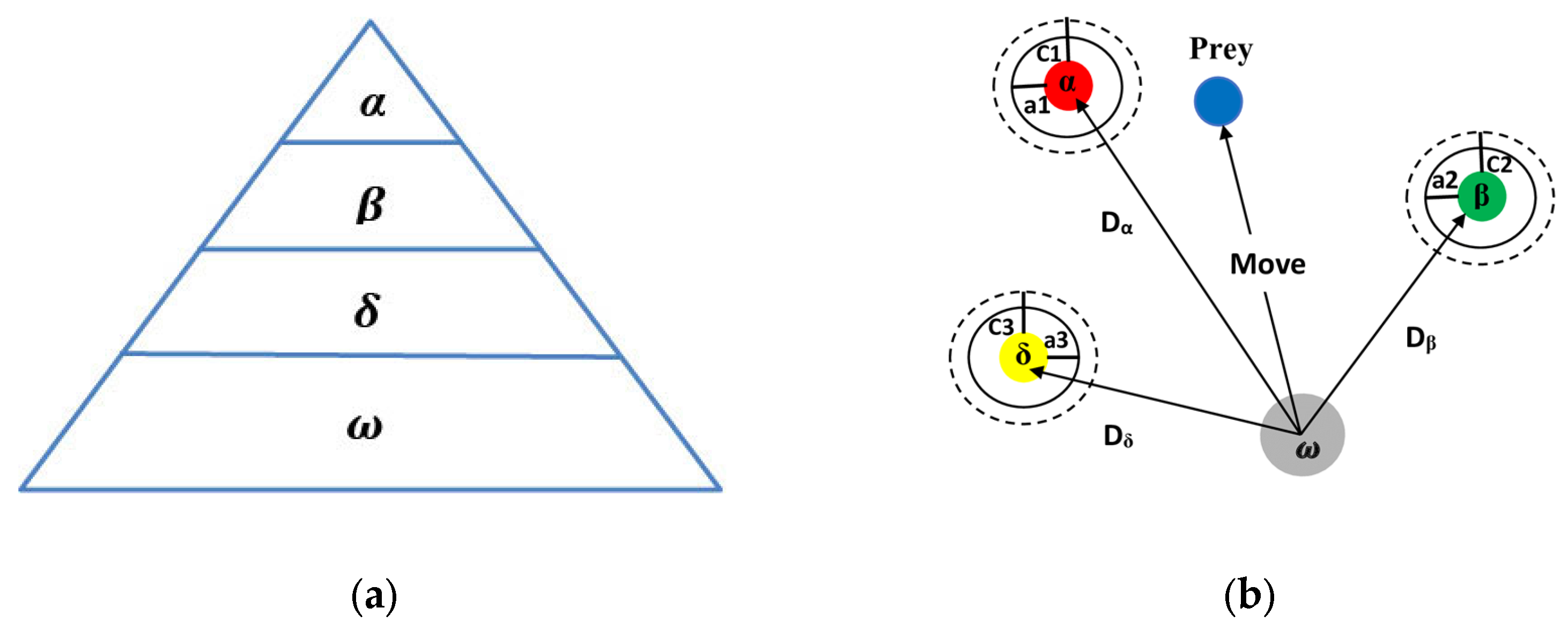
Figure 2.
Flowchart of the proposed GWO algorithm.
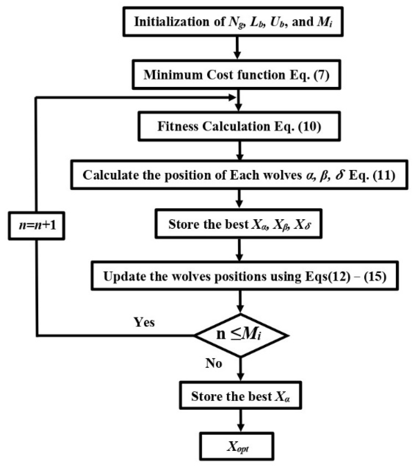
Figure 3.
Control Diagram of the SynRM drive system with GW-MFPCC.
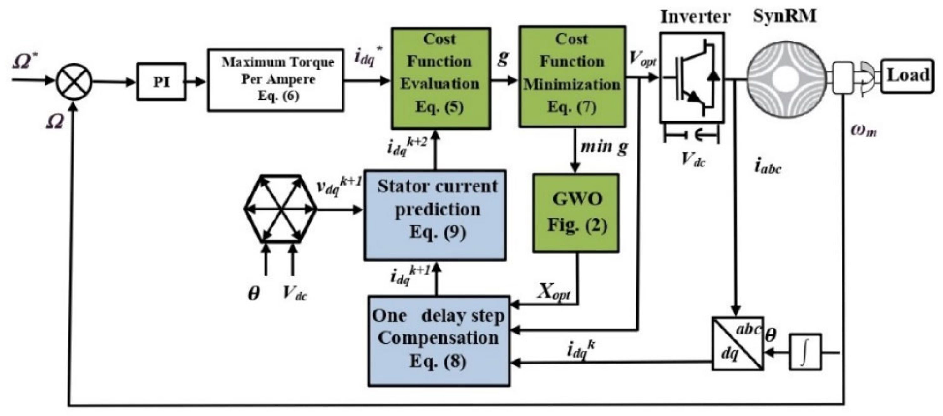
Figure 4.
Experimental Setup.
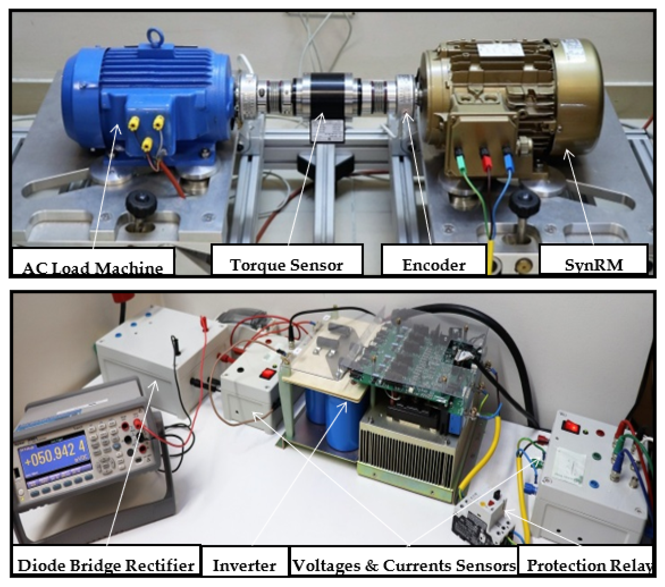
Figure 5.
Simulation Results under speed and load variation. (a) MBPCC with nominal parameters, (b) MBPCC under the influence of parameter variations (0.5xLd, 0.5xLq), (c) proposed GW−MFPCC.
Figure 5.
Simulation Results under speed and load variation. (a) MBPCC with nominal parameters, (b) MBPCC under the influence of parameter variations (0.5xLd, 0.5xLq), (c) proposed GW−MFPCC.

Figure 6.
Experimental results for 1100 rpm and 5 Nm: (a) MBPCC with nominal parameters, (b) MBPCC under the influence of parameter variations (0.5xLd, 0.5xLq), (c) proposed GW−MFPCC.
Figure 6.
Experimental results for 1100 rpm and 5 Nm: (a) MBPCC with nominal parameters, (b) MBPCC under the influence of parameter variations (0.5xLd, 0.5xLq), (c) proposed GW−MFPCC.
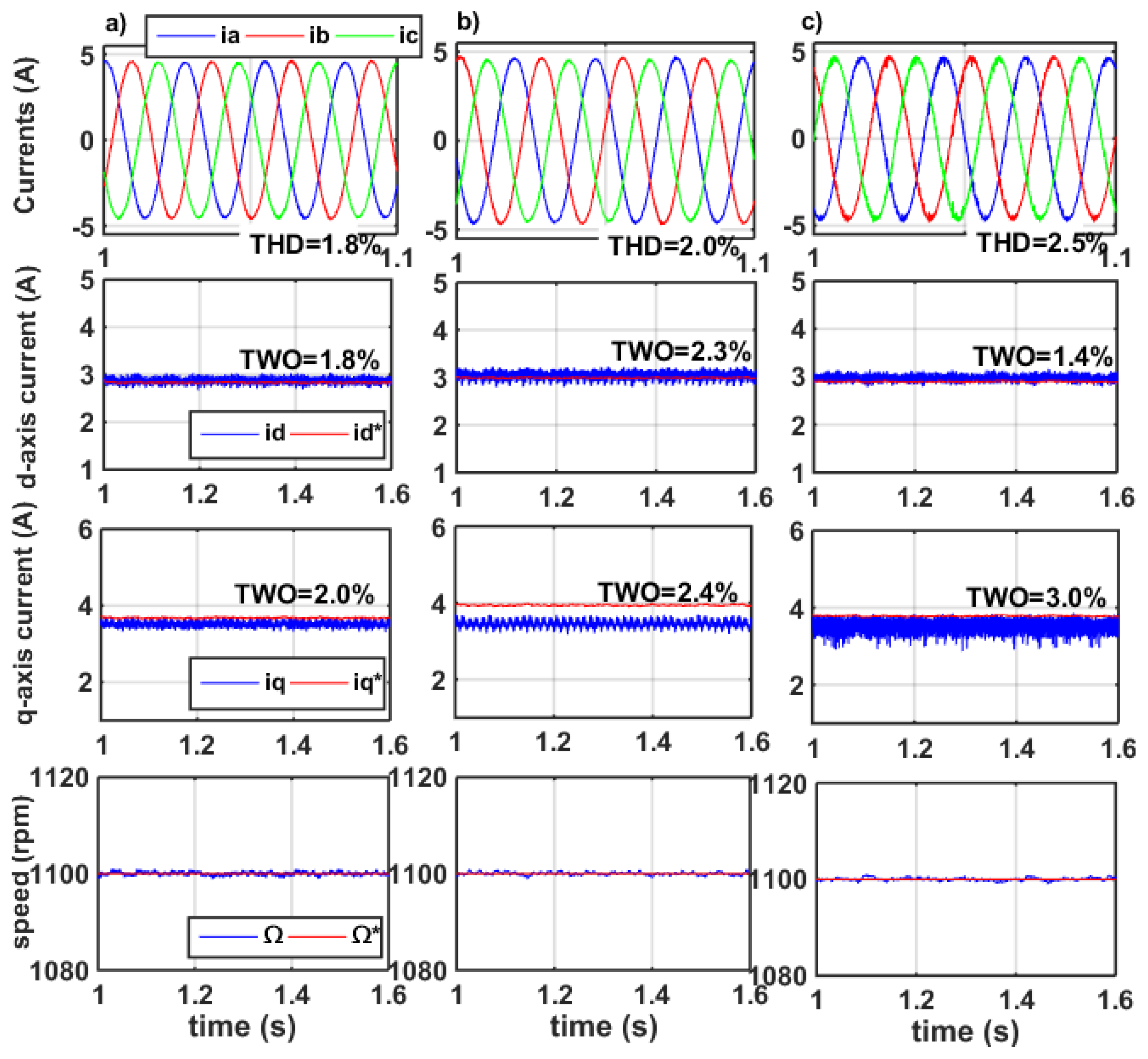
Figure 7.
Experimental results for 800 rpm and 14 Nm: (a) MBPCC with nominal parameters, (b) MBPCC under the influence of parameter variations (0.5xLd, 0.5xLq), (c) proposed GW−MFPCC.
Figure 7.
Experimental results for 800 rpm and 14 Nm: (a) MBPCC with nominal parameters, (b) MBPCC under the influence of parameter variations (0.5xLd, 0.5xLq), (c) proposed GW−MFPCC.
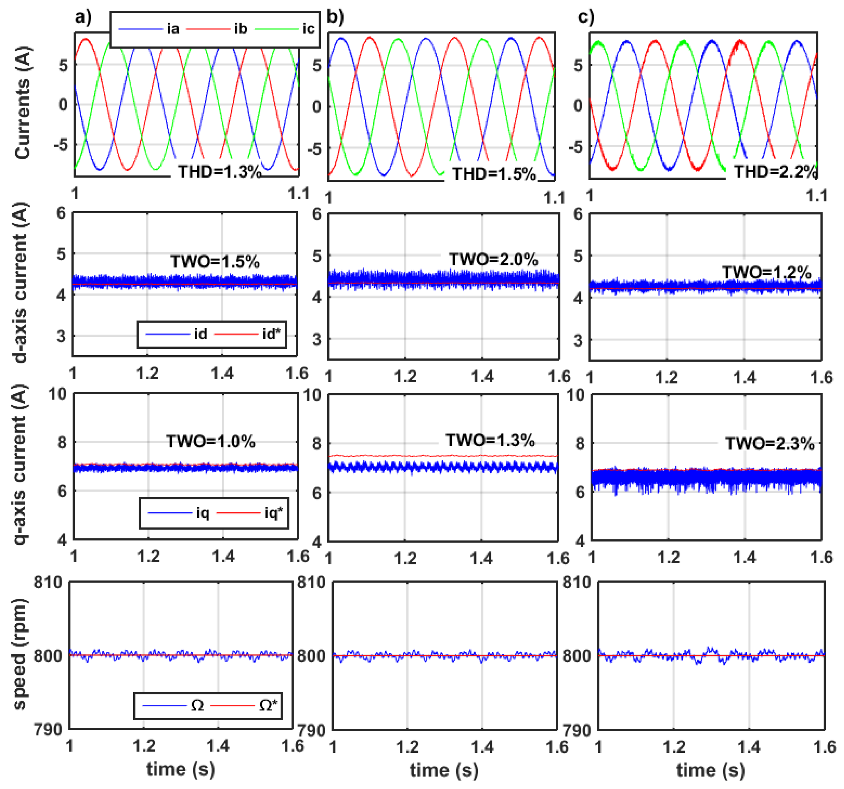
Figure 8.
Experimental results for 600 rpm and load torque variation: (a) MBPCC with nominal parameters, (b) MBPCC under the influence of parameter variations (0.3xLd, 0.3xLq), (c) proposed GW−MFPCC.
Figure 8.
Experimental results for 600 rpm and load torque variation: (a) MBPCC with nominal parameters, (b) MBPCC under the influence of parameter variations (0.3xLd, 0.3xLq), (c) proposed GW−MFPCC.
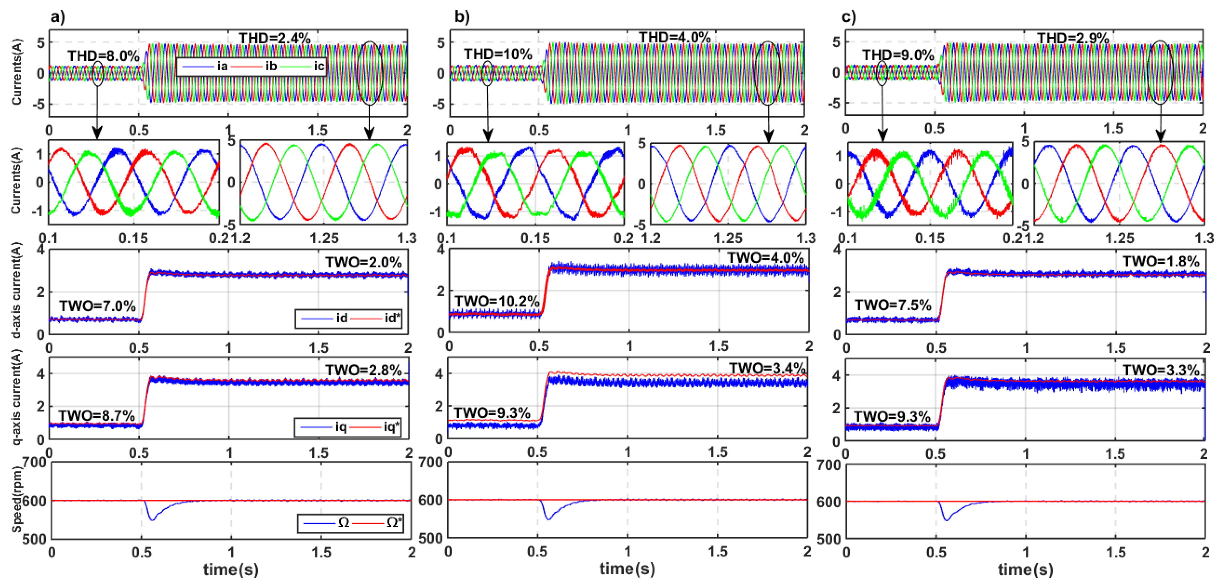
Figure 9.
Experimental results under 2 N.m and speed variation: (a) MBPCC with nominal parameters, (b) MBPCC under the influence of parameter variations (0.5xLd, 0.5xLq), (c) proposed GW−MFPCC.
Figure 9.
Experimental results under 2 N.m and speed variation: (a) MBPCC with nominal parameters, (b) MBPCC under the influence of parameter variations (0.5xLd, 0.5xLq), (c) proposed GW−MFPCC.

Table 1.
Parameters Of The Used 2.2 Kw SynRM.
| Speed N | 1500 rpm |
| Voltage V | 366 V |
| Current I | 5.7 A |
| Torque TL | 14 N.m |
| Inductances Ld/Lq | 0.24/0.057 H |
| Stator resistance Rs | 1.72 Ω |
Table 2.
Implementation complexity comparison of the MBPCC and GW−MFPCC.
| MBPCC | GW-MFPCC | |
|---|---|---|
| Motor Parameters to be tuned | Rs, Ld, Lq, and So on | Null |
| GWO Parameters to be tuned | Null | Mi, Lb, Ub, Ng |
| ExecutionTime (µs) | 25.9 | 28.5 |
Publisher’s Note: MDPI stays neutral with regard to jurisdictional claims in published maps and institutional affiliations. |
© 2022 by the authors. Licensee MDPI, Basel, Switzerland. This article is an open access article distributed under the terms and conditions of the Creative Commons Attribution (CC BY) license (https://creativecommons.org/licenses/by/4.0/).
Share and Cite
MDPI and ACS Style
Mahmoudi, A.; Jlassi, I.; Cardoso, A.J.M.; Yahia, K. Model Free Predictive Current Control Based on a Grey Wolf Optimizer for Synchronous Reluctance Motors. Electronics 2022, 11, 4166. https://doi.org/10.3390/electronics11244166
AMA Style
Mahmoudi A, Jlassi I, Cardoso AJM, Yahia K. Model Free Predictive Current Control Based on a Grey Wolf Optimizer for Synchronous Reluctance Motors. Electronics. 2022; 11(24):4166. https://doi.org/10.3390/electronics11244166
Chicago/Turabian StyleMahmoudi, Abdelkader, Imed Jlassi, Antonio J. Marques Cardoso, and Khaled Yahia. 2022. "Model Free Predictive Current Control Based on a Grey Wolf Optimizer for Synchronous Reluctance Motors" Electronics 11, no. 24: 4166. https://doi.org/10.3390/electronics11244166
Note that from the first issue of 2016, this journal uses article numbers instead of page numbers. See further details here.