Article

Torque-Pulse-Based Initial Rotor Polarity Detection for IPMSM with Low Saturation Effect

1
Institute for Electrical Drives and Actuators, Universitaet der Bundeswehr Muenchen, D-85577 Neubiberg, Germany
2
School of Automation, Nothwestern Polytechnical University, Xi’an 710129, China
3
Xiamen Tobacco Industrial Co., Ltd., Xiamen 361022, China
4
Xi’an Modern Control Technology Research Institute, Xi’an 710129, China
5
FEAAM GmbH, D-85577 Neubiberg, Germany
6
Electronics Engineering Department, University of Engineering and Technology Peshawar, Abbottabad Campus, Abbottabad 250000, Pakistan
*
Author to whom correspondence should be addressed.
Electronics 2022, 11(24), 4165; https://doi.org/10.3390/electronics11244165
Submission received: 4 October 2022 / Revised: 30 November 2022 / Accepted: 6 December 2022 / Published: 13 December 2022

Abstract

:
Referring to the sensorless control of interior permanent magnet synchronous motor (IPMSM), the initial rotor polarity is normally estimated based on the motor saturation effect. However, for certain special IPMSMs, the saturation effect is weak even at the rated point, making the saturation-based rotor polarity detection methods invalid. Therefore, this paper proposes a novel rotor polarity detection method based on torque-pulse injection. Two current pulses are imposed on the positive and negative directions of the q-axis estimated by the high-frequency injection (HFI) method, respectively; the signs of speed peaks indicate the rotor polarity. To derive the rotor polarity from the tiny speed signal, a new speed estimation method is presented. To improve the dynamic performance of speed estimation, a special current filter is adopted in the HFI method. To choose the proper width and amplitude of the current pulse under different load and inertia conditions, an automatic program is designed. The proposed method has the advantages of high accuracy, short identification time, tiny movement, and automatic operation, making it applicable to various load and inertia conditions. The effectiveness of the proposed method is validated by experiments on an IPMSM with low saturation effect.

1. Introduction

Interior permanent magnet synchronous motors (IPMSMs) are widely used in industry due to their high efficiency and high torque density. The rotor position is usually detected by the encoder, rotary transformer, etc. However, as the position sensor has the disadvantages of low reliability and high cost, a variety of sensorless control methods have been proposed for IPMSMs. At present, the sensorless control methods can be briefly classified into two main categories: the fundamental-model-based methods and the saliency-based methods. The fundamental model-based methods are available in medium and high speed ranges, while the saliency-based methods are able to track the position at standstill and low speed ranges [1,2,3,4,5,6].
Referring to the saliency-based methods, often called high frequency injection (HFI) methods, additional high-frequency voltage signals are injected into motor, allowing the rotor position to be estimated by analyzing the high-frequency current response. According to the injected signal, the HFI methods can be classified into rotating-voltage-vector injection, pulsating voltage injection, and square-wave voltage injection. However, the estimated position of these methods has an ambiguity of π rad, which means that these methods cannot identify the rotor’s magnetic polarity [3,4]. If the initial rotor polarity is incorrect, the motor will fail to start up, and may cause serious consequences.
To solve this problem, many studies have been carried out on rotor polarity detection. The most commonly used method is transient pulse injection on the d-axis [7,8,9,10,11], which is be described in Section 2. Its desired-to-undesired signal ratio (DUR) is low, as explained later. The harmonic detection method has been proposed [12,13,14] to track the rotor polarity during operation; however, it has drawbacks in that both the DUR and signal-to-noise ratio (SNR) are low. To enhance the DUR and SNR, the method of low-frequency current injection on d-axis has been proposed [15,16,17] to identify the rotor polarity, which is carried out by imposing a DC-biased or low-frequency current on the d-axis of the motor and then measuring the variation of the d-axis inductance. Due to the magnetic saturation effect, the variation of the d-axis inductance contains only the information on rotor polarity. However, all these aforementioned methods are based on the motor’s magnetic saturation effect. In practical applications, in order to achieve high overload capability the rated point of the motor is often designed to be much lower than the saturation point. In this case, the motor’s saturation effect is weak even at the rated current. In such cases, rotor polarity detection methods based on saturation effect are not reliable.
Another means of rotor polarity detection is to rotate the rotor and estimate the resulting back electromotive force (back-EMF) or acceleration; however, only few studies have been performed on this strategy. In [18,19], several voltage pulses were injected along the estimated q-axis, and the back-EMF induced by rotor movement was estimated at the same time. The sign of the back-EMF indicates the rotor polarity. However, the estimation of the back-EMF under low speed is quite complex; combining this method with a normal HFI method in position sensorless control, the program should be switched between the two methods. A simpler method was proposed in [20], in which a current ramp was imposed on the estimated q-axis, causing the sign of angular acceleration to reveal the rotor polarity. In this method, the rotor pole position and polarity are both estimated via the same HFI method. However, due to the injected current ramp signal, this method needs a longer execution time and causes larger motion of the rotor compared with the method in [18,19].
In this paper, a novel method is proposed for detecting the rotor polarity of an IPMSM with a low saturation effect. The initial rotor position is estimated by the HFI method based on rotating-voltage injection. Then, two same-current pulses are imposed on the positive and negative directions of the estimated q-axis. Meanwhile, the speed of the resulting rotor movement is estimated by the HFI method and the sign of estimated speed shows the rotor polarity. Compared with the existing torque pulse based methods, the estimated rotor position during the process of current pulse injection tracks the rotor movement, meaning that the rotor position does not need to be estimated again after polarity detection. In addition, by selecting the amplitude of the current pulse with the proposed procedure, the rotor movement can be very small even with different loads.
Additionally, due to the low dynamic performance, the speed estimation algorithm in the conventional HFI method is not suitable for the proposed rotor polarity detection. In the conventional HFI method, the negative sequence current is seriously disturbed by the fundamental current when the current pulse is imposed on the motor, which results in large distortion of the estimated speed signal [6]. This is because of the low dynamic performance of the current filter, which is utilized to extract the negative sequence current from the measured current in the conventional HFI method [3,21,22,23,24]. Therefore, an observer-based current filter [21,25] is adopted in the proposed method to improve the dynamic performance of speed estimation. Then, the disturbance of the negative sequence current caused by the fundamental current pulses is effectively suppressed, and the accuracy of momentary speed estimation is greatly improved. The proposed method is able to identify the rotor polarity accurately and rapidly in various load and inertia conditions.
The rest of this paper is organized as follows. Section 2 describes the principles of the HFI method and the conventional rotor polarity detection method based on the motor saturation effect. Then, in Section 3, our novel rotor polarity detection method based on torque-pulse injection is proposed. The procedure of this initial rotor position estimation is designed in Section 4. In Section 5, the saturation state of the IPMSM is exhibited using the finite element analysis (FEA) method. Then, experiments with different load and inertia conditions are executed to verify the effectiveness of the proposed method. At last, the proposed method is compared with a conventional rotor polarity detection method. Section 6 summarizes the paper.

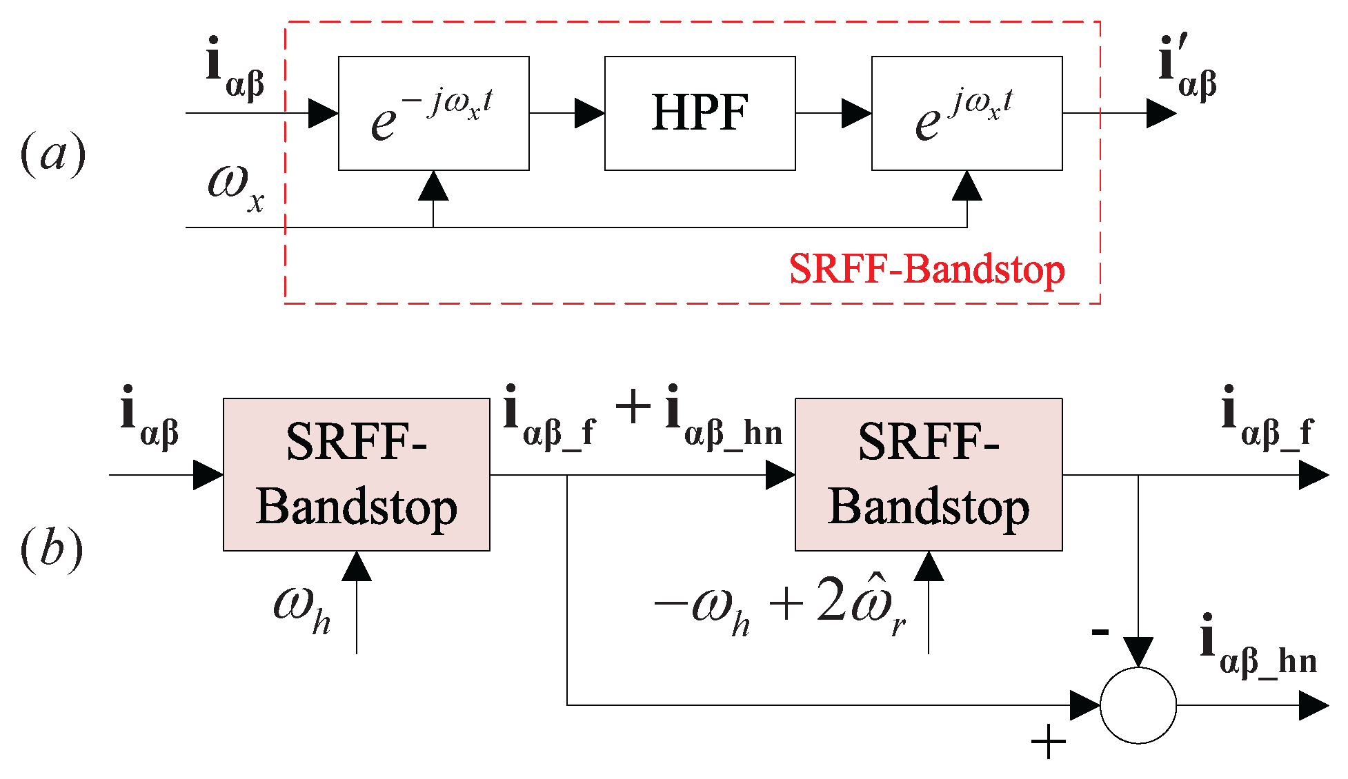
2. High Frequency Injection and Saturation-Based Rotor Polarity Detection

2.1. High Frequency Injection

In this paper, the high-frequency (HF) rotating voltage vector is injected into a stationary α β reference frame to obtain the rotor position. In the α β frame, the HF rotating voltage vector can be expressed as (1):
u α β _ h = U h · e j ω h t = U h cos ( ω h t ) sin ( ω h t )
where U h and ω h are the amplitude and angular frequency of the injected HF voltage vector. This voltage signal is superimposed on the fundamental voltage command u α β _ f ; then, the corresponding HF current respond i α β _ h can be utilized to identify the rotor position. According to [3,6,26], i α β _ h can be expressed as follows:
i α β _ h = I h p · e j ( ω h t π / 2 ) + I h n · e j ( ω h t + 2 θ r + π / 2 )
I h p = U h ω h · L L 2 Δ L 2 I h n = U h ω h · Δ L L 2 Δ L 2
Δ L = ( L q L d ) / 2 L = ( L q + L d ) / 2
where θ r is the rotor position, I h p and I h n are the amplitude of the HF positive- and negative-sequence current vectors, respectively, Δ L and L are the difference and average inductances, respectively, and L d and L q are the d- and q-axis inductances, respectively. Equation (2a) indicates that i α β _ h consists of two terms. The first term is the HF positive-sequence current vector, which rotates with frequency ω h . The second term is the HF negative-sequence current vector, which rotates in the opposite direction with frequency ω h + 2 ω r . Among them, the HF negative-sequence current contains the information of the rotor position.
Therefore, the rotor position can be identified by extracting and analyzing the HF negative-sequence current. The complete system diagram for rotor position estimation is shown in Figure 1.
The HF negative-sequence carrier current i α β _ hn and fundamental current i α β _ f are extracted from the total current response i α β using a subtraction-based current filter. Then, i α β _ hn is imported to the Luenberger-style motion observer to estimate the rotor position, and i α β _ f is fed back to the current regulator. The diagrams of subtraction-based current filter and Luenberger-style motion observer are shown in Figure 2 and Figure 3, respectively.
The filtering method based on synchronous reference frame filter (SRFF) has shown excellent performance in isolating the vectors i α β _ f and i α β _ hn when using the rotating-voltage-based HFI method [3,21,22,23,24]. Figure 2a shows the diagram of the bandstop SRFF, and its transfer function is provided in (3):
i α β i α β = s j · ω x s + ω b j · ω x
where ω x is the frequency component which needs to be eliminated, ω b is the bandwidth of the high-pass filter (HPF) inside the bandstop SRFF, meaning that the bandwidth of bandstop SRFF is ( ω x ω b , ω x + ω b ) . Figure 2b shows the structure of the subtraction-based current filter [21], which is established based on the bandstop SRFF to separate the fundamental i α β _ f and the HF negative sequence i α β _ hn from the measured total i α β .
A Luenberger-style motion observer [27] is utilized to extract the electric rotor position information from the HF negative sequence current; the diagram is shown in Figure 3. In addition, a heterodyning process is employed to calculate the position error.
According to (2a), the HF negative sequence current vector i α β _ hn can be rewritten as (4):
i α β _ hn = i α _ h n i β _ h n = I h n cos ( ω h t + 2 θ r + π 2 ) I h n sin ( ω h t + 2 θ r + π 2 )
where i α _ h n and i β _ h n are the α - and β -axis components of the HF negative sequence i α β _ hn . The heterodyning process in Figure 3 can be considered as the result of vector cross-product, as shown in (5):
ε = e j ( ω h t + 2 θ ^ r + π 2 ) × i α β _ hn = cos ( ω h t + 2 θ ^ r + π 2 ) · i α _ h n sin ( ω h t + 2 θ ^ r + π 2 ) · i β _ h n = I h n sin ( 2 ( θ r θ ^ r ) ) .
According to (5), when the difference between θ r and θ ^ r is small enough, sin ( 2 ( θ r θ ^ r ) ) is approximately equal to 2 Δ θ ^ r . However, due to the existence of coefficient 2, the results of ε are the same regardless of whether the estimated position is θ ^ r or θ ^ r + π . Therefore, the HFI method described above cannot distinguish the N and S rotor magnetic poles. Thus, an additional rotor polarity detection method should be utilized before motor start-up.

2.2. Rotor Polarity Detection Based on Saturation Effect

Normally, due to the characteristics of ferromagnetic material, the motor inductance decreases with increasing flux saturation.
Based on the motor saturation effect, the voltage pulse injection method is utilized to detect the rotor polarity after obtaining the rotor position by the HFI method. The block diagram is shown in Figure 4.
Two identical voltage pulse vectors are imposed on the of θ ^ r 0 and θ ^ r 0 + π directions, where θ ^ r 0 is the rotor position estimated by the HFI method. These two voltage pulses cause two current pulse responses. If the direction of voltage pulse vector is the same as the rotor PM flux linkage, L d decreases due to the core saturation. Otherwise, if the direction of voltage pulse vector is opposite to that of the rotor PM flux linkage, L d is approximately constant, and the corresponding current pulse vector, which has the higher amplitude, points to the real N-pole.
Note that due to the measurement error and DUR problem, the two injected voltage pulses in this method should be chosen properly to ensure that the amplitude of the induced pulses are sufficiently large that L d has noticeable changes. Otherwise, the amplitude of current pulse in the direction of N-pole may be smaller than that of the S-pole.
For certain motors, the saturation effect remains weak at the rated current. To achieve noticeable changes in L d , the amplitude of the induced current pulse should be much larger than the rated current. However, the amplitude of current pulses is confined by the limitations of the motor and inverter. Moreover, in practical sensorless control, it is difficult to determine the current amplitude at which the motor is saturated enough for the rotor polarity detection to be correct. If this determination cannot be made accurately, such rotor polarity detection methods are no longer applicable.

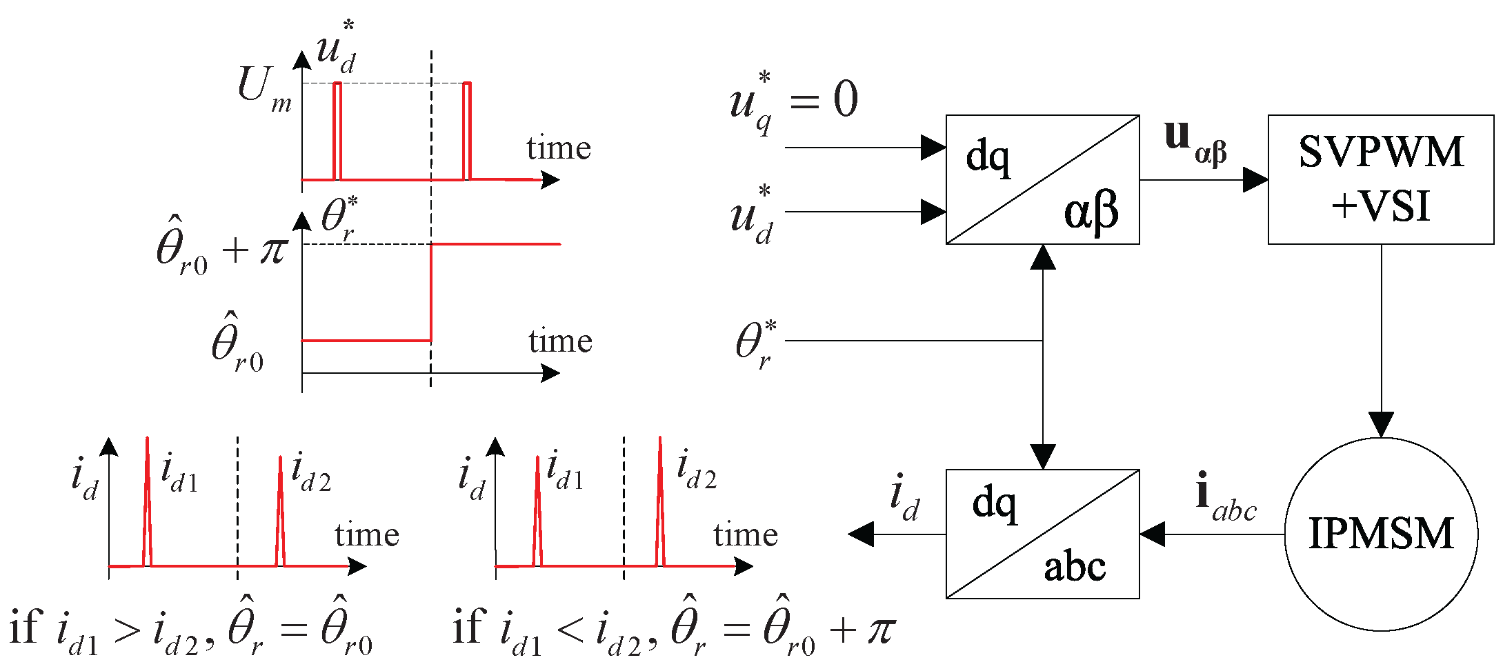
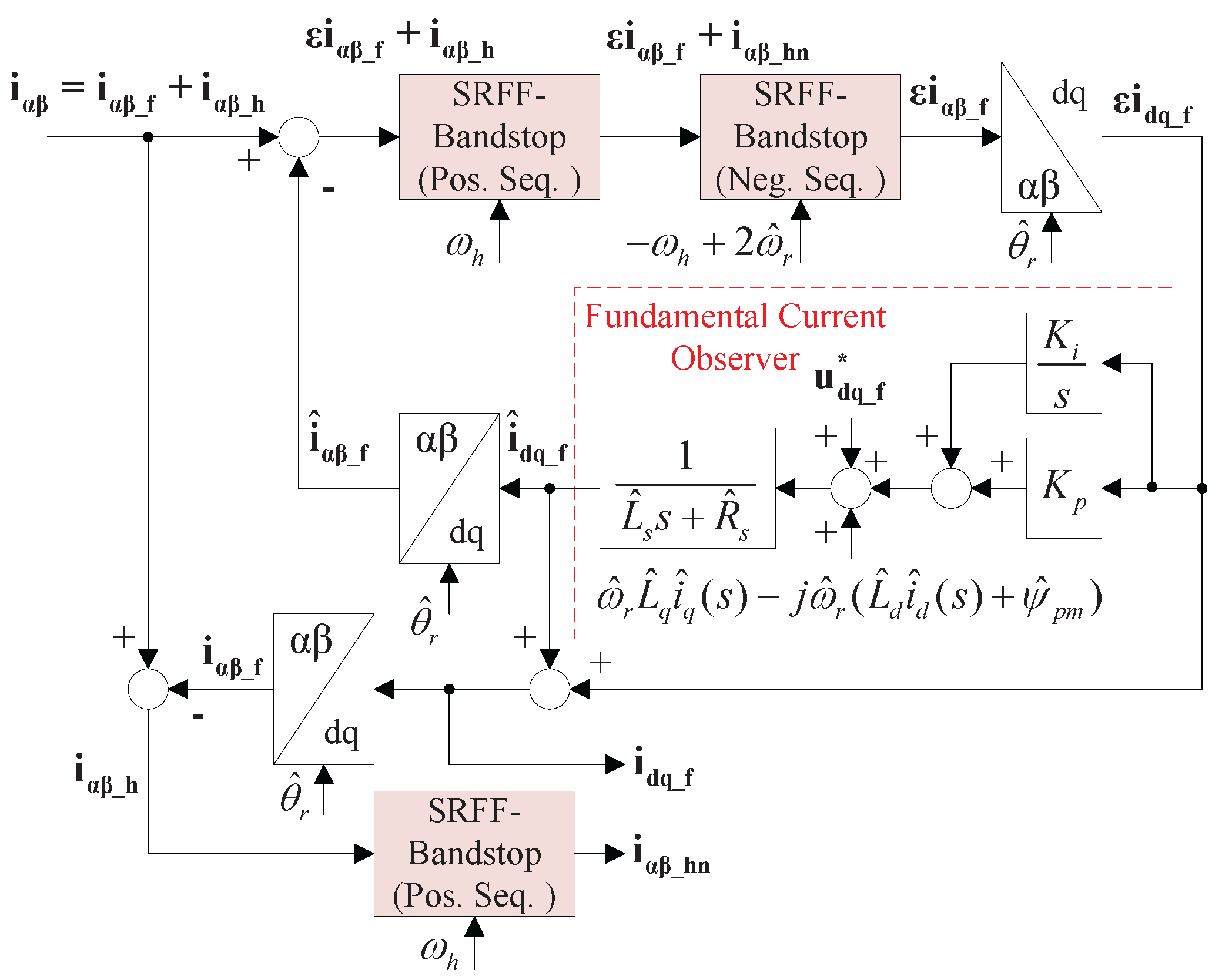
3. Rotor Polarity Detection Based on Torque-Pulse Injection

To illustrate the proposed method, the estimated d q rotary reference frame is depicted in Figure 5, where the rotor position is estimated by the HFI method. As described before, the estimated rotor position has an ambiguity of π rad. When the estimated d e s t -axis is in the direction of the real d r e a l -axis, the d q frame is as shown in Figure 5a. Otherwise, if the estimated d e s t -axis has a deviation of π , the d q frame is as shown in Figure 5b.
From Figure 5a, it can be understood that when a current pulse vector is imposed on an estimated q e s t -axis that aligns with the real q r e a l -axis, a corresponding electromagnetic torque is generated, producing a positive speed. However, if the estimated rotor polarity is opposite the real rotor’s polarity, as shown in Figure 5b, the identical current pulse vector imposed on the estimated q e s t -axis generates an opposite torque, and the speed generated by this torque is negative. Therefore, the sign of speed caused by the injected torque pulses indicates the rotor’s polarity.
In the proposed method, several testing current pulses are injected along the estimated q e s t -axis, then the generated speed is estimated by the HFI method, which is only utilized to detect rotor polarity. Therefore, the dynamic performance of speed estimation during injection of the current pulses is crucial to the proposed method.
The HF negative-sequence current is the basis for rotor position estimation in the HFI method. However, the HF negative-sequence current is distorted by the harmonic components inside the fundamental pulse current when using the conventional current filter to separate the fundamental current and HF negative-sequence current during current pulse injection, resulting in huge errors in the estimated position and speed. In order to improve the dynamic performance, a current-observer-based current filter [21,25] is adopted here to replace the conventional subtraction-based current filter in the HFI method. Its simplified diagram is shown in Figure 6.
In Figure 6, a fundamental current observer is embedded in this filter. After the observer predicts the fundamental current i s _ f , the predicted current i s _ f is subtracted from the actual total current i s _ f to obtain the HF current i s _ h . In this way, the distortion of the HF negative-sequence current i s _ hn caused by the fundamental current pulse can be suppressed, meaning that the transient estimated position and speed error can be minimized as well.
The total diagram of the current-observer-based current filter is shown in Figure 7. Because the IPMSM model is based on the d q frame, the coordinate transformation is added to the current filter algorithm.
The diagram of torque-pulse based rotor polarity detection with the current-observer-based current filter is shown in Figure 8. The sign of the estimated speed can used to indicate the rotor’s polarity.
As shown in Figure 8, two current pulses are imposed on the positive and negative directions of the q-axis; the angle inputs of park transformation are set as θ ^ r 0 and θ ^ r 0 + π , respectively, where θ ^ r 0 is the initial angle calculated by the HFI method at standstill. Then, the rotor polarity is obtained by comparison to the estimated speed.
Although the disturbance in speed estimation caused by current pulses is effectively suppressed, disturbance ripples may continue to exist in the speed signal. As illustrated by Figure 8, when one current pulse is imposed, both positive and negative ripples are generated in the estimated speed signal on account of the disturbance noises. In order to improve the accuracy and robustness of rotor polarity detection, the rotor polarity should be detected by comparing the positive and negative peaks induced by the two opposite current pulses.
In Figure 8, ω ^ 1 p and ω ^ 1 n are the positive and negative speed peaks generated by the first current pulse, while ω ^ 2 p and ω ^ 2 n are the positive and negative speed peaks generated by the second current pulse. If both ω ^ 1 p and ω ^ 1 n are respectively larger than ω ^ 2 p and ω ^ 2 n , the actual rotor position is the angle of only the first current pulse, namely, θ ^ r 0 . Otherwise, if ω ^ 1 p and ω ^ 1 n are respectively smaller than ω ^ 2 p and ω ^ 2 n , the actual rotor position is the angle of only the second current pulse, namely, θ ^ r 0 + π . Note that, due to speed estimation error, if there are speed ripples in other situations, such as ( ω ^ 1 p > ω ^ 2 p and ω ^ 1 n < ω ^ 2 n ) or ( ω ^ 1 p < ω ^ 2 p and ω ^ 1 n > ω ^ 2 n ) , the detection results are invalid and rotor polarity detection should be carried out again.
Moreover, in order to reduce interference and improve the accuracy of rotor polarity detection, the estimated speed signals are processed by a low-pass filter (LPF) before being utilized to detect rotor polarity. The selection of cut-off frequency is not strict. When the cut-off frequency is lower, the interference suppression is better; however, the output speed signal takes more time to converge. In addition, because the HFI method is only valid at low speed ranges, the cut-off frequency should be lower than the frequency corresponding to the speed at 100 rpm. In this paper, the cut-off frequency is chosen as 10 Hz.
In addition, the magnitude and width of the current pulses should be chosen carefully to ensure that the generated motion of the rotor is small enough while being detectable with the HFI method. The procedure of initial rotor position estimation, including finding the appropriate injected current pulse, is described in the following section.

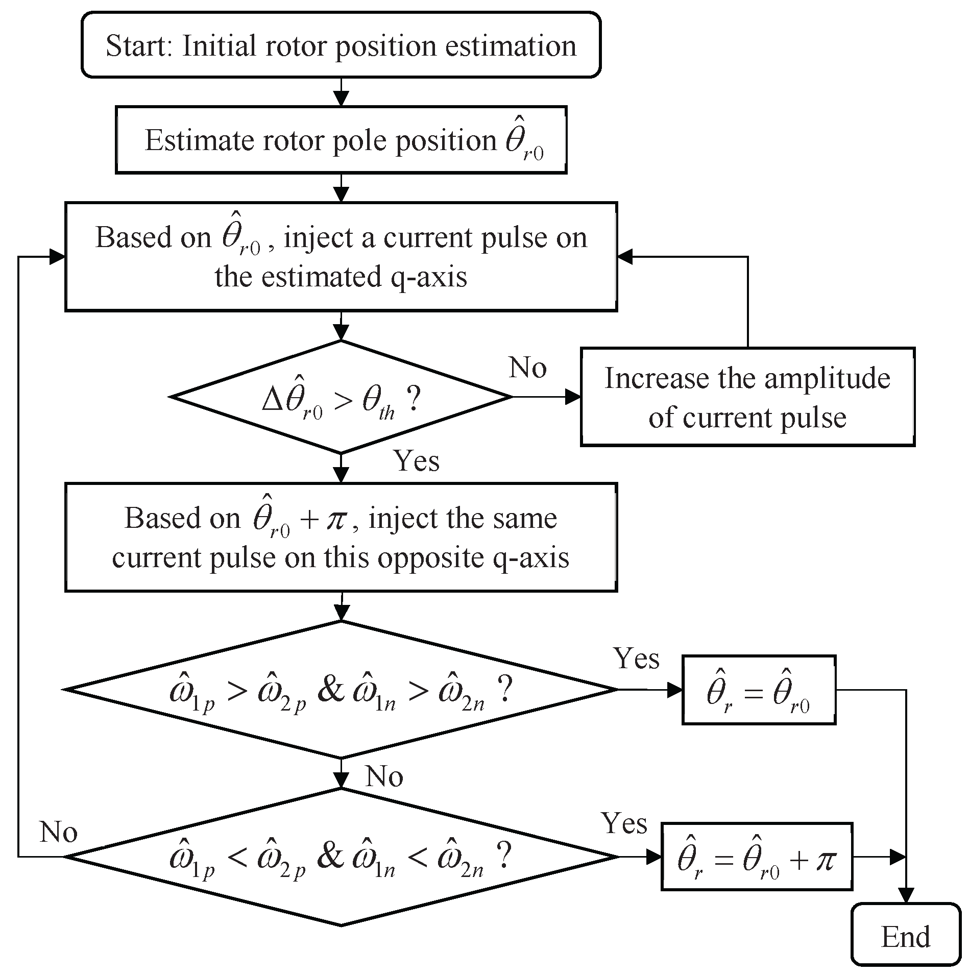
4. Procedure of Initial Rotor Position Estimation

In many practical applications, the inertia and static friction of the load system are unknown. Therefore, a set of testing current pulses are injected into the estimated q-axis before the rotor polarity detection. The width or amplitude of these testing current pulses increases gradually until a suitably small movement of the rotor is detected by the HFI method. This ensures that the width and amplitude of the pulse are appropriate and can be utilized for rotor polarity detection.
The flowchart of the procedure is shown in Figure 9, and described in detail below.
Step 1: Estimate the rotor pole position. In this step, the current commands i q * and i d * are both set as 0. The initial rotor position θ ^ r 0 can be estimated by the HFI sensorless method at standstill.
Step 2: Based on the estimated position θ ^ r 0 , a positive current pulse is imposed on the estimated q-axis, which causes a small motion of the rotor. The amplitude and width of the current pulse are initially chosen as small values. Record the rotor movement Δ θ ^ r 0 and speed variation estimated by the HFI method and proceed to step 3.
Step 3: Choose a proper amplitude and width of current pulse. If the estimated motion angle Δ θ ^ r 0 is over a small threshold θ t h , the amplitude and width values of the current pulse are appropriate; in this case, keep these values and continue to step 4. Otherwise, if the motion angle is too small, increase the amplitude of current pulse while retaining the width constant, then return to step 2.
Step 4: By adding the deviation π to the estimated position θ ^ r 0 , the newly formed q-axis is opposite to the q-axis in step 2. Then, the same current pulse is imposed on this q-axis, causing a rotor motion opposite to the rotor position in step 2. Record the speed variation estimated by the HFI method.
Step 5: The rotor polarity can now be obtained by comparing the speeds estimated in steps 2 and 4. As shown in Figure 8, the positive and negative speed peak values generated by the first current pulse in step 2 are denoted as ω ^ 1 p and ω ^ 1 n , while the positive and negative speed peak values generated by the second current pulse in step 4 are denoted as ω ^ 2 p and ω ^ 2 n .
If ω ^ 1 p > ω ^ 2 p and ω ^ 1 n > ω ^ 2 n , the rotor position is θ ^ r 0 .
If ω ^ 1 p < ω ^ 2 p and ω ^ 1 n < ω ^ 2 n , the rotor position is θ ^ r 0 + π .
Otherwise, if ( ω ^ 1 p > ω ^ 2 p and ω ^ 1 n < ω ^ 2 n ) or ( ω ^ 1 p < ω ^ 2 p and ω ^ 1 n > ω ^ 2 n ) , the for rotor polarity detection test result is invalid. In this case, return to step 2 and repeat the test.

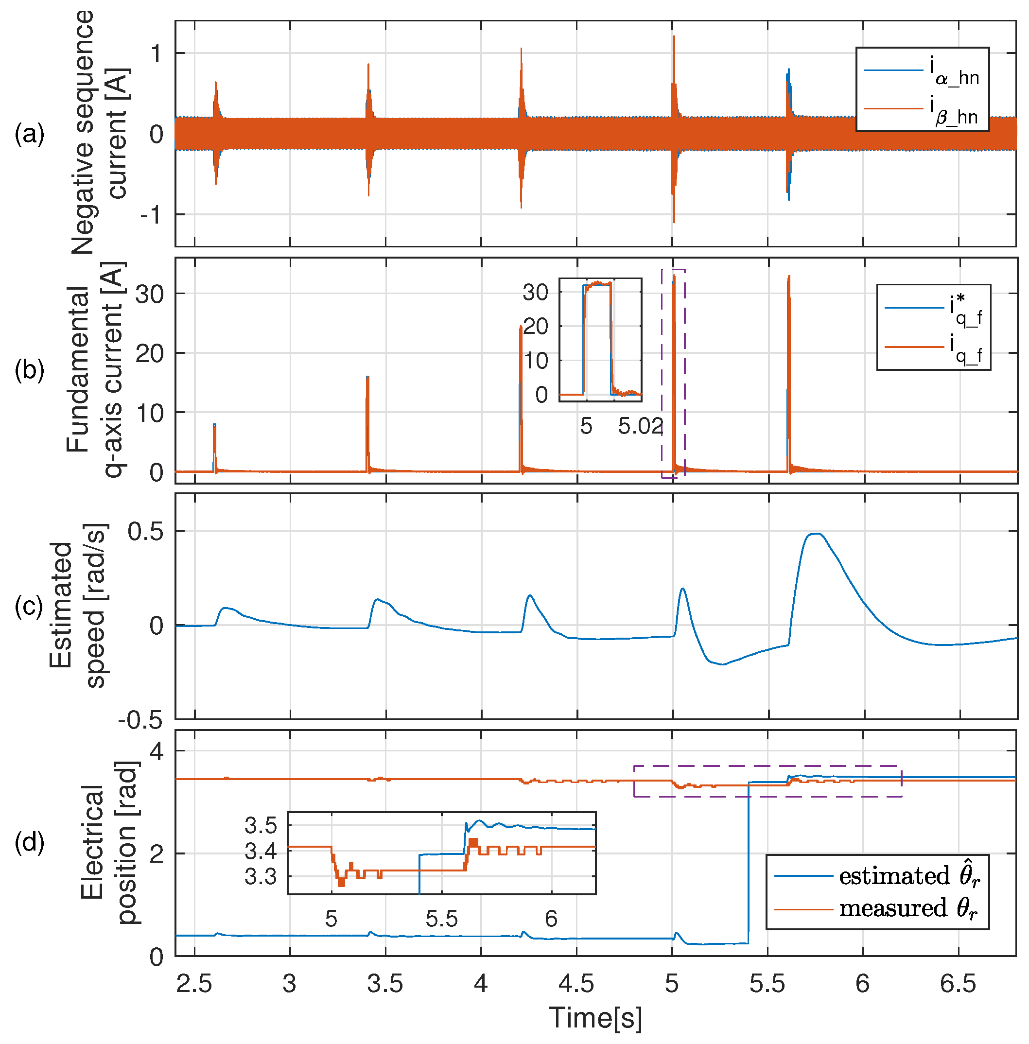
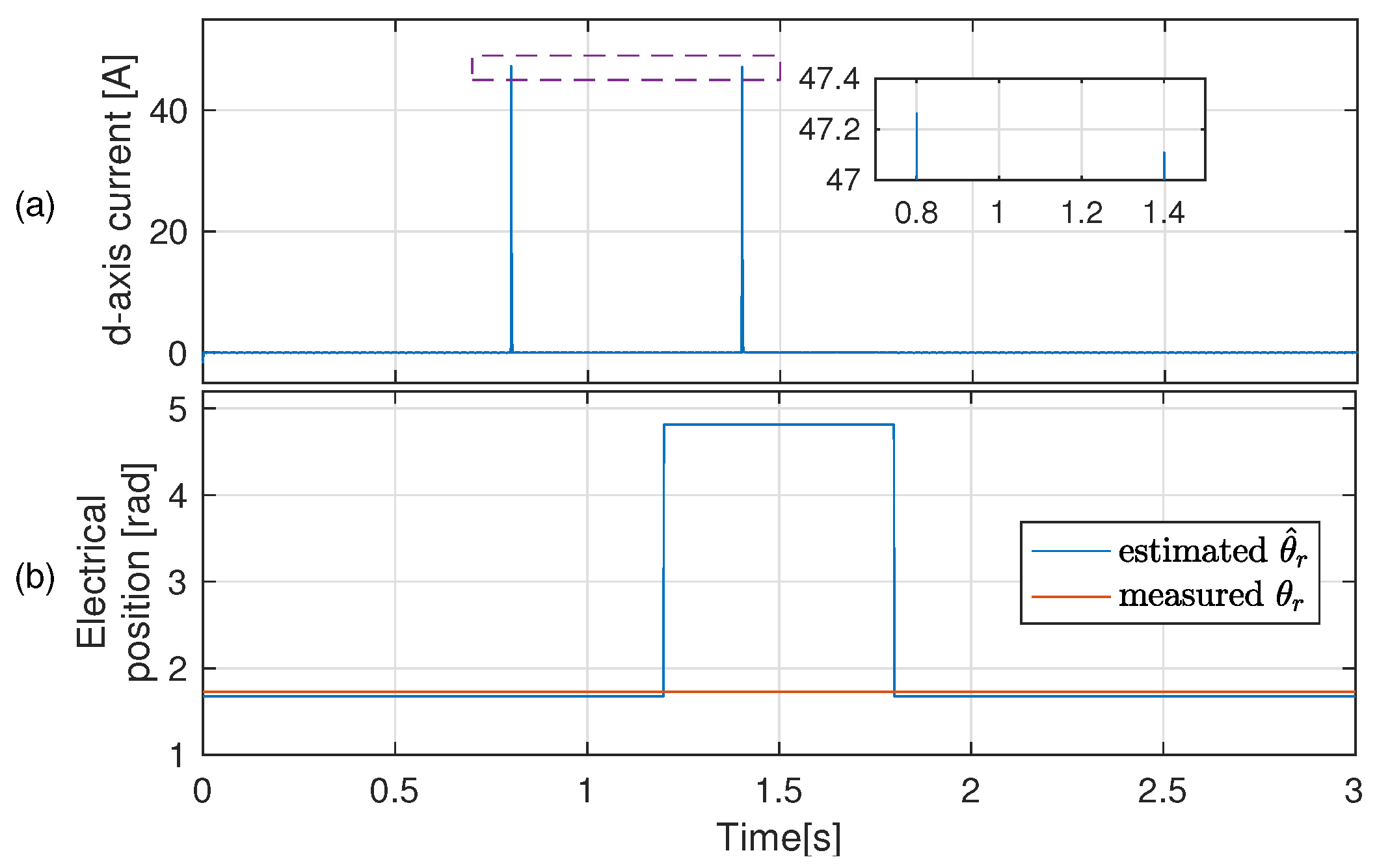
5. Experimental Verification

5.1. Saturation Effect of the IPMSM Studied in this Paper

In comparison with the normal IPMSM, the saturation effect of the IPMSM studied in this paper is much weaker. Its structure is described in detail in [28] and its parameters are listed in Table 1.
In order to analyze the saturation effect, the inductance maps of the d q -axis as calculated by the finite element analysis (FEA) method are depicted in Figure 10. The FEA results show that L d and L q are nearly constant at different d- and q-axis currents.
In conventional saturation-based rotor polarity detection, the accuracy is related to the saturation effect of L d . When the saturation effect is stronger and the variation of L d is larger at different i d , then the accuracy is higher. However, for the IPMSM studied in this paper, as shown in the Figure 10a, the variation of L d is small even when i d is at the rated current. To describe the saturation effect more clearly, we simulated the flux density and relative permeability at ( i d , i q ) = ( 60 , 0 ) A by FEA, as shown in Figure 11a,b.
When the relative permeability is closer to one, the magnetic core is more saturated. From Figure 11b, it can be seen that the saturated area, indicated by the blue area, is very small, whereas most of the area in the motor core is unsaturated. From this, we can conclude that the saturation characteristic of the IPMSM studied in this paper is rather weak. Therefore, when using the conventional method based on the saturation effect, the detection of rotor polarity is not accurate.

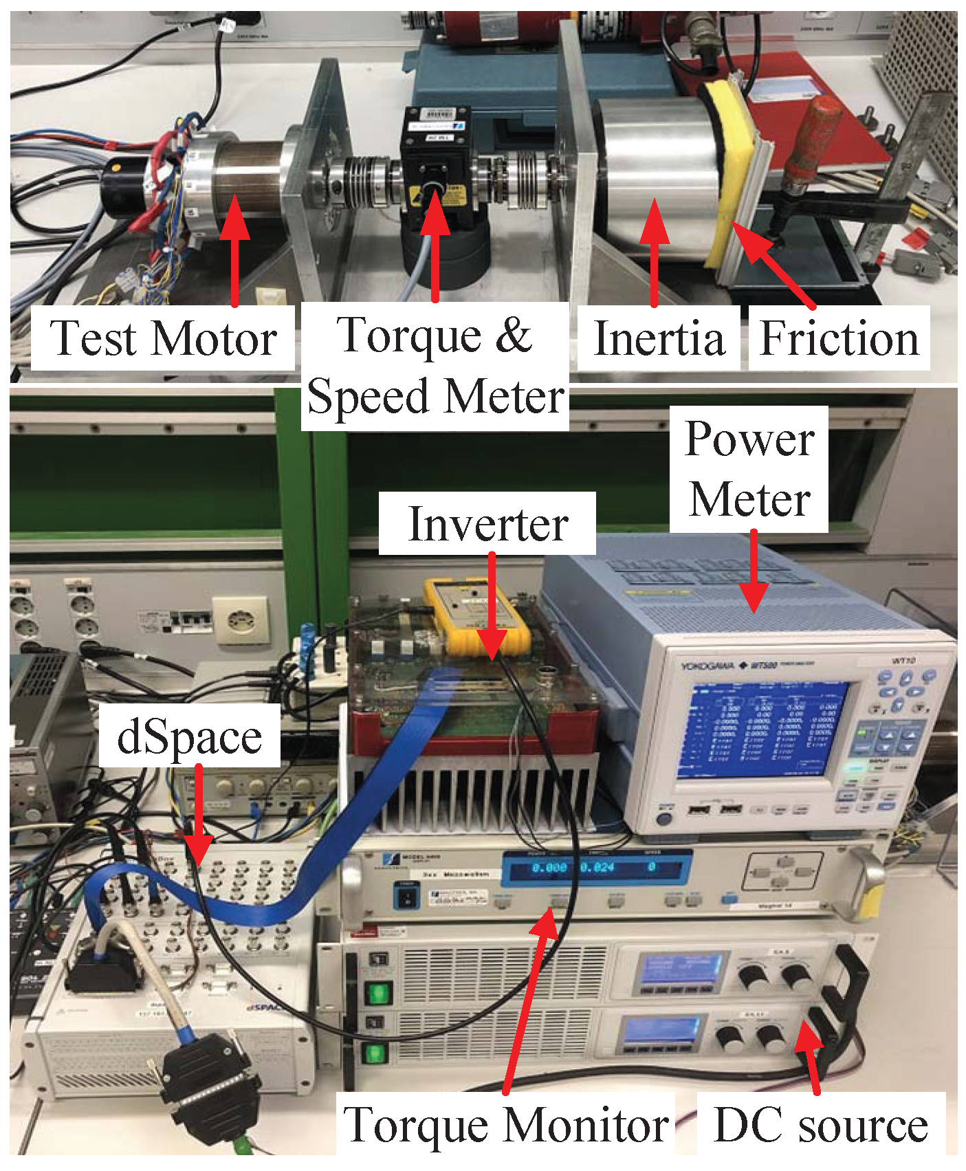
5.2. Test Bench Introduction

All the experiments in this paper are carried out with the test bench shown in Figure 12. The test motor studied in this paper is an IPMSM, introduced above in detail. The dSpace MicroLabBox is adopted as the controller, and the inverter is based on the MOSFET IPB180N10S4-02. To confirm the accuracy of rotor position and polarity estimation, an absolute encoder (ROC410) with 10-bit resolution is installed in the motor. To test the proposed rotor polarity detection method under different load and inertia conditions, a mass block, with a moment of inertia of 6 g · m2 is mounted on the load side and an additional mechanism is attached to the mass block, providing static friction of about 0.52 N · m. In all the following experiments, the shaft of the test motor is free to move in order for vibrations to be generated by the torque pulses.

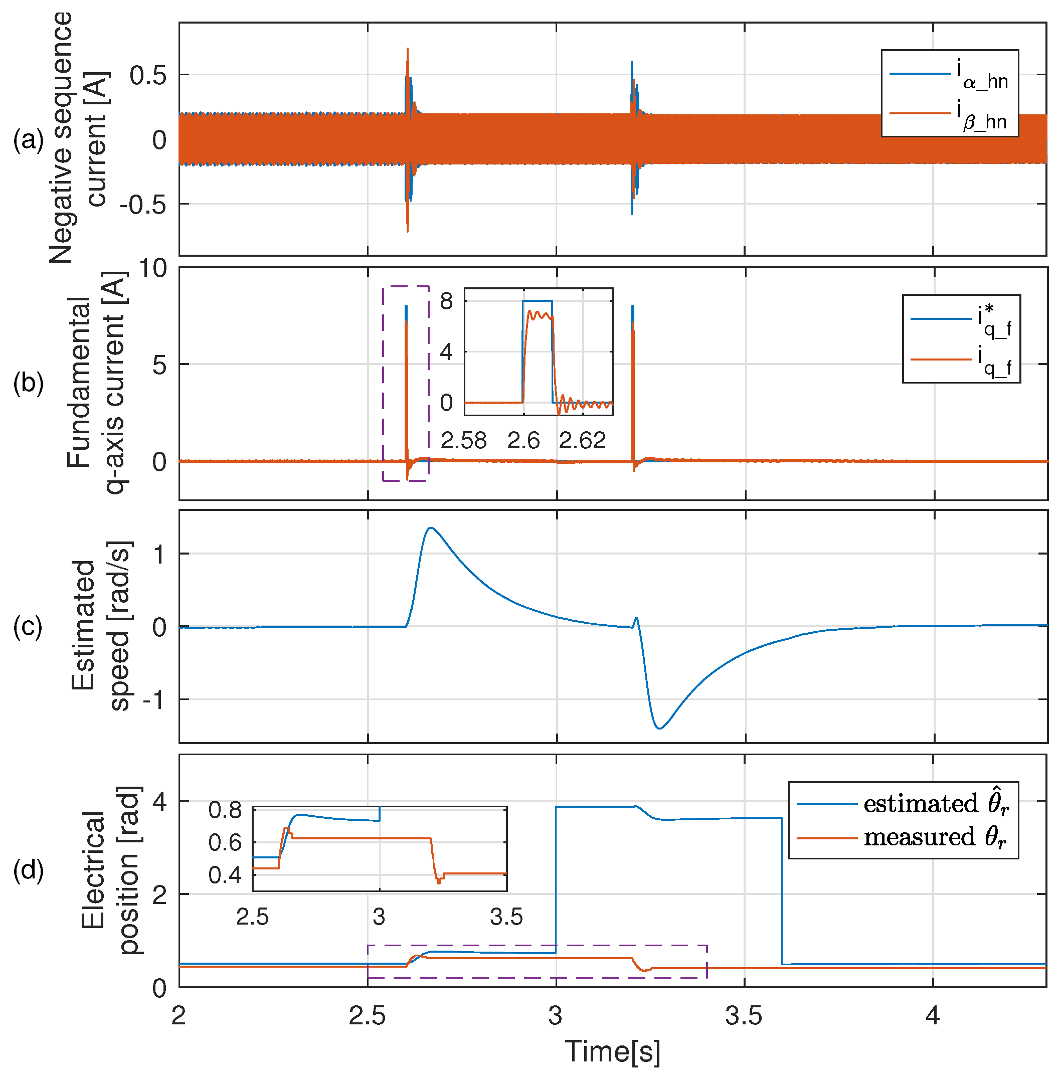
5.3. Initial Rotor Position Estimation with No Load

In the following sections, the proposed rotor polarity detection method is verified by three tests implemented with no load, an inertia load, and an inertia–friction load. This section shows the testing result with no load.
To improve the dynamic performance of speed estimation, a current-observer-based current filter is adopted to replace the conventional subtraction-based current filter in HFI method. To verify the effectiveness of the current-observer-based current filter, the rotor polarities are detected by the HFI method using current-observer-based current filter and by the HFI method using subtraction-based current filter, respectively.

5.3.1. The Proposed Method with Current-Observer-Based Current Filter

The experimental results of initial rotor position estimation using the proposed method with no load are shown in Figure 13.
The amplitude and width of the current pulse imposed on the estimated q-axis are initially set as small values (8 A and 0.01 s), where the amplitude is 0.2 times of the rated current. As the rotor movement caused by the current pulse is bigger than the threshold angle of 0.1 rad, this amplitude value for the current pulse is sufficient. From Figure 13d, at the beginning, the estimated rotor angle is 0.735 rad, which means that the real position can be either 0.735 rad or ( 0.735+ π ) rad. The first current pulse is imposed on the q-axis based on the initial estimated angle, then the second current pulse with the same amplitude and width is imposed on the opposite q-axis, where the estimated angle is ( 0.735+ π ) rad.
According to step 5 in the rotor polarity estimation procedure described in Section 4, the rotor polarity is determined by comparing the speed peaks caused by the two current pulses. From Figure 13c, it is apparent that the first current pulse generates the largest positive speed peak and the second pulse generates the smallest negative speed peak. Therefore, the estimated position of the first current pulse is determined to be the final estimated position.

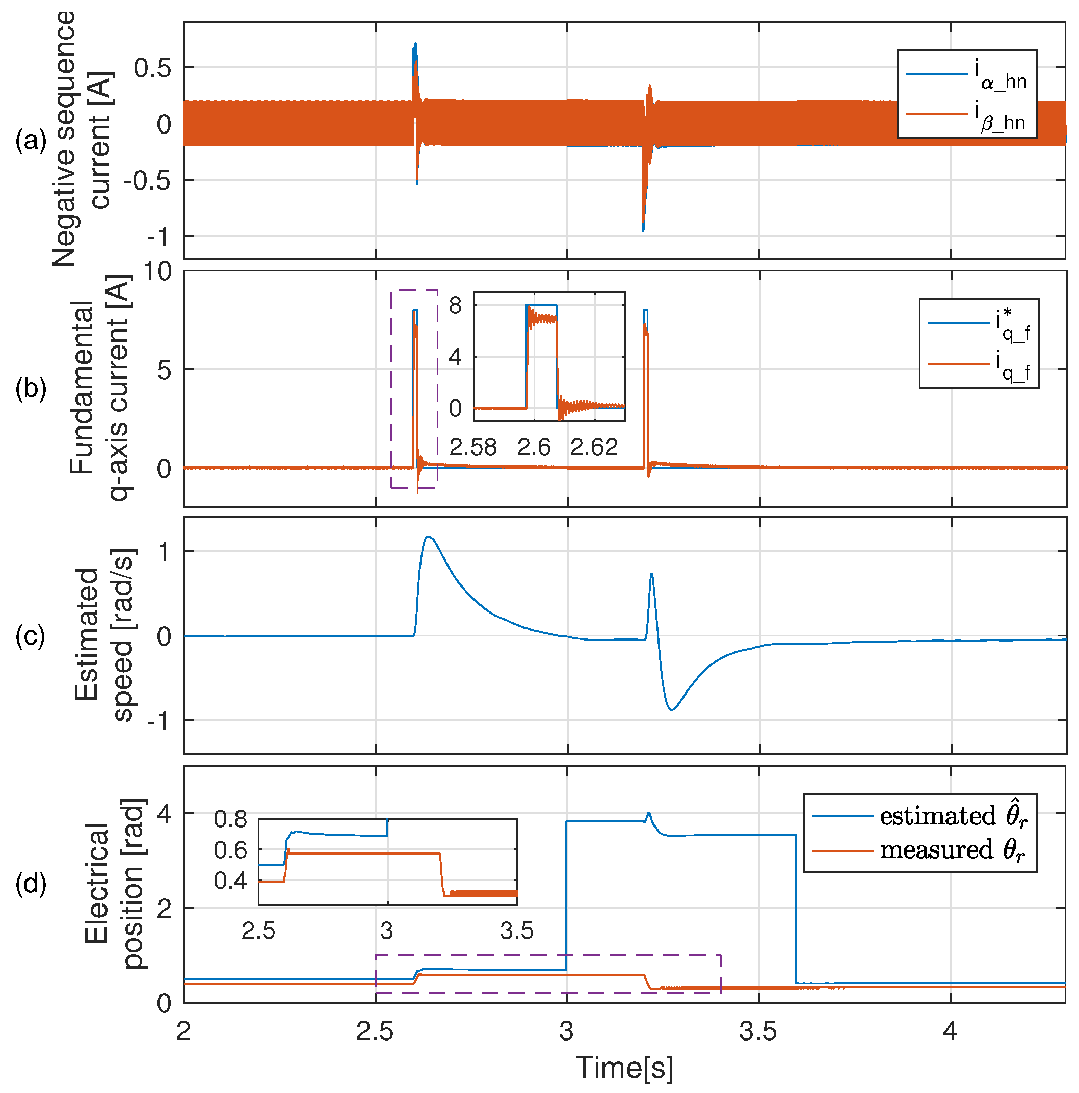
5.3.2. Comparison with Method Using Conventional Subtraction-Based Current Filter

For comparison, the similar procedure of the proposed rotor polarity detection method is implemented here, with the current-observer-based current filter replaced by the conventional subtraction-based current filter used in the HFI method. The experimental results are shown in Figure 14. This experiment is again implemented with no load, and the actual rotor position is similar to that in the previous experiment.
Comparing Figure 13 and Figure 14, the same current pulse commands are imposed on the estimated q-axis. However, when using the conventional subtraction-based current filter, the extracted negative sequence current i α _ h n , i β _ h n and fundamental current i q _ f contain more noise, as shown in Figure 14a,b. This results in a large disturbance ripple in the estimated speed at the second current pulse of about 0.8 rad/s, as shown in Figure 14c. However, when using the proposed current-observer-based current filter, the disturbance ripple is significantly reduced to about 0.1 rad/s, as shown in Figure 13c. Therefore, it is meaningful to use the current-observer-based current filter with the HFI method to improve the dynamic performance of speed estimation.

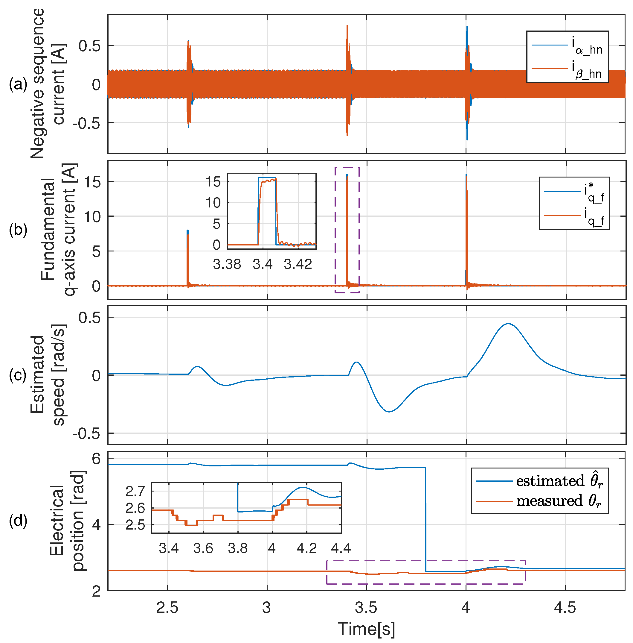
5.4. Initial Rotor Position Estimation with Inertia Load

In this experiment, a mass block with a moment of inertia of 6 g · m2 is connected to the IPMSM; the experimental results of initial rotor position estimation are shown in Figure 15.
According to the procedure for rotor polarity detection described above, several testing current pulses with increased amplitude are imposed on the estimated q-axis to determine a proper amplitude. As shown in Figure 13d, the rotor movement caused by the second current pulse is larger than 0.1 rad, meaning that the amplitude 16 A of this current pulse is chosen for rotor polarity detection. The rotor position is initially estimated as 5.809 rad. Then, a third current pulse with amplitude 16 A is imposed opposite the initially estimated q-axis, where the estimated position is ( 5.809 π ) rad.
Figure 13c compares the speed peaks generated by the second and third current pulses; the third pulse generates a larger positive speed peak and smaller negative peak. Therefore, according to the procedure of rotor polarity detection described above, the estimated angle of the third pulse is finally determined to be the actual estimated position.

5.5. Initial Rotor Position Estimation with Inertia-Friction Load

Lastly, a mechanism is added to provide the friction of 0.52 N · m; then, an experiment with both an inertia and a friction load is implemented, as shown in Figure 16.
According to the procedure for estimating rotor polarity, because the friction load is added to the inertia load, a sequence of testing current pulses with gradually increasing amplitude are imposed on the estimated q-axis until the rotor movement is larger than 0.1 rad. As shown in Figure 16b, at this time the amplitude of current pulse is 32 A. From Figure 16d, the initially estimated rotor position is 0.395 rad, which has a deviation of π from the measured angle. After using the proposed rotor polarity detection method, the deviation is eliminated and the final estimated rotor position correctly matches the measured angle.

5.6. Comparison with the Saturation-Based Method

To validate the effectiveness and robustness of our approach, the proposed torque-pulse-based rotor polarity detection method is compared with the conventional saturation-based method described in Section 2 in the no-load condition. Both the saturation-based method and torque-pulse-based method are tested ten times at different rotor positions, with the results summarized in Table 2. According to Table 2, only six tests of rotor polarity detection method based on the saturation effect are correct, whereas all ten tests are correct when using our proposed torque pulse-based method.
One of the ten tests of the saturation-based method is plotted in Figure 17, and one of the ten tests of the torque pulse-based method is plotted in Figure 18.
Referring to the conventional saturation-based method, the rotor’s polarity is determined by comparing the magnitude of current pulses on the d-axis, as shown in Figure 17a. The estimated position corresponding to the larger current pulse is determined to be the final estimated position, as shown in Figure 17b. Although the final estimated rotor position contains the correct rotor polarity, the magnitude of the difference between the two current pulses is too small in comparison with the magnitude of the current pulse itself. The ratio of the magnitude of the difference to the magnitude of the current pulse itself is defined as the desired-to-undesired signal ratio (DUR) in [20]. From Figure 17a, the DUR value in this test is very low, because the saturation effect of the motor studied in this paper is quite weak even when the d-axis current is 47 A, which is around 1.2 times the rated current. In this case, the accuracy of rotor polarity detection can be severely affected by electromagnetic interference. Therefore, of the ten tests using the conventional saturation-based method, only six are correct.
However, for the test using the proposed torque pulse-based method, the rotor polarity is determined by the sign of speed peaks, as shown in Figure 18. Then, the DUR can be defined as the ratio of difference between the magnitude of the speed peaks and the magnitude of the speed peaks themselves. From Figure 18a, the DUR vaule of the proposed method is quite large. Therefore, the accuracy of rotor polarity detection is high, and all ten tests using the proposed method are correct.
Compared with the saturation-based method, the proposed method is more feasible when the motor saturation effect is weak. When using the proposed method, the detection result has higher DUR and SNR values, and is more robust against electronic noise.

6. Conclusions

Because the conventional saturation-based method is inaccurate for IPMSMs with low saturation effects, a novel torque pulse-based rotor polarity detection method is proposed in this paper. The HFI method based on rotating-voltage-vector injection is utilized to estimate the rotor pole position; then, two identical current pulse commands are imposed on the estimated q-axis and its opposite direction to generate torque pulses and small rotor movements. The rotor polarity can be detected by comparing the positive and negative peaks of the speed signals estimated by the HFI method. To improve the dynamic performance of speed estimation, a current-observer-based current filter is adopted in the HFI method instead of the conventional subtraction-based current filter.
Our experimental results validate the effectiveness of the proposed method. Under different load conditions, the initial rotor polarity can always be estimated correctly. At the same time, the motion of the rotor is tiny when selecting the magnitude of current pulses with the proposed procedure. Compared with the conventional saturation-based method, the proposed method has higher accuracy and robustness when the motor saturation effect is weak. This method is suitable for certain actual applications in which only small motion of rotor is allowed before motor startup, such as high-ratio gears, pumps, and fans. In the future, we intend to test the proposed method in the IPMSM of a vehicle steering system in order to verify the effectiveness of our method in practical applications.

Author Contributions

Conceptualization, W.Y. and Y.W.; methodology, W.Y.; software, H.G.; validation, X.S., S.R. and H.Z.; formal analysis, W.Y.; investigation, Y.W.; resources, H.G. and G.D.; data curation, G.D.; writing—original draft preparation, W.Y.; writing—review and editing, Y.W.; visualization, H.G.; supervision, D.G.; project administration, S.R. and H.Z.; funding acquisition, Y.W. and D.G. All authors have read and agreed to the published version of the manuscript.

Funding

This research was funded by the Natural Science Basic Research Program of Shaanxi (grant number 2021JQ-106); Aero Science Foundation of China (grant number 20200007053003), and National Natural Science Foundation of China (grant number 52107057).

Data Availability Statement

Not applicable.

Conflicts of Interest

The authors declare no conflict of interest.

Nomenclature

u α β _ f Fundamental voltage command vector in α β axis
u α β _ h Injected high-frequency rotating voltage vector in α β axis
i α β Measured total current vector in α β axis
i α β _ f Fundamental current vector in α β axis
i α β _ h High-frequency current vector in α β axis
i α β _ hn High-frequency negative-sequence current vector in α β axis
i dq _ f Fundamental current vector in d q axis
ω r Real electrical rotor speed
θ r Real electrical rotor position
ω ^ r Estimated electrical rotor speed
θ ^ r Estimated electrical rotor position
L d , L q Stator inductance (d and q axes, respectively)
i d * , i q * Fundamental current command (d and q axes, respectively)
θ r * Electrical rotor position command

References

  1. Wang, G.; Valla, M.; Solsona, J. Position Sensorless Permanent Magnet Synchronous Machine Drives—A Review. IEEE Trans. Ind. Electron. 2020, 67, 5830–5842. [Google Scholar] [CrossRef]
  2. Xiao, D.; Nalakath, S.; Filho, S.R.; Fang, G.; Dong, A.; Sun, Y.; Wiseman, J.; Emadi, A. Universal Full-Speed Sensorless Control Scheme for Interior Permanent Magnet Synchronous Motors. IEEE Trans. Power Electron. 2021, 36, 4723–4737. [Google Scholar] [CrossRef]
  3. Raca, D.; Garcia, P.; Reigosa, D.D.; Briz, F.; Lorenz, R.D. Carrier-signal selection for sensorless control of pm synchronous machines at zero and very low speeds. IEEE Trans. Ind. Appl. 2010, 46, 167–178. [Google Scholar] [CrossRef]
  4. Benjak, O.; Gerling, D. Review of position estimation methods for pmsm drives without a position sensor, part iii: Methods based on saliency and signal injection. In Proceedings of the 2010 International Conference on Electrical Machines and Systems (ICEMS), Incheon, Republic of Korea, 10–13 October 2010; pp. 873–878. [Google Scholar]
  5. Bojoi, R.; Pastorelli, M.; Bottomley, J.; Giangrande, P.; Gerada, C. Sensorless control of pm motor drives—A technology status review. In Proceedings of the 2013 IEEE Workshop on Electrical Machines Design, Control and Diagnosis (WEMDCD), Paris, France, 11–12 March 2013; pp. 168–182. [Google Scholar]
  6. Zhu, Z.Q.; Gong, L.M. Investigation of effectiveness of sensorless operation in carrier-signal-injection-based sensorless-control methods. IEEE Trans. Ind. Electron. 2011, 58, 3431–3439. [Google Scholar] [CrossRef]
  7. Holtz, J. Acquisition of position error and magnet polarity for sensorless control of pm synchronous machines. IEEE Trans. Ind. Appl. 2008, 44, 1172–1180. [Google Scholar] [CrossRef]
  8. Wang, G.; Qu, L.; Zhan, H.; Xu, J.; Ding, L.; Zhang, G.; Xu, D. Self-commissioning of permanent magnet synchronous machine drives at standstill considering inverter nonlinearities. IEEE Trans. Power Electron. 2014, 29, 6615–6627. [Google Scholar] [CrossRef]
  9. Wu, X.; Feng, Y.; Liu, X.; Huang, S.; Yuan, X.; Gao, J.; Zheng, J. Initial rotor position detection for sensorless interior pmsm with square-wave voltage injection. IEEE Trans. Magn. 2017, 53, 1–4. [Google Scholar] [CrossRef]
  10. Wang, Z.; Cao, Z.; He, Z. Improved fast method of initial rotor position estimation for interior permanent magnet synchronous motor by symmetric pulse voltage injection. IEEE Access 2020, 8, 59998–60007. [Google Scholar] [CrossRef]
  11. Shuang, B.; Zhu, Z.-Q. A novel sensorless initial position estimation and startup method. IEEE Trans. Ind. Electron. 2021, 68, 2964–2975. [Google Scholar] [CrossRef]
  12. Raca, D.; Harke, M.C.; Lorenz, R.D. Robust magnet polarity estimation for initialization of pm synchronous machines with near-zero saliency. IEEE Trans. Ind. Appl. 2008, 44, 1199–1209. [Google Scholar] [CrossRef]
  13. Xu, P.; Zhu, Z.Q. Initial rotor position estimation using zero-sequence carrier voltage for permanent-magnet synchronous machines. IEEE Trans. Ind. Electron. 2017, 64, 149–158. [Google Scholar] [CrossRef]
  14. Liu, B.; Zhou, B.; Wei, J.; Wang, L.; Ni, T. A novel method for polarity detection of nonsalient pmsms in initial position estimation. In Proceedings of the 2016 IEEE Applied Power Electronics Conference and Exposition (APEC), Long Beach, CA, USA, 20–24 March 2016; pp. 2754–2758. [Google Scholar]
  15. Gong, L.M.; Zhu, Z.Q. Robust initial rotor position estimation of permanent-magnet brushless ac machines with carrier-signal-injection-based sensorless control. IEEE Trans. Ind. Appl. 2013, 49, 2602–2609. [Google Scholar] [CrossRef]
  16. Zhang, X.; Li, H.; Yang, S.; Ma, M. Improved initial rotor position estimation for pmsm drives based on hf pulsating voltage signal injection. IEEE Trans. Ind. Electron. 2018, 65, 4702–4713. [Google Scholar] [CrossRef]
  17. Wu, T.; Luo, D.; Huang, S.; Wu, X.; Liu, K.; Lu, K.; Peng, X. A fast estimation of initial rotor position for low-speed free-running ipmsm. IEEE Trans. Power Electron. 2020, 35, 7664–7673. [Google Scholar] [CrossRef]
  18. Zhao, C.; Tanaskovic, M.; Percacci, F.; Mariethoz, S.; Gnos, P. Sensorless position estimation for slotless surface mounted permanent magnet synchronous motors in full speed range. IEEE Trans. Power Electron. 2019, 34, 11566–11579. [Google Scholar] [CrossRef]
  19. Tanaskovic, M.; Zhao, C.; Percacci, F.; Gnos, P.; Mariethoz, S.; Frick, D. Rotor polarity detection and tracking for slotless permanent magnet synchronous motors. In Proceedings of the 2018 IEEE 9th International Symposium on Sensorless Control for Electrical Drives (SLED), Helsinki, Finland, 13–14 September 2018; pp. 102–107. [Google Scholar]
  20. Sun, W.; Shen, J.; Jin, M.; Hao, H. A robust magnetic polarity self-sensing method for start up of pm synchronous machine in fanlike system. IEEE Trans. Ind. Appl. 2017, 53, 2169–2177. [Google Scholar] [CrossRef]
  21. Briz, F.; Diez, A.; Degner, M.W. Dynamic operation of carrier-signal-injection-based sensorless direct field-oriented ac drives. IEEE Trans. Ind. Appl. 2000, 36, 1360–1368. [Google Scholar] [CrossRef]
  22. Illindala, M.; Venkataramanan, G. Frequency/sequence selective filters for power quality improvement in a microgrid. IEEE Trans. Smart Grid 2012, 3, 2039–2047. [Google Scholar] [CrossRef]
  23. Briz, F.; Degner, M.W.; Diez, A.; Lorenz, R.D. Measuring, modeling, and decoupling of saturation-induced saliencies in carrier-signal injection-based sensorless ac drives. IEEE Trans. Ind. Appl. 2001, 37, 1356–1364. [Google Scholar] [CrossRef] [Green Version]
  24. Degner, M.W.; Lorenz, R.D. Using multiple saliencies for the estimation of flux, position, and velocity in ac machines. IEEE Trans. Ind. Appl. 1998, 34, 1097–1104. [Google Scholar] [CrossRef]
  25. Vadstrup, P.; Lorenz, R.D. Robust estimator design for signal injection-based ipm synchronous machine drives. In Proceedings of the Conference Record of the 2004 IEEE Industry Applications Conference, 2004. 39th IAS Annual Meeting, Seattle, WA, USA, 3–7 October 2004; Volume 2, pp. 957–963. [Google Scholar]
  26. Gong, L.M.; Zhu, Z.Q. A novel method for compensating inverter nonlinearity effects in carrier signal injection-based sensorless control from positive-sequence carrier current distortion. IEEE Trans. Ind. Appl. 2011, 47, 1283–1292. [Google Scholar] [CrossRef]
  27. Secrest, C.W.; Ochs, D.S.; Gagas, B.S. Deriving state block diagrams that correctly model hand-code implementation-correcting the enhanced luenberger style motion observer as an example. IEEE Trans. Ind. Appl. 2020, 56, 826–836. [Google Scholar]
  28. Dajaku, G.; Xie, W.; Gerling, D. Reduction of low space harmonics for the fractional slot concentrated windings using a novel stator design. IEEE Trans. Magn. 2014, 50, 1–12. [Google Scholar] [CrossRef]
Figure 1. High-frequency injection and rotor position estimation.
Electronics 11 04165 g001
Figure 2. (a) Bandstop synchronous reference frame filter (SRFF) and (b) subtraction-based current filter used to separate the fundamental and HF negative-sequence current from the overall measured current.
Electronics 11 04165 g002
Figure 3. Luenberger-style motion observer with heterodyning for error generation.
Electronics 11 04165 g003
Figure 4. Voltage pulse injection for detecting rotor polarity based on saturation.
Electronics 11 04165 g004
Figure 5. Rotor polarity detection based on torque pulse (a) when the estimated d e s t -axis aligns to the real d r e a l -axis and (b) when the estimated d e s t -axis aligns to the opposite direction of real d r e a l -axis.
Electronics 11 04165 g005
Figure 6. Simplified diagram of current-observer-based current filter used to separate the fundamental and negative-sequence currents.
Electronics 11 04165 g006
Figure 7. Total diagram of current-observer-based current filter used to separate the fundamental and negative-sequence currents.
Electronics 11 04165 g007
Figure 8. Rotor polarity detection based on torque pulse.
Electronics 11 04165 g008
Figure 9. Procedure of initial rotor position estimation.
Electronics 11 04165 g009
Figure 10. FEA results of inductance maps: (a) d-axis inductance and (b) q-axis inductance.
Electronics 11 04165 g010
Figure 11. Motor FEA results at ( i d , i q ) = ( 60 , 0 ) A : (a) distribution of the flux density and (b) distribution of the relative permeability.
Electronics 11 04165 g011
Figure 12. Test bench studied in this paper.
Electronics 11 04165 g012
Figure 13. Initial rotor position estimation by the HFI method using current-observer-based current filter with no load.
Electronics 11 04165 g013
Figure 14. Initial rotor position estimation using the HFI method and conventional subtraction-based current filter with no load.
Electronics 11 04165 g014
Figure 15. Initial rotor position estimation with inertia load of 6 g · m2.
Electronics 11 04165 g015
Figure 16. Initial rotor position estimation with inertia load 6 g · m2 and friction load 0.52 N · m.
Electronics 11 04165 g016
Figure 17. Conventional saturation-based rotor polarity detection.
Electronics 11 04165 g017
Figure 18. Proposed torque pulse-based rotor polarity detection.
Electronics 11 04165 g018
Table 1. Parameters of the IPMSM.
Rated torque (N · m)2
Rated current (Arms)/voltage (Vrms)40/13
Number of pole pairs5
d / q -axis inductance (mH)0.065/0.09
Resistance (m Ω )36
PM flux linkage (Vs)0.007
Rated speed (rpm)2000
Moment of inertia (g · m2)1.87
Table 2. Comparison between the torque-pulse-based method and saturation-based method.
Saturation-Based MethodTorque-Pulse-Based Method
Estimated Position [rad]Measured Position [rad]Polarity DetectionEstimated Position [rad]Measured Position [rad]Polarity Detection
3.3070.250FALSE0.7140.605TRUE
3.5980.520FALSE1.0540.967TRUE
4.5501.544FALSE1.7611.728TRUE
1.6291.753TRUE2.5622.532TRUE
1.8922.023TRUE2.9982.925TRUE
3.3573.440TRUE4.1424.035TRUE
3.6243.680TRUE4.5154.465TRUE
4.7854.913TRUE4.7624.735TRUE
1.9205.183FALSE5.5025.477TRUE
6.1716.232TRUE6.1396.085TRUE
Publisher’s Note: MDPI stays neutral with regard to jurisdictional claims in published maps and institutional affiliations.

