
A Simple Monopole Antenna with a Switchable Beam for 5G Millimeter-Wave Communication Systems
by
 , ,
, ,
Hijab Zahra
1,*, 
Musa Hussain
2 ,
,
Syeda Iffat Naqvi
3,
Syed Muzahir Abbas
1,4 and 
Subhas Mukhopadhyay
1
1
School of Engineering, Faculty of Science and Engineering, Macquarie University, Sydney, NSW 2109, Australia
2
Department of Electrical Engineering, Bahria University Islamabad Campus, Islamabad 44000, Pakistan
3
Telecommunication Engineering Department, University of Engineering & Technology, Taxila 47050, Pakistan
4
BENELEC Technologies, Botany, NSW 2019, Australia
*
Author to whom correspondence should be addressed.
Electronics 2021, 10(22), 2870; https://doi.org/10.3390/electronics10222870
Submission received: 20 October 2021
/
Revised: 15 November 2021
/
Accepted: 18 November 2021
/
Published: 22 November 2021
(This article belongs to the Special Issue Disruptive Antenna Technologies Making 5G a Reality)
Abstract
:A simple and compact antenna with a switchable beam for millimeter-wave communication is proposed in this paper. The antenna has a planar structure, and the design evolution is discussed. The beam switching functionality was achieved by incorporating two PIN diodes in the ground plane of the antenna. By switching ON either of the PIN diodes, the inverted L-shaped stub becomes connected to the ground plane and behaves as a cavity, which causes the dispersion of the radiation pattern. Therefore, a wide-angle (±18) beam-switching property can be achieved using a simple and low-cost technique, without the necessity to implement additional conventional circuits. The proposed antenna is characterized by a good performance in terms of return loss, bandwidth, measured gain up to 7.95 dB, and radiation efficiency up to 84%, making it a proper candidate for IoT technology and millimeter-wave 5G devices.
1. Introduction
Multifunctional antennas are gaining greater consideration for modern wireless communications and the Internet of Things (IoT), radar, and sensing systems. Among various types of multifunctional antennas, reconfigurable antennas are more preferable due to the fact that they allow the user of multiple radio access networks to integrate them as a single platform [1,2]. The electrical, material, and mechanical processes are the various physical mechanisms that are responsible for tuning the antenna’s performance, usually by a switching operation [3,4]. Reconfigurable antennas commonly offer polarization, frequency, and pattern reconfiguration modes [4,5,6,7]. Some of the reconfigurable antennas also undergo hybrid reconfiguration including frequency and polarization or frequency and pattern reconfiguration at the same time. Based on the working methodology, the reconfigurable antennas can be characterized into three major types: (1) phased-array antennas, (2) metasurface-loaded antennas, and (3) planar antennas. In the case of phased-array antennas, multiple unit elements are fed using a single power divider, where the phase-tunable antenna elements are utilized to achieve beam switching, tilting, and scanning [8]. Besides, these array antennas offer a higher gain and broader bandwidth at the cost of bulky and complex structures. Moreover, they also suffer due to the high-cost requirements, hence limiting their applications in compact and low-cost devices [9]. Another alternative way to achieve reconfigurability is by using metamaterials (engineered materials having special properties that are not available in naturally existing materials) [10]. Metamaterial arrays, often called metasurfaces, are widely used in the microwave-, millimeter-, and terahertz-frequency range to achieve a high gain and wide bandwidth, as well as reconfigurability [11,12,13]. Although metasurface loading offers less complexity and bulkiness compared to phased-array antennas, they still have the problem of a large surface area, as well as a higher volume [14,15]. Moreover, the air space between the metasurface and antenna is very small in the millimeter-wave range (i.e., at 28 GHz), and a minor difference in the fabrication or placement may deteriorate the results, thus causing complexity in the system integration with other circuitry [16]. Furthermore, frequency-selective surface (FSS)-loaded mechanically reconfigurable antennas are also not suitable for most of the modern-day communication systems owing to the disadvantages of larger dimensions and volume and the mechanical reconfigurability [17,18,19]. Planar antenna configurations are the most preferable type of reconfigurable antennas to reduce the antenna profile and complexity of the communication system. These antennas usually achieve reconfigurability by utilizing PIN diodes, RF microelectromechanical systems (MEMSs), and varactors [20,21]. The varactors exhibit nonlinear characteristics and also require complex biasing circuitry, whereas MEMSs have mechanical movement, poor reliability, and a limited lifecycle and add complexity. PIN diodes are chosen due to their simplicity, reliability, very low driving voltage, high tuning speed (1–100 ns), not having moving parts, and linear characteristics at higher frequencies (i.e., mm-wave), which can potentially avoid passive intermodulation (PIM) [4,5,22]. However, most of the works related to reconfigurable planar antennas has been performed on microwave-frequency bands, where the reconfigurability of the frequency, pattern, and polarization has been demonstrated successfully [7,23,24,25]. On the other hand, very few works have reported planar reconfigurable antennas in the millimeter-wave (mm-wave)-frequency band. Moreover, to avoid the complexity of the measurements, ideal conditions are adopted, which limits their use in practical applications [23,26,27,28,29,30,31,32]. Considering the aforementioned problems, planar reconfigurable antennas in the 5G mm-wave-frequency range are of great importance. Therefore, in this work, a compact, planar, and high-gain beam-switchable antenna is presented. The beam switching was achieved by simply utilizing two PIN diodes joining two radiating cavities and a truncated ground plane. The major contributions of this work can be recapitulated as follows:
- The presented work is a low-cost planar antenna with the functionality of reconfigurability using PIN diodes in the 5G mm-wave band;
- The proposed antenna realizes pattern reconfiguration without adding additional circuits; therefore, it is characterized by a compact size, making it a proper candidate for future 5G miniaturized smart devices and the IoT;
- The proposed antenna presents good radiation characteristics along with a high gain (up to 8 dB) and broad bandwidth to cover the complete 28 GHz band spectrum (i.e., 26–29.5 GHz), along with a beam tilting of (±18).
2. The Geometry of the Proposed Antenna
Figure 1a–c shows the top, side, and bottom views of the proposed compact beam-switchable antenna. For the brevity of the manuscript, only the dimensions of the final prototype are presented, since the overall dimensions (L × W) of Antennas #1, #2, and #3 remain the same as the proposed beam-steerable antenna, as shown in Figure 2. The radius of the monopole antenna (R) and the dimensions of the ground plane (G × W) and feedline (F × F) remain the same for all the cases. Moreover, the addition of an octagonal patch having radius R also remains unaltered in Antennas #2 and #3 and the final proposed design. The two symmetric octagonal slots having radius R1 were etched from the radiator to improve return loss and gain. In the last phase, two symmetrically inverted L-shaped stubs having length and width were added to the ground along with the PIN diodes. These stubs add more radiating cavities in the ground plane, and thus, by adjusting the phase difference between these two cavities, beam switching can be achieved. The antenna geometry having a metallic cladding of 0.035 mm was incised on ROGERS 4350B, having a relative permittivity = 3.66, loss tangent tan = 0.004, and thickness h = 0.508 mm. A thin substrate with low loss was selected to achieve a stable high gain and broad bandwidth with an overall compact antenna size, a requisite for future 5G communications. The optimized dimensions of the proposed beam-switchable antenna are tabulated in Table 1.
3. Design Methodology of the Proposed Antenna
The proposed antenna was designed using the commercially available finite-element-method-based High-Frequency Structure Simulator by ANSYS. For a better understanding, the entire design process is divided into the following steps.
3.1. Design of the Wideband Monopole Antenna
The presented work was based on a conventional circular monopole antenna [33], which was initially transferred to an octagonal patch to achieve a good impedance match at the central frequency of 28 GHz, as shown in Figure 3. The resonating frequency of the circular monopole antenna can be found using the following equation:
where f is the resonating frequency of the monopole antenna, c is the speed of the light, is the permittivity of the substrate, and is the effective radius of the monopole, which can be calculated using the following equation:
where R is the radius of the monopole and h is the thickness of the substrate.
The optimized radius of the monopole (R) was found to be 2.5 mm, when the antenna was resonating at 28 GHz with a bandwidth of 1.6 GHz (27.2–28.8 GHz) with reference to < −10 dB, as shown in Figure 3, whereas the gain of the octagonal antenna was found to be 7.9 dB. Although the antenna covers the Federal Communication Commission (FCC) proposed band for 28 GHz (27.5–28.25 GHz) [34], it still does not cover the whole 28 GHz-band spectrum allocated by different countries around the globe. Therefore, another octagonal patch was inserted with the main radiator to further enhance the bandwidth of the designed antenna. The addition of this patch increases the effective length of the antenna, resulting in an increased gain value [35] from 7.9 dB to 8.6 dB. Moreover, the insertion of an additional patch also provides a larger path to the current, thus redistributing it and increasing the bandwidth of the antenna [36] to 4.27 GHz (27.6–31.87 GHz), as shown in Figure 3. In the last step, to lower the operating frequency to cover the complete band of 28 GHz for 5G communication systems (26–29.5 GHz), two octagonal slots were utilized. A detailed parametric investigation was performed to identify the position and radius of the slot to obtain a better impedance match without affecting the radiation pattern and gain of the antenna, as depicted in Figure 3.
3.2. Design of the Proposed Wideband Switched-Beam Monopole Antenna
Beam switching is one of the key requirements for 5G mm-wave communication [9]; thus, the proposed high-gain wideband monopole antenna was converted into a switched-beam antenna. Unlike the conventional methods to achieve beam switching, using phased-array antennas or metasurface-loaded antennas, which have many drawbacks including complex geometrical structures and large dimensions, a simple, yet effective method was adopted in this work: loading inverted L-shaped stubs with diodes into the ground. The insertion of these stubs into the previously designed (Section 3.1) wideband monopole antenna resulted in the generation of additional cavities with the ground plane, and these cavities take part in radiation by controlling the surface charge distribution on either side of the ground plane. Moreover, by switching ON either of the stubs, a respective phase difference () can be created between these two cavities, which can be estimated by using the following equation:
where c is the speed of light, is the free-space wavelength of the central frequency, while is the total length of the cavity.
This phase difference helps more electromagnetic waves reflect in a specific direction; hence, beam tilting occurs. Although the phase difference can be increased easily by increasing the length and width of the stubs and a greater beam tilting can be achieved, this may affect the antenna’s performance, especially the S-parameters. Hence, a careful analysis is required to achieve beam tilting without affecting the S-parameters of the wideband monopole antenna. The optimized parameters were selected to achieve the required results without affecting the performance of the antenna, as shown in Figure 4. The placement of diodes D1 and D2 is shown in Figure 1. It can be seen from Figure 5 that when both diodes D1 and D2 are in either the ON or OFF state, the stub-loaded antenna shows a broad-side radiation pattern. On the other hand, when diode D1 is in the OFF state, while diode D2 is in the ON state corresponding, to a switching state of 01, the beam of antenna is steered toward for 28 GHz. Similarly, for D1 in the ON state while D2 is in the OFF state, corresponding to a switching state of 10, the beam is tilted toward for 28 GHz. Hence, an average beam tilting between and is achieved. Figure 5 presents the beam-steering radiation pattern of the proposed antenna for various frequencies. A little variation between the beam-tilting angle at various frequencies is due to the difference in the phase variation at the respective frequencies, which can be calculated using (3).
4. Simulated and Experimental Results
A prototype of the proposed antenna was fabricated using ROGERS-4350 to confirm the proposed design concept, as shown in Figure 6. A subminiature SMA Version-K connector of 50- by JYEBAO Co., Ltd., Model No. K8400A-0000, was connected to the prototype [37]. Moreover, to practically connect the stubs to and disconnect them from the ground, a AlGaAs-Flip-Chip PIN diode having a maximum operating frequency of 50 GHz [38] was connected. For the simulation, the lumped-element configuration of an equivalent model of the diode was utilized in such a way that in the ON state, the diode acts as a series combination of a 0.15 nH inductor and a 4.7 resistor. On the other hand, for the OFF state, the diode acts as a series combination of a 0.15 nH inductor with a parallel combination of a 7 k resistor and a 0.17 pF capacitor.
4.1. Reflection Coefficient
The reflection coefficient of the proposed model was measured using an Anritsu MS2038C network analyzer (Anritsu Corporation, Kanagawa Prefecture, Japan). To switch the state of the diodes, the stubs were connected to the negative terminal of a 3 V battery, while the ground was connected to the positive terminal. A biasing circuit was connected between the battery and the diodes to avoid unnecessary RF and DC current. The arrangement of a resistor of 1 K and an inductor of 68 nH was utilized for the said purpose. The equivalent circuit model PIN diode used in the simulation (forward biased and reverse biased) and the biasing circuit for the switching diode are shown in Figure 7.
Figure 8 presents the comparison between the simulated and measured results of the S-parameters of the proposed antenna. The measured and simulated impedance bandwidths of the proposed antenna with respect to < −10 dB for Mode-I, -II, and -III are tabulated in Table 2. The decrement in the bandwidth for Mode-II and Mode-III was due to the presence of the stubs, which were chosen to avoid unwanted effects on the operational bandwidth. Moreover, a good agreement between the simulated and measured S-parameters is noted.
4.2. Gain and Radiation Patterns
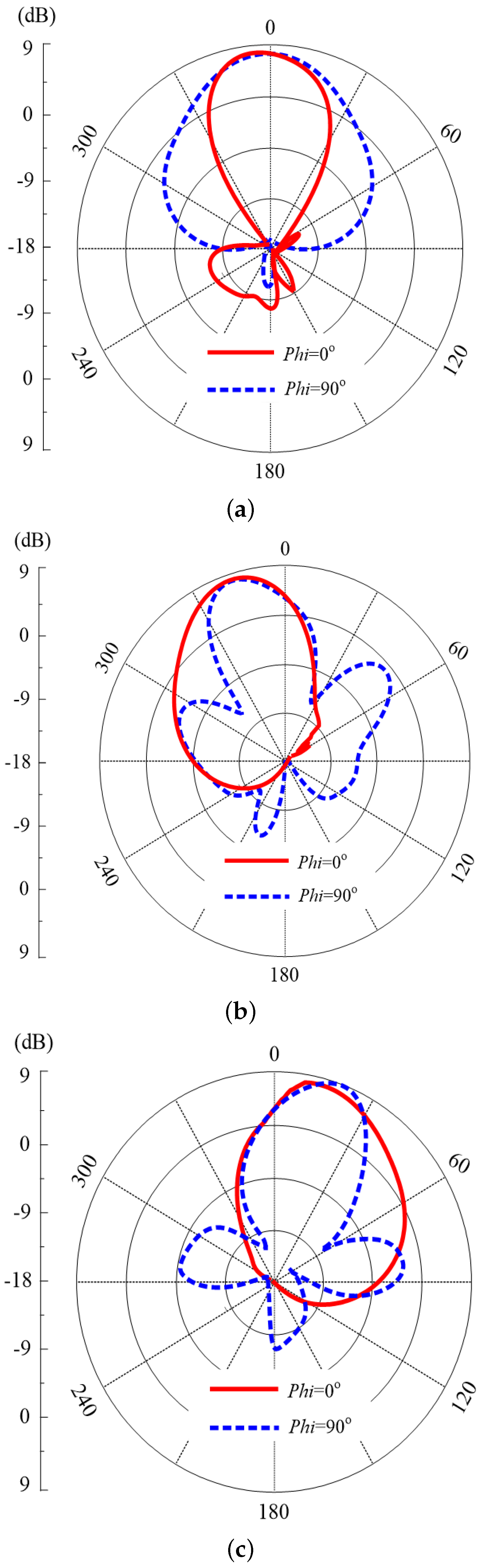
The measurements of the gain and radiation pattern of the proposed antenna were performed by the commercial ORBIT/FR far-field measurement system in a shielded radio-frequency anechoic chamber, as shown in Figure 9. The measured 2D radiation patterns at various frequencies (i.e., 26, 28, and 30 GHz) in the operational range of the impedance bandwidth are shown in Figure 10. The scanning angles for Mode-I, -II, and -III at 26 GHz are −19, 0, and 18.7; at 28 GHz, these angles are −18, 0, and 17.5; while at 30 GHz, they were found to be −16.9, 0, and 17.1, respectively. The slight difference between the beam-tilting angles was due to the phase differences at the various frequencies. Moreover, the slight asymmetry between the radiation patterns of Mode-II and Mode-III was due to fabrication tolerances and inaccuracy in the measured results.
The gain of the proposed antenna was also measured to strengthen the findings. At 28 GHz, the reported simulated and measured gain along with the simulated efficiency for Mode-I was 8.1 dB, 7.95 dB, and 82%, for Mode-II 7.5 dB, 7.23 dB, and 84%, and for Mode-III 7.54 dB, 7.3 dB, and 83%, respectively. The small deviation between the simulated and measured gain value was due to the presence of electrical wires; moreover, the practical model diode also affected the performance since lumped ports were used in the simulations. The presented antenna design can further be investigated for arrays and MIMO configurations [39,40,41,42].
4.3. Comparison with State-of-the-Art Works
As stated in the aforementioned discussion that phased-array antennas have the drawback of a bulky size, for a fair comparison, they were not compared with the proposed work. Table 3 presents the comparison of the proposed work with state-of-the-art works reported for similar applications. It can be concluded that the presented work offers the advantages of a compact size, a simpler geometry, low-loss switching circuitry (only two PIN diodes), and a high-gain characteristic with a good beam-tilting capability.
5. Conclusions
This paper presented a millimeter-wave monopole antenna, with a beam-switching functionality, capable of switching the antenna beam towards different directions (with an angle of ±18) using two PIN diodes introduced into the ground plane. The proposed antenna is characterized by a simple shape and compact size, along with good, measured performance in terms of return loss, operating bandwidth, stable high gain, and radiation efficiency. Therefore, the proposed antenna is a potential candidate for future millimeter-wave 5G communications and IoT technology.
Author Contributions
Conceptualization, H.Z.; Formal analysis, H.Z.; Investigation, H.Z.; Methodology, H.Z.; Project administration, S.M.A. and S.M.; Resources, M.H., S.I.N. and S.M.; Supervision, S.I.N., S.M.A. and S.M.; Validation, H.Z.; Writing—original draft, H.Z.; Writing—review and editing, M.H., S.I.N., S.M.A. and S.M. All authors have read and agreed to the published version of the manuscript.
Funding
This research received no external funding.
Conflicts of Interest
The authors declare no conflict of interest.
References
- Yang, S.; Zhang, C.; Pan, H.K.; Fathy, A.E.; Nair, V.K. Frequency-Reconfigurable Antennas for Multiradio Wireless Platforms. IEEE Microw. Mag. 2009, 10, 66–83. [Google Scholar] [CrossRef]
- Mohanta, H.C.; Kouzani, A.Z.; Mandal, S.K. Reconfigurable Antennas and Their Applications. Univers. J. Electr. Electron. Eng. 2019, 6, 239–258. [Google Scholar] [CrossRef]
- Haupt, R.L.; Lanagan, M. Reconfigurable Antennas. IEEE Antennas Propag. Mag. 2013, 55, 49–61. [Google Scholar] [CrossRef]
- Ojaroudi Parchin, N.; Jahanbakhsh Basherlou, H.; Al-Yasir, Y.I.A.; Abdulkhaleq, A.M.; Abd-Alhameed, R.A. Reconfigurable Antennas: Switching Techniques—A Survey. Electronics 2020, 9, 336. [Google Scholar] [CrossRef] [Green Version]
- Haider, N.; Caratelli, D.; Yarovoy, A.G. Recent Developments in Reconfigurable and Multiband Antenna Technology. Int. J. Antennas Propag. 2013, 869170. [Google Scholar] [CrossRef] [Green Version]
- Mahlaoui, Z.; Antonino-Daviu, E.; Ferrando-Bataller, M. Radiation Pattern Reconfigurable Antenna for IoT Devices. Int. J. Antennas Propag. 2021, 5534063. [Google Scholar] [CrossRef]
- Ojaroudi Parchin, N.; Jahanbakhsh Basherlou, H.; Al-Yasir, Y.I.A.; Abd-Alhameed, R.A.; Abdulkhaleq, A.M.; Noras, J.M. Recent Developments of Reconfigurable Antennas for Current and Future Wireless Communication Systems. Electronics 2019, 8, 128. [Google Scholar] [CrossRef] [Green Version]
- Saad, A.A.R.; Mohamed, H.A. Printed millimeter-wave MIMO-based slot antenna arrays for 5G networks. AEU—Int. J. Electron. Commun. 2019, 99, 59–69. [Google Scholar] [CrossRef]
- Shah, I.; Hayat, S.; Basir, A.; Zada, M.; Shah, S.; Ullah, S. Design and analysis of a hexa-band frequency reconfigurable antenna for wireless communication. AEU—Int. J. Electron. Commun. 2019, 98, 80–88. [Google Scholar] [CrossRef]
- Chen, X.; Zhao, Y. Dual-band polarization and frequency reconfigurable antenna using double layer metasurface. AEU—Int. J. Electron. Commun. 2018, 95, 82–87. [Google Scholar] [CrossRef]
- Naqvi, A.H.; Lim, S. Microfluidically Polarization-Switchable Metasurfaced Antenna. IEEE Antennas Wirel. Propag. Lett. 2018, 17, 2255–2259. [Google Scholar] [CrossRef]
- Hussain, N.; Jeong, M.J.; Park, J.; Kim, N. A Broadband Circularly Polarized Fabry-Perot Resonant Antenna Using A Single-Layered PRS for 5G MIMO Applications. IEEE Access 2019, 7, 42897–42907. [Google Scholar] [CrossRef]
- Hussain, N.; Park, I. Design of a wide-gain-bandwidth metasurface antenna at terahertz frequency. AIP Adv. 2017, 7, 055313. [Google Scholar] [CrossRef] [Green Version]
- Naqvi, A.H.; Lim, S. A Beam-Steering Antenna With a Fluidically Programmable Metasurface. IEEE Trans. Antennas Propag. 2019, 67, 3704–3711. [Google Scholar] [CrossRef]
- Tran, H.H.; Le, T.T. A metasurface based low-profile reconfigurable antenna with pattern diversity. AEU—Int. J. Electron. Commun. 2020, 115, 153037. [Google Scholar] [CrossRef]
- Naqvi, S.I.; Naqvi, A.H.; Arshad, F.; Riaz, M.A.; Azam, M.A.; Khan, M.S.; Amin, Y.; Loo, J.; Tenhunen, H. An Integrated Antenna System for 4G and Millimeter-Wave 5G Future Handheld Devices. IEEE Access 2019, 7, 116555–116566. [Google Scholar] [CrossRef]
- Kakhki, M.B.; Denidni, T.A. Beam Tilting Antenna Using FSS Layer for 5G Applications. In Proceedings of the 2018 IEEE International Symposium on Antennas and Propagation USNC/URSI National Radio Science Meeting, Boston, MA, USA, 8–13 July 2018; pp. 47–48. [Google Scholar] [CrossRef]
- Mantash, M.; Kesavan, A.; Denidni, T.A. Beam-Tilting Endfire Antenna Using a Single-Layer FSS for 5G Communication Networks. IEEE Antennas Wirel. Propag. Lett. 2018, 17, 29–33. [Google Scholar] [CrossRef]
- Esmail, B.A.F.; Majid, H.A.; Dahlan, S.H.; Abidin, Z.Z.; Rahim, M.K.A.; Abdullah, M.A.; Jusoh, M. Antenna beam tilting and gain enhancement using novel metamaterial structure at 28 GHz. In Proceedings of the 2018 IEEE International RF and Microwave Conference (RFM), Penang, Malaysia, 17–19 December 2018; pp. 53–56. [Google Scholar] [CrossRef]
- Awan, W.A.; Ghaffar, A.; Hussain, N.; Li, X.J. A Frequency Reconfigurable Flexible Antenna for Multiple Mobile Applications. In Proceedings of the 2019 IEEE Asia-Pacific Microwave Conference (APMC), Singapore, 10–13 December 2019; pp. 813–815. [Google Scholar] [CrossRef]
- Shakhirul, M.S.; Jusoh, M.; Lee, Y.S.; Husna, C.R.N. A Review of Reconfigurable Frequency Switching Technique on Micostrip Antenna. J. Phys. Conf. Ser. 2018, 1019, 012042. [Google Scholar] [CrossRef]
- Al Abbas, E.; Nguyen-Trong, N.; Mobashsher, A.T.; Abbosh, A.M. Polarization-Reconfigurable Antenna Array for Millimeter-Wave 5G. IEEE Access 2019, 7, 131214–131220. [Google Scholar] [CrossRef]
- Shereen, M.K.; Khattak, M.I.; Witjaksono, G. A brief review of frequency, radiation pattern, polarization, and compound reconfigurable antennas for 5G applications. J. Comput. Electron. 2019, 18, 1065–1102. [Google Scholar] [CrossRef]
- Ikram, M.; Nguyen-Trong, N.; Abbosh, A.M. Common-Aperture Sub-6 GHz and Millimeter-Wave 5G Antenna System. IEEE Access 2020, 8, 199415–199423. [Google Scholar] [CrossRef]
- Yang, X.; Xiao, J.; Wang, J.; Sheng, L. Compact Frequency Reconfigurable Antennas Based on Composite Right/Left-Handed Transmission Line. IEEE Access 2019, 7, 131663–131671. [Google Scholar] [CrossRef]
- Jilani, S.F.; Rahimian, A.; Alfadhl, Y.; Alomainy, A. Low-profile flexible frequency-reconfigurable millimetre-wave antenna for 5G applications. Flex. Print. Electron. 2018, 3, 035003. [Google Scholar] [CrossRef]
- Ali Esmail, B.; Majid, H.A.; Zainal Abidin, Z.; Haimi Dahlan, S.; Himdi, M.; Dewan, R.; Kamal A Rahim, M.; Al-Fadhali, N. Reconfigurable Radiation Pattern of Planar Antenna Using Metamaterial for 5G Applications. Materials 2020, 13, 582. [Google Scholar] [CrossRef] [Green Version]
- Esmail, B.A.F.; Majid, H.A.; Dahlan, S.H.; Zainal abidin, Z.; Himdi, M.; Dewan, R.; Rahim, M.K.A.; Ashyap, A.Y.I. Reconfigurable metamaterial structure for 5G beam tilting antenna applications. Waves Random Complex Media 2020, 1–14. [Google Scholar] [CrossRef]
- Abbas, S.M.; Esselle, K.P.; Ranga, Y.; Qin, P.Y. Reconfigurable antennas with narrowband and ultra wideband modes. In Proceedings of the 2015 IEEE MTT-S 2015 International Microwave Workshop Series on RF and Wireless Technologies for Biomedical and Healthcare Applications (IMWS-BIO), Taipei, Taiwan, 21–23 September 2015; pp. 56–57. [Google Scholar] [CrossRef]
- Jilani, S.F.; Abbas, S.M.; Esselle, K.P.; Alomainy, A. Millimeter-wave frequency reconfigurable T-shaped antenna for 5G networks. In Proceedings of the 2015 IEEE 11th International Conference on Wireless and Mobile Computing, Networking and Communications (WiMob), Abu Dhabi, United Arab Emirates, 19–21 October 2015; pp. 100–102. [Google Scholar] [CrossRef]
- Abbas, S.M.; Ranga, Y.; Esselle, K.P. A switchable printed antenna with a ground plane for 2.45/5 GHz wireless body area networks. In Proceedings of the 2015 International Workshop on Antenna Technology (iWAT), Seoul, Korea, 4–6 March 2015; pp. 27–29. [Google Scholar] [CrossRef]
- Awan, W.A.; Zaidi, A.; Hussain, N.; Iqbal, A.; Baghdad, A. Stub loaded, low profile UWB antenna with independently controllable notch-bands. Microw. Opt. Technol. Lett. 2019, 61, 2447–2454. [Google Scholar] [CrossRef]
- Balanis, C. Antenna Theory: Analysis and Design; Wiley: Hoboken, NJ, USA, 2016. [Google Scholar]
- Federal Communications Commission. FCC Establishes Procedures for First 5G Spectrum Auctions; Federal Communications Commission: Washington, DC, USA, 2018. [Google Scholar]
- Awan, W.A.; Hussain, N.; Le, T.T. Ultra-thin flexible fractal antenna for 2.45 GHz application with wideband harmonic rejection. AEU—Int. J. Electron. Commun. 2019, 110, 152851. [Google Scholar] [CrossRef]
- Naqvi, S.A. Miniaturized triple-band and ultra-wideband (UWB) fractal antennas for UWB applications. Microw. Opt. Technol. Lett. 2017, 59, 1542–1546. [Google Scholar] [CrossRef]
- JYEBAO Co. Ltd. Available online: www.jyebao.com.tw (accessed on 9 March 2020).
- MACOM. Available online: www.macom.com (accessed on 9 March 2020).
- Zahra, H.; Awan, W.A.; Hussain, N.; Abbas, S.M.; Mukhopadhyay, S. Helix Inspired 28 GHz Broadband Antenna with End-Fire Radiation Pattern. Comput. Mater. Contin. 2022, 70, 1935–1944. [Google Scholar] [CrossRef]
- Shaik, P.; Singya, P.K.; Bhatia, V. Performance analysis of QAM schemes for non-regenerative cooperative MIMO network with transmit antenna selection. AEU—Int. J. Electron. Commun. 2019, 107, 298–306. [Google Scholar] [CrossRef]
- Zahra, H.; Awan, W.A.; Ali, W.A.E.; Hussain, N.; Abbas, S.M.; Mukhopadhyay, S. A 28 GHz Broadband Helical Inspired End-Fire Antenna and Its MIMO Configuration for 5G Pattern Diversity Applications. Electronics 2021, 10, 405. [Google Scholar] [CrossRef]
- Parvez, S.; Singya, P.K.; Bhatia, V. On ASER Analysis of Energy Efficient Modulation Schemes for a Device-to-Device MIMO Relay Network. IEEE Access 2020, 8, 2499–2512. [Google Scholar] [CrossRef]
Figure 1.
Geometry of the proposed antenna: (a) front view, (b) side view, and (c) back view.
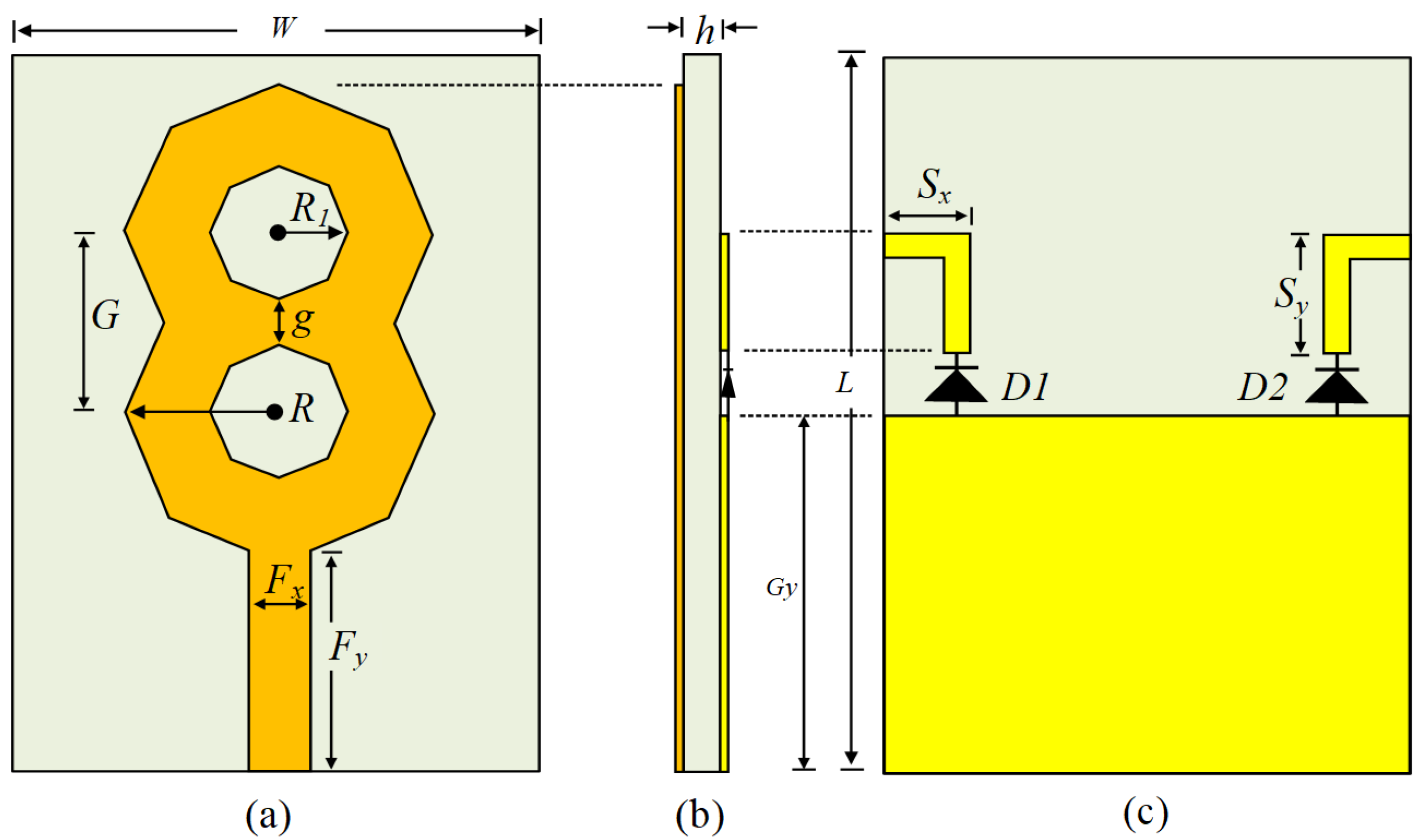
Figure 2.
Design evolution of the wideband monopole antenna.
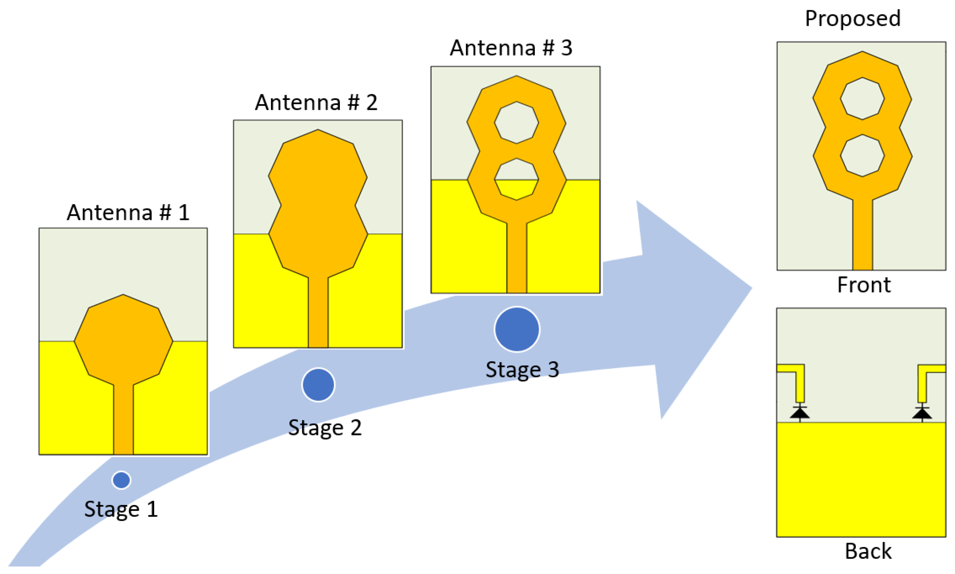
Figure 3.
characteristics of Antenna , Antenna , and Antenna .
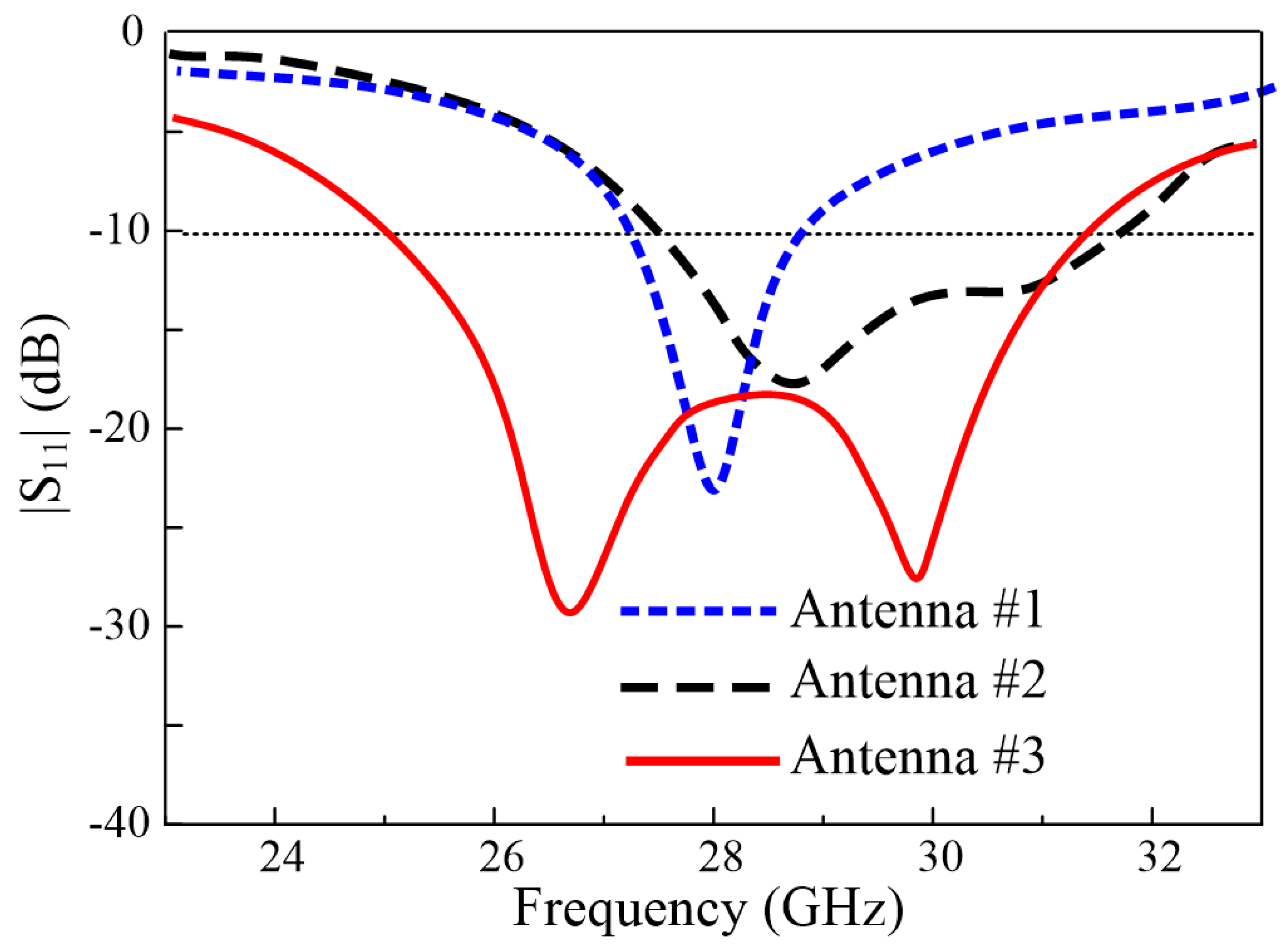
Figure 4.
characteristics of Antenna and Antenna (proposed antenna).
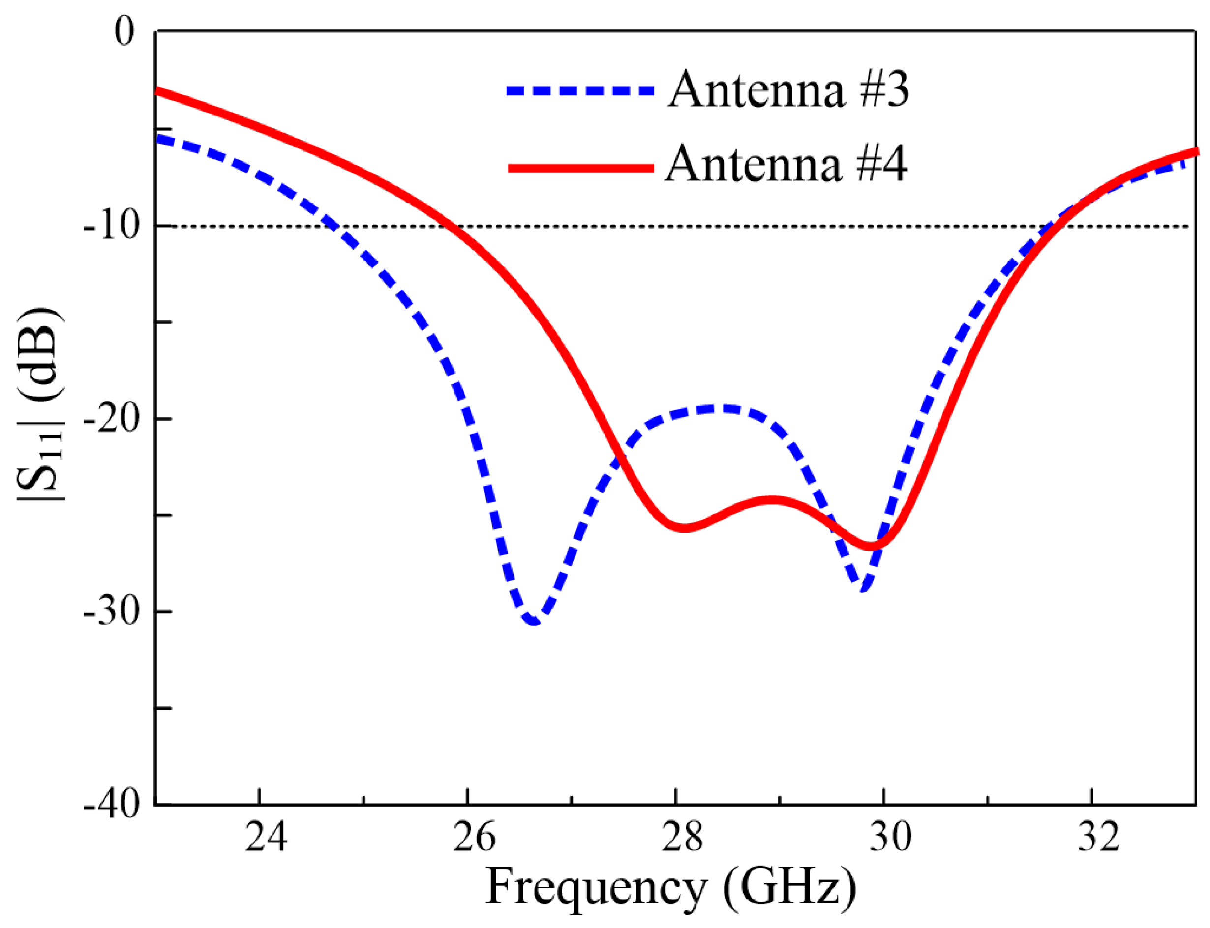
Figure 5.
Switchable radiation patterns of the proposed antenna for different switching modes at: (a) 26 GHz, (b) 28 GHz, and (c) 30 GHz.
Figure 5.
Switchable radiation patterns of the proposed antenna for different switching modes at: (a) 26 GHz, (b) 28 GHz, and (c) 30 GHz.
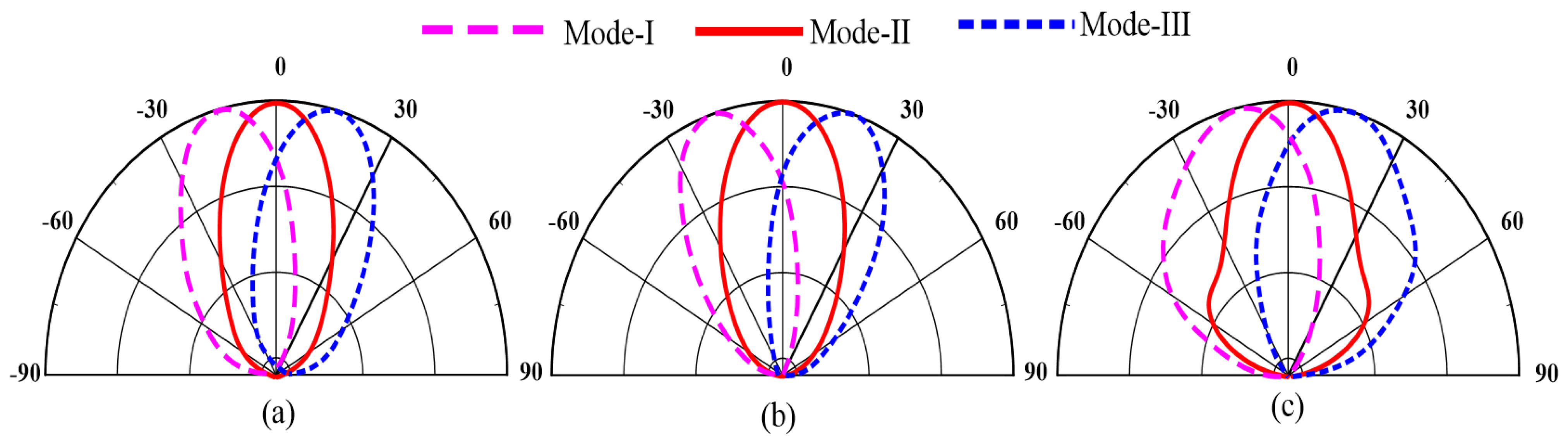
Figure 6.
Fabricated prototype of the proposed antenna.

Figure 7.
Equivalent circuit model PIN diode: (a) forward biased, (b) reverse biased, and (c) biasing circuit for the switching of the diode.
Figure 7.
Equivalent circuit model PIN diode: (a) forward biased, (b) reverse biased, and (c) biasing circuit for the switching of the diode.
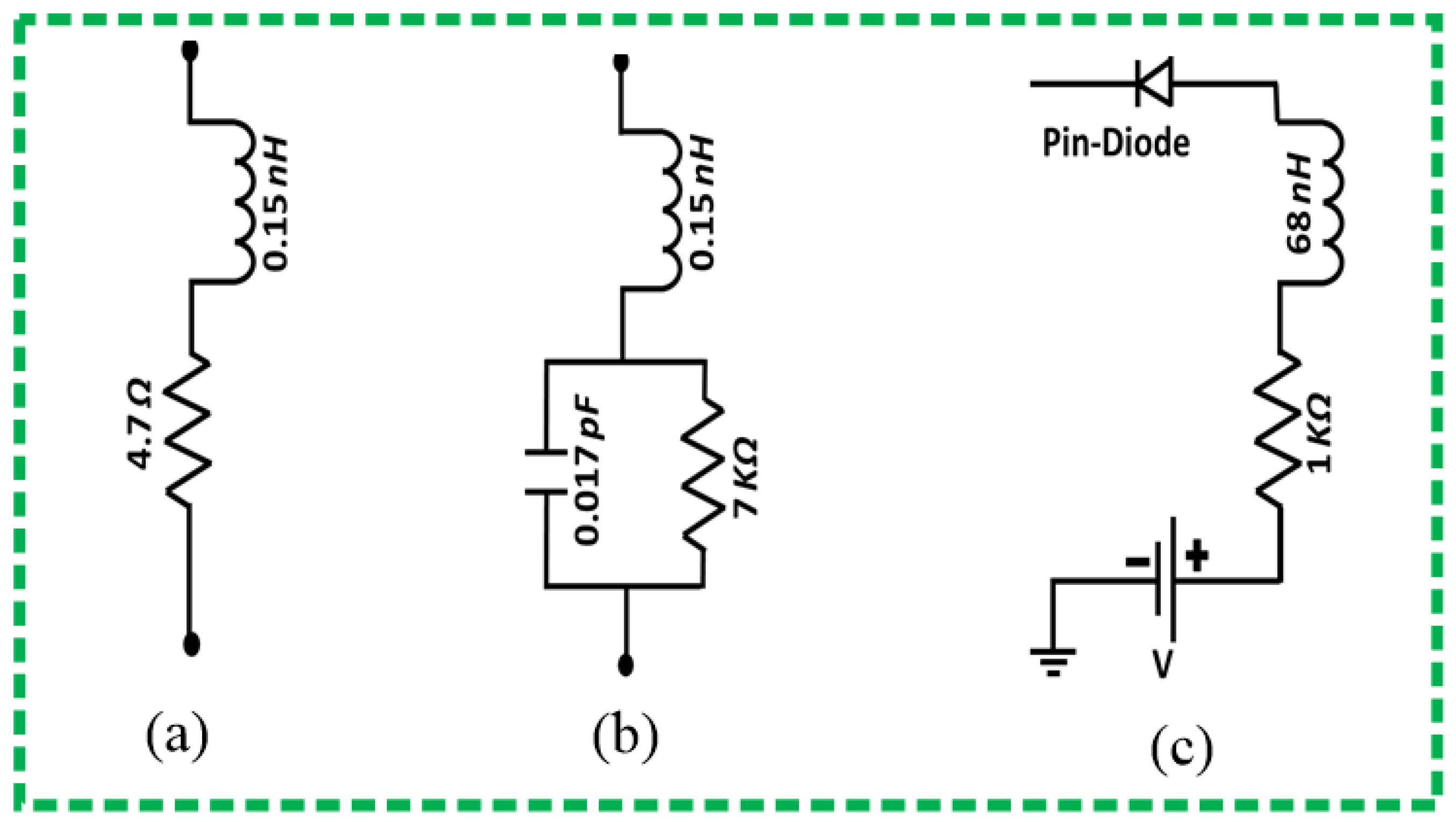
Figure 8.
Simulated and measured of the proposed antenna for different switching modes: (a) Mode-I (00), (b) Mode-II (01), and (c) Mode-III (10).
Figure 8.
Simulated and measured of the proposed antenna for different switching modes: (a) Mode-I (00), (b) Mode-II (01), and (c) Mode-III (10).

Figure 9.
Far-field measurement setup of the proposed antenna.
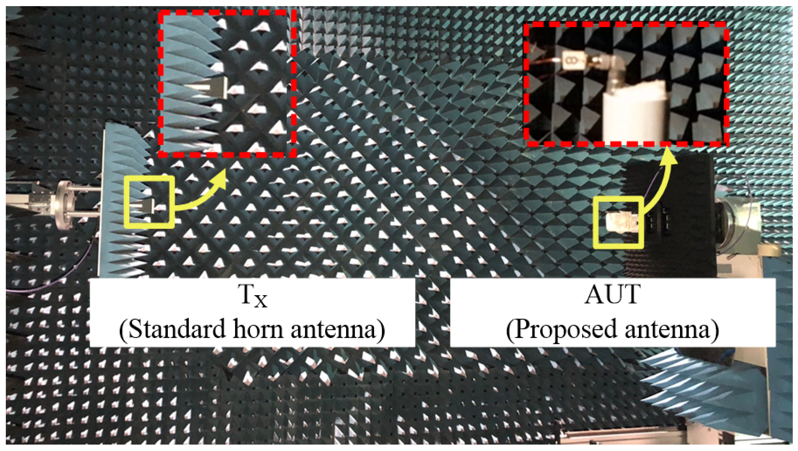
Figure 10.
Switchable measured radiation patterns of the proposed antenna for different switching modes: (a) Mode-I (00), (b) Mode-II (01), and (c) Mode-III (10).
Figure 10.
Switchable measured radiation patterns of the proposed antenna for different switching modes: (a) Mode-I (00), (b) Mode-II (01), and (c) Mode-III (10).

Table 1.
Optimized dimensions of the proposed design.
| Parameter | Value (mm) | Parameter | Value (mm) | Parameter | Value (mm) |
|---|---|---|---|---|---|
| L | 12 | R | 1 | F | 1 |
| W | 8.5 | G | 3 | F | 3.7 |
| R | 2.5 | g | 1 | 1.4 | |
| d | 0.4 | G | 6 | 2 |
Table 2.
Impedance bandwidth and main beam direction corresponding to different operating modes.
| Operating Mode | Diode D1 | Diode D2 | Simulated Bandwidth (GHz) | Measured Bandwidth (GHz) | Main Beam Direction (deg) |
|---|---|---|---|---|---|
| I | 0 | 0 | 25.1–31.2 | 25.4–30.8 | 0 |
| II | 0 | 1 | 24.9–31.5 | 26.4–31.4 | −18 |
| III | 1 | 0 | 25.1–31.2 | 26.35–31.4 | +18 |
Table 3.
Comparison of the proposed work with state-of-the-art works for similar applications.
| Ref. | Dimensions (mm) | Bandwidth (GHz) | Beam-Switching Angles (Theta) | Switching Technique | Peak Gain (dB) |
|---|---|---|---|---|---|
| [17] | 50 × 50 × 6 | 25–30 | 90 and 62 | Mechanical | 9 |
| [18] | 25.9 × 27.8 × 3.5 | 28–31 | 67, 90 and 119 | Mechanical | 9.6 |
| [19] | 17 × 18 × 0.254 | 24.5–31.7 | −25 and 24 | Mechanical | 5.2 |
| [27] | 12 × 16 × 0.254 | 25.8–29.2 | −27 and 30 | Ideal Switches | 6 |
| [28] | 12 × 16 × 0.254 | 25.2–29.7 | −31 and 34 | Ideal Switches | 6.5 |
| Proposed | 8.5 × 12 × 0.508 | 26.4–34.4 | −18, 0 and +18 | PIN diodes | 8.1 |
Publisher’s Note: MDPI stays neutral with regard to jurisdictional claims in published maps and institutional affiliations. |
© 2021 by the authors. Licensee MDPI, Basel, Switzerland. This article is an open access article distributed under the terms and conditions of the Creative Commons Attribution (CC BY) license (https://creativecommons.org/licenses/by/4.0/).
Share and Cite
MDPI and ACS Style
Zahra, H.; Hussain, M.; Naqvi, S.I.; Abbas, S.M.; Mukhopadhyay, S. A Simple Monopole Antenna with a Switchable Beam for 5G Millimeter-Wave Communication Systems. Electronics 2021, 10, 2870. https://doi.org/10.3390/electronics10222870
AMA Style
Zahra H, Hussain M, Naqvi SI, Abbas SM, Mukhopadhyay S. A Simple Monopole Antenna with a Switchable Beam for 5G Millimeter-Wave Communication Systems. Electronics. 2021; 10(22):2870. https://doi.org/10.3390/electronics10222870
Chicago/Turabian StyleZahra, Hijab, Musa Hussain, Syeda Iffat Naqvi, Syed Muzahir Abbas, and Subhas Mukhopadhyay. 2021. "A Simple Monopole Antenna with a Switchable Beam for 5G Millimeter-Wave Communication Systems" Electronics 10, no. 22: 2870. https://doi.org/10.3390/electronics10222870
Note that from the first issue of 2016, this journal uses article numbers instead of page numbers. See further details here.