
Carbon Fiber Biocompatibility for Implants

Abstract
:1. Introduction

| Material | Specific Gravity (g/cm3) | Tensile Strength (GPa) | Specific Strength (GPa) | Modulus of Elasticity (GPa) | Specific Modulus (GPa) |
|---|---|---|---|---|---|
| Carbon Fiber | 1.6–2.2 | 1.5–5.65 | 0.70–3.12 | 228–790 | 106–407 |
| Steel Wire | 7.9 | 2.39 | 0.30 | 210 | 26.6 |
2. Carbon-Fiber Composite Bone Implant Material
2.1. Materials and in Vivo Animal Model
2.2. Animal Testing
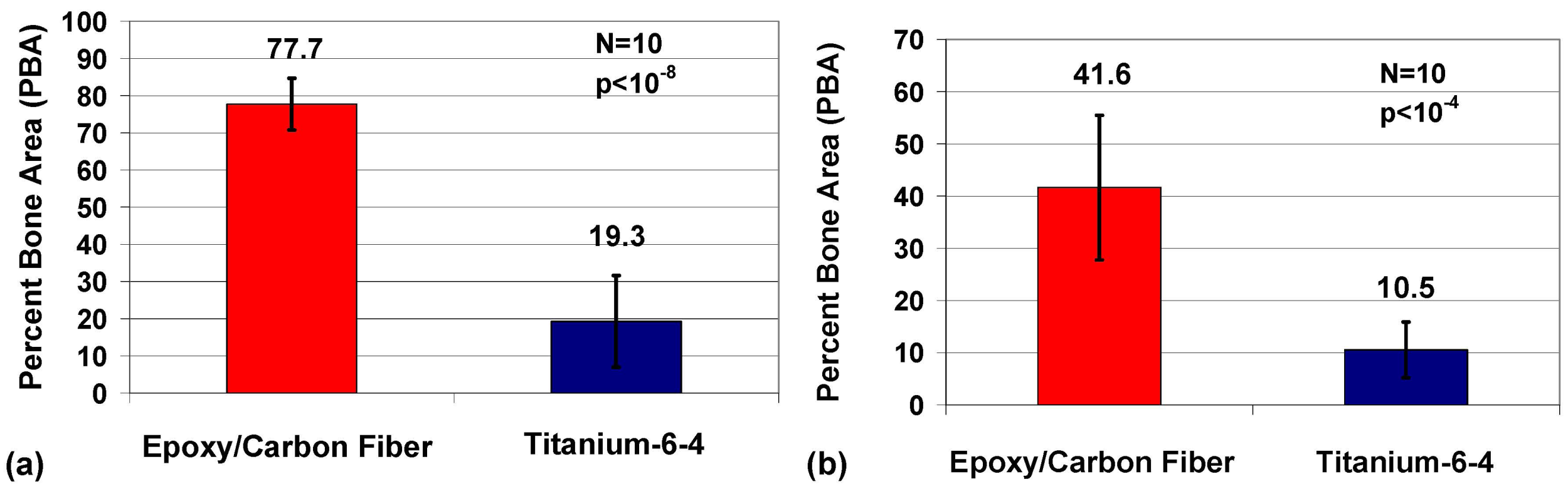
2.3. Histomorphic Analysis
2.4. Statistics

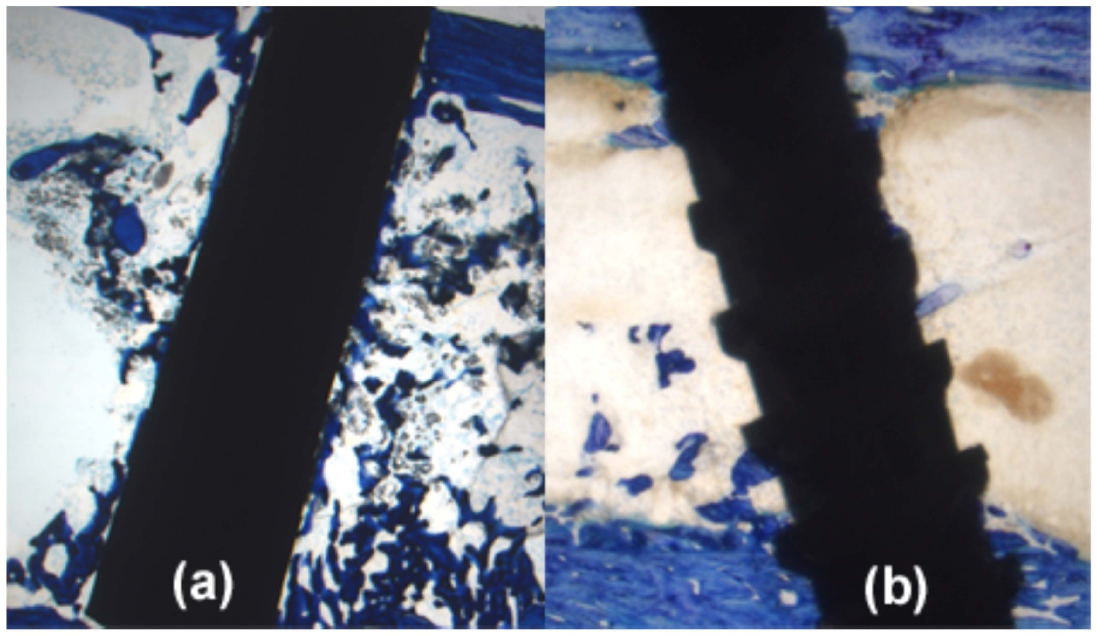
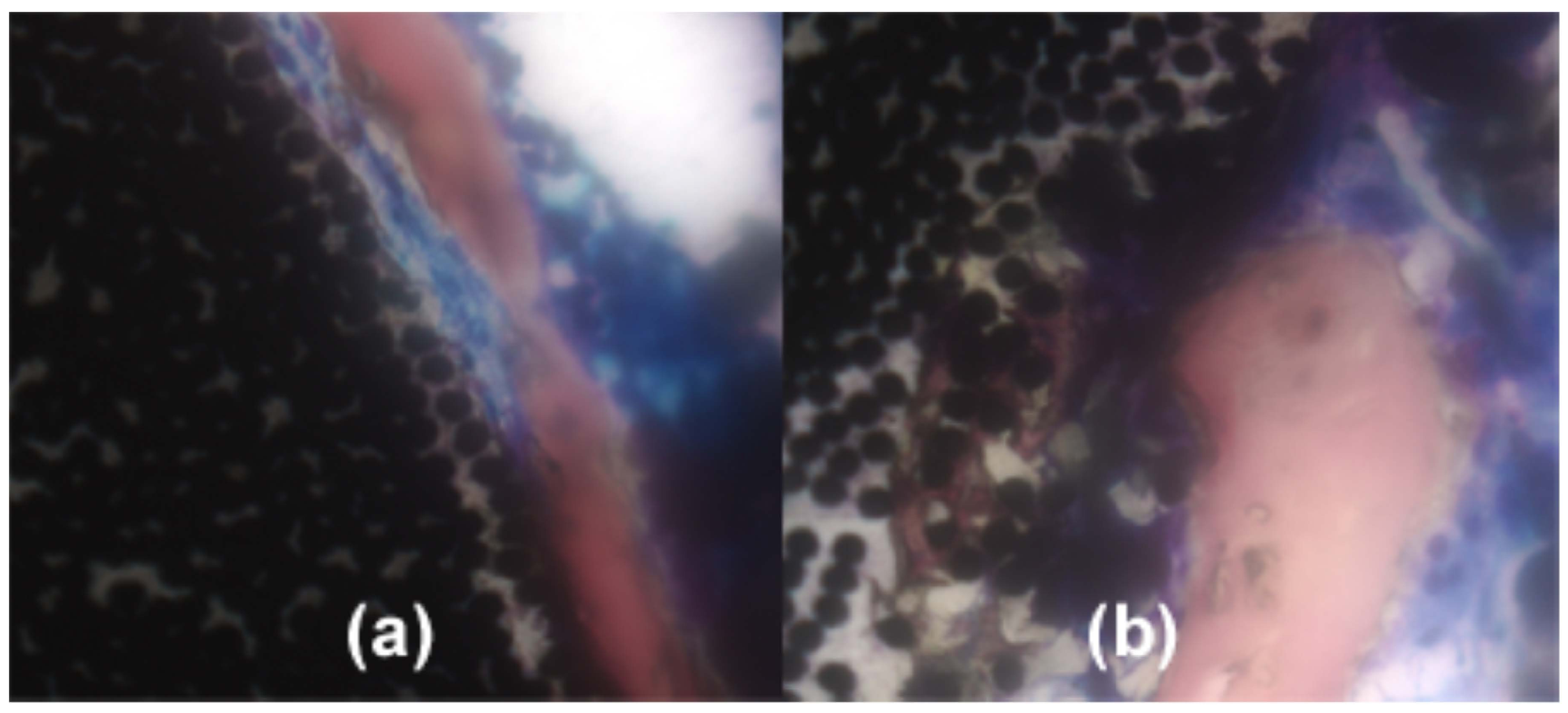
2.5. Imaging


3. Biological Implant Considerations
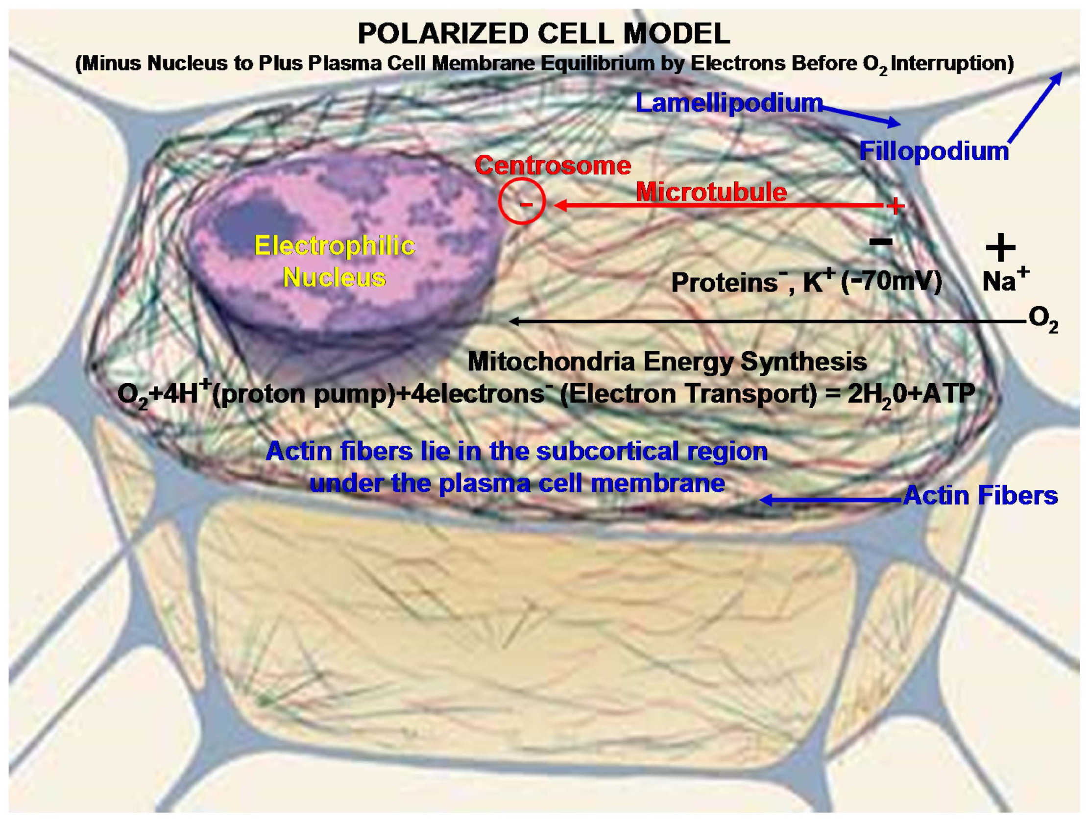
3.1. Metabolic Cell Oxygen Demands
3.2. Cell Motility

4. Biomaterial Implant Considerations
4.1. Carbon Fiber Biocompatible Conductivity vs. Metal Acids
4.2. Polymer Estrogen Influence
4.3. Fiber-Reinforced Composite Design Capability
4.4. Carbon Fiber Percolation Threshold with Cell Motility
5. Conclusions
Acknowledgments
Conflicts of Interest
References
- Callister, W.D. Materials Science and Engineering, 4th ed.; John Wiley & Sons: New York, NY, USA, 1997. [Google Scholar]
- Chawla, K.K. Carbon Fibers. In Composite Materials, 2nd ed.; Springer: New York, NY, USA, 1998; pp. 23–34. [Google Scholar]
- Peters, S.T. Handbook of Composites, 2nd ed.; Chapman and Hall: New York, NY, USA, 1998. [Google Scholar]
- Ali, M.S.; French, T.A.; Hastings, G.W.; Rae, T.; Rushton, N.; Ross, E.R.S.; Wynn-Jones, C.H. Carbon fibre composite bone plates. J. Bone Jt. Surg. 1990, 72, 586–591. [Google Scholar]
- Pimberton, D.J.; McKibbin, B.; Savage, R.; Tayton, K.; Stuart, D. Carbon-Fibre Reinforced Plates for Problem Fractures. J. Bone Jt. Surg. 1992, 74, 88–92. [Google Scholar]
- Dikbas, I.; Tanalp, J. An Overview of Clinical Studies on Fiber Post Systems. Sci. World J. 2013, 2013. [Google Scholar] [CrossRef] [PubMed]
- Tarallo, L.; Mugnai, R.; Adani, R.; Zambianchi, F.; Catani, F. A new volar plate made of carbon-fiber-reinforced polyetheretherketon for distal radius fracture: Analysis of 40 cases. J. Orthop. Traumatol. 2014, 15, 277–283. [Google Scholar] [CrossRef] [PubMed] [Green Version]
- Blazewicz, M. Carbon materials in the treatment of soft and hard tissue injuries. Eur. Cells Mater. 2001, 2, 21–29. [Google Scholar]
- Petersen, R.C. Bisphenyl-Polymer/Carbon-Fiber-Reinforced Composite Compared to Titanium Alloy Bone Implant. Int. J. Polym. Sci. 2011, 2011. [Google Scholar] [CrossRef] [PubMed]
- Guitchounts, G.; Markowitz, J.E.; Liberti, W.A.; Gardner, T.J.A. Carbon-fiber electrode array for long-term neural recording. J. Neural Eng. 2013, 10. [Google Scholar] [CrossRef] [PubMed]
- Pilliar, R.M.; Blackwell, R.; Macnab, I.; Cameron, H.U. Carbon fiber-reinforced bone cement in orthopedic surgery. J. Biomed. Mater. Res. 1976, 10, 893–906. [Google Scholar] [CrossRef] [PubMed]
- Saha, S.; Pal, S. Mechanical characterization of commercially made carbon-fiber-reinforced polymethylmethacrylate. J. Biomed. Mater. Res. 1986, 20, 817–826. [Google Scholar] [CrossRef] [PubMed]
- Amis, A.A. Anterior cruciate ligament replacement. J. Bone Jt. Surg. 1989, 71, 819–824. [Google Scholar]
- Price, R.L.; Elias, K.L.; Haberstroh, K.M.; Webster, T.J. Small diameter, high surface energy carbon nanofiber formulations that selectively increase osteoblast function. Mater. Res. Soc. Symp. Proc. 2002, 711. [Google Scholar] [CrossRef]
- Antoniac, I. Biologically Responsive Biomaterials for Tissue Engineering; Springer: New York, NY, USA, 2013; pp. 173–199. [Google Scholar]
- Balasubramanian, M. Composite Materials and Processing; CRC Press Taylor & Francis Group: Boca Raton, FL, USA, 2014; pp. 31–82. [Google Scholar]
- Park, J.B.; Lakes, R.S. Hard Tissue Replacement. In Biomaterials an Introduction, 2nd ed.; Plenum Press: New York, NY, USA, 1992; p. 347. [Google Scholar]
- Chung, D.D.L. Review electrical applications of carbon materials. J. Mater. Sci. 2004, 39, 2645–2661. [Google Scholar] [CrossRef]
- Thomassin, J.-M.; Jérôme, C.; Pardoen, T.; Bailly, C.; Huynen, I.; Detrembleur, C. Polymer/carbon based composites as electromagnetic interference (EMI) shielding materials. Mater. Sci. Eng. R 2013, 74, 211–232. [Google Scholar] [CrossRef]
- Ramadin, Y.; Jawad, S.A.; Musameh, S.M.; Ahmad, M.; Zihlif, A.M.; Paesano, A.; Martuscelli, E.; Ragosta, G. Electrical and electromagnetic shielding behavior of laminated epoxy carbon fiber composite. Polym. Int. 1994, 34, 145–150. [Google Scholar] [CrossRef]
- Düppenbecker, P.M.; Wehner, J.; Renz, W.; Lodomez, S.; Truhn, D.; Marsden, P.K.; Schulz, V. Gradient transparent RF housing for simultaneous PET/MRI using carbon fiber composites. In Proceedings of the IEEE Nuclear Science Symposium and Medical Imaging Conference Record (NSS/MIC), Anaheim, CA, USA, 27 October–3 November 2012; pp. 3478–3480.
- Park, J.B.; Okabe, T.; Takeda, N. New concept for modeling the electromechanical behavior of unidirectional carbon-fiber-reinforced plastic under tensile loading. Smart Mater. Struct. 2003, 12, 105–114. [Google Scholar] [CrossRef]
- Park, B.J.; Lakes, R.S. Structure Property Relationships of Biological Materials. In Biomaterials an Introduction, 2nd ed.; Plenum Press: New York, NY, USA, 1992; pp. 64, 204. [Google Scholar]
- Sugawara, K.; Yugami, A.; Kojima, A. Voltammetric detection of biological molecules using chopped carbon fiber. Jpn. Soc. Anal. Chem. 2010, 26, 1059–1063. [Google Scholar] [CrossRef]
- Stout, D.A.; Raimondo, E.; Webster, T.J. Improved cardiomyocyte functions of carbon nanofiber cardiac patches. Mater. Res. Soc. Symp. Proc. 2012, 1414. [Google Scholar] [CrossRef]
- Stout, D.A.; Basu, B.; Webster, T.J. Poly(lactic-co-glycolic acid): Carbon nanofiber composites for myocardial tissue engineering applications. Acta Biomater. 2011, 7, 3101–3112. [Google Scholar] [CrossRef] [PubMed]
- Ratner, B.D.; Hoffman, A.S.; Schoen, F.J.; Lemons, J.E. Composites. In Biomaterials Science, 2nd ed.; Elsevier: San Diego, CA, USA, 2004; p. 183. [Google Scholar]
- Mendes, D.G.; Angel, D.; Grishkan, A.; Boss, J. Histological response to carbon fibre. J. Bone Jt. Surg. 1985, 67, 645–649. [Google Scholar]
- Dunn, M.G. Anterior cruciate ligament prostheses. Encyclopedia of Sports Medicine and Science. Fahey, T.D., Ed.; Available online: http://sportsci.org (accessed on 1 October 2015).
- McCracken, M.S.; Lemons, J.E.; Rahemtulla, F.; Prince, C.W.; Feldman, D. Bone response to titanium alloy implants placed in diabetic rats. Int. J. Oral Maxillofac. Implant. 2000, 15, 345–354. [Google Scholar]
- Helmlinger, G.; Yuan, F.; Dellian, M.; Jain, R.K. Interstitial pH and pO2 gradients in solid tumors in vivo: High-resolution measurements reveal a lack of correlation. Nat. Med. 1997, 3, 177–182. [Google Scholar] [CrossRef] [PubMed]
- Gillies, R.J. Introduction. In The Tumour Microenvironment: Causes and Consequences of Hypoxia and Acidity; John Wiley and Sons: New York, NY, USA, 2001; pp. 1–6. [Google Scholar]
- Weinberg, R.A. Dialogue Replaces Monologue: Heterotypic Interactions and the Biology of Angiogenesis. In The Biology of Cancer; Garland Science Taylor and Francis Group: New York, NY, USA, 2007; pp. 556–557. [Google Scholar]
- Petersen, R.C. Mitochondria. In Micromechanics/Electron Interactions for Advanced Biomedical Research; Lambert: Saarbrücken, Germany, 2011; pp. 316–322. [Google Scholar]
- Michael, J.; Sircar, S. Metabolic Pathways. In Fundamentals of Medical Physiology; Michael, J., Ed.; Thieme: New York, NY, USA, 2011; pp. 467–469. [Google Scholar]
- Copstead, L.-E.; Banasik, J. Pathophysiology, 6th ed.; Elsevier Saunders: St. Louis, MO, USA, 2005; p. 417. [Google Scholar]
- Weinberg, R.A. The Biology and Genetics of Cells and Organisms. In The Biology of Cancer; Garland Science: New York, NY, USA, 2007; p. 15. [Google Scholar]
- McMurry, J. Organic Chemistry, 6th ed.; Thompson Brooks/Cole: Belmont, CA, USA, 2004; pp. 10–11. [Google Scholar]
- Brown, W.H.; Poon, T. Introduction to Organic Chemistry, 5th ed.; Wily/John Wiley & Sons, Inc.: Hoboken, NJ, USA, 2014; pp. 8–9. [Google Scholar]
- Li, Z.; Hannigan, M.; Mo, Z.; Liu, B.; Lu, W.; Wu, Y.; Smrcka, A.V.; Wu, G.; Li, L.; Liu, M.; et al. Directional sensing requires G-beta-gamma-mediated PAK1 and PIX-alpha-dependent activation of Cdc42. Cell 2003, 114, 215–227. [Google Scholar] [CrossRef]
- Hattori, H.; Subramanian, K.K.; Sakai, J.; Jia, Y.; Li, Y.; Porter, T.F.; Laison, F.; Savraj, B.; Kasorn, A.; Jo, H.; et al. Small-molecule screen identifies reactive oxygen species as key regulators of neutrophil chemotaxis. PNAS 2010, 107, 3546–3551. [Google Scholar] [CrossRef] [PubMed]
- Parisi, F.; Vidal, M. Epithelial delamination and migration: Lessons from Drosophila. Cell Adhes. Migr. 2011, 5, 366–372. [Google Scholar] [CrossRef]
- Barth, A.I.M.; Caro-Gonzalez, H.Y.; Nelson, W.J. Role of adenomatous polyposis coli (APC) and microtubules in directional cell migration and neuronal polarization. Semin. Cell Dev. Biol. 2008, 19, 245–251. [Google Scholar] [CrossRef] [PubMed]
- Dent, E.W.; Gupton, S.L.; Gertler, F.B. The growth cone cytoskeleton in axon outgrowth and guidance. Cold Spring Harb. Perspect. Biol. 2011, 3. [Google Scholar] [CrossRef] [PubMed]
- Ratner, B.D.; Hoffman, A.S.; Schoen, F.J.; Lemons, J.E. Cells and Cell Injury. In Biomaterials Science; Elsevier: San Diego, CA, USA, 2004; p. 251. [Google Scholar]
- Lindberg, U.; Karlsson, R.; Lassing, I.; Schutt, C.E.; Höglund, A.S. The microfilament system and malignancy. Semin. Cancer Biol. 2008, 18, 2–11. [Google Scholar] [CrossRef] [PubMed]
- Michael, J.; Sircar, S. Resting Membrane Potential. In Fundamentals of Medical Physiology; Michael, J., Ed.; Thieme: New York, NY, USA, 2011; p. 33. [Google Scholar]
- Vinogradova, T.; Miller, P.M.; Kaverina, I. Microtubule network asymmetry in motile cells: Role of Golgi-derived array. Cell Cycle 2009, 8, 2168–2174. [Google Scholar] [CrossRef] [PubMed]
- Pokorný, J.; Jandová, A.; Nedbalová, M.; Jelínok, F.; Cifra, M.; Kučara, O.; Havelka, D.; Vrba, J.; Vrba, J., Jr.; Čoček, A.; et al. Mitochondrial metabolism-neglected link of cancer transformation and treatment. Prague Med. Rep. 2012, 113, 81–94. [Google Scholar] [CrossRef] [PubMed]
- Petersen, R.C. Reactive Secondary Sequence Oxidative Pathology Polymer Model and Antioxidant Tests. Int. Res. J. Pure Appl. Chem. 2012, 2, 247–285. [Google Scholar] [CrossRef] [PubMed]
- Jones, D.A. Principles and Prevention of Corrosion, 2nd ed.; Prentice Hall: Upper Saddle River, NJ, USA, 1996; p. 7. [Google Scholar]
- Anusavice, K.J. Electrochemical Corrosion. In Phillips’ Science of Dental Materials, 11th ed.; Saunders: St. Louis, MO, USA, 2003; pp. 58–59. [Google Scholar]
- Gittens, R.A.; Olivares-Navarrete, R.; Tannenbaum, R.; Boyan, B.D.; Schwartz, Z. Electrical implications of corrosion for osseointegration of titanium implants. J. Dent. Res. 2011, 90, 1389–1397. [Google Scholar] [CrossRef] [PubMed]
- Zumdahl, S.S. The Lewis Acid-Base Model. In Chemistry; D.C. Heath and Company: Lexington, MA, USA, 1993; pp. 680–682. [Google Scholar]
- McMurry, J. Polar Covalent Bonds; Acids and Bases. In Organic Chemistry; Brooks/Cole-Thomson: Belmont, CA, USA, 2004; pp. 51–53. [Google Scholar]
- Dodds, E.C.; Lawson, W. Synthetic estrogenic agents without the phenanthrene nucleus. Nature 1936, 137. [Google Scholar] [CrossRef]
- Lewis, J.B.; Rueggeberg, F.A.; Lapp, C.A.; Ergle, J.W.; Schuster, G.S. Identification and characterization of estrogenlike components in commercial resin-based dental restorative materials. Clin. Oral Investig. 1999, 3, 107–113. [Google Scholar] [CrossRef] [PubMed]
- Gennari, L.; Nuti, R.; Bilezikian, J.P. Aromatase activity and bone homeostasis in men. J. Clin. Endocrinol. Metab. 2004, 89, 5898–5907. [Google Scholar] [CrossRef] [PubMed]
- Okazaki, R.; Inoue, D.; Shibata, M.; Saika, M.; Kido, S.; Ooka, H.; Tomitama, H.; Sakamoto, Y.; Matsumoto, T. Estrogen promotes early osteoblast differentiation and inhibits adipocyte differentiation in mouse bone marrow stromal cell lines that express estrogen receptor (ER) α or β. Endocrinology 2002, 143, 2349–2356. [Google Scholar] [PubMed]
- Toda, K.; Miyaura, C.; Okada, T.; Shizuta, Y. Dietary bisphenol A prevent ovarian degeneration and bone loss in female mice lacking the aromatase gene (Cyp 19). Eur. J. Biochem. 2002, 269, 2214–2222. [Google Scholar] [CrossRef] [PubMed]
- Radzikowska, J.; Gajowik, A.; Dorzyńska, M. Induction of micronuclei in peripheral blood and bone marrow reticulocytes of male mice after subchronic exposure to X-rays and bisphenol A. Rocz. Panstw. Zakl. Hig. 2012, 63, 17–23. [Google Scholar] [PubMed]
- Michael, J.; Sircar, S. Ovarian Hormones-Physiologic Actions. In Fundamentals of Medical Physiology; Michael, J., Ed.; Thieme: New York, NY, USA, 2011; p. 535. [Google Scholar]
- Pelch, K.E.; Carleton, S.M.; Phillips, C.L.; Nagel, S.C. Developmental exposure to xenoestrogens at low doses alters femur length and tensile strength in adult mice. Biol. Reprod. 2011, 86, 1–9. [Google Scholar] [CrossRef] [PubMed]
- Atkins, P. Interaction between Dipoles-Intermolecular Forces. In Physical Chemistry, 5th ed.; W.H. Freeman and Company: New York, NY, USA, 1994; pp. 763–771. [Google Scholar]
- Park, B.J.; Lakes, R.S. Hard Tissue Replacement. In Biomaterials an Introduction, 2nd ed.; Plenum Press: New York, NY, USA, 1992; pp. 293, 294. [Google Scholar]
- Huang, Z.-M.; Fujihara, K. Stiffness and strength design of composite bone plates. Compos. Sci. Technol. 2005, 65, 73–85. [Google Scholar] [CrossRef]
- Bagheri, Z.S.; Avval, P.T.; Bougherara, H.; Aziz, M.S.R.; Schemitsch, E.H.; Zdero, R. Biomechanical analysis of a new carbon fiber/flax/epoxy bone fracture plate shows less stress shielding compared to a standard clinical metal plate. Transactions of the ASME. J. Biomed. Eng. 2014, 136. [Google Scholar] [CrossRef]
- Chawla, K.K. Micromechanics of Composites. In Composite Materials, 2nd ed.; Springer: New York, NY, USA, 1998; pp. 303–346. [Google Scholar]
- Petersen, R.C.; Lemons, J.E.; McCracken, M.S. Micromechanics for Fiber Volume Percent with a Photocure Vinyl Ester Composite. Polym. Compos. 2007, 28, 294–310. [Google Scholar] [CrossRef] [PubMed]
- Petersen, R.C.; Lemons, J.E.; McCracken, M.S. Fracture toughness micromechanics by energy methods for a photocure vinyl ester composite. Polym. Compos. 2007, 28, 311–324. [Google Scholar] [CrossRef] [PubMed]
- Petersen, R.C.; Lemons, J.E.; McCracken, M.S. Stress-transfer micromechanics for fiber length in a photocure vinyl ester composite. Polym. Compos. 2006, 27, 153–169. [Google Scholar] [CrossRef] [PubMed]
- Římská, Z.; Křesálek, V.; Śpaček, J. AC conductivity of carbon fiber-polymer matrix composites at the percolation threshold. Polym. Compos. 2002, 23, 95–103. [Google Scholar]
- Park, J.B.; Hwang, T.K.; Doh, Y.D. Experimental and numerical study of the electrical anisotropy in unidirectional carbon-fiber-reinforced polymer composites. Smart Mater. Struct. 2007, 15, 57–66. [Google Scholar] [CrossRef]
© 2016 by the author; licensee MDPI, Basel, Switzerland. This article is an open access article distributed under the terms and conditions of the Creative Commons by Attribution (CC-BY) license (http://creativecommons.org/licenses/by/4.0/).
Share and Cite
Petersen, R. Carbon Fiber Biocompatibility for Implants. Fibers 2016, 4, 1. https://doi.org/10.3390/fib4010001
Petersen R. Carbon Fiber Biocompatibility for Implants. Fibers. 2016; 4(1):1. https://doi.org/10.3390/fib4010001
Chicago/Turabian StylePetersen, Richard. 2016. "Carbon Fiber Biocompatibility for Implants" Fibers 4, no. 1: 1. https://doi.org/10.3390/fib4010001