Article

In Situ Synthesis and Electrophoretic Deposition of NiO/Ni Core-Shell Nanoparticles and Its Application as Pseudocapacitor

1
Instituto de Cerámica y Vidrio, Spanish National Research Council (CSIC) Madrid, 28049, Spain
2
I.U.I Química Fina y Nanoquímica, Departamento Química Inorgánica e Ingeniería Química, Universidad de Córdoba, Córdoba, 14014, Spain
*
Author to whom correspondence should be addressed.
Coatings 2017, 7(11), 193; https://doi.org/10.3390/coatings7110193
Submission received: 29 September 2017 / Revised: 30 October 2017 / Accepted: 4 November 2017 / Published: 8 November 2017
(This article belongs to the Special Issue Electrophoretic Deposition)

Abstract

:
A simple, low cost and transferable colloidal processing method and the subsequent heat treatment has been optimized to prepare binder-free electrodes for their application in supercapacitors. NiO/Ni core–shell hybrid nanostructures have been synthetized by heterogeneous precipitation of metallic Ni nanospheres onto NiO nanoplatelets as seed surfaces. The electrophoretic deposition (EPD) has been used to shape the electroactive material onto 3D substrates such as Ni foams. The method has allowed us to control the growth and the homogeneity of the NiO/Ni coatings. The presence of metallic Nickel in the microstructure and the optimization of the thermal treatment have brought several improvements in the electrochemical response due to the connectivity of the final microstructure. The highest specific capacitance value has been obtained using a thermal treatment of 325 °C during 1 h in Argon. At this temperature, necks formed among ceramic-metallic nanoparticles preserve the structural integrity of the microstructure avoiding the employment of binders to enhance their connectivity. Thus, a compromise between porosity and connectivity should be established to improve electrochemical performance.

1. Introduction

Recent studies on energy storage devices are giving rise to constant progresses in nanoscience. New features of hybrid/electric vehicles and the intermittent renewable energies production need storage devices, such as supercapacitors. For these applications, the electrodes should be able to provide high power density, excellent reversibility and long cycle life. Typically, supercapacitors exhibit 20–200 times larger capacitance per unit of mass or volume than conventional capacitors. Depending on the charge-storage mechanism there are electrical double-layer capacitors (EDLC), mainly based on carbon materials [1,2] which storage the energy through ions accumulation at the electrode/electrolyte interface. In addition, pseudocapacitors, relayed on transition-metal oxides and conducting polymers, which store the energy through faradic reactions on the electrode surface in the appropriate potential window. Conducting polymers are easy to process due to its mechanical flexibility. However, polymers are easily degradable due to their bad stability, which results in a low cyclability. In contrast, transition metal oxides are robust and present higher capacitances and better cyclability. Because of these reasons, metal oxides have been proposed as an interesting alternative.
Among transition metals, the ruthenium oxides have showed the best capacitance response. It offers a very good cyclability during thousands of cycles, due to its high thermal and chemical stability, but the viability of those electrodes is limited because of its elevated cost [3]. The high price of this oxide have boosted the quest of new ones cheaper with high performances, for instance Cobalt, Manganese or Nickel oxides [4,5,6,7]. In particular, nickel oxide has received great attention due to its high theoretical specific capacitance of 3750 F/g [8], multiple reversible electrochemical reactions, ready availability and low cost [9].
There are many studies in the bibliography about synthesis, processing and characterization of pseudocapacitors based on Ni. Most authors usually carry out the processing of the electroactive material with subsequent mixing with binders for slurry formation and pressing onto metallic substrates. However, the consolidation of the electroactive material is not considered. The research works developed by Feng et al. [10], Zhang et al. [11] and Li et al. [12] are mainly focused on the synthesis of nanostructures, and they do not consider the influence of the processing parameters in the final electrochemical behavior.
Several studies have been developed in order to connect the effects of morphology, porosity and specific surface area with the electrochemical behavior. The main problem of these ceramic semiconductors (metallic oxides) is their low electrical connectivity between particles. Metal oxides are ceramic compounds, which microstructure should be consolidated by a sintering process with a specific heat treatment after shaping. This entails the obtaining of robust electrodes with well-connected particles, avoiding the use of well-known binders and/or additive like carbon black (CB), acetylene black, PVDF, PTFE used to increase the connectivity. In this way there are many published reports focusing on the improvement of the performance of the metal oxide electrodes in pseudocapacitors. In the case of NiO the use of different method to prepare electrodes for supercapacitor has been summarized previously in recent works [6,13]. Others authors prefer the application of sophisticate processing routes, which sometimes includes shaping and sintering simultaneously. For instance Kurra et al. employ CBD for the fabrication of micropseudocapacitors based on Ni(OH)2 [14]. Liu et al. use laser ablation in liquid (LAL) [15] and Jiang et al. work with chemical vapor deposition (CVD) [16].
From the final eighties, advances in colloidal chemistry knowledge have provided the necessary milestones for successfully applied colloidal processing methods in the reliable manufacture of nanostructures with final specific properties. The colloidal techniques involve the manipulation and control of the interparticle forces in the suspensions of powders in liquid media. This is a key step to break down weak agglomerates, stabilize and facilitate powders mixing, removing heterogeneities and defects in the shaped material which avoid the degradation of relevant properties. Moreover, it is critical to fit processing additives to modify suspensions properties apart from dispersion, such as the viscosity, flux, etc., adapting their rheological behavior to the forming technique [17,18], and also they are relevant to control the particles assembly [19].
In comparison with other processing methods like paste/press method, slurry method and vacuum filtration method, EPD could be considered as an alternative which offers several advantages. This technique involves a non-vacuum method, room-temperature processing, short processing time, low cost, scalable to the industry, additive free and suitability for mass production. Furthermore, it also offers the control of the deposited mass, specifically the thickness of the films can be simply controlled by the concentration of the suspension, applied potential or deposition time. In relation to the engineering viability study, EPD processing is the most reasonable option to use to shape pseudocapacitor electrodes. Many examples of this method has already been studied in previous works [6,10,20,21,22,23] with the purpose of modify the surface of the final coating.
Therefore, substantial improvement in conductivity of NiO is needed for supercapacitor electrode materials. It is also well known that an increase in electrical conductivity of NiO can be achieved through introducing metal [23] or nonmetal impurities [10,11,24] into the oxide, which can generate donor or acceptor states in the bandgap and thereby increasing the concentration of charge carriers [25]. Among all possibilities, NiO/Ni nanocomposites are a good candidate for pseudocapacitor electrodes due to its outstanding properties.
These semiconductor/metal hybrid nanostructures have been fabricated by different techniques. In one of our previous work we prepared core-shell nanostructures made on metallic nanoparticles covering the oxide nanoplatelets following an heterocoagulation process [21]. Wen et al. have been developed an eruption combustion synthesis enhanced properties for dye-absorption and Li-storage [26]. Song et al. made Ni-NiO composites by a chemical precipitation rote of NiO after a further treated in pure hydrogen, in order to use it as catalyst [27]. In addition, finally, Lu et al. modified a polyol process to obtain Ni nanoparticles with an annealing process at low temperature (250 °C), obtaining monolithic NiO/Ni-Pt nanoporous composite electrodes which shows a specific capacitance of 900 F/g [28]. Anyone of these work consider the sintering of the semiconductor structure.
The novelty of this work is the direct one-pot processing of hybrid NiO/Ni core-shell nanostructures, where Ni has been precipitated by reduction onto the stabilized NiO nanoplatelets in a Ni precursor solution. As-synthetized NiO/Ni hybrid nanostructures were shaped by EPD for coating 3D substrates, such as Ni foams, to increase the exposed surface of the electroactive material and favour the contact with the liquid electrolyte in pseudocapacitors electrodes. Both strategies, the inclusion of a non-precious metal, such as Ni, and the consolidation of the semiconductor nanostructure, by a thermal treatment at low temperature (<500 °C), have been studied to improve the electrochemical response of the fabricated electrodes.

2. Materials and Methods

2.1. Synthesis of NiO Platelet Seeds and Metallic Ni (NPs)

On the one hand, the synthesis and the corresponding characterization of NiO nanoplatelets have been described previously elsewhere [13]. The procedure consisted on a chemical precipitation of the Ni(OH)2 at room temperature using a high intensity ultrasonic horn (45 W/cm2, 24 kHz, titanium T13 tip, Sonopuls HD 2200, Bandelin Electronic, Berlin, Germany) and with a subsequent calcination of the hydroxide powders into the oxide (NiO). The equation reactions of this synthesis are described below:
Ni ( NO 3 ) 2 · 6 H 2 O + X   NH 3 [ Ni ( NH 3 ) ] 2 + + 2   NO 3 + 6   H 2 O
[Ni(NH3)X]2+ + 2 H2O ↔ Ni(OH)2↓ + X NH3↑ + 2H+
Calcination: Ni(OH)2 + ∆T → NiO + H2O
On the other hand, Ni NPs have been synthesized by the reduction of a nickel precursor (Ni(NO3)2·6H2O) adding a mixture of monohydrated hydrazine/KOH following Equation (4):
2Ni2+ + 4OH + N2H2 → 2Ni + N2 + 4H2O
This synthesis has already been described previously by Dios et al., using Ti(C,N) particles as seed [29].

2.2. Preparation of NiO/Ni Core/shell Nanoparticles

This synthesis of NiO/Ni nanostructures consist in a “one pot” reduction reaction by using Nickel Nitrate Hexahydrate (Ni(NO3)2·6H2O, 99.9% purity, Panreac, Madrid, Spain) and hydrazine monohydrate (N2H4·H2O, 65% purity, Sigma-Aldrich, Madrid, Spain) as a reductor agent. The synthesis took place in the same media where NiO nanoplatelets were previously dispersed in a concentration of 3.6 g/L, under the action of an ultrasonic horn (Ti horn, 24 kHz, 100 W/cm2, UP 400 s, Dr. Hielscher, Teltow, Germany).
On the one hand, the NiO aqueous suspension was prepared using a 0.1M solution of Ni precursor as solvent (suspension A). In this way, a 0.5 NiO/Ni molar ratio was formulated in the suspension, considering a 100% synthesis reaction yield. Based on previous results [21], this NiO/Ni ratio will allow the completely covering of NiO platelets by Ni nanoparticles. On the other hand, one mixture 1 M in Potassium Hydroxide (KOH, Panreac, Madrid, Spain) and 3.9 M in monohydrate Hydrazine was prepared using deionized water (solution B). Then, solution B was poured into solution A while ultrasounds (US) were applied. The temperature was controlled through recirculation from a cryothermal bath at 50 °C. When the reaction is complete, the synthesis products were washed thoroughly three times with deionized water at pH 10 (adjusted by using tetramethyl ammonium hydroxide (TMAH), Sigma-Aldrich, Madrid, Spain) to remove residues. The molar ratio of the reactants was [Ni+2]:[KOH]:[N2H4], 1:10:39. This ratio was optimized in a previous work by Miguel et al. [21].
The identification of the crystal phases of the synthesized powders was carried out by D8 Advance Bruker X-ray diffractometer with Cu Kα radiation (λ = 1.5418 Å) at 40 kV and 30 mA and 2θ = 10–70), Bruker, Bremen, Germany. The N2 adsorption/desorption isotherms and BET specific surface area (SSA) of the NiO/Ni particles were carried out with a Micromeritics ASAP 2020 (Micromeritics Instrument Corp., Atlanta, GA, USA). In addition, the nanoparticles morphologies were observed with a Hitachi S-4700, Hitachi High-Technologies, Tokyo, Japan, Field emission scanning electron microscope (FESEM).
The surface charge of NiO/Ni nanoplatelets was evaluated in terms of zeta potential. A Zetasizer Nano ZS (Malvern Instruments Ltd., Malvern, UK) was used in order to determine zeta potential of all particles using laser Doppler velocimetry. Suspensions used for determination were prepared with concentrations of 0.1 g/L using 10−2 M KCl (Panreac) as solvent and inert electrolyte, to maintain the ionic strength of the medium. The pH adjustments of the suspensions were carried out by addition of small aliquots of 0.1 M HNO3 (Panreac) or TMAH (Merck, Darmstadt, Germany) and controlled with a pH probe (Metrohm AG, Herisau, Switzerland). Subsequently, homogenization was achieved by sonication, using a UP400S Ultrasonic probe (Hielscher, Teltow, Germany) for 30 s.
After the synthesis, the remaining chemicals were eliminated by centrifugation and the resulting powder was washed several times with distilled water at pH 10 (adjusted with TMAH). The cleaned precipitate, still wet, was re-diluted in a desired amount of water at pH 11 where the polyelectrolytes are sequentially added in subsequent steps. The polyelectrolyte used for the modification of nanoplatelets surfaces was branched Polyethylenimine (PEI, Mw 25,000, Sigma Aldrich, Madrid, Spain). It confers a positive charge to the NiO/Ni particles which allows the use of cathodic deposition. To evaluate the pH of the work, zeta potential measurements were carried out at different values (from acid to basic). At this pH, the maximum amount of adsorbed additive was determined and then the surface charge of particles covered by PEI has been studied with the pH evolution.
To prepare the suspension for EPD the powder was re-dispersed in water and stabilized adding the appropriate amount of PEI (2.5 wt %) at pH 11 and then the aqueous suspension was diluted again in ethanol up to achieve a final ratio of 19:1 Ethanol:DI water with a solid content of 1 g/L.
The NiO/Ni core-shell particles (modified with 2.5 wt % of PEI) were deposited onto Ni foils of 25 mm × 15 mm × 0.5 mm for the study of the EPD kinetics, and onto Ni foams of 15 mm × 10 mm × 0.6 mm (SSA of 300 m2/g and 0.45 g/cm3 of density) and for the preparation of the supercapacitor electrodes. The counter electrode was a platinum foil separated from the work electrode by a distance of 20 mm in a volume of 30 mL of suspension in the electrophoretic cell. Also, previous to the deposition, foams and foils substrates were washed following an industrial cleaning protocol. The experimental EPD kinetics curves were determined under galvanostatic conditions using a high voltage power source (2611 System SourceMeter, Keithley Instruments Inc., Cleveland, OH, USA), applying current densities of 13.3, 26.6, 66.7 and 133.3 μA/cm2 at deposition times from 0 to 5400 s. In addition, the foams were coated under potenciostatic conditions applying a voltage closed to 200 V at times from 10 s in order to achieve the desired amount of deposition. According to our previous experience, 1 mg coating was enough to completely cover the surface of the foam.
The most general equation formulated up today for the EPD kinetics was used to determine the theoretical deposition rate:
m = m 0 ( 1 e t τ )
where, m (g), is the deposition mass, m0 (g), is the initial amount of powder in suspension and τ (s) is the characteristic time, calculated by:
τ = V f S E μ e
where, V (cm3), is the volume of suspension, S (cm2), is the conducting area, E (V/cm), is the applied electric field, C, (m2/V·s), is the electrophoretic mobility of the nanoparticles, and f (0 < f < 1), is the sticking factor. The sticking factor represents the percentage of depositing particles among the arriving particles to the work electrode by electrophoresis.
After the deposition, the coated substrates were sintered in Argon atmosphere, using the three different heating treatments (changing the dwell time and temperature) shown in Figure 1, with heating and cooling rates of 10 °C/min, resulting in consolidated NiO/Ni films.
The film microstructure was examined by field emission scanning electron microscopy (FESEM) in an S-4700 microscope (Hitachi High-Technologies, Tokyo, Japan).

2.3. Electrochemical Tests

The capacitive performance of the electrodes was tested with Potenciostat/Galvanostat Autolab (PGSTAT204, Metrohm Autolab B.V., Utrecht, The Netherlands). For the Cyclic voltammetry (CV) and galvanostatic charge/discharge measurements, ten sequential cycles were programmed at a scan rate of 10 mV/s in a potential window of 0.0–0.5 V. A three-electrode configuration consisting of Ni/NiO composite as working electrode, Ag/AgCl as reference electrode and a Pt foil as counter electrode was used. The employed electrolyte was a 1 M KOH aqueous solution. The specific capacitance was determined from the charge value Q, proportional to the integral of the CV curve. Q represents the difference between the area under the charge curve and the area under the discharge curve for the upper and lower limits of the potential window. Thus, the specific capacitance was obtained from Equations (7)–(9):
Q =   I · d t ; t = V v
Q = 1 v   I d V
C = Q m · Δ V ; C = I · d V v · m · A · V
where, I is the current (A), t, the time (s), V, the voltage (V), ν, the scan rate (V/s), C, the specific capacitance (F/g), m, the mass (g) and Q, the charge/discharge value (C).
The charging/discharging measurement was carried out through chronopotentiometry analysis (CP) at a scan rate of 2 A/g using a multichannel potentiostat–galvanostat system (Arbin BT2000, Arbin Instruments, College Station, TX, USA). From CP measurements, the specific capacitance value was calculated according to Equation (10):
C = I · Δ t m · Δ V
where C (F/g) is the specific capacitance, I (A) is the discharge current, Δt (s) is the charging/discharging time, ΔV (V) is the voltage window for discharge, and m (g) is the mass of the active NiO/Ni material in the electrode.

3. Results and Discusion
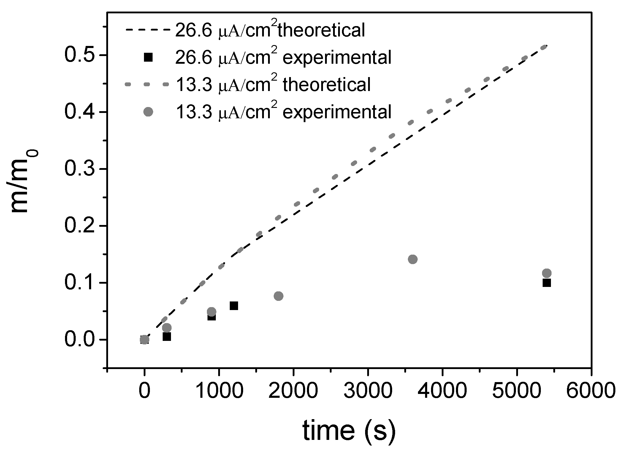
The characterization of the NiO seeds has been described previously elsewhere [13,23]. On the other hand, the NiO/Ni core-shell nanostructures were synthetized by inducing heteroprecipitation of Ni onto the NiO nanoplatelets suspension by reduction of the Ni(NO3)2·6H2O with hydrazine in basic medium under US and temperature control (50 °C) during 5 min. Figure 2a shows the overall size of NiO/Ni coreshell nanoparticles with a length diameter ranging 200–300 nm and a thickness around 30 nm. It is important to notice that the NiO nanoplatelets, which acts as core, retains their initial shape and size, while they supports the metallic Ni nanospheres with diameters of 15–30 nm (similar to the scheme of Figure 2b).
Additionally, the XRD analysis of Figure 2c confirmed the presence of the two crystallographic phases. On one side, the NiO peaks (200, 111 and 220) with a face-centered cubic lattice (Space group: Fm3m) with a unit cell dimension of 4.185 Å and a mean crystallite size of 28 nm. In addition, the metallic Ni peaks around 45° and 52.4° (111 and 200 respectively) according to the index card JCPDS No. 04-0850 and a face-centered cubic space group (Fm3m) with a unit cell dimension of 3.53 Å and a crystallite size of 14.5 nm.
Also, the N2 adsorption/desorption isotherms and the corresponding pore size distribution are given in Figure 2d. The curve exhibits the IV isotherms with an H3-type hysteresis loop (P/P0 > 0.4), indicative of the presence of mesopores. The specific surface area value of NiO/Ni was 16 m2/g. More than five times shorter than NiO seeds (BET SSA = 83.7m2/g). In addition, the resultant average pore size and pore volume obtained was 21.42 nm and 0.104 cm3/g respectively. The results suggest that the presence of metallic Ni onto the surfaces of NiO nanoplatelets decreases their pore size and their specific surface area. However, the final capacitance of the NiO/Ni coatings should be discussed also considering sharing of the electronic cloud when the metallic Ni is incrusted, since it could provide efficient electronic transport pathways during the charge-discharge process, which could benefit for the final electrochemical performance.

3.1. EPD Deposition

The manipulation of the nanoparticles modified in aqueous suspension was carried out at room conditions following the one-pot approach, and thus avoiding separation and/or drying of the nanoparticles before the coating process to impede their agglomeration.
In the free-PEI curve (Figure 3a), two zones of maximum stability are displayed far from the isoelectric point located at pH 10.5. At acid pH (2–3), zeta potential is closed to +30 mV. Between the pH range 11–12 the NiO/Ni zeta potential is negative and the adsorption of the cationic polyelectrolyte on the surface of the core-shell should be promoted. Because of this the adsorption of PEI was determined at pH 11.
Consequently, the exactly concentration of polyelectrolyte (PEI) required to fully cover the surface of the nanoplatelets was determined. In Figure 3b the zeta potential trend shows that as the polyelectrolyte addition increases, its adsorption reverses the surface charge up to achieve a maximum value which is indicative of the surface saturation. It is evident that a low amount of the PEI (2.5 wt %) is needed to completely revers the surface charge of the NiO/Ni nanoplatelets.
After PEI addition at pH 11, the variation of the zeta potential as a function of pH was measured again. Global charge balance at the particle surfaces was completely modified appearing positive sites in all pH range. Form zeta potential determination, cathodic deposition will be favored in EPD through a stable suspension by means of an electro-steric mechanism.
After the dispersion and stabilization of the NiO/Ni powder in the suspension, the EPD kinetics was determined under galvanostatic conditions applying the current densities mentioned in the experimental section. When the applied current density value was higher than 26.6 μA/cm2, the deposition of particles onto foils did not take place due to the electrode polarization. The absence of other ions/particles in suspension (which indicates a low carrier concentration) and the low dielectric constant of the solvent (low resistance) resulted in a low conductivity (<1 µS/cm). Figure 4 compares the theoretical (lines) and experimental (full symbols) kinetics curves as a result of the EPD processes only at 13.3 and 26.6 µA/cm2. The theoretical curves were calculated following Equations (5) and (6) and considering a sticking factor of 1 and starting conditions summarized in Table 1. Deposited mass was normalized (in percentages) to the initial mass of powder in the suspension. No significant differences were observed between the kinetics of deposition under tested conditions. However, a large difference can be appreciated between theoretical and experimental data which could be attributable to the degradation of the suspension during the deposition, in terms of electrophoretic mobility, conductivity and solid concentration [30].
Based on the studied kinetics and our previous experience, EPD conditions were chosen to obtain coatings of 1 mg. Figure 5 shows the micrographs at different magnifications of Ni foam fully coated by NiO/Ni core-shell particles after a thermal treatment of 325 °C and 60 min. The optimization of the work conditions for the suspension deposition resulted in a thin deposition yield. An open and interconnected porosity 100–500 μm is given by the foam substrate and a homogeneous and continuous film of the core-shell particles completely coats the complete surface of the foam. NiO/Ni particles ordering can be explained throughout the movement governed by the electro-hydrodynamics forces, when approach to the substrate surface and the binder role of PEI, which also reduces its ionized state forcing particles coagulation [31,32].

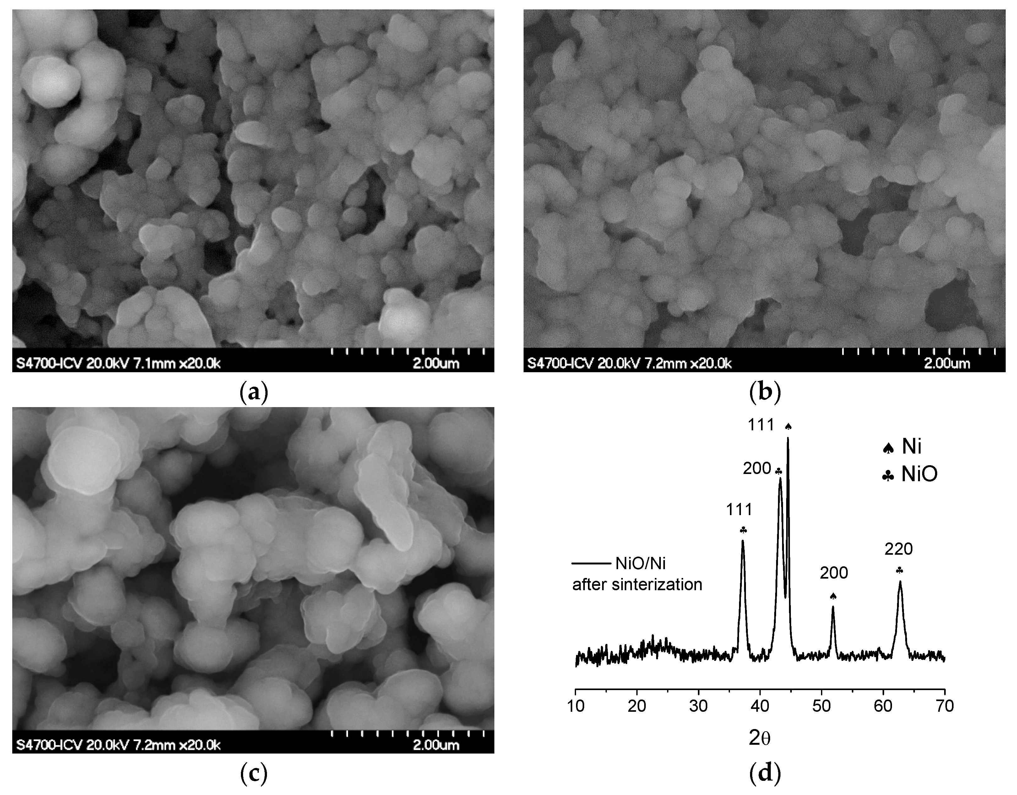
3.2. Sintering Study

The fabrication of electrodes with an open microstructure and well-defined ion diffusion and electron pathways maximizes the electrolyte contact with the surface of the electroactive material [28,33,34]. In order to determine the optimum heat treatment, because of its influence on the electrochemical properties, we studied three different thermal processes, described in the experimental section in Figure 2.
FESEM images in Figure 6a–c show the plate-like morphology after the different heat treatments. In the three cases, the level of consolidation is high and all particles are well-connected, however the achieved porosity was different either produced by the increase of temperature or by the time of the dwell of the thermal treatment. According to these micrographs, the effect of the increase of the temperature prevails over the effect of the time and therefore the most closed porosity is given by the heat treatment at high temperature, 375 °C, Figure 6b. An opener micro-architecture (with the foam macroporosity) could favor the electrolyte diffusion defining pathways and improving the electrolyte impregnation in the microstructure. More porosity means higher exposed specific surface to the electrolyte, thus the number of redox reactions, which take place at the interface electrode/electrolyte increase. In addition, the size of the connected particles of Figure 6c seems to be bigger that the size of the particle forming the microstructure in Figure 6a,b. The increase of the dwell time leads to the growth of the sintered grains of the microstructure reducing the mesoporosity within the nanoplatelets while increase macroporosity among them, which could affect to the electrochemical response.
In addition, different coatings were analyzed by XRD to confirm the presence of Ni and NiO crystallographic phases after the sintering process. Figure 6d shows the diffractogram of one of the analyzed samples (all samples presented similar patterns independently from the thermal treatment followed, not shown here). The spectra verify that during the heat treatment under inert atmosphere, the metallic Ni did not suffer oxidation or other phase transformation.

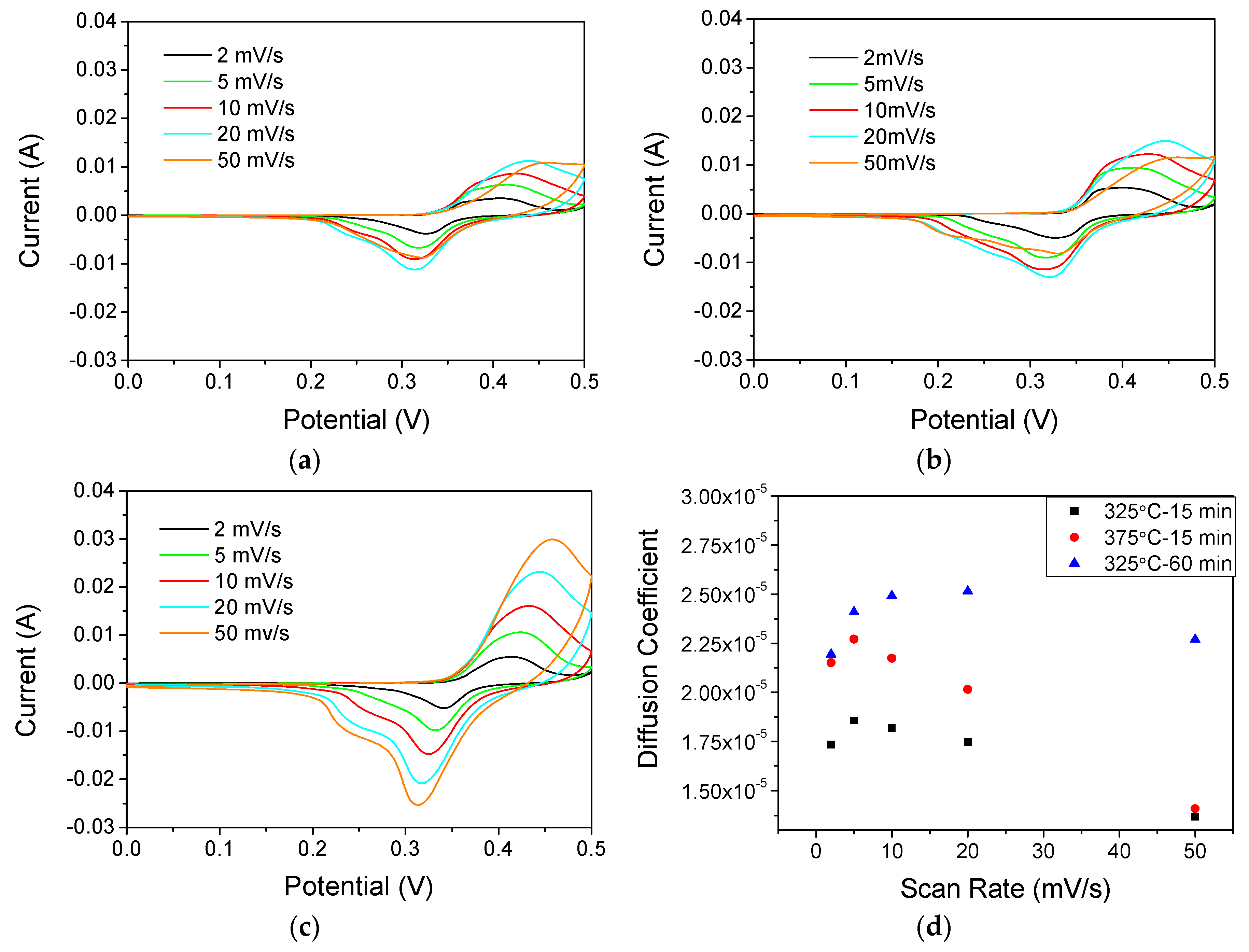
3.3. Electrochemical Response

In order to study the influence of the nickel metallic, the thermal treatment, and later consolidation in the final properties, the electrochemical performance of the sintered coatings were evaluated in terms of faradaic capacity. Figure 7 shows the cyclic voltammetry (CV) curves of NiO/Ni electrodes calcined at 325 °C-15 min (Figure 7a), 375 °C-15 min (Figure 7b) and 325 °C-60 min (Figure 7c) at a sweep rate of 10 mV/s. A pair of redox current peaks with symmetrical shape can be identified during the cathodic and anodic sweeps, indicating the pseudocapacitance behavior. They can be attributed to the following reversible redox reaction with a potential window of 0.120 V:
Ni + H2O ↔ NiO + 2H+ + 2e
It is well-known that the area under the curve in a cyclic voltagram is proportional to the specific capacitance and directly related with the specific surface area, where the redox reactions take place. In this study, the areas under the curves of Figure 7c were larger than the areas of Figure 7a,b which indicates that the thermal treatment most appropriated was 325 °C-60 min. These results can be discussed in accordance with the FESEM images of Figure 6 and the loading density of the electrodes. Although the size of the sintered grains is bigger and the nanoplatelets mesoporosity is lower (Figure 6c) the large macroporosity of the microstructure is the main responsible of the electrochemical response of this coating. However, also, the thin coating of Ni foams leads to a large active NiO/Ni surface at the electrode. In fact, the Ni foam has a specific surface of 300 m2/g and assuming that 0.1 g of foam is covered and tested, the 1 mg of NiO/Ni deposit results in a loading density in the order of 10−5 mg/cm2. Thus, after a thermal treatment of 325 °C-60 min, low loading densities and the increase of macroporosity results that the most of the NiO/Ni grains are active surfaces linked to the Ni foam.
To quantify the electrolyte diffusion through the microstructural pathways, the diffusion coefficients (D) were calculated by the Randles-Sevcik Equation (12).
i p = 268.6 × n 3 2 × A × D 1 2 × C × v 1 2
where ip is the current oxidation maximum in amperes, n is the number of electrons transferred in the redox reaction (2 e in our case, Equation (11)). A is electrode area in cm2, D is the diffusion coefficient in cm2/s, C is the electrolyte molar concentration and ν is scan rate in V/s.
Figure 7d shows the calculated values at different scan-rates. The coating sintered at 325 °C-60 min displays the highest diffusion coefficient values, which confirm our previous hypothesis.
In addition, specific capacitance values were also determined by galvanostatic measurements. Figure 8a presents the typical discharge voltage vs. time plots for NiO/Ni at current densities of 2 A/g in the potential range of 0–0.5 V, from which symmetric and quasi-linear shapes with well-defined plateaus during the discharge processes are observed, suggesting electrodes have pseudocapacitive behavior, which is in agreement with the result of above CV test.
The specific capacitance determined for the thermal treatment at 325 °C-60 min exhibits a specific capacitance of 755 F/g, which is better than the 363 F/g corresponding to the NiO seeds [13]. Other authors have been reported specific capacitance values within our range, such as 900 F/g for NiO/Pt electrodes [28], or far from our values, such as 2018 F/g for hydrothermal NiO coatings [35] or 157 F/g for NiO + Carbon by electrodeposition [36]. The density of the NiO/Ni electrode on Ni foams is generally low, limiting the volumetric performance. The density of the whole electrode can be considered that of the Ni foam (0.45 g/cm3) and, as the deposited NiO/Ni coatings are 1 mg in weight, the volumetric performance is 13 F/cm3. A capacitance retention of 62% was achieved after 1000 cycles. In spite of having a decrease of the specific capacitance, the value still being higher than the previous reported. The discharge profiles of the electrodes, parallel to the x-axis, confirmed also the typical pseudocapacitive contribution.

4. Conclusions

The obtained specific capacitance of NiO/Ni electrodes is 755 F/g, which is more than twice the results for simple NiO nanoplatelets used as electroactive material. This improvement of the electrochemical performance can be attributed to the presence of the metallic Ni nanoparticles in the nanostructure.
A thermal treatment of 325 °C-1 h leads a cohesive and consolidated NiO/Ni nanostructure well adhered to the Ni foam collector, with a macroporosity higher than 1 μm, which results in a high electrochemical performance, favoring the electrolyte diffusion and reaction throughout the porous structure, as well as the electronic conduction through the semiconductor nanostructure.
NiO/Ni core-shell nanostructures were synthesized by heterogeneous precipitation of metallic Ni over NiO nanoplateles seeds in aqueous suspensions. The stabilization of as-synthesized core-shell nanostructures and the optimization of the EPD parameters allow controlling nanoplatelets arrangement and the coating growth in 3D substrates. The Ni collector was fully and homogenously covered by only 1 mg of electroactive NiO/Ni free-binders materials.

Acknowledgments

The authors acknowledge the support of the projects MAT2015-70780-C4-1-P and the program MULTIMAT-CHALLENGE, reference S2013/MIT-2862.

Author Contributions

Begoña Ferrari and Zoilo Gonzalez conceived and designed the experiments. Joaquin Yus performed the experiments. Joaquin Yus, Begoña Ferrari, Antonio Javier Sanchez-Herencia and Zoilo Gonzalez analyzed the data and wrote the paper. Alvaro Caballero and Julian Morales contributed electrochemical equipments and also analyzed the data.

Conflicts of Interest

The authors declare no conflict of interest.

References

  1. Cuentas Gallegos, A.K.; Rincón, M.E. Carbon nanofiber and PEDOT-PSS bilayer systems as electrodes for symmetric and asymmetric electrochemical capacitor cells. J. Power Sources 2006, 162, 743–747. [Google Scholar] [CrossRef]
  2. Sidhu, N.K.; Rastogi, A.C. Electrochemical performance of supercapacitors based on carbon nanofoam composite and microporous poly(3,4-ethylenedioxythiophene) thin film asymmetric electrodes. Mater. Chem. Phys. 2016, 176, 75–86. [Google Scholar] [CrossRef]
  3. Xia, H.; Shirley Meng, Y.; Yuan, G.; Cui, C.; Lu, L. A symmetric RuO2/RuO2 supercapacitor operating at 1.6 V by using a neutral aqueous electrolyte. Electrochem. Solid State Lett. 2012, 15. [Google Scholar] [CrossRef]
  4. Yoo, C.Y.; Park, J.; Yun, D.S.; Yu, J.H.; Yoon, H.; Kim, J.N.; Yoon, H.C.; Kwak, M.; Kang, Y.C. Crucial role of a nickel substrate in Co3O4 pseudocapacitor directly grown on nickel and its electrochemical properties. J. Alloys Compd. 2016, 676, 407–413. [Google Scholar] [CrossRef]
  5. Argüello, J.A.; Cerpa, A.; Alanbari, M.H.; Fariñas, J.C.; Moreno, R. Preparation of manganese oxide-graphite electrodes by electrophoretic deposition. Ceram. Int. 2017, 43, 3231–3237. [Google Scholar] [CrossRef]
  6. Gonzalez, Z.; Ferrari, B.; Sanchez-Herencia, A.J.; Caballero, A.; Morales, J. Use of Polyelectrolytes for the Fabrication of Porous NiO Films by Electrophoretic Deposition for Supercapacitor Electrodes. Electrochim. Acta 2016, 211, 110–118. [Google Scholar] [CrossRef]
  7. Zhang, H.; Wang, X.; Chen, C.; An, C.; Xu, Y.; Dong, Y.; Zhang, Q.; Wang, Y.; Jiao, L.; Yuan, H. Facile synthesis of diverse transition metal oxide nanoparticles and electrochemical properties. Inorg. Chem. Front. 2016, 3, 1048–1057. [Google Scholar] [CrossRef]
  8. Yang, Z.; Xu, F.; Zhang, W.; Mei, Z.; Pei, B.; Zhu, X. Controllable preparation of multishelled NiO hollow nanospheres via layer-by-layer self-assembly for supercapacitor application. J. Power Sources 2014, 246, 24–31. [Google Scholar] [CrossRef]
  9. Bello, A.; Makgopa, K.; Fabiane, M.; Dodoo-Ahrin, D.; Ozoemena, K.I.; Manyala, N. Chemical adsorption of NiO nanostructures on nickel foam-graphene for supercapacitor applications. J. Mater. Sci. 2013, 48, 6707–6712. [Google Scholar] [CrossRef]
  10. Feng, F.; Zhao, S.; Liu, R.; Yang, Z.; Shen, Q. NiO Flowerlike porous hollow nanostructures with an enhanced interfacial storage capability for battery-to-pseudocapacitor transition. Electrochim. Acta 2016, 222, 1160–1168. [Google Scholar] [CrossRef]
  11. Zhang, Z.; Gao, Q.; Gao, H.; Shi, Z.; Wu, J.; Zhi, M.; Hong, Z. Nickel oxide aerogel for high performance supercapacitor electrodes. RSC Adv. 2016, 6. [Google Scholar] [CrossRef]
  12. Li, X.; Wang, L.; Shi, J.; Du, N.; He, G. Multishelled Nickel-Cobalt Oxide Hollow Microspheres with Optimized Compositions and Shell Porosity for High-Performance Pseudocapacitors. ACS Appl. Mater. Interfaces 2016, 8, 17276–17283. [Google Scholar] [CrossRef] [PubMed]
  13. Gonzalez, Z.; Ferrari, B.; Sanchez-Herencia, A.J.; Caballero, A.; Morales, J. Relevance of the Semiconductor Microstructure in the Pseudocapacitance of the Electrodes Fabricated by EPD of Binder-Free β-Ni(OH)2 Nanoplatelets. J. Electrochem. Soc. 2015, 162, D3001–D3012. [Google Scholar] [CrossRef]
  14. Kurra, N.; Alhebshi, N.A.; Alshareef, H.N. Microfabricated pseudocapacitors using Ni(OH)2 electrodes exhibit remarkable volumetric capacitance and energy density. Adv. Energy Mater. 2015, 5, 1–9. [Google Scholar] [CrossRef]
  15. Liu, X.Y.; Gao, Y.Q.; Yang, G.W. A flexible, transparent and super-long-life supercapacitor based on ultrafine Co3O4 nanocrystal electrodes. Nanoscale 2016, 8, 4227–4235. [Google Scholar] [CrossRef] [PubMed]
  16. Jiang, Y.Q.; Wang, P.B.; Zang, X.N.; Yang, Y.; Kozinda, A.; Lin, L. Uniformly Embedded Metal Oxide Nanoparticles in Vertically Aligned Carbon Nanotube Forests as Pseudocapacitor Electrodes for Enhanced Energy Storage. Nano Lett. 2013, 13, 3524–3530. [Google Scholar] [CrossRef] [PubMed]
  17. Żołek-Tryznowska, Z. Additives for Ink Manufacture. In Printing on Polymers; Izdebska, J., Thomas, S., Eds.; William Andrew Publishing: Norwich, NY, USA, 2016; pp. 57–66. [Google Scholar]
  18. McManus, D.; Vranic, S.; Withers, F.; Sanchez-Romaguera, V.; Macucci, M.; Yang, H.; Sorrentino, R.; Parvez, K.; Son, S.K.; Iannaccone, G.; et al. Water-based and biocompatible 2D crystal inks for all-inkjet-printed heterostructures. Nat. Nanotechnol. 2017, 12, 343–350. [Google Scholar] [CrossRef] [PubMed]
  19. Gonzalez, Z.; Yus, J.; Caballero, A.; Morales, J.; Sanchez-Herencia, A.J.; Ferrari, B. Electrochemical performance of pseudo-capacitor electrodes fabricated by Electrophoretic Deposition inducing Ni(OH)2 nanoplatelets agglomeration by Layer-by-Layer. Electrochim. Acta 2017, 247, 333–343. [Google Scholar] [CrossRef]
  20. Kazazi, M. Facile preparation of nanoflake-structured nickel oxide/carbon nanotube composite films by electrophoretic deposition as binder-free electrodes for high-performance pseudocapacitors. Curr. Appl. Phys. 2017, 17, 240–248. [Google Scholar] [CrossRef]
  21. Dios, M.; Gonzalez, Z.; Gordo, E.; Ferrari, B. Semiconductor-metal core-shell nanostructures by colloidal heterocoagulation in aqueous medium. Mater. Lett. 2016, 180, 327–331. [Google Scholar] [CrossRef]
  22. Wu, M.S.; Huang, C.Y.; Lin, K.H. Electrophoretic deposition of nickel oxide electrode for high-rate electrochemical capacitors. J. Power Sources 2009, 186, 557–564. [Google Scholar] [CrossRef]
  23. Zheng, Z.; Huang, B.; Qin, X.; Zhang, X.; Dai, Y.; Whangbo, M.-H. Facile in situ synthesis of visible-light plasmonic photocatalysts M@TiO2 (M = Au, Pt, Ag) and evaluation of their photocatalytic oxidation of benzene to phenol. J. Mater. Chem. 2011, 21, 9079. [Google Scholar] [CrossRef]
  24. Chen, X.; Mao, S.S. Titanium Dioxide Nanomaterials: Synthesis, Properties, Modifications, and Applications. Chem. Rev. 2007, 107, 2891–2959. [Google Scholar] [CrossRef] [PubMed]
  25. Wu, H.; Li, D.; Zhu, X.; Yang, C.; Liu, D.; Chen, X.; Song, Y.; Lu, L. High-performance and renewable supercapacitors based on TiO2 nanotube array electrodes treated by an electrochemical doping approach. Electrochim. Acta 2014, 116, 129–136. [Google Scholar] [CrossRef]
  26. Wen, W.; Wu, J.M. Eruption combustion synthesis of NiO/Ni nanocomposites with enhanced properties for dye-absorption and lithium storage. ACS Appl. Mater. Interfaces 2011, 3, 4112–4119. [Google Scholar] [CrossRef] [PubMed]
  27. Song, S.; Yao, S.; Cao, J.; Di, L.; Wu, G.; Guan, N.; Li, L. Heterostructured Ni/NiO composite as a robust catalyst for the hydrogenation of levulinic acid to γ-valerolactone. Appl. Catal. B Environ. 2017, 217, 115–124. [Google Scholar] [CrossRef]
  28. Lu, Q.; Lattanzi, M.W.; Chen, Y.P.; Kou, X.M.; Li, W.F.; Fan, X.; Unruh, K.M.; Chen, J.G.G.; Xiao, J.Q. Supercapacitor Electrodes with High-Energy and Power Densities Prepared from Monolithic NiO/Ni Nanocomposites. Angew. Chem. Int. Ed. 2011, 50, 6847–6850. [Google Scholar] [CrossRef] [PubMed]
  29. Dios, M.; Gonzalez, Z.; Gordo, E.; Ferrari, B. Chemical precipitation of nickel nanoparticles on Ti (C,N) suspensions focused on cermet processing. Int. J. Refract. Met. Hard Mater. 2017, 63, 2–8. [Google Scholar] [CrossRef]
  30. Ferrari, B.; Moreno, R. EPD kinetics: A review. J. Eur. Ceram. Soc. 2010, 30, 1069–1078. [Google Scholar] [CrossRef]
  31. Mishra, M.; Bhattacharjee, S.; Besra, L.; Sharma, H.S.; Uchikoshi, T.; Sakka, Y. Effect of pH localization on microstructure evolution of deposits during aqueous electrophoretic deposition (EPD). J. Eur. Ceram. Soc. 2010, 30, 2467–2473. [Google Scholar] [CrossRef]
  32. Besra, L.; Uchikoshi, T.; Suzuki, T.S.; Sakka, Y. Experimental verification of pH localization mechanism of particle consolidation at the electrode/solution interface and its application to pulsed DC electrophoretic deposition (EPD). J. Eur. Ceram. Soc. 2010, 30, 1187–1193. [Google Scholar] [CrossRef]
  33. Xu, P.; Miao, C.; Cheng, K.; Ye, K.; Yin, J.; Cao, D.; Wang, G.; Zhang, X. Preparation of binder-free porous ultrathin Ni(OH)2 nanoleafs using ZnO as pore forming agent displaying both high mass loading and excellent electrochemical energy storage performance. Electrochim. Acta 2016, 216, 499–509. [Google Scholar] [CrossRef]
  34. Yan, H.; Zhang, D.; Xu, J.; Lu, Y.; Liu, Y.; Qiu, K.; Zhang, Y. Solution growth of NiO nanosheets supported on Ni foam as high-performance electrodes for supercapacitors. Nano Res. Lett. 2014, 9, 424. [Google Scholar] [CrossRef] [PubMed]
  35. Lu, Z.; Chang, Z.; Liu, J.; Sun, X. Stable ultrahigh specific capacitance of NiO nanorod arrays. Nano Res. 2011, 4, 658–665. [Google Scholar] [CrossRef]
  36. Zhang, X.; Luo, J.; Tang, P.; Ye, X.; Peng, X.; Tang, H.; Sun, S.G.; Fransaer, J. A universal strategy for metal oxide anchored and binder-free carbon matrix electrode: A supercapacitor case with superior rate performance and high mass loading. Nano Energy 2017, 31, 311–321. [Google Scholar] [CrossRef]
Figure 1. Diagram of different thermal treatments employed for the optimization process.
Coatings 07 00193 g001
Figure 2. (a) FESEM images of the NiO-Ni powders; (b) scheme of the arrangement of NiO-Ni core-shell nanoparticles; (c) XRD patterns of the NiO-Ni powders after the synthesis process; and (d) N2 gas adsorption-desorption isotherms and pore size distribution of as-prepared NiO-Ni nanostructure.
Coatings 07 00193 g002
Figure 3. (a) Zeta potential vs pH curves for NiO-Ni nude nanoparticles and the stabilized with PEI; and (b) Zeta Potential of NiO-Ni nanoparticles as a function of the amount of added polyelectrolyte.
Coatings 07 00193 g003
Figure 4. Experimental approximation of the EPD kinetics for NiO-Ni suspensions deposited on a Ni foil substrate.
Coatings 07 00193 g004
Figure 5. Picture and Micrographs at different magnifications of a Nickel foam coated with NiO/Ni particles.
Coatings 07 00193 g005
Figure 6. Final morphology and porosity of the NiO-Ni coating after the different heat treatment: (a) 325 °C 15 min Ar, (b) 375 °C 15 min Ar, and (c) 325 °C 60 min Ar; (d) XRD patterns of the NiO-Ni powders after calcination and scraping from the substrates.
Coatings 07 00193 g006
Figure 7. Cyclic voltammetry of NiO-Ni deposits calcined at 325 °C-15 min (a), 375 °C-15 min (b) and 325 °C-60 min (c). Diffusion coefficient calculated by the Randles–Sevcik equation for the different heat treatments (d).
Coatings 07 00193 g007
Figure 8. Galvanostatic discharge curves at mA cm−2 of the different heat treatment electrodes (a); and its cyclic chronopotentiometric measurement (CP) (b).
Coatings 07 00193 g008
Table 1. EPD parameters.
Volume of Suspension, VElectrophoretic Mobility, μeDeposition Surface, SElectric Field, ESticking Factor, fCharacteristic Time, T
30 mL0.7186 × 10−4 cm2 V−1 s−13.75 cm215 V/cm17422 s

