
Graphene and Carbon Quantum Dot-Based Materials in Photovoltaic Devices: From Synthesis to Applications


Abstract
:
1. Introduction
- General synthetic approaches.
- Photonic properties.
- Graphene quantum dots in photovoltaic devices.
- Carbon quantum dots in photovoltaic devices.
- Outlook and perspectives.
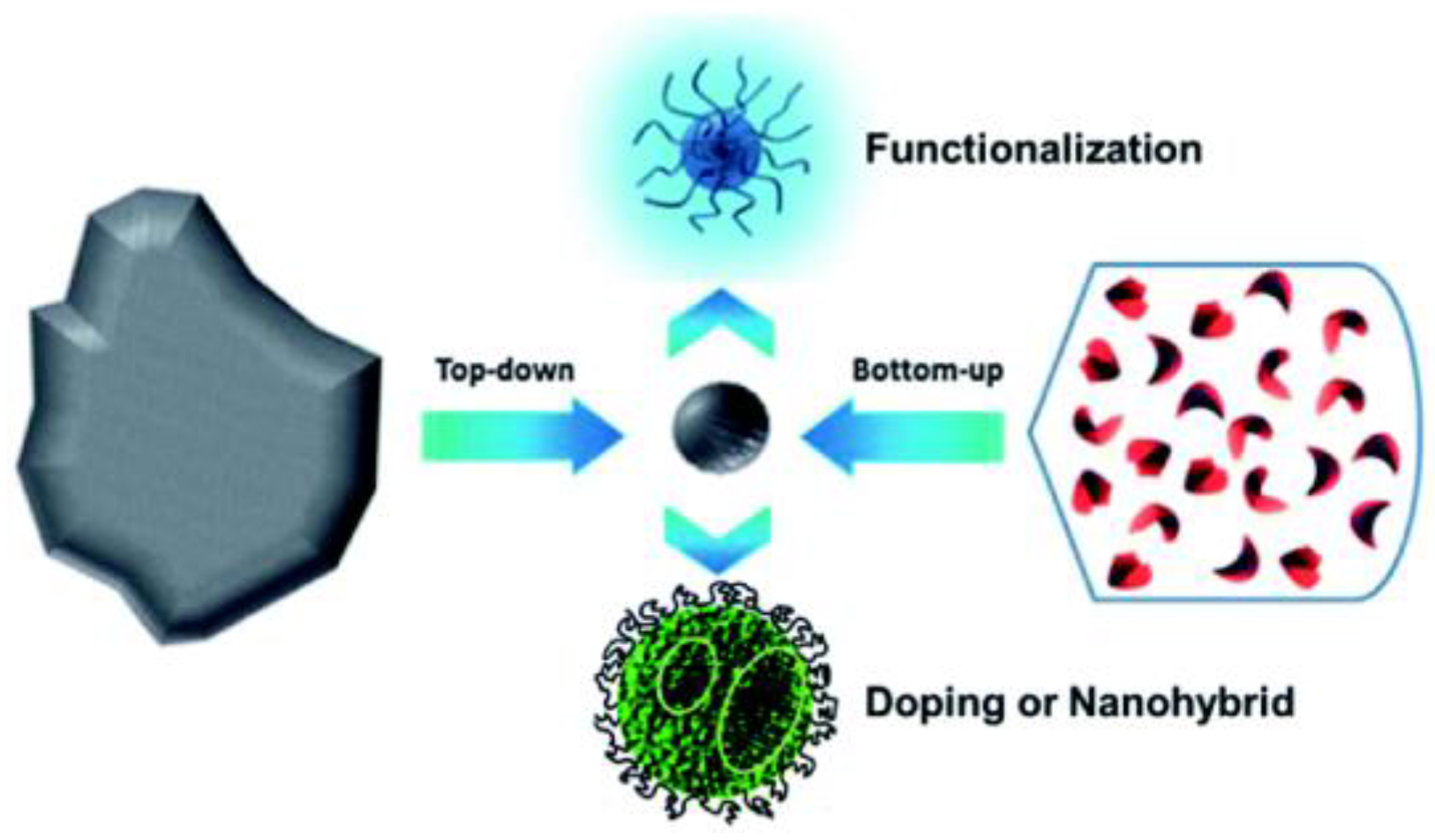
2. General Synthetic Approaches
2.1. Bottom-up Approach
2.1.1. Hydrothermal/Solvothermal Synthesis
2.1.2. Microwave Irradiation Synthesis
2.1.3. Soft Template Method
2.2. Top-down Approach
Electrochemical Methods
2.3. Acidic Oxidation or Chemical Ablation
3. Photonic Properties
3.1. Light Absorption
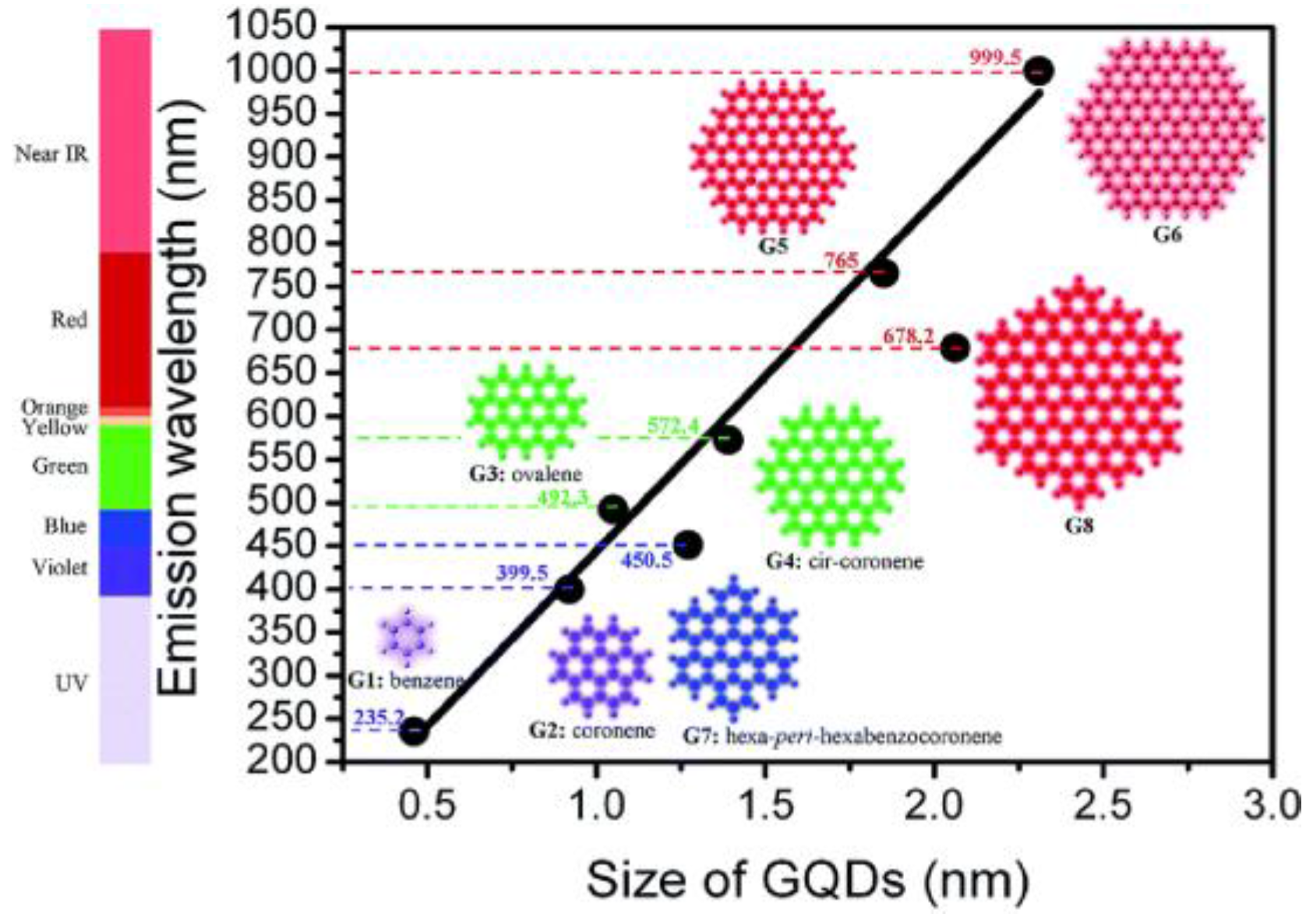
3.2. Light Emission
4. Graphene Quantum Dots in Photovoltaics
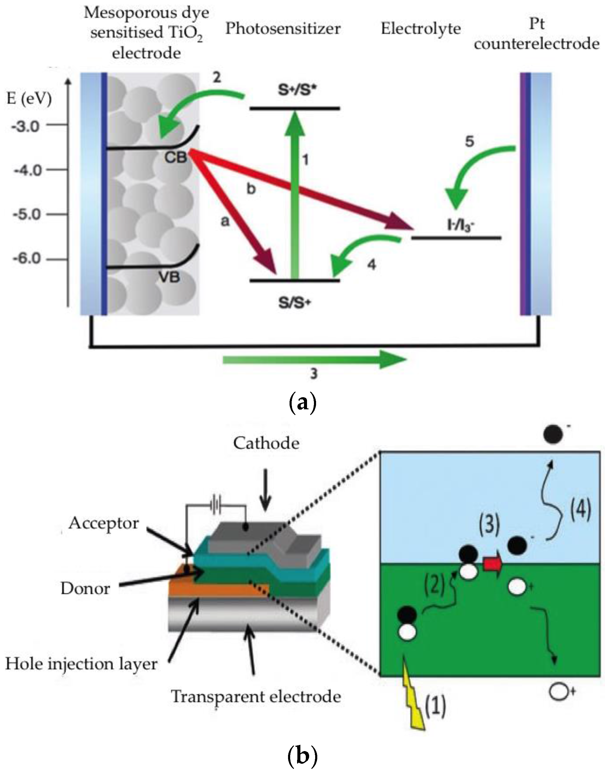
4.1. Light Harvesting
4.2. Counterelectrode
4.3. Hole Collector
4.4. Electron Collector
5. Carbon Dots in Photovoltaics
5.1. Light Harvesting
5.2. Counterelectrode
5.3. Hole Collection
5.4. Electron Collection
6. Outlook and Perspectives
Acknowledgments
Author Contributions
Conflicts of Interest
Abbreviations
| AFM | Atomic force microscope |
| AZO | Aluminum-doped zinc oxide |
| CDs | Carbon quantum dots |
| DSSC | Dye-sensitised solar cells |
| DR3TBDT | 3-ethyl rhodanine benzo[1,2-b:4,5-b′]dithiophene |
| ETL | Electron transport layer |
| GDs | Graphene dots |
| HTL | Hole transport layer |
| HRTEM | High resolution transmission electron microscopy |
| KH791 | (N-(2-aminoethyl)-3-aminopropyl)tris-(2-ethoxy) silane |
| N719 | Di-tetrabutylammonium cis-bis(isothiocyanato) bis (2,2′-bipyridyl -4,4′- dicarboxylato) ruthenium(II) |
| N3 | Cis-Bis(isothiocyanato) bis(2,2′-bipyridyl-4,4′-dicarboxylato ruthenium(II) |
| MWCNT | Multiwall carbon nanotubes |
| NCDs | Nitrogen-doped carbon dots |
| OSC | Organic solar cells |
| P3HT | Poly(3-hexyl thiophene) |
| PEDOT:PSS | Poly(3,4-ethylenedioxythiophene) polystyrene sulfonate |
| PCBM | [6,6]-phenyl-C61-butyric acid methyl ester |
| PffBT4T-2OD | Poly [(5,6-difluoro-2,1,3-benzothiadiazol-4,7-diyl)-alt-(3,3‴–di (2-octyldodecyl)-2, 2′; 5′, 2″; 5″, 2‴-quaterthiophen-5,5‴-diyl) |
| Ppy | Polypyrrol |
| PSC | Polymer solar cell |
| SMOPV | Small molecule organic photovoltaics |
| TC71BM | [6,6]-2-Thienyl-C71-butyric acid methyl ester |
| TPD | NN′-diphenyl-N-N′-bis(3-methylphenyl)-1,1′-biphenyl)-4,4′-diamine |
| Spiro-OMeTAD | N2,N2,N2′,N2′,N7,N7,N7′,N7′-octakis(4-methoxyphenyl)-9,9′-spiro bi[9H-fluorene]-2,2′,7,7′-tetramine |
References
- Armaroli, N.; Balzani, V. Solar Electricity and Solar Fuels: Status and Perspectives in the Context of the Energy Transition. Chem. A Eur. J. 2016, 22, 32–57. [Google Scholar] [CrossRef] [PubMed]
- Green, M.A.; Emery, K.; Hishikawa, Y.; Warta, W.; Dunlop, E.D. Solar cell efficiency tables (version 47). Prog. Photovolt. Res. Appl. 2016, 24, 3–11. [Google Scholar] [CrossRef]
- National Center for Photovoltaics. Available online: http://www.nrel.gov/ncpv/ (accessed on 23 August 2016).
- Albero, J.; Clifford, J.N.; Palomares, E. Quantum dot based molecular solar cells. Coord. Chem. Rev. 2014, 263–264, 53–64. [Google Scholar] [CrossRef]
- Medintz, I.L.; Uyeda, H.T.; Goldman, E.R.; Mattoussi, H. Quantum dot bioconjugates for imaging, labelling and sensing. Nat. Mater. 2005, 4, 435–446. [Google Scholar] [CrossRef] [PubMed]
- Nurmikko, A. What future for quantum dot-based light emitters? Nat. Nanotechnol. 2015, 10, 1001–1004. [Google Scholar] [CrossRef] [PubMed]
- Xu, X.; Ray, R.; Gu, Y.; Ploehn, H.J.; Gearheart, L.; Raker, K.; Scrivens, W.A. Electrophoretic analysis and purification of fluorescent single-walled carbon nanotube fragments. J. Am. Chem. Soc. 2004, 126, 12736–12737. [Google Scholar] [CrossRef] [PubMed]
- Sun, Y.P.; Zhou, B.; Lin, Y.; Wang, W.; Fernando, K.A.S.; Pathak, P.; Meziani, M.J.; Harruff, B.A.; Wang, X.; Wang, H.; et al. Quantum-sized carbon dots for bright and colorful photoluminescence. J. Am. Chem. Soc. 2006, 128, 7756–7757. [Google Scholar] [CrossRef] [PubMed]
- Novoselov, K.S.; Geim, A.K.; Morozov, S.V.; Jiang, D.; Zhang, Y.; Dubonos, S.V.; Grigorieva, I.V.; Firsov, A.A. Electric Field Effect in Atomically Thin Carbon Films. Science 2011, 306, 666–669. [Google Scholar] [CrossRef] [PubMed]
- Ding, C.; Zhu, A.; Tian, Y. Functional surface engineering of C-dots for fluorescent biosensing and in vivo bioimaging. Acc. Chem. Res. 2014, 47, 20–30. [Google Scholar] [CrossRef] [PubMed]
- Li, H.; Kang, Z.; Liu, Y.; Lee, S.-T. Carbon nanodots: Synthesis, properties and applications. J. Mater. Chem. 2012, 22, 24230–24253. [Google Scholar] [CrossRef]
- Zheng, X.T.; Ananthanarayanan, A.; Luo, K.Q.; Chen, P. Glowing graphene quantum dots and carbon dots: Properties, syntheses, and biological applications. Small 2015, 11, 1620–1636. [Google Scholar] [CrossRef] [PubMed]
- Baker, S.N.; Baker, G.A. Luminescent carbon nanodots: Emergent nanolights. Angew. Chem. Int. Ed. 2010, 49, 6726–6744. [Google Scholar] [CrossRef] [PubMed]
- Shen, J.; Zhu, Y.; Yang, X.; Li, C. Graphene quantum dots: Emergent nanolights for bioimaging, sensors, catalysis and photovoltaic devices. Chem. Commun. 2012, 48, 3686–3699. [Google Scholar] [CrossRef] [PubMed]
- Ding, H.; Yu, S.-B.; Wei, J.-S.; Xiong, H.-M. Full-Color Light-Emitting Carbon Dots with a Surface-State-Controlled Luminescence Mechanism. ACS Nano 2015, 10, 484–491. [Google Scholar] [CrossRef] [PubMed]
- Wang, Y.; Hu, A. Carbon quantum dots: Synthesis, properties and applications. J. Mater. Chem. C 2014, 2, 6921–6939. [Google Scholar] [CrossRef]
- Li, X.M.; Rui, M.C.; Song, J.Z.; Shen, Z.H.; Zeng, H.B.; Li, X.M.; Rui, M.C.; Song, J.Z.; Shen, Z.H.; Zeng, H.B. Carbon and Graphene Quantum Dots for Optoelectronic and Energy Devices: A Review. Adv. Funct. Mater. 2015, 25, 4929–4947. [Google Scholar] [CrossRef]
- Zhang, Z.; Zhang, J.; Chen, N.; Qu, L. Graphene quantum dots: An emerging material for energy-related applications and beyond. Energy Environ. Sci. 2012, 5, 8869–8890. [Google Scholar] [CrossRef]
- Miao, P.; Han, K.; Tang, Y.; Wang, B.; Lin, T.; Cheng, W. Recent advances in carbon nanodots: Synthesis, properties and biomedical applications. Nanoscale 2015, 7, 1586–1595. [Google Scholar] [CrossRef] [PubMed]
- Fan, Z.; Li, S.; Yuan, F.; Fan, L. Fluorescent graphene quantum dots for biosensing and bioimaging. RSC Adv. 2015, 5, 19773–19789. [Google Scholar] [CrossRef]
- Van Pham, C.; Madsuha, A.F.; Nguyen, T.V.; Krueger, M. Graphene-quantum dot hybrid materials on the road to optoelectronic applications. Synth. Met. 2016, 219, 33–43. [Google Scholar] [CrossRef]
- Mirtchev, P.; Henderson, E.J.; Soheilnia, N.; Yip, C.M.; Ozin, G.A. Solution phase synthesis of carbon quantum dots as sensitizers for nanocrystalline TiO2 solar cells. J. Mater. Chem. 2012, 22, 1265–1269. [Google Scholar] [CrossRef]
- Zhang, H.; Zhang, Q.; Li, M.; Kan, B.; Ni, W.; Wang, Y.; Yang, X.; Du, C.; Bc, X.W.; Chen, Y. Investigation of the enhanced performance and lifetime of organic solar cells using solution-processed carbon dots as the electron transport layers. J. Mater. Chem. C 2015, 3, 12403–12409. [Google Scholar] [CrossRef]
- Zhang, Y.-Q.; Ma, D.-K.; Zhuang, Y.; Zhang, X.; Chen, W.; Hong, L.-L.; Yan, Q.-X.; Yu, K.; Huang, S.-M. One-pot synthesis of N-doped carbon dots with tunable luminescence properties. J. Mater. Chem. 2012, 22, 16714–16718. [Google Scholar] [CrossRef]
- Zhang, Y.Q.; Ma, D.K.; Zhang, Y.G.; Chen, W.; Huang, S.M. N-doped carbon quantum dots for TiO2-based photocatalysts and dye-sensitized solar cells. Nano Energy 2013, 2, 545–552. [Google Scholar] [CrossRef]
- Liu, C.; Chang, K.; Guo, W.; Li, H.; Shen, L.; Chen, W.; Yan, D. Improving charge transport property and energy transfer with carbon quantum dots in inverted polymer solar cells. Appl. Phys. Lett. 2014, 105, 073306. [Google Scholar] [CrossRef]
- Dao, V.D.; Kim, P.; Baek, S.; Larina, L.L.; Yong, K.; Ryoo, R.; Ko, S.H.; Choi, H.S. Facile synthesis of carbon dot-Au nanoraspberries and their application as high-performance counter electrodes in quantum dot-sensitized solar cells. Carbon 2016, 96, 139–144. [Google Scholar] [CrossRef]
- Sun, M.; Ma, X.; Chen, X.; Sun, Y.; Cui, X.; Lin, Y. A nanocomposite of carbon quantum dots and TiO2 nanotube arrays: Enhancing photoelectrochemical and photocatalytic properties. RSC Adv. 2014, 4, 1120–1127. [Google Scholar] [CrossRef]
- Briscoe, J.; Marinovic, A.; Sevilla, M.; Dunn, S.; Titirici, M. Biomass-Derived Carbon Quantum Dot Sensitizers for Solid-State Nanostructured Solar Cells. Angew. Chem. Int. Ed. 2015, 54, 4463–4468. [Google Scholar] [CrossRef] [PubMed]
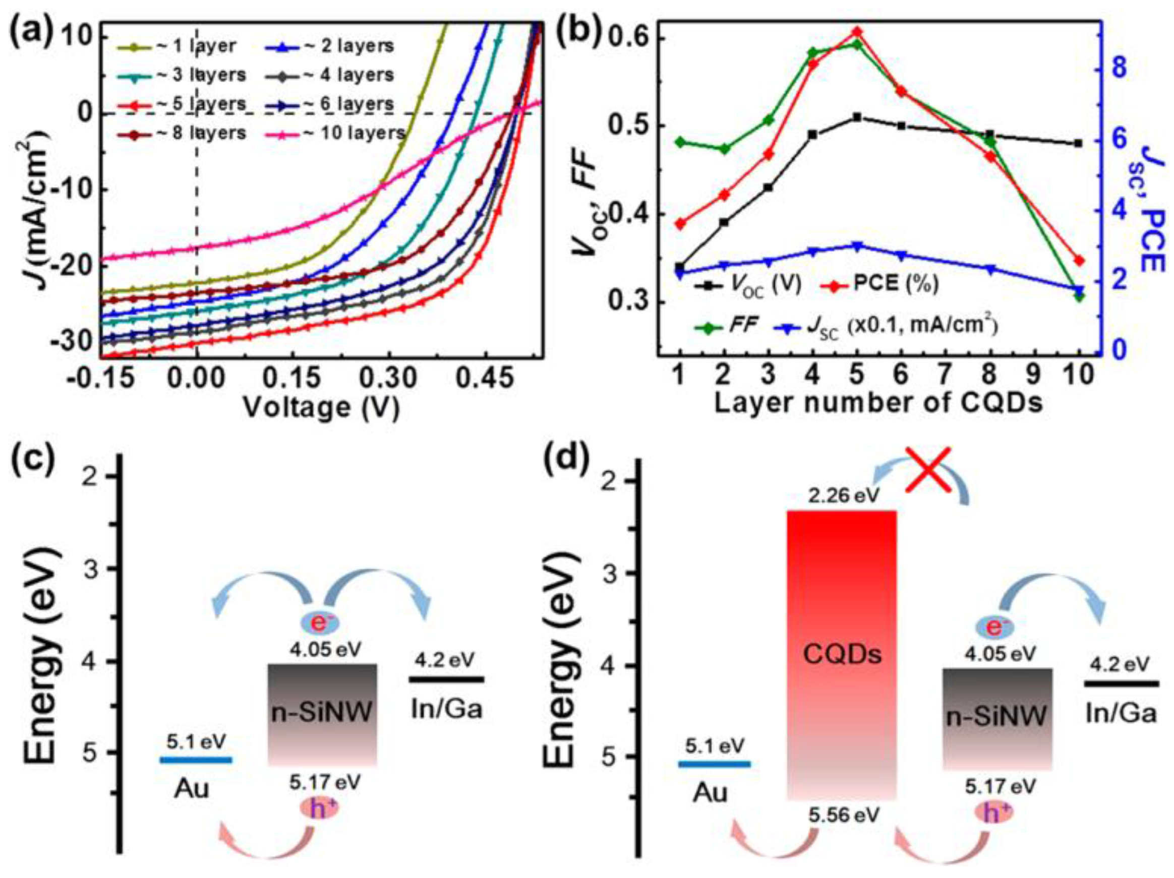
- Xie, C.; Nie, B.; Zeng, L.; Liang, F.X.; Wang, M.Z.; Luo, L.; Feng, M.; Yu, Y.; Wu, C.Y.; Wu, Y.; et al. Core-shell heterojunction of silicon nanowire arrays and carbon quantum dots for photovoltaic devices and self-driven photodetectors. ACS Nano 2014, 8, 4015–4022. [Google Scholar] [CrossRef] [PubMed]
- Huang, J.J.; Zhong, Z.F.; Rong, M.Z.; Zhou, X.; Chen, X.D.; Zhang, M.Q. An easy approach of preparing strongly luminescent carbon dots and their polymer based composites for enhancing solar cell efficiency. Carbon 2014, 70, 190–198. [Google Scholar] [CrossRef]
- Kwon, W.; Lee, G.; Do, S.; Joo, T.; Rhee, S.W. Size-controlled soft-template synthesis of carbon nanodots toward versatile photoactive materials. Small 2014, 10, 506–513. [Google Scholar] [CrossRef] [PubMed]
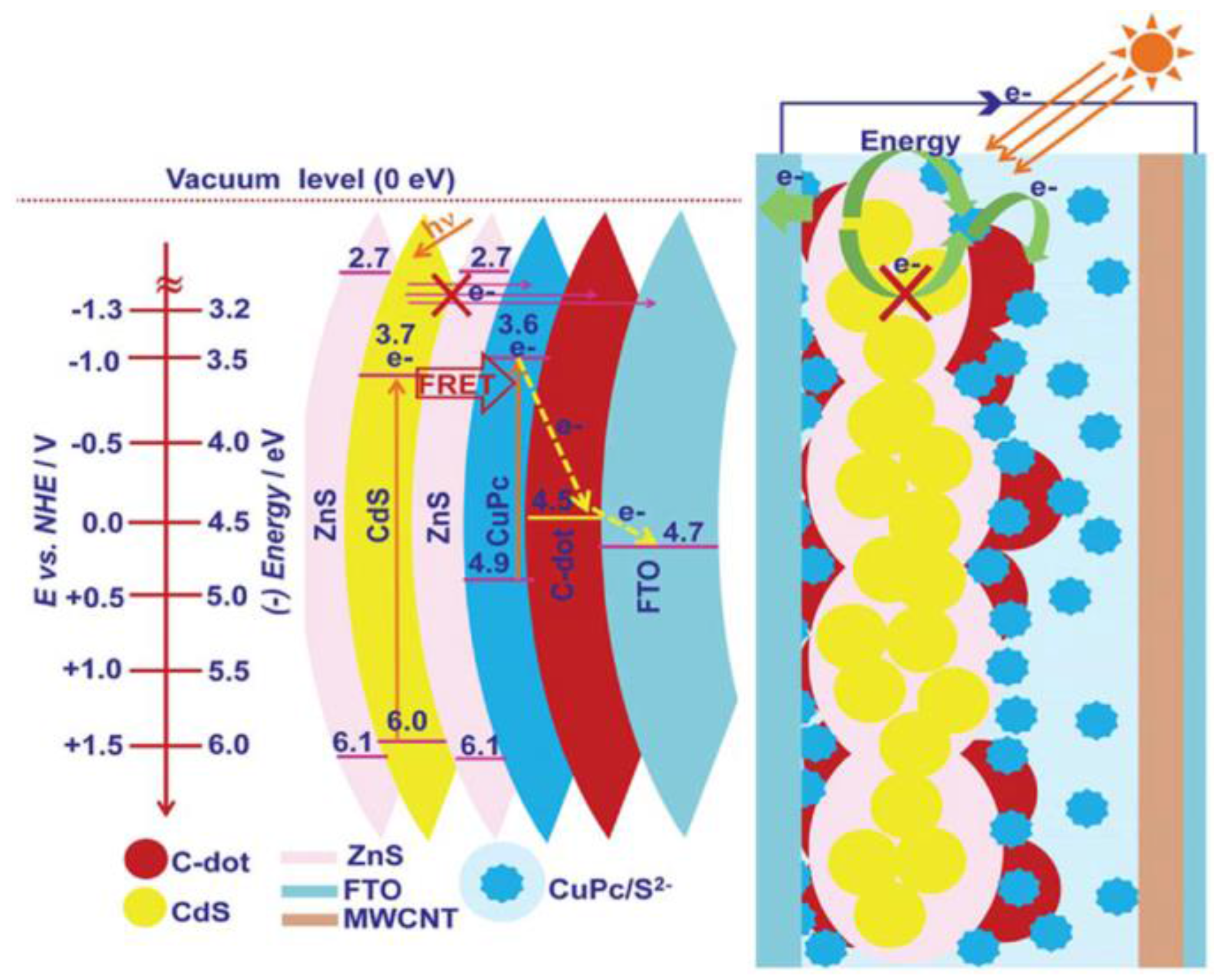
- Narayanan, R.; Deepa, M.; Srivastava, A.K. Forster resonance energy transfer and carbon dots enhance light harvesting in a solid-state quantum dot solar cell. J. Mater. Chem. A 2013, 1, 3907–3918. [Google Scholar] [CrossRef]
- Ma, Z.; Zhang, Y.L.; Wang, L.; Ming, H.; Li, H.; Zhang, X.; Wang, F.; Liu, Y.; Kang, Z.; Lee, S.T. Bioinspired photoelectric conversion system based on carbon-quantum-dot- doped dye-semiconductor complex. ACS Appl. Mater. Interfaces 2013, 5, 5080–5084. [Google Scholar] [CrossRef] [PubMed]
- Paulo, S.; Stoica, G.; Cambarau, W.; Martinez-Ferrero, E.; Palomares, E. Carbon quantum dots as new hole transport material for perovskite solar cells. Synth. Met. 2016. [Google Scholar] [CrossRef]
- Yan, X.; Cui, X.; Li, B.; Li, L.S. Large, solution-processable graphene quantum dots as light absorbers for photovoltaics. Nano Lett. 2010, 10, 1869–1873. [Google Scholar] [CrossRef] [PubMed]
- Tsai, M.-L.; Tu, W.-C.; Tang, L.; Wei, T.-C.; Wei, W.-R.; Lau, S.P.; Chen, L.-J.; He, J.-H. Efficiency Enhancement of Silicon Heterojunction Solar Cells via Photon Management Using Graphene Quantum Dot as Downconverters. Nano Lett. 2016, 16, 309–313. [Google Scholar] [CrossRef] [PubMed]
- Zhu, Z.; Ma, J.; Wang, Z.; Mu, C.; Fan, Z.; Du, L.; Bai, Y.; Fan, L.; Yan, H.; Phillips, D.L.; et al. Efficiency enhancement of perovskite solar cells through fast electron extraction: The role of graphene quantum dots. J. Am. Chem. Soc. 2014, 136, 3760–3763. [Google Scholar] [CrossRef] [PubMed]
- Li, Y.; Hu, Y.; Zhao, Y.; Shi, G.; Deng, L.; Hou, Y.; Qu, L. An electrochemical avenue to green-luminescent graphene quantum dots as potential electron-acceptors for photovoltaics. Adv. Mater. 2011, 23, 776–780. [Google Scholar] [CrossRef] [PubMed]
- Dutta, M.; Sarkar, S.; Ghosh, T.; Basak, D. ZnO/graphene quantum dot solid-state solar cell. J. Phys. Chem. C 2012, 116, 20127–20131. [Google Scholar] [CrossRef]
- Tsai, M.-L.; Wei, W.-R.; Tang, L.; Chang, H.-C.; Tai, S.-H.; Yang, P.-K.; Lau, S.P.; Chen, L.-J.; He, J.-H. 13% Efficiency Si Hybrid Solar Cells via Concurrent Improvement in Optical and Electrical Properties by Employing Graphene Quantum Dots. ACS Nano 2016, 10, 815–821. [Google Scholar] [CrossRef] [PubMed]
- Gao, P.; Ding, K.; Wang, Y.; Ruan, K.; Diao, S.; Zhang, Q.; Sun, B.; Jie, J. Crystalline Si/graphene quantum dots heterojunction solar cells. J. Phys. Chem. C 2014, 118, 5164–5171. [Google Scholar] [CrossRef]
- Pan, D.; Zhang, J.; Li, Z.; Wu, M. Hydrothermal route for cutting graphene sheets into blue-luminescent graphene quantum dots. Adv. Mater. 2010, 22, 734–738. [Google Scholar] [CrossRef] [PubMed]
- Chen, L.; Guo, C.X.; Zhang, Q.; Lei, Y.; Xie, J.; Ee, S.; Guai, G.; Song, Q.; Li, C.M. Graphene quantum-dot-doped polypyrrole counter electrode for high-performance dye-sensitized solar cells. ACS Appl. Mater. Interfaces 2013, 5, 2047–2052. [Google Scholar] [CrossRef] [PubMed]
- Kim, J.K.; Park, M.J.; Kim, S.J.; Wang, D.H.; Cho, S.P.; Bae, S.; Park, J.H.; Hong, B.H. Balancing light absorptivity and carrier conductivity of graphene quantum dots for high-efficiency bulk heterojunction solar cells. ACS Nano 2013, 7, 7207–7212. [Google Scholar] [CrossRef] [PubMed]
- Gupta, V.; Chaudhary, N.; Srivastava, R.; Sharma, G.D.; Bhardwaj, R.; Chand, S. Luminscent graphene quantum dots for organic photovoltaic devices. J. Am. Chem. Soc. 2011, 133, 9960–9963. [Google Scholar] [CrossRef] [PubMed]
- Fang, X.; Li, M.; Guo, K.; Li, J.; Pan, M.; Bai, L.; Luoshan, M.; Zhao, X. Graphene quantum dots optimization of dye-sensitized solar cells. Electrochim. Acta 2014, 137, 634–638. [Google Scholar] [CrossRef]
- Mihalache, I.; Radoi, A.; Mihaila, M.; Munteanu, C.; Marin, A.; Danila, M.; Kusko, M.; Kusko, C. Charge and energy transfer interplay in hybrid sensitized solar cells mediated by graphene quantum dots. Electrochim. Acta 2015, 153, 306–315. [Google Scholar] [CrossRef]
- Peng, J.; Gao, W.; Gupta, B.K.; Liu, Z.; Romero-Aburto, R.; Ge, L.; Song, L.; Alemany, L.B.; Zhan, X.; Gao, G.; et al. Graphene quantum dots derived from carbon fibers. Nano Lett. 2012, 12, 844–849. [Google Scholar] [CrossRef] [PubMed]
- Li, M.; Ni, W.; Kan, B.; Wan, X.; Zhang, L.; Zhang, Q.; Long, G.; Zuo, Y.; Chen, Y. Graphene quantum dots as the hole transport layer material for high-performance organic solar cells. Phys. Chem. Chem. Phys. 2013, 15, 18973–18978. [Google Scholar] [CrossRef] [PubMed]
- Li, L.; Wu, G.; Yang, G.; Peng, J.; Zhao, J.; Zhu, J.-J. Focusing on luminescent graphene quantum dots: Current status and future perspectives. Nanoscale 2013, 5, 4015–4039. [Google Scholar] [CrossRef] [PubMed]
- Low, C.T.J.; Walsh, F.C.; Chakrabarti, M.H.; Hashim, M.A.; Hussain, M.A. Electrochemical approaches to the production of graphene flakes and their potential applications. Carbon 2013, 54, 1–21. [Google Scholar] [CrossRef]
- Zhang, M.; Bai, L.; Shang, W.; Xie, W.; Ma, H.; Fu, Y.; Fang, D.; Sun, H.; Fan, L.; Han, M.; et al. Facile synthesis of water-soluble, highly fluorescent graphene quantum dots as a robust biological label for stem cells. J. Mater. Chem. 2012, 22, 7461–7467. [Google Scholar] [CrossRef]
- Sk, M.A.; Ananthanarayanan, A.; Huang, L.; Lim, K.H.; Chen, P. Revealing the tunable photoluminescence properties of graphene quantum dots. J. Mater. Chem. C 2014, 2, 6954–6960. [Google Scholar] [CrossRef]
- Song, Y.; Zhu, S.; Yang, B. Bioimaging based on fluorescent carbon dots. RSC Adv. 2014, 4, 27184–27200. [Google Scholar] [CrossRef]
- Gan, Z.; Xiong, S.; Wu, X.; Xu, T.; Zhu, X.; Gan, X.; Guo, J.; Shen, J.; Sun, L.; Chu, P.K. Mechanism of photoluminescence from chemically derived graphene oxide: Role of chemical reduction. Adv. Opt. Mater. 2013, 1, 926–932. [Google Scholar] [CrossRef]
- Hong, G.; Diao, S.; Antaris, A.L.; Dai, H. Carbon Nanomaterials for Biological Imaging and Nanomedicinal Therapy. Chem. Rev. 2015, 115, 10816–10906. [Google Scholar] [CrossRef] [PubMed]
- Gan, Z.; Xu, H.; Hao, Y. Mechanism for excitation-dependent photoluminescence from graphene quantum dots and other graphene oxide derivates: Consensus, debates and challenges. Nanoscale 2016, 7794–7807. [Google Scholar] [CrossRef] [PubMed]
- Ritter, K.A.; Lyding, J.W. The influence of edge structure on the electronic properties of graphene quantum dots and nanoribbons. Nat. Mater. 2009, 8, 235–242. [Google Scholar] [CrossRef] [PubMed]
- Xie, C.; Zhang, X.; Wu, Y.; Zhang, X.; Zhang, X.; Wang, Y.; Zhang, W.; Gao, P.; Han, Y.; Jie, J. Surface passivation and band engineering: A way toward high efficiency graphene-planar Si solar cells. J. Mater. Chem. A 2013, 1, 8567–8574. [Google Scholar] [CrossRef]
- Clifford, J.N.; Martínez-Ferrero, E.; Viterisi, A.; Palomares, E. Sensitizer molecular structure-device efficiency relationship in dye sensitized solar cells. Chem. Soc. Rev. 2011, 40, 1635–1646. [Google Scholar] [CrossRef] [PubMed]
- O’Regan, B.; Gratzel, M. A low-cost, high-efficiency solar cell based on dye-sensitized colloidal TiO2 films. Nature 1991, 353, 737–740. [Google Scholar] [CrossRef]
- Mathew, S.; Yella, A.; Gao, P.; Humphry-Baker, R.; Curchod, B.F.E.; Ashari-Astani, N.; Tavernelli, I.; Rothlisberger, U.; Khaja, N.; Grätzel, M. Dye-sensitized solar cells with 13% efficiency achieved through the molecular engineering of porphyrin sensitizers. Nat. Chem. 2014, 6, 242–247. [Google Scholar] [CrossRef] [PubMed]
- Weickert, J.; Dunbar, R.B.; Hesse, H.C.; Wiedemann, W.; Schmidt-Mende, L. Nanostructured organic and hybrid solar cells. Adv. Mater. 2011, 23, 1810–1828. [Google Scholar] [CrossRef] [PubMed]
- Brabec, C.J.; Heeney, M.; McCulloch, I.; Nelson, J. Influence of blend microstructure on bulk heterojunction organic photovoltaic performance. Chem. Soc. Rev. 2011, 40, 1185–1199. [Google Scholar] [CrossRef] [PubMed] [Green Version]
- Lu, L.; Zheng, T.; Wu, Q.; Schneider, A.M.; Zhao, D.; Yu, L. Recent Advances in Bulk Heterojunction Polymer Solar Cells. Chem. Rev. 2015, 115, 12666–12731. [Google Scholar] [CrossRef] [PubMed]
- Liu, Y.; Zhao, J.; Li, Z.; Mu, C.; Ma, W.; Hu, H.; Jiang, K.; Lin, H.; Ade, H.; Yan, H. Aggregation and morphology control enables multiple cases of high-efficiency polymer solar cells. Nat. Commun. 2014, 5, 5293. [Google Scholar] [CrossRef] [PubMed]
- Zhao, J.; Li, Y.; Yang, G.; Jiang, K.; Lin, H.; Ade, H.; Ma, W.; Yan, H. Efficient organic solar cells processed from hydrocarbon solvents. Nat. Energy 2016, 1, 15027. [Google Scholar] [CrossRef]
- Zhao, W.; Qian, D.; Zhang, S.; Li, S.; Inganäs, O.; Gao, F.; Hou, J. Fullerene-Free Polymer Solar Cells with over 11% Efficiency and Excellent Thermal Stability. Adv. Mater. 2016, 28, 4737–4739. [Google Scholar] [CrossRef] [PubMed]
- Wang, H.; Hu, Y.H. Graphene as a counter electrode material for dye-sensitized solar cells. Energy Environ. Sci. 2012, 5, 8182–8188. [Google Scholar] [CrossRef]
- Yang, W.S.; Noh, J.H.; Jeon, N.J.; Kim, Y.C.; Ryu, S.; Seo, J.; Seok, S., II. High-performance photovoltaic perovskite layers fabricated through intramolecular exchange. Science 2015, 348, 1234–1237. [Google Scholar] [CrossRef] [PubMed]
- Williams, K.J.; Nelson, C.A.; Yan, X.; Li, L.-S.; Zhu, X. Hot Electron Injection from Graphene Quantum Dots to TiO2. ACS Nano 2013, 7, 1388–1394. [Google Scholar] [CrossRef] [PubMed]


| Synthesis 1 | Carbon Source | Average Size (nm) | Surface Groups | Solar Cell 2 | Jsc (mA/cm2) | Voc (V) | FF (%) | η (%) | Effect | R 3 |
|---|---|---|---|---|---|---|---|---|---|---|
| H | γ-butyrolactone | 9 ± 6 | Sulfonate, carboxyl, hydroxyl, alkyl | DSSC | 0.53 | 0.38 | 64 | 0.13 | Emissive traps on the dot surface and enhancement of recombination | [22] |
| H | Citric acid | 1–2 | carboxyl | SMOPV | 13.32 | 0.904 | 63.7 | 7.67 | Increment in exciton separation and charge collection | [23] |
| PSC | 9.98 | 0.609 | 54.8 | 3.42 | ||||||
| H | CCl4 | 1.5–3.3 | Amino, carboxylic | DSSC | 0.33 | 0.370 | 43 | 0.13 | Contribution to light absorption | [24,25] |
| H | Polystyrene-co-maleic anhydride | --- | --- | PSC | 13.61 | 0.870 | 59.5 | 7.05 | Improvement of absorption in the UV and charge transport | [26] |
| M | Citric acid | 200 4 | Carboxylic, primary amines | QDSC | 16.6 4 | 0.708 4 | 46 4 | 5.4 4 | Improved charge extraction | [27] |
| 1.2 5 | 2.0 5 | 0.550 5 | 16 5 | 0.18 5 | ||||||
| E | Graphite rods | <4 | Hydroxyl, carboxyl, aromatic groups, epoxide/ether | DSSC | 0.02 | 0.580 | 35 | 0.0041 | Non-optimized electrolyte and electrode | [28] |
| H | Biomass (chitin, chitosan, glucose) | 14.1 ± 2.4 chitin 8.1 ± 0.3 chitosan 2.57 ± 0.04 glucose | Amine, amide, hydroxyl | DSSC | 0.674 6 | 0.265 6 | 43 6 | 0.077 6 | Influence of surface groups | [29] |
| E | Graphite rod | 4.5 | --- | Si | 30.09 | 0.510 | 59.3 | 9.1 | Improvement of absorption in the UV and decrease of recombination | [30] |
| H | Ascorbic acid | 3–4 | Carboxylic, hydroxyl | DSSC | 8.40 | 0.610 | 62 | 3.18 | Improvement of light absorption | [31] |
| S | Citric acid | 1.5 | Aldehyde, carboxylic | PSC | 0.288 | 1.588 | 48.5 | 0.23 | Insulating character of oleylamine ligand | [32] |
| H | Glucose | 16 | --- | QDSC | 1.88 | 0.605 | 31 | 0.35 | Increment of charge transfer and decrease of recombination | [33] |
| E | Graphite rods | <10 | --- | DSSC | 0.64 | 0.500 | -- | 0.147 | Improvement of absorption in the UV and decrease of recombination | [34] |
| H | Citric acid | 2–3 | --- | PerSC | 7.83 | 0.515 | 74 | 3.00 | Non-optimized device | [35] |
| Synthesis 1 | Carbon Source | Size (nm) | Surface Groups | Solar Cell 2 | Jsc (mA/cm2) | Voc (V) | FF (%) | η (%) | Effect | R3 |
|---|---|---|---|---|---|---|---|---|---|---|
| H | Bromobenzoic acid | 13.5 | 1,3,5 trialkyl phenyl | DSSC | 0.2 | 0.48 | 58 | 0.055 | Poor charge injection due to low affinity of GDs to titania | [36] |
| M | Glucose | 3.4 | --- | Si | 37.47 | 0.61 | 72.51 | 16.55 | Improvement of absorption in the UV | [37] |
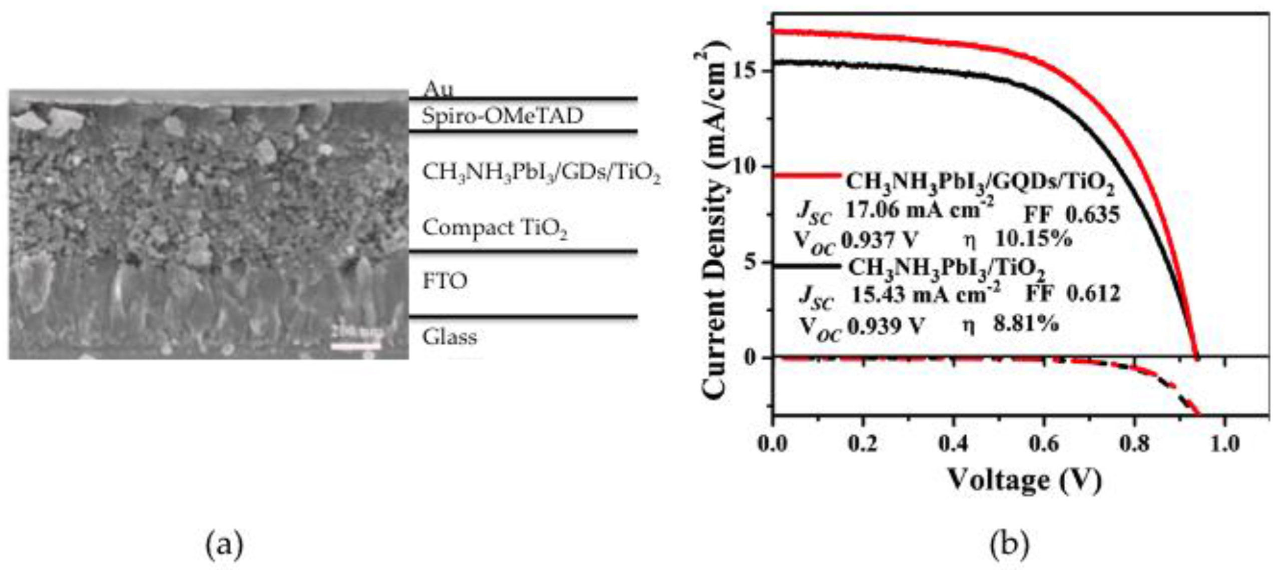
| E | Graphite rod | 5–10 | Hydroxyl, epoxy, carboxylic, carbonyl | PerSC | 17.06 | 0.937 | 63.5 | 10.15 | Improvement of charge extraction | [38] |
| E | Graphene film | 3–5 | Hydroxyl, carbonyl | PSC | 6.33 | 0.67 | 30 | 1.28 | Increment of exciton separation and charge transport. Non-optimized morphology | [39] |
| A | Graphite | 8.5 | --- | DSSC | 0.45 | 0.8 | 50 | 0.2 | Inefficient hole collection due to non-optimized thickness of GD layer | [40] |
| M | Glucose | 2.9 | --- | Si | 36.26 | 0.57 | 63.87 | 13.22 | Improvement of absorption in the UV and conductivity | [41] |
| A+H | Graphene oxide | 2–6 | Epoxy, carboxyl | Si | 23.38 | 0.51 | 55 | 6.63 | Reduction in current leakage | [42,43] |
| A | Carbon black | 10 | Hydroxyl, carboxyl | DSSC | 14.36 | 0.723 | 50.8 | 5.27 | Reduction in internal resistance and increment of charge transfer | [44] |
| A+H | Graphene oxide | <1 | Epoxy, carbonyl, hydroxyl | PSC | 15.2 | 0.74 | 67.6 | 7.6 | Increment in conductivity | [45] |
| A+H | Graphene sheets | 9 | Carboxyl 4 | PSC | 3.51 | 0.61 | 53 | 1.14 | Increase in exciton separation and charge transport | [46] |
| A+H | Graphene oxide | 50 | PEG | DSSC | 14.07 | 0.66 | 59 | 6.1 | Increase in light absorption | [47] |
| M | Glucosamine hydrochloride | 4.3 | amine | DSSC | 5.58 | 0.583 | 66 | 2.15 | Increase in light absorption and decrease of recombination | [48] |
| A | Carbon fibers | 20–30 | --- | PSC | 10.2 | 0.52 | 66.3 | 3.5 | Increase in conductivity | [49,50] |
| SMOPV | 11.36 | 0.92 | 65.2 | 6.82 |
© 2016 by the authors; licensee MDPI, Basel, Switzerland. This article is an open access article distributed under the terms and conditions of the Creative Commons Attribution (CC-BY) license (http://creativecommons.org/licenses/by/4.0/).
Share and Cite
Paulo, S.; Palomares, E.; Martinez-Ferrero, E. Graphene and Carbon Quantum Dot-Based Materials in Photovoltaic Devices: From Synthesis to Applications. Nanomaterials 2016, 6, 157. https://doi.org/10.3390/nano6090157
Paulo S, Palomares E, Martinez-Ferrero E. Graphene and Carbon Quantum Dot-Based Materials in Photovoltaic Devices: From Synthesis to Applications. Nanomaterials. 2016; 6(9):157. https://doi.org/10.3390/nano6090157
Chicago/Turabian StylePaulo, Sofia, Emilio Palomares, and Eugenia Martinez-Ferrero. 2016. "Graphene and Carbon Quantum Dot-Based Materials in Photovoltaic Devices: From Synthesis to Applications" Nanomaterials 6, no. 9: 157. https://doi.org/10.3390/nano6090157