Review

Structural Ceramic Nanocomposites: A Review of Properties and Powders’ Synthesis Methods

Department of Applied Science and Technology, INSTM R.U. PoliTO, LINCE Lab., Politecnico di Torino, Corso Duca degli Abruzzi, 24, Torino 10129, Italy
Nanomaterials 2015, 5(2), 656-696; https://doi.org/10.3390/nano5020656
Submission received: 6 March 2015 / Revised: 14 April 2015 / Accepted: 17 April 2015 / Published: 28 April 2015

Abstract

:
Ceramic nanocomposites are attracting growing interest, thanks to new processing methods enabling these materials to go from the research laboratory scale to the commercial level. Today, many different types of nanocomposite structures are proposed in the literature; however, to fully exploit their exceptional properties, a deep understanding of the materials’ behavior across length scales is necessary. In fact, knowing how the nanoscale structure influences the bulk properties enables the design of increasingly performing composite materials. A further key point is the ability of tailoring the desired nanostructured features in the sintered composites, a challenging issue requiring a careful control of all stages of manufacturing, from powder synthesis to sintering. This review is divided into four parts. In the first, classification and general issues of nanostructured ceramics are reported. The second provides basic structure–property relations, highlighting the grain-size dependence of the materials properties. The third describes the role of nanocrystalline second-phases on the mechanical properties of ordinary grain sized ceramics. Finally, the fourth part revises the mainly used synthesis routes to produce nanocomposite ceramic powders, underlining when possible the critical role of the synthesis method on the control of microstructure and properties of the sintered ceramics.

1. General Issues of Nanostructured and Nanocomposite Materials

Recent advances in the production of nanocrystalline ceramic powders with novel properties have stimulated the research to create multi-functional engineering materials by designing structures at the nanometric scale. Such recent enthusiasm in nanotechnology has also motivated the development of nanocomposite ceramics, which is one of the most rapidly evolving areas in composites research.
Nanotechnology can be broadly defined as the creation, processing, characterization and utilization of materials, devices and systems with dimensions of the order of 10–100 nm, exhibiting novel and significantly enhanced physical, chemical and biological properties, functions, phenomena and processes, due to their nano-scale size [1,2]. A nanomaterial has a typical grain size <100 nm, whereas ultrafine-grained materials are characterized by grain size <500 nm [3].
On the other hand, the term “nanocomposite” comprises multiphase materials, where at least one constituent phase has dimension of less than 100 nm [2].
The concept of structural ceramic nanocomposites was proposed by Niihara in 1991 and can be seen as the adoption of the nanocomposite approach for the microstructural tailoring of structural ceramic composites [4].
In order to classify the nanocomposite structures, we should firstly consider the different morphologies of the nanoscale reinforcements (Figure 1) [2]. In fact, nanoreinforcements can be grouped into three broad categories: (a) 3D-nanofillers (such as nanoparticles and nanospheres), which are relatively equiaxed with diameter <100 nm; (b) fiber or tube having diameter less than 100 nm and aspect ratio more than 100; (c) plate-like nanofillers, which can be layered materials with typically thickness of the order of 1 nm and aspect ratio in the other two directions at least of 25 [2].
Figure 1. Schemes and images of different types of nanoreinforcements, redrafted from [2]. Surface area/volume relations for different reinforcement geometries are also displayed.
Nanomaterials 05 00656 g001
The surface area/volume ratio for the different types of reinforcement is displayed in the same Figure. The change in particle diameter (2r), fibrous material diameter (2r) or layer thickness (t) from micrometer to nanometer changes the surface area/volume ratio by one or two orders of magnitudes (i.e., from 1 μm to 10 or 100 nm) [2]. This means that with the drastic increase in interfacial area, the properties of the composite are more and more dominated by the properties of the interface or interphase.
Typical composite nanocrystalline bulk structures are schematically presented in Figure 2 [4,5].
Figure 2. Scheme of common (nano)composite structures for ceramic materials, redrafted from [4] and [5]. (a) Micro/nano composite, with rounded nanoparticles occupying both inter- and intra-granular positions inside a micronic matrix; (b) Micro/nano composite, with elongated nanoreinforcements embedded in a micronic matrix; (c) Micro/nano composite, with platelet-like nanoreinforcements embedded in a micronic matrix; (d) Micro/nano composite, containing both rounded and elongated nanoreinforcements, embedded in a micronic matrix; (e) Bi-phasic composite made by two immiscible ultra-fine phases; (f) Multi-phasic composite made by three (or more) immiscible nanophases; (g) Nano/nanolayer type composite; (h) Nano- or micro-fibers embedded in a fine matrix; (i) Large second-phase precipitates embedded in a fine matrix.
Nanomaterials 05 00656 g002
The most common nanocomposite structures for ceramics consist of a micronic-sized matrix, in which nanoparticles are embedded [4]. In particular, the nanodispersions can be embedded in the matrix grains, located at the grain boundaries or occupy both inter- and intra-granular positions, as shown in Figure 2a. Examples of this structure can be found in the pioneer works of Niihara and co-workers related to nano-SiC particles dispersed in micronic Al2O3, S3N4 or Y2O3 matrix [6,7,8]. Other examples of micro/nano structures are displayed in Figure 2b,c, showing the presence of nanostructured elongated grains (whiskers, fibers or rod-like grains), (b) or platelets (c) embedded in a micronic matrix. The interest in such structures is explained by the in situ toughening effect exerted by the elongated grains and platelets, able to provide crack bridging and deflection mechanisms [9,10,11,12]. Recently, a new composite structure has been proposed in literature [13,14,15], consisting of both rounded and elongated nanostructured second-phase embedded in a conventional ceramic matrix, as shown in Figure 2d. Here, the rounded second-phase grains limit the matrix grain growth during sintering by exerting a pinning effect, with the aim of increasing the hardness and strength of the composites. The elongated grains, as previously explained, are chosen for their toughening effect, mainly due to crack deflection mechanisms. In Figure 2e, the structure of a nano/nano composite is displayed, consisting of approximately equiaxed nanoscale grains of two different phases. The two immiscible phases, contained in similar volume fractions, give rise to interconnected structures, in which each phase hinders the growth of the other, limiting the long-order interdiffusion. This concept can be extended to tri- or multiphasic systems, as shown in Figure 2f. In fact, raising the number of immiscible phases, the diffusion distance between homologous grains increases as well, thus further refining the overall composite microstructure [16]. In Figure 2g, a nanocrystalline composite consisting of grains of a single phase, divided by grain boundaries with a different chemical composition (second-phase) is represented [17]. Figure 2h,i show the structure of nanocrystalline composites consisting of elongated grains (h) or platelets (i) of one phase, embedded into a nanocrystalline matrix of the other phase.
In Figure 3, some examples of the above composite structures, experimentally developed, are reported [14,16,17,18,19,20,21,22,23].
Figure 3. Example of different kinds of developed ceramic composite/nanocomposite structures. (a) Micro/nano Al2O3/Y3Al5O12 (YAG) composite, with YAG predominantly located at Al2O3 grain boundary [18]; (b) Al2O3/ZrO2 composites, in which ZrO2 grains occupy both inter and intragranular positions [18]; (c) Ultra-fine Al2O3/50vol.%Y3Al5O12 (YAG) composite, with interpenetrating microstructure; (d) Y2O3-stabilized ZrO2 matrix containing elongated hexa-aluminate SrAl12O19 grains; (e) Triphasic composite, consisting on a ceria-zirconia matrix and containing both rounded α-Al2O grains and elongated hexa-aluminate SrAl12O19 grains [14]; (f) Ultra-fine Ultra-fine Al2O3/33vol.%Y3Al5O12/33vol.%ZrO2 composite [21].
Nanomaterials 05 00656 g003
In such different types of nanocomposite structures, a deep understanding of the materials’ behavior across length scales is required. Knowledge of how the nanoscale structure influences the bulk properties enables the design of the nanostructures, towards the fabrication of increasingly advanced and even multi-functional composites [2]. Once such knowledge is acquired, the tailoring of the desired composite structures is a further challenging step in the fabrication process. A successful approach requires the development of innovative concepts at each step of manufacturing, from the synthesis of composite nanopowders, to their processing and sintering. Nowadays, numerous technologies are available for producing highly pure, single-phase nanocrystalline powders [24]. In contrast, nanocomposite powders are still mainly produced by the traditional mixing and milling method, and it is striking the lack of advanced technologies applied to the synthesis of bi- or even multi-phasic systems, particularly at the industrial scale.
In this review, the attention focuses on ceramic-ceramic composite materials with macroscopically homogeneous structures, and in particular way will focus on particulate nanocomposite systems.
For a sake of completeness, this work will first consider the structural features of single-phase nanocrystalline ceramics (Section 2), and later those of nanostructured composites (Section 3). The final part (Section 4) is indeed dedicated to the synthesis methods of nanocomposite ceramic powders, with the aim of evidencing the key role of such manufacturing step in tailoring the micro/nanostructural features of the composites and the related final properties.

2. Why Nanostructured Ceramics?

Refining the material grain size in ceramics can induce significant changes on both mechanical and physical parameters. Therefore, the following paragraphs deepen some fundamental micro- or nano-structure-property relationships, with the aim of highlighting the size dependence of the materials properties.

2.1. Sintering and Grain Growth of Nanocrystalline Powders

To take advantage of the unique properties of bulk nanocrystalline materials, the nanometer range powders have to be densified into parts of certain properties, geometry and size. The key to the nanopowder consolidation process is to achieve densification with minimal microstructural coarsening and/or undesirable microstructural transformations. In particular, the grain growth normally occurring during the intermediate and final stages of sintering and the Ostwald ripening process should be avoided.
While the densification process for conventional powders is well known, the densification of nanopowders poses significant additional challenges, by both theoretical and practical points of view. First, due to the very large surface area of nanoparticles, agglomeration is an ubiquitous issue, affecting in a negative way the densification process. In addition, a still open question is whether the sintering mechanisms scale with grain size, and whether such mechanisms change when nanoscale is reached. A number of reviews have been already published addressing nanopowder processing and specific (nano)sintering issues [1,25,26,27].
As reviewed by Groza [25], nanopowders are highly unstable by a thermodynamic point of view. The tendency to reduce the excessively large surface area per unit volume of the nanocrystalline powders is the mechanism that drives the sintering process. The extra energy of a surface with a radius of curvature (R) may be calculated as a stress (σ), as given by the Laplace equation:
σ = γ R
where γ is the surface energy. In nanomaterials, this sintering stress may reach very high values. For instance, the sintering stress may be as large as 300 MPa in 10 nm particles compared to only 3 MPa for 1 μm particles, if γ has a typical value of 1.5 J/m2 [28].
From the kinetics point of view, we expect enhanced densification for processes that display a direct grain size dependence. For sintering, this dependence may be illustrated using the equation for the densification rate (dL/Ldt) developed by Johnson and co-workers, and used for all stages of sintering [29]:
d L L d t = γΩ k T   ( δ D b Γ b d 4 + D ν Γ ν d 3 )
where γ is the surface energy, Ω is the atomic volume, δ is the grain boundary width, Db and Dv are the grain boundary and bulk diffusivities, Γb and Γv are functions of density, k is the Boltzmann constant, T the temperature and d is the grain size.
From this equation, decreasing the grain size by one order of magnitude (e.g., from 1 μm to 100 nm) could enhance sintering rates by up to 4 orders of magnitude. Consequently, sintering of nanopowders may be accomplished at significantly lower temperatures and shorter time as respect to conventional powders. In fact, it was experimentally proved that the onset of sintering was significantly lower in nanoceramics (in the range 0.2–0.4 Tm) compared to conventional materials (0.5–0.8 Tm) [25,30,31,32,33]. However, to fully exploit the exceptional features of the nanocrystalline powders, they should be loosely dispersed, free from agglomerates. An example is provided in Figure 4, showing the sintering curves of Al2O3/50vol.%Y3Al5O12 (YAG) powders (referred to as AY). The powder, synthesized by co-precipitation route and calcined at 900 °C to crystallize γ-Al2O3 and YAG phases, is made by nanocrystalline particles, with both phases having a size in the range of 20–50 nm [34]. However, the powder presents a significant agglomeration, being the agglomerates of about 3 μm in size. Extensive ball milling was necessary in order to reduce the agglomerate size to about 0.5 μm. The black and red curves represent the linear shrinkage curves versus sintering temperature of the powder before and after milling, respectively. We can observe that the dispersed powder presents an onset sintering temperature (about 840 °C) well lower than the un-milled one (about 1000 °C). Therefore, the maximum sintering temperatures were observed at 1420 °C for the milled material, and at 1600 °C for the un-milled one. After the heating step at these two different temperatures, the materials reached the same densification degree, which was about 50% of their theoretical density. Full densification was reached, in both cases, by performing an isothermal step of three hours at the maximum sintering temperatures. More details about the sintering behavior of the two materials can be found elsewhere [34]. The lowering of the maximum sintering temperature of the milled-AY material had a critical effect on its sintered microstructure. As we can see in Figure 5, the un-milled material (sintered at 1600 °C/3 h, Figure 5a) presented a very homogeneous but micronic microstructure; on the opposite, the milled material (sintered at 1420 °C/3 h, Figure 5b) showed an ultra-fine grain size (about 300 nm) for both Al2O3 and YAG phases.
Figure 4. Linear shrinkage versus sintering temperature (during the heating step) of un-milled (black curve) and milled (red curves) AY powders. Maximum sintering temperatures were 1420 °C and 1600 °C for the milled and un-milled powders, respectively [34].
Nanomaterials 05 00656 g004
Figure 5. Transmission Electron Microscopy (TEM) images of AY materials. (a) Un-milled powder, sintered ad 1600 °C/3 h; (b) Milled powder sintered at 1420 °C/3 h. Characters A and Y refer to α-Al2O3 (black grains) and YAG (white grains), respectively.
Nanomaterials 05 00656 g005
In 1950, Herring [35] developed the classical scaling rule, correlating the effect of the particle size on the sintering time. The time, t, to achieve the same sintering condition is correlated to the powder particle size, d, by the equation:
t 1 t 2 = ( d 1 d 2 ) n
where the exponent n depends on the sintering mechanism (in this equation, it is assumed the same sintering mechanisms, independently from the particle size). Considering the Arrhenius expression for temperature, the sintering temperature dependence on the particle size becomes:
n l n ( d 1 d 2 ) = Q R [ ( 1 T 1 ) ( 1 T 2 ) ]
where Q is the activation energy for the predominant sintering mechanism, R is the gas constant, d1 and d2 are the different powder particle sizes and T1 and T2 are their respective sintering temperatures.
Considering Herring’s law, the sintering temperature dependence on the particle size may be calculated. Reasonable agreement of experimental and calculated temperatures was found in TiO2, and Al2O3 assuming certain diffusion mechanisms [25]. Zeng et al. [36] demonstrated that the Herring scale law can be used to predict the approximate sintering temperature of α-Al2O3 powder and showed that if the particles size was reduced to <20 nm, sintering below 1000 °C may be possible.
Yttria-stabilized zirconia powders (at different yttria contents) were submitted to a two-step sintering process, with the aim of achieving full densification but minimizing grain growth [37]. Pressureless two-step sintering is a relatively new method to obtain dense ceramics with restricted grain growth. As originally proposed by Chen and Wang in [38], the suppression of the grain growth in the final sintering stage may be achieved by exploring the kinetic window between grain boundary diffusion and grain boundary migration. A typical two-step sintering schedule consists of a first heating step to a peak temperature (Tp) sufficient to reach a relative density higher than 75%. This step is then followed by a rapid cooling down to an isothermal plateau at a lower temperature (Td) for a relatively long time (td), in which full densification should occur via a relatively slow grain boundary diffusion process. For yttria-stabilized zirconia, the conditions required for the effective two-step sintering were evaluated by shrinkage experiments performed on heating at constant rate. Data were interpreted on assuming the classical Herring’s law describing the shrinkage during the second stage of sintering [38]. By using this approach, high density (around 95%) tetragonal (ZrO2)0.97(Y2O3)0.03 and cubic (ZrO2)0.92(Y2O3)0.08 ceramics were obtained, respectively showing a nanometric and sub-micrometric microstructure.

2.2. Mechanical Behavior of Nanocrystalline Ceramics

2.2.1. Hardness and Strength

Mechanical behavior of nanocrystalline materials has been the theme of over 500 publications and several review articles [24,25,26,39,40]. Most of these articles conclude that the yield stress (τ) and the microhardness (Hv) of nanocrystalline materials can be 2–10 times higher than the corresponding coarse-grained polycrystalline materials, with the same chemical composition. These behaviors are described by the empirical Hall–Petch relationships, according to the following equations:
τ = τ0 + k·d ½
Hv=H0 + k·d ½
where H0 is the intrinsic hardness dependent on frictional lattice resistance to dislocation motion [41], τ0 is a material constant [39], k is the material-specific strengthening coefficient, and d is the average grain size.
The Hall-Petch law is based on the theoretical [40] and experimental [42] observation that grain boundaries impede dislocation slip, which is the principal deformation mechanism accommodating strain during plasticity. In addition, it was proved that smaller grains limit the size of dislocation pile-up, which affects how easily dislocations can traverse grain boundaries and travel from grain to grain. Therefore, a higher applied stress is necessary to propagate dislocations from grain to grain and to induce a permanent deformation to a material: as a result, both yield strength and hardness are enhanced [39]. As an example, Figure 6 displays different microstructures of YAG ceramics, fabricated at increasing Spark Plasma Sintering (SPS) temperatures (from 1325 °C to 1400 °C), reaching full density [43]. Average grain size and Vickers hardness were determined for all materials. As shown in Figure 6, an inverse proportion between grain size and hardness can be clearly stated [44].
Figure 6. Field Emission Scanning Electron Microscopy (FESEM) micrographs of Y3Al5O12 (YAG) sintered by Spark Plasma Sintering (SPS) at increasing temperatures (Hv = average Vickers hardness; GS = average grain size) [41].
Nanomaterials 05 00656 g006
However, further refinement of grain size may lead to lower yield stress. Thus, some materials exhibited the so-called “inverse” Hall-Petch behavior, showing a decreased hardness with further reduction of grain size. While this phenomenon has been widely explored in nanocrystalline metallic materials, few data refer to nanocrystalline ceramics due to the difficulty associated to the fabrication of high-quality, dense nanostructured materials. In spite of this, a recent paper of Wollmershauser et al. [45] showed that the hardness of magnesium aluminate spinel, used as a model hard ceramic material, rigorously followed the Hall-Petch relationship down to grain sizes of 28 nm.
Besides the Hall-Petch equations, the Griffith theory also provides fundamental understanding of the mechanical behavior of ceramics. In fact, for elastic brittle materials, the fracture behavior can be analyzed by using the Griffith equation:
σ f =   K I C Y   π a
where σf is the strength, KIC is the fracture toughness, a is the flaw size and Y is a geometric factor related to the failure origin, approximately equal to 1 [46]. From this equation, we can see that for increasing the strength of a brittle material, both an increase of KIC and a decrease of a are needed. Flaws of some statistically distributed size are always present in a ceramic material. They may arise during manufacturing or in subsequent handling of the material. Since polycrystalline ceramics are usually manufactured by sintering a powder compact at high temperature, the flaws may arise from non-uniformities in the particle packing. The refinement of the microstructure allows decreasing the material flaw size produced during processing: for this reason, it is generally assumed that the fracture strength in nanoceramics is higher than in conventional micronic-sized materials.

2.2.2. High-Temperature Mechanical Properties

A further difference between nanocrystalline and coarse-grained materials lies in the high-temperature mechanical behavior. The creep behavior of coarse-grained materials has been extensively studied over the past four decades. These studies allowed establishing that the creep behavior of a polycrystalline material can be represented by the following expression [47]:
γ ˙ = A ( D G b k T ) ( b d ) s ( τ g ) n
with:
D = D 0 exp ( Q R T )
where γ is the shear creep rate, A is a dimensionless constant, D is the diffusion coefficient that characterizes the creep process, G is the shear modulus, b is the Burgers vector, k is Boltzmann’s constant, T is the absolute temperature, d is the grain size, s is the grain size sensitivity, τ is the applied shear stress, n is the stress exponent, Q is the activation energy for the diffusion process that controls the creep behavior, D0 is the frequency factor for diffusion.
Starting from these general equations, two models have been formulated: the former, the Nabarro–Herring creep [48,49] involving the diffusion of vacancies through the grain volume; the latter, the Coble creep [50] involving the diffusion of vacancies along the grain boundaries. Once again, there is a role of the grain size on these behaviors: in fact, it was reported [51] that Coble mechanism could prevail over the Nabarro-Herring one at very small normalized grain size. Particularly, the Coble creep is defined by the following equation:
ε ˙ C o =   A C o   G b   D g b k T   ( b d ) 3   σ G
showing a cubic dependence of the creep rate on d. A reduction in grain size from 10 μm to 10 nm would produce an increase in the creep rate by nine orders of magnitude, all else being constant, thus suggesting the possibility of deformation at room temperature [52,53]. In nanocrystalline ceramics, this feature has not been demonstrated yet. A previous study on nano-scale TiO2 has shown extensive ductility at room temperature [54]; however, subsequent investigations showed that ductility was due to the presence of porosity, an extrinsic effect not directly related to grain size [55,56,57]. This example clearly shows that the nanocrystalline domain of ceramic materials deserve further investigations. In fact, contrary to metals and alloys, few and sometime contradictory data refer to ceramic materials, as the fabrication of highly dense, nanostructured ceramics is still a complex issue.

3. Why Nanocomposites Ceramics?

3.1. Sintering and Grain Growth of Nanocomposite Ceramics

The addition of nanocrystalline second-phases to ordinary grain sized ceramics is very effective in reducing the particles grain growth during sintering. In fact, dopants or second-phase particles, which are insoluble in the matrix phase, can decrease the coarsening kinetics of the matrix itself by reducing the grain boundary mobility through a particle pinning effect.
This behavior was described in the Zener’s theory [58] in 1948, showing that the inclusion exerts a drug force on the grain boundary given by:
F= 2πr γsinθ cosθ
where F is the pinning force, r is the particle radius and γ is the average boundary energy of the system. If particles are assumed to be spherical and γ to be isotropic, the maximum value of the force, Fmax, is given when θ = π/4:
Fmax = πrγ
The number of particles per area of boundary, Ns, can be approximated by considering the particles to be distributed randomly on the boundary. Therefore:
N s = 3 f 4 π 2
where f is the volume fraction of particles. Combining Equations (12) and (13), the pinning stress can be derived:
σ z = 3 f γ 4 r
In this theory, we should consider that numerous assumptions have been made: for instance, it applies to spherical and randomly distributed particles; it is assumed that each particle in contact with the boundary exerts the maximum force, whereas the pinning force exerted by each particle also depends on the position of the boundary.
The force on a boundary due to non-spherical particles has been calculated in 1983 by Ryum et al. [59], who considered needle- and plate-shaped particles. They evaluated the force as a function of aspect ratio of the angle between the boundary and the axis of the particle. If was found that the pinning force is a function of particle shape, large forces being associated with large differentials in the cross sectional area presented to the boundary. Thus, a needle particle with an aspect ratio of 5 can exert a force of 2Fmax on a boundary. Since the pinning force differs from the spherical case, we might expect that the pinning stress would be similarly affected. However, if the particles are randomly orientated, the pinning stress given by the previous equation is still a good approximation.
Finally, for spherical particles, the dependence of the matrix grain size (R) on the particle size and fraction can be also estimated, according to the following relationship:
R = 4 r 3 f
The incorporation of nanoparticles into ceramics to control grain size during thermomechanical processing is now standard industrial practice. Second-phases such as fine YAG [60,61], ZrO2 [62,63,64,65], SiC [66], Si3N4 [67] NbC [68] are commonly added to Al2O3, to inhibit the matrix grain size and therefore increase the mechanical properties [69]. Figure 7 compares the microstructures of a pure CeO2-stabilized ZrO2 and the respective composite material, containing 16vol.% of α-Al2O3, both sintered at 1450 °C for 1h. The fine and homogeneous distribution of the ultra-fine α-Al2O3 grains induces a very effective pinning effect on the ZrO2 grain boundaries: as a result, the ZrO2 average grain size decreases from about 4 μm in the monolithic material to about 0.7 μm in the composite [70].
Figure 7. FESEM micrographs of (a) pure CeO2-stabilized ZrO2 and (b) the respective composite containing 16vol.% of α-Al2O3, both sintered at 1450 °C for 1h [70].
Nanomaterials 05 00656 g007

3.2. Mechanical Properties of Nanocomposite Ceramics

3.2.1. Hardness and Strength

As previously reported, the incorporation of ultra-fine second-phase particles can reduce the matrix grain growth. This has a general positive effect on the mechanical properties, since an increase in strength and hardness is expected on the ground of the Hall-Petch relation (see Equations (5) and (6)).
A further explanation of the increased strength of the nanocomposites is the reduction in the size of processing flaws. An example is provided by the Al2O3/SiC nanocomposite system, processed by extensive milling of Al2O3 and SiC raw powders. It was proved that during this step, the SiC particles act as grinding medium during attritor or ball milling and successfully destroy the Al2O3 agglomerates, which commonly cause large processing flaws [71,72]. This is illustrated in Figure 8 [72], in which we can see a continuous decrease of the flexural strength by increasing the flaw size in Al2O3/SiC ceramics. Values show that the flaw size should be very small to produce high-strength ceramics, meaning that a careful manufacturing during the ceramic processing is needed.
Figure 8. Evolution of flexural strength with the flaw size in Al2O3/SiC composites [69].
Nanomaterials 05 00656 g008
On the other hand, the SiC grains should also achieve an optimal distribution in the Al2O3 matrix, avoiding agglomeration. This is usually achieved for low SiC contents (up to 5vol.%) allowing to increase the Al2O3 strength from about 350 MPa to about 1050 MPa, whereas further addition of SiC lowers the strength due to agglomeration phenomena [71].
In general, the strength of the composites can be estimated by the rule of mixtures. However, mechanisms that lead to a toughness change, such as microcracking or phase transformation (discussed later) may significantly alter the strength. In the previous example of Al2O3/SiC composite, the decreased strength above a certain volume fraction of SiC has been also imputed to microcrack linkage [73]. Similar results were obtained for the Al2O3/ZrC system: the flexural strength increased from about 300 to 550 MPa upon addition of 5–10mol.% ZrC, above which it decreased to the initial value [74].
Ohji et al. [75] have proposed a “nanotoughening” effect for explaining the strengthening of the Al2O3/SiC system. A mechanism based on near-tip crack bridging by the nanosized SiC inclusions was considered to produce a modest toughness increment but a very steep R-curve, and this latter produces the very high fracture strength of the ceramic nanocomposites.
A further difference between monolithic ceramics and related nanocomposites is the fracture mode. Again with reference to the Al2O3/SiC system, it was observed that the fracture mode changed from a mixed inter/transgranular fracture mode in monolithic Al2O3 to pure transgranular mode in the composites, highlighting a grain boundary strengthening in this latter case. Ferroni and Pezzotti [76] estimated that the amount of transgranular fracture mode in monolithic Al2O3 was about 10%. This value increased to about 55%–85% in Al2O3/SiC nanocomposites, depending on the SiC amount. In particular, at the lowest SiC content (5vol.%), the highest fraction of transgranular fracture mode was determined. However, this behavior was directly related to the amount of SiC particles located in inter or transgranular position as respect to the Al2O3 matrix. The predominant transgranular crack path was observed when SiC grains were mainly located within the Al2O3 matrix [76].
Conceivable reason for the grain boundary strengthening is the local internal stress, as for instance reported in [75,77]. In monolithic Al2O3, residual thermal stress is imputed to the thermal expansion anisotropy experienced by non-cubic ceramics during cooling from the sintering temperature. In these ceramics, triple points are inherently weak zones due to high residual stress during cooling. Figure 9a schematically shows a grain boundary microcrack due to local tensile stress, arising from thermal expansion anisotropy [76]. In composites, residual thermal stresses are imputed to the difference in thermal expansion coefficients between matrix (αm) and particle (αp), which cause strain during cooling from high-temperature sintering [71]. Thus, when second-phase grains, with lower thermal expansion, are embedded in the matrix grains, a hydrostatic compressive stress field can be generated on a grain boundary during cooling (see Figure 9b).
Figure 9. Schematic illustration of the residual stress field in (a) pure Al2O3, due to thermal expansion anisotropy during cooling and (b) Al2O3/SiC nanocomposites, due to thermal expansion coefficient mismatch between matrix and second-phase. In both figures, the preferential crack path is illustrated.
Nanomaterials 05 00656 g009
The thermal expansion misfit stress, σT, inside a single spherical inclusion in an infinite matrix is described by the Selsing expression [77]:
σ T = α * 1 + ν m 2 E m + 1 2 ν p E p
where <α*> is the thermal expansion misfit strain, E and ν are Young’s modulus and Poissons’s ratio of the matrix (m) and particles (p). In the case in which αm > αp, the average thermal stress are compressive inside the second-phase particles and tensile in the matrix.
This is the case of the Al2O3/SiC system, where the SiC particles have lower thermal expansion coefficients than Al2O3. This induces compressive and tensile residual stress in the radial and tangential directions, respectively, of the Al2O3 matrix around the particle [76], as shown in Figure 9b. We can see that both Al2O3 and Al2O3/SiC grain boundaries are subjected to a hydrostatic compressive stress field, whereas the matrix is under a tensile stress. The direct consequence is the transgranular fracture mode, propagating inside both Al2O3 matrix and second-phase particles, as schematically illustrated in Figure 9b.
Finally, it should be mentioned that large differences in α coefficients between matrix and second phases (as in the case of Al2O3/SiC system) usually increase the possibility of microcracking, since the particles are under high local stresses. This limits the second-phase content in the ceramic matrix. A different case is provided by the Al2O3/TiC composite, which is a well-established cutting tool material, showing improved strength as compared to Al2O3 alone. In this system, high strength values can be retained at relatively high TiC contents, due to the smaller difference in α coefficients between TiC and Al2O3 [78], if compared to the Al2O3/SiC system.

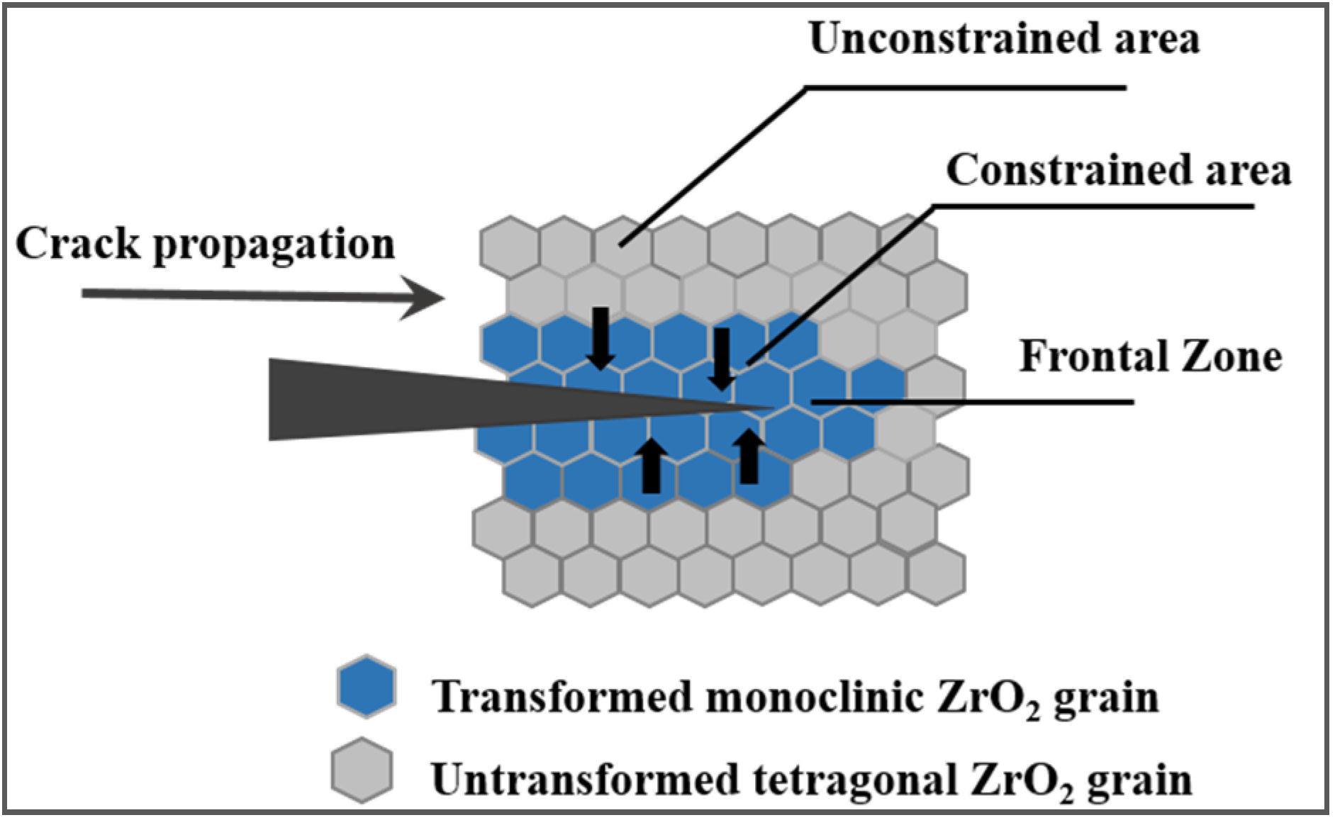
3.2.2. Fracture Toughness

Beside their strengthening effect, nano-sized second-phase particles can also increase the toughness of the monolithic ceramic material.
Toughness is a term used to define the resistance of a material to crack formation and propagation. It is also defined as the ability of a material to absorb energy before failure. Fracture toughness (KIC) is defined as the critical stress intensity above which a crack will propagate and result in failure of the material [73]. The subscript I represents mode I displacement, i.e., the load is perpendicular to the crack. For brittle materials, and according to Griffith’s equation, KIC can be expressed by rewriting Equation (7) as follows:
KIC = σfY√πa
Being σf the critical stress, a the half crack length, Y a constant depending on crack configuration and loading geometry.
In ideally elastic (brittle) materials, crack propagation occurs catastrophically if the crack size is above a critical size, ac. At crack size a < ac, subcritical crack growth may occur due to environmental effects, i.e., stress corrosion, resulting in crack growth to the critical size and failure. The environmental effect on crack growth is best represented by crack velocity (V)-toughness (KI) curve [79], as shown in Figure 10a. Segment I corresponds to chemically enhanced crack growth: below the threshold value, Kth, cracks do not propagate. Segment II (plateau region) corresponds to region with a combination of stress and environment, where minor species in a liquid or gas control the crack tip reaction. Segment III is independent from the environment: microstructure, material thickness and stress have a major influence on the crack growth rate within this segment.
If the ceramic is not ideally elastic, i.e., if it is toughened as happens in most composite ceramic systems, it generally exhibits R-curve behavior, meaning that the toughness rises within the crack length a, as shown in Figure 10b. Above a critical crack size (ac), steady state toughness is reached.
Figure 10. (a) Scheme of crack growth rate-stress intensity behavior; (b) Rising toughness with increasing crack size (R-curve behavior).
Nanomaterials 05 00656 g010
R-curve behavior is typical in ceramics toughened by second-phases (such as ZrO2, whiskers or fibers). The slope of the R-curve is an indication of the toughening rate during crack opening.
Increasing the toughness of ceramics is of critical importance, in particular if we consider their industrial manufacturing. Increased fracture toughness levels can significantly reduce the number of parts rejected during production and increase reliability during service, with a positive impact on the production costs. For this reason, there has been a considerable amount of research aimed at increasing the toughness of ceramics [73].
In this contest, nanocomposite ceramics are attracting increasing interest, since the dispersion of second-phase nano-grains can enhance the toughness of ceramics.
Crack bowing, which consists on the bowing of cracks between obstacles (i.e., second phases) [73], is recognized as a toughening mechanism in composite ceramics: Lange [80] suggested that the interaction of a crack front with two or more resistant second-phase components can increase the fracture length and therefore the fracture energy along with the strength. Green [81] related the change in fracture energy to the fracture toughness change when crack bowing occurs by the following equation:
σcm = Kc/Km = (EcΓc/EmΓm)1/2
where σc is the stress needed to propagate a crack through a series of second phases, σm is the matrix fracture strength, Kc and Km are critical stress intensity factor, Ec and Em are elastic moduli and Γc and Γm are fracture surface energy. Subscripts c and m denote composite and matrix, respectively.
Faber and Evans [82] further developed the crack bowing theory, by investigating the role of second phases having different morphologies, such as spheres, discs and rods, showing that the highest toughening is achieved in high aspect ratio disks within a brittle matrix. Faber and Evans [82] also investigated crack deflection phenomena, where crack deflection is different from crack bowing since the former produces a nonplanar crack, the latter a nonlinear crack front. Crack bowing and crack deflection have been recognized as the main toughening mechanisms where metal carbide second-phase are added to ceramic matrix, as shown in [82,83,84].
The change in fracture mode, from mixed inter/intragranular in monolithic ceramics to pure transgranular in nanocomposites also provides a toughening effect: the higher the extent of transgranular fracture, the higher the toughening [85]. Even more effective is the case of wavy fracture surface, occurring when a crack path is perturbed by subsequent particles embedded in a matrix. The wavy crack path enlarges the area of the crack surface and thus improves the toughness [85].
Recently, Awaji and co-workers [86] have underlined a relationship between the fracture toughness with the critical Frontal Process Zone (ZPS) size in nanocomposite ceramics. This model mainly applies to intra-type composites, in which the FPZ expansion ahead of a crack tip, founded on the Evans–Feber nanocrack mechanism [82], is considered the major factor responsible for the toughening increment in nanocomposites. Based on numerical modeling and experimental observations of Al2O3/SiC nanocomposites, dislocations are created in a temperature range from 600 to 1400 °C. During cooling, the thermal mismatch between matrix and second-phase particles allows the creation of sessile dislocations, which, at room temperature, will be localized close to the nanoparticles. Further annealing induces a dislocation rearrangement, leading to the development of dislocation networks or sub-grain boundaries around the particles [86]. When a main crack tip approaches this area, the dislocations act as nanocracks nuclei: the formation of many nanocracks expands the size of the FPZ of ceramics and hence improves the fracture toughness of the material. In addition, the sessile dislocations around the particles partially release the tensile residual stress in the grains and grain boundaries, thus strengthening the nanocomposite.
Beside the toughening mechanisms previously described, transformation toughening deserves to be discussed [3,73]. Such behavior is presented by ceramics containing fine metastable ZrO2 grains, whose phase transformation is able to increase the crack propagation resistance. To explain such phenomenon, we should introduce the three polymorphisms of ZrO2, being progressively monoclinic (m), tetragonal (t) and cubic (c) at increasing temperatures. By adding proper stabilizers, such as yttrium oxide, the metastable t phase can be retained at room temperature, being able to re-transform into the stable m phase under an applied stress. As this martensitic transformation involves a volume expansion of ~3%–5% and a large shear strain (~7%) [73], it can induce a compressive stress at the crack tip and avoid the crack propagation, with a consequent toughening effect. A scheme of the transformation toughening mechanism is given in Figure 11.
Figure 11. Schematic illustration of stress-induced phase transformation toughening.
Nanomaterials 05 00656 g011
Several conditions are required for transformation toughening to occur and the following parameters must be optimized:
(i)
The ZrO2 particle size;
(ii)
The stabilizing phase concentration;
(iii)
The particle size distribution;
(iv)
The particle-matrix thermal expansion mismatch.
In particular, it should be mentioned that unstabilized ZrO2 particles that are larger than a critical size will transform spontaneously during cooling, whereas particles which are too small do not transform, even under stress [73]. This highlights the key role of tailoring the microstructure during processing and sintering, in order to fully exploit the stress-induced phase transformation and maximize the mechanical properties.
Microcracking is a further toughening mechanism, derived from studies on ZrO2-toughened ceramics [87]. In fact, the relation between toughness increment in brittle solids and thermally or stress-induced microcracks was first demonstrated in Al2O3/ZrO2 system. Ceramic structures that contain localized residual stresses are susceptible to microcracking. Stresses can arise from phase transformation, thermal expansion anisotropy in monolithic ceramics and thermal expansion or elastic mismatch in composite ceramics. For microcracking to occur, stress-induced microcracking must be generated within a limited zone of stress concentration, near the crack tip. In addition, microcracking is possible only if the size of the dispersion exceeds a critical particle size [63].
Toughening is described by the Evans and Faber relations; in particular, for non-interacting second-phase spheres, under a residual stress (σR), toughening is given by:
ΔKIC = 1.12VσRh1/2(1 + ν)
where V is the volume fraction of spheres, h is the microcracking process zone and ν is the Poisson coefficient. In case of phase transformation associated to volume increase, as happens in martensitic transformation of zirconia, microcracks are expected to form radially from second-phase particles into the matrix. In this case, toughness increment is given by:
Δ K I C = 0.21 E e T h 1 2 ( V + 0.6 V 1 3 ) ( 1 ν )
where eT is the volumetric strain of transformation, E the elastic modulus.
Transformation shielding has been recognized as the most effective toughening mechanism. In spite of this, experimental results show that when transformation is simultaneously accompanied by microcracking, the toughening effect is even more effective [88,89].
Finally, even if this review is mostly focused on particulate-reinforced ceramics, we should at least mention the important toughening effects of elongated second-phase or whiskers: here, toughening is mainly imputed to crack deflection, whisker pull-out and crack bridging mechanisms, as reviewed by Bengisu [73].

3.2.3. High-Temperature Mechanical Properties

The presence of discrete, hard second-phase particles added to a ceramic matrix modifies the creep response of the materials, generally increasing its creep resistance. However, the scale of the effect depends on the volume fraction and morphology of the second-phase and how it is distributed in the matrix [90]. For instance, if the volume fraction of the second-phase is small, then the particles behave independently and the effect is only due to the disturbance of the flow field around the particles, resulting, for example, from a local increase in the effective path length for diffusion. As the particle fraction increases, antiparticle interactions begin to have effect. For example, local cluster of particles behave similarly to larger, single particles [90].
For two-phase composites, there are several equations which may express or predict their high temperature creep behavior: among them, we can recall the Raj and Ashby model [91]:
ε ˙ = C σ n V d p r q exp ( Q R T )
where V is the second phase volume content, r is second phase grain radius, q and n are phenomenological exponents and C is a constant. This model applies to composites in which the second-phase can be considered rigid, and assumes that the hard second-phase particles limit the grain boundary sliding of the matrix. From the expression, we can see that the higher the second-phase volume fraction and the larger their size, the lower the creep rate.
Generally, for two-phase composites, especially for those with duplex microstructures, authors are not only interested in the dominant mechanism of deformation, but also try to find out which phase controls the creep behavior. Many investigations relate to Al2O3-based composites, in which SiC, YAG, ZrO2 and TiO2 are the mostly used second-phases. Such works demonstrate that the deformation behaviors are critically dependent on the physical and chemical properties of reinforcing particles or whiskers (including their content, morphologies and distributions), on the microstructures of composites (including grain sizes and shapes, pores, grain boundaries, interfaces), on the stress and temperature. During deformation, microstructural changes often occur, such as grain growth, changes of grain shape (grain elongation), texture development, formation of intermediate or intergranular phases, dislocation activity, vacancy nucleation and evolution, cavitation and evolution, formation and development of microcracks, etc. The study of such microstructural changes accompanying creep deformation is an essential aspect for analyzing creep deformation behaviors and creep mechanisms of composites [91].
Al2O3/SiC and Al2O3/YAG materials provided experimental evidence of the increased creep resistance of the nanocomposites as respect to monolithic Al2O3 [92,93,94,95]. The addition of SiC particles increases the creep resistance by one to two orders of magnitude in comparison to the monolithic Al2O3 [92,93,94,95]. The effect has been attributed to residual thermal stresses, created around SiC inclusions during cooling from the sintering temperature, as already reported. In particular, compressive residual stresses are created at the Al2O3/SiC interfaces (see Figure 9b), giving rise to stronger particle/matrix bonding as respect to matrix/matrix (i.e., Al2O3/ Al2O3) bonding [96]. Furthermore, intergranular SiC particles exert a pinning effect on the Al2O3 grain boundary, inhibiting the grain boundary sliding and thus increasing the creep resistance [97]. YAG is considered one of most creep resistant oxide ceramic [98] and its addition to Al2O3 provides a decrease of the creep rate of one order of magnitude [94]. A previous study [99] showed that the creep rate was controlled by YAG (the more creep-resistant phase) and suggested a diffusional Nabarro–Herring mechanism.

4. Synthesis of Nanocomposite Ceramic Powders

As previously reported, the addition of nanosized or ultra-fine second-phases can induce significant increments in the materials mechanical properties, in terms of hardness, strength, fracture toughness and creep resistance.
However, a key point to achieve excellent mechanical properties in nanocomposite ceramics is a proper design and fabrication process to yield tailored sintered micro/nanostructures. When designing a composite structure, besides considering the chemical composition of matrix and second-phase, the amount, distribution, morphology of the reinforcement phase should be properly evaluated. A key point is achieving a homogenous distribution of the second-phase in the matrix material, but this is still challenging when nanocrystalline particles are used, due to their extremely high specific surface and, hence, intrinsically high tendency to agglomeration. This means that all manufacturing steps towards the elaboration of nanocomposite ceramics should be carried out with particular care, from the synthesis of the composite powders, to the forming of green bodies and their sintering. Although the processing and sintering routes of nanoceramics have been revised in some previous papers [1,100], the role of synthesis on the microstructure and properties of sintered composite ceramics have been poorly discussed in literature.
The most investigated structural ceramic nanocomposites are Al2O3/SiC and Si3N4/SiC. However, many other different phases such as TiN, TiC, TiO2, ZrO2, Cr3C2, YAG, can be used as nanoreinforcements in Al2O3, Si3N4, MgO, mullite or SiAlON ceramic matrix. In the following, the mainly used synthesis routes for the above composite systems are reviewed. First, the traditional mixing and milling method of single-phase ceramic powders to produce a composite feedstock, is described. Then, the more advanced synthesis methods used for directly producing composite powders are described. For sake of clarity, Table 1 summarizes direct composite powder synthesis methods and provides some examples of compositions already developed.
Table 1. Synthesis methods of nanocomposite ceramic powers and examples of developed compositions.
Synthesis RouteType of CompositeCompositionReferences
MechanochemicalOxide/oxideHA/MgTiO3/MgO; β-CP/MgTiO3/MgO[101]
Oxide/non-oxideAl2O3/ZrB2/ZrO2; Al2O3/TiB2[102,103]
Non-oxide/non-oxideB4C/SiC, NbC/NbB2[104,105]
Polymer precursorOxide/non-oxideAl2O3/SiC; Mullite/SiC[71,106,107,108]
Non-oxide/non-oxideZrC/SiC; Si3N4/SiC[109,110,111,112,113,114,115,116]
Vapor PhaseOxide/oxideZrO2/SiO2; TiO2/V2O5[71,117]
Non-oxide/non-oxideSi3N4/SiC[71]
SHSOxide/non-oxide
Non-oxide/non-oxide
Al2O3/SiC; Mullite/TiB2[118,119]
[120,121,122,123,124]
Si3N4/TiN;Si3N4/MoSi2; Si3N4/SiC;
TiN–SiC–Si3N4; ZrB2–SiC–ZrC–ZrSi
Sol-gelOxide/oxideAl2O3/ZrO2;Al2O3/Y3Al5O12;[125,126,127,128,129,130]
Mullite/ZrO2; Mullite/TiO2
Oxide/non-oxideAl2O3/SiC; Mullite/SiCAlN/BN[131,132,133,134]
Non-oxide/non-oxideMullite/SiCAlN/BN[135]
Co-precipitationOxide/oxideAl2O3/ZrO2;Al2O3/Y3Al5O12; ZrO2/Gd2O3; Al2O3/LaAl11O18; Ca10(PO4)6(OH)2]/Fe2O3/Mullite/Al2O3.[34,136,137,138,139,140,141,142,143]
Solution combustion/Oxide/oxideAl2O3/ZrO2; CeO2–MxOy; MOx–ZnO;[73,144,145,146,147,148,149,150,151]
Spray decompositionγ-Fe2O3–TiO2; Al2O3/ZrO2/MgAl2O4
Surface modification routeOxide/oxideAl2O3/ZrO2; Al2O3/Y3Al5O12; Al2O3/Mullite; Al2O3/SiO2; ZrO2/MgAl2O4; Al2O3/ZrO2/Y3Al5O12; ZrO2/Al2O3/SrAl12O19[14,16,21,62,70,88,152,153,154,155,156,157,158,159]
Oxide/non-oxideSiC/Al2O3; SiC/Y2O3[160]

4.1. Conventional Powder Route

Most ceramic composite powders are currently produced by mechanical mixing of the constituent phases. This route involves the selection of raw materials, paying particular attention to the primary particle size, size distribution, agglomeration degree and purity. High purity powders are necessary to avoid the formation of a secondary phase during sintering. A wide particle size distribution on one hand leads to a higher packing density in the green bodies. On the other hand, the control of the microstructural development during sintering could be difficult because the larger grains can coarsen, including the smaller ones. At the same time, the particle size influences the final grains size and the densification rate (see Section 2.1 and Section 3.1): due to the higher specific surface, the densification rate increases as the particle size decreases. In addition, if the powder is characterized by a certain agglomeration degree, the packing in the green density will be heterogeneous, giving rise to differential sintering rates and to heterogeneous microstructures. In addition, a not homogeneous particle packing can produce large flaws, with a negative effect on the strength of the sintered composite, as shown in Section 3.2.1. For this reason, ultra-fine, loosely dispersed powders are needed for both matrix and reinforcing phases, to guarantee effective mixing and satisfactory dispersion of second-phase grains in the final product. In addition, the crystalline phase of the raw powder can play a role on the densification behavior and microstructural development. In the case of Al2O3-based composites, both transition Al2O3 (such as γ-Al2O3) and α-Al2O3 can be used. The main advantages in the use of γ-Al2O3 powder are its finer particle size, the loosely packed morphology and high surface area. However, the transformation from metastable, transition phases (i.e., γ and θ phase) to α-Al2O3 occurs by a nucleation and growth mechanism. This transformation is accompanied by a volume reduction of about 10.2%, due to the higher density of the α-phase and a change in grain morphology. In fact, a well-known vermicular morphology is produced, due to the high temperature finger growth of α-grains into the θ-Al2O3 matrix, entrapping a network of large, elongated pores. Therefore, the final stages of sintering require very high temperature to achieve full densification, thus leading to a significant grain growth [161]. For this reason, α-Al2O3 particles are usually the preferred choice as raw materials for both monolithic Al2O3 parts and related composite materials.
The homogenization of the powder mixture can be achieved by either wet ball or attrition milling, carried out in aqueous or organic media. Al2O3/SiC composites are frequently prepared by this conventional powder mixing route, by using ball-milling as well as ultrasonic dispersion [71]. The most critical step is drying, because of the risk of agglomerate formation. An infrared heat lamp or freeze drying was successfully used to avoid such a drawback [71].
In spite of such expedients, the major drawback of this method is the inability to achieve an optimal distribution of ultrafine (~50 nm) second-phase grains in a matrix powder, due to agglomeration and dispersion problems. In addition, the milling step can induce a certain pollution of the powders, derived from the milling media. For these reasons, new synthesis methods to directly produce nanocomposite powders have been developed, as described in the following.

4.2. Mechanochemical Synthesis

This synthesis implies high-energy milling techniques and is frequently carried out under controlled atmospheres. It has been used for complex compositions and for Al2O3 reinforced by intermetallic compounds [162]. Composite powders are prepared as well, as shown in [103,104,105] for oxide, non-oxide and mixed oxide/non-oxide materials. Fracture mechanics theory suggests that the smallest possible fragments that can be created by repeated, high-energy milling of particles are in the 5–100 nm range. Indeed, 100 nm particles are rarely (if ever) observed in ceramic milling tests. What commonly happens is the creation of larger particles which themselves contain ultrafine grains [1]. In addition, in situ localized phase transformations have been also observed, in response to localized damage.
The major drawbacks associated with this synthesis method are the inability to produce discrete nanoparticles in the finest size range and the tendency to contaminate powders with the milling media used to grind them, particularly when extensive and repeated milling cycles are carried out.

4.3. Polymer Precursor Route

Polymer-derived ceramics is an alternative to conventional powder-based ceramics. Here, a pre-ceramic, mostly a Si-based polymer (e.g., polysiloxane, polysilazane, or polycarbosilane), is used as starting material. The cross-linked polymer can be transformed into a ceramic material by a controlled thermal decomposition treatment (pyrolysis).
This method has been applied to the elaboration of various composite systems, as shown in Table 1. In the case of Al2O3/SiC composites, the Si-containing polymeric precursor (polycarbosilane) is coated onto a surface-modified Al2O3 powder and pyrolysed at 1500 °C to produce ultrafine SiC particles (size less than 20 nm) [106]. The powder is hot-pressed at 1700 °C, forming a fully dense nanocomposite. By comparing the sintered microstructure of Al2O3/SiC prepared by conventional powder processing and polymer precursor route, it was shown that this latter technology provides much finer, uniformly distributed, SiC nanopowders [71].
The polymer precursor route has also been employed to synthesize Si3N4/SiC nanocomposite powders. Two methods have been tested. In the former, mixtures of Si3N4 powder, sintering aids and the polymer (a polymethylphenylsilane) are attritor milled, cold isostatically-pressed, pyrolysed at 1000 °C under Ar and, finally, pressureless sintered at 1850 °C in N2. The resulting Si3N4/10wt% SiC nanocomposite (fired density; 96.7%) consisted of micron-sized Si3N4 grains with well-dispersed SiC particles [110]. In the latter, polymethylsilazane is converted through crosslinking and pyrolysis at 1000 °C to an amorphous Si-C-N powder [110,111]. Pressureless sintering of the cold isostatic-pressed powder mixture at 1750 °C led to a composite of 97% density and a SiC content of 24wt.%. The microstructure of the final composite was nanocrystalline for both Si3N4 and SiC phases with d50 = 0.2 μm, showing a homogeneous SiC distribution [111,115,116].
Sternitzke’s review [71] provides a comparison between the mechanical properties of Si3N4/SiC nanocomposite prepared by conventional powder route [113] and by the polymer precursor method [116] (Figure 12). In particular, in the former case, we can see that the strength of Al2O3 significantly increases by adding 5vol.% of SiC, but it decreases again for further additions. The toughness showed a continuous decrease by increasing the SiC content. This was imputed to a decrease of the sintered density and to agglomeration of SiC particles, giving rise to a poor distribution of the second-phase in the composite. Better results were obtained by the polymer precursor method, showing a continuous increase of both properties for high SiC contents (up to 20vol.%), due to a more homogeneous distribution of SiC particles in the nitride matrix.
Figure 12. (a) Flexural strength and (b) fracture toughness of S3N4/SiC composite as a function of the SiC volume content. Black symbol: powder by conventional mixing and milling method [113]; red symbol: powder by polymer precursor route [114]. Redrafted from [71].
Nanomaterials 05 00656 g012

4.4. Vapor Phase Reaction Technique

Vapor phase methods play an important role in the commercial production of commercial powders, including both oxide and non-oxide powders. This category is dominated by gas phase condensation technique, in which a solid is evaporated by Joule heating, to form a supersaturated vapor, out of which small scale particles subsequently condense. The supersaturated vapor can be also achieved by other routes (electron beam evaporation, laser ablation, magnetic sputtering, arc discharge, etc.) leading to a variety of particles size, shape and compositions. The physical processes involved are chemical reaction, mass transfer, nucleation, coagulation and condensation. The method allows the production of nanocrystalline powders, eliminating the need of a subsequent calcination step, characterized by high purity and controlled particle size distribution. The nature of the gas determines the type of powder produced: inert gas, like helium, is usually used to synthesize non-oxide powders; otherwise, oxygen-containing gases can be used to produce high purity metal oxide powders. In this case, a subsequent annealing process at high temperatures is often required to complete the oxidation. NH3 (g) is usually used to prepare metal nitrides, whereas alkanes or alkenes are used as a source of carbon to prepare metal carbides [24].
Si3N4/SiC nanocomposite powders have been prepared by vapor phase pyrolytic reaction [71]. [Si(CH3)3]2NH or [Si(CH3)2NH]3, are mixed with NH3, under N2 used as carrier gas, and then passed into a reaction chamber at 1000 °C. The amorphous powder is collected and crystallized to Si3N4/SiC at 1500 °C for 6 h. The carbon content in the as-received powder and thus the SiC content in the crystallized powder can be adjusted by the NH3 content with a maximum value of approximately 34vol.% SiC in the final nanocomposite. The resulting submicron powder is highly reactive and can react with oxygen or water to generate heat or even ignite. Therefore, an immediate heat treatment at 1350 °C for 4 h, under Ar, is necessary [71].
ZrO2/SiO2 powder has been produced by vapor decomposition route, in which the precursors (namely, [Si(OC2H5)4] and zirconium tert-butoxide) are introduced in the reactor as vapors, obtained by bubbling a carrier gas through the precursor solution. The resulting vapor-saturated carrier gas is introduced into a plasma, where thermal decomposition takes place. Outside the plasma region, nucleation and growth of the ceramic powders occur. In the final product, small ZrO2 grains were trapped in SiO2 powders [73].

4.5. Self-Propagating High-Temperature Synthesis (SHS) and Combustion Synthesis (CS)

SHS involves the ignition of powder mixtures that exhibit an exothermic reaction and produce temperatures in the range 1000–3000 °C under adiabatic conditions. Besides powders production, this technique is also used for direct production of ceramic bodies. In addition, by this route, both single and multiphasic ceramic compositions can be produced. In fact, the method has been applied for in situ synthesizing of a number of refractory materials and composites, as reported in Table 1. An example is provided by the following reaction, used to prepare cermet compositions:
wTi (s) + xB (s) + yC (s) + zCu (s) → lTiB2 (s) + mTiC (s) + zCu (s)
TiN/Si3N4 composites have been combustion synthesized using a mixture of elemental Si and Ti in a nitrogen atmosphere [123]. High exothermicity of the nitridation process is frequently accompanied by melting of components in the interaction zone, which impedes nitrogen infiltration from an external medium to the combustion front, resulting in incompleteness of the reaction. To prevent this undesirable phenomenon, an inert diluent (mainly TiN and/or Si3N4) is usually introduced into the initial mixture. Another approach implies the use of initial compositions, containing compounds instead of individual elements. For example, TiN–SiC–Si3N4 composites were synthesized from a TiSi2–SiC mixture via a combustion reaction under a nitrogen pressure of 130 MPa [122]. Different titanium silicides (TiSi, Ti5Si3, TiSi2) have been tested as initial raw materials [120]. Thermodynamic analysis and relevant experiments have shown that at relatively low nitrogen pressure (up to 5 MPa) Ti5Si3 is the most suitable compound for this purpose.
In a recent work [124], bi-, tri- and tetra-phasic powders, such as ZrC/SiC, ZrB2/SiC/ZrC, ZrB2/SiC/ZrC/ZrSi, were synthesized as fine powder via combustion synthesis using a mixture made by ZrSiO4, Mg, C, B and NaCl as raw materials. In particular, Mg was used to reduce ZrSiO4, whereas NaCl was used as a diluent to control the particle size and phase composition of the composite powders. The authors showed that the combustion temperature and particle size decreased by increasing the NaCl amount in the starting mixture.

4.6. Solution Techniques

4.6.1. Sol-Gel

Sol-gel processing is the most popular kind of liquid-phase processing of nanocomposite powders.
Inorganic salts or metal-organic compounds are used for the sol preparation. Then, by hydrolysis and condensation reactions, the sol is converted into a gel (at a point called sol-gel transition) that has to be dried, to eliminate the exceeding liquid phase. When dried, the gel shrinks and transforms to the desired phase. This route allows obtaining complex shapes, directly from the gel state, controlling the homogeneity of chemical composition and lowering the processing temperatures. In addition, by controlling the gelation parameters and subsequent thermal treatments, it is possible to tailor the microstructure.
Although this process is quite viable, raw materials, especially the organometallics, can be expensive and often sensitive to moisture. Moreover, during the synthesis of multi-cation materials, the hydrolysis and condensation reactions have to be carefully controlled, in order to avoid segregation phenomena: suitable solution pH, temperature and reactant concentration have to be set up.
The products may also be amorphous, requiring high-temperature calcination where agglomerates may coarsen the microstructure.
An example of Al2O3/ZrO2 composite powder developed through sol-gel process was reported by Jayaseelan [125]. First, stable (hydrous) boehmite and oxalate sols were prepared. In particular, zirconyl oxalate, cerium zirconyl oxalate and yttrium zirconyl oxalate were prepared, with the aim of producing un-stabilized, ceria-stabilized or yttria-stabilized ZrO2/Al2O3 composites, respectively. The sols were then mixed in proper ratio to obtain the precursor of the desired composition. The sol was then converted into a gel by stabilization, and the gel dried. Then, the amorphous precursors were calcined at different temperatures in order to investigate the effect of the calcination treatment on phase composition and density. After calcination and pressureless sintering, a homogeneous microstructure was obtained, in which nanometric/submicrometric zirconia grains were located at the junctions of the Al2O3 grains and grain boundaries.
A recent study of Naga [126] compares the microstructural development and mechanical properties of (Y,Ce)-ZrO2/Al2O3 composites prepared by sol-gel and mechanical mixing methods. The results indicate that, due to the higher homogeneity achieved from the sol-gel technique, the sol-gel derived composite showed higher bulk density, lower apparent porosity and a finer microstructure with respect to the mechanically-mixed composite. This had an important effect on the mechanical properties, as shown in Table 2.
Table 2. Physical and mechanical properties of sol-gel and mechanical mixing-derived composites, sintered at 1650 °C for 1 h [126].
Synthesis RouteBulk Density (g/cm3)Vickers Hardness (Hv)Bending Strength (MPa)
Sol-gel3.901385.5219.8
Mechanical mixing3.621076.5184.6
The sol-gel process can be also used to synthesize non-oxide-based nanocomposite powders, as shown in [131,132,133,134,135]. In the case of Al2O3/SiC nanopowders, the SiC nanopowder is dispersed in a suitable liquid medium to create a stable suspension and mixed with an Al2O3 precursor, such as an AlCl3.6H20 solution [132,133]. After gelation and drying, the xerogel containing SiC nanoparticles is calcined, crushed, sieved and finally used for preparation of nanocomposites.
Strutt et al. [135] synthesized an AlN/BN composite powder. The method involves the low temperature conversion of an aqueous solution of aluminum, boron, and nitrogen containing compounds to form intermediate precursor material. This material is essentially a gel, and subsequent high temperature conversion produces AlN/BN composite. The material resulted to be nanoporous, containing a distribution on AlN and BN nanoparticles.

4.6.2. Co-Precipitation

In the precipitation technique, the solubility of the desired cations dissolved in an aqueous solution is exceeded by evaporation of the liquid or by adding a chemical precipitant agent. Thus, the precipitation of metal hydroxides is promoted. On one hand, the modification of pH and temperature of the solution allows controlling nucleation and growth mechanisms and consequently the particles morphology. On the other hand, a common problem for co-precipitation is the achievement of a suitable condition for the simultaneous precipitation of all the species present in solution.
Precipitation is a nucleation and growth process with Arrhenius control of the kinetics. High nucleation and slow growth rates are usually required to keep the particles powders small.
Rana et al. [136] synthesized Al2O3/ZrO2 composite powders starting from zirconium and aluminum chlorides. Three different processing routes, precisely gel precipitation (GPT), precipitation (PPT) and washed precipitation (WPT) were investigated. In all three cases, aqueous ammonia was added to induce precipitation. During synthesis, the pH was maintained in the range 6–6.5 (gelation point) for GPT, whereas for the other two routes precipitation was carried out at a higher pH, in the range 8.7–9.1. The difference between the PPT and WPT routes lays in the washing process: in the former case, the precipitate was separated by the liquid and then dried; in the latter, it was washed with hot water and alcohol before drying. These different processing routes affected the crystallization temperature of the amorphous powder as well as the phase evolution of Al2O3 and ZrO2 phases during calcination. In fact, while GPT and PPT powders crystallized at 350 °C, no crystallization was observed in WPT powder till 650 °C, this latter being the only product able to produce pure tetragonal zirconia phase. The agglomerate size was largest for GPT powder, smallest for WPT. The former produced hard agglomerated powder, while WPT produced soft agglomerates with low agglomeration strength, giving rise to compacts with good green density and able to sinter to a high density at lower sintering temperature. WPT sample sintered at 1550 °C reached the maximum Vickers hardness and bending strength values.
A co-precipitation route was also used by Balmer et al. [137] to develop ZrO2/Al2O3 nanocomposites having plate-like grains. The composite was prepared starting from an aqueous solution containing aluminum nitrate hydrate and zirconium acetate. Then, to avoid the selective crystallization of the aluminum nitrate during solvent removal, the solution was atomized onto a Teflon-coated aluminum substrate at 250 °C. In this way, an amorphous powder was prepared, which was then submitted to thermal treatments. The authors stated that it was possible to control the scale and development of the lamellar microstructure by controlling the composition and heat treatment conditions. At temperatures below 1100 °C the tetragonal zirconia and γ- Al2O3 phases with a grain size ranging between 40 and 100 nm were found. At 1200 °C large (2–4 µm) and thin plate-like Al2O3 grains, containing nanometer zirconia inclusions, were formed inside the zirconia matrix. According to the authors, the lamellar morphology is a consequence of the strain energy and diffusional phenomena associated with the γ → α phase transformation.
Han et al. [138] investigated the role of precipitant and drying method on Al2O3/ZrO2 powders synthesizes by co-precipitation. In particular, NH4HCO3, NH4OH, and (NH3)2CO3 were used as precipitant agents. Three drying methods were compared: vacuum drying, spray drying and freeze drying. The results showed the proper use of NH4HCO3 as precipitant and freeze drying as drying method, since the Al2O3/ZrO2 powders were characterized by a particle size distribution in the 30–60 nm range, with an average sphere diameters of 47 nm.
Wang et al. [139] prepared Al2O3/5vol.%YAG by comparing three different methods: (i) co-precipitation, (ii) precipitation of Al(OH)3 in a slurry containing YAG particles; (iii) traditional milling of Al2O3 and YAG powders. All materials reached full density after hot pressing in the range 1500–1650 °C. Both wet-chemical methods (i) and (ii) gave rise to a very homogeneous distribution of YAG grains in the matrix. Highest mechanical properties were determined for the co-precipitated powder, whereas lowest values were determined for the mixed material, as shown in Table 3.
Table 3. Mechanical properties of Al2O3/YAG powders prepared by (i) co-precipitation; (ii) precipitation of Al(OH)3 in a YAG slurry; (iii) traditional milling [139].
Synthesis RouteSintering Temperature (1500 °C)Sintering Temperature (1650 °C)
Bending Strength (MPa)Fracture Toughness (MPa√m)Bending Strength (MPa)Fracture Toughness (MPa√m)
Co-precipitation604 ± 255.0 ± 0.5402 ± 214.1 ± 0.1
Precipitation485 ± 284.2 ± 0.5284 ± 44.0 ± 0.1
Milling432 ± 1404.2 ± 0.6111 ± 143.5 ± 0.4
Finally, Figure 13 compares the microstructure of Al2O3/50vol.%YAG prepared by (a) powder mixing and (b) co-precipitation, both sintered at 1600 °C for 3 h, [34], showing the presence of cluster of YAG grains in the former composite, imputable to a not sufficient mixing of the powders during the milling step. On the opposite, an optimum distribution of both phases is achieved in the second material, which also shows a significantly finer microstructure.
Figure 13. SEM micrographs of Al2O3/50vol.%YAG sintered materials, prepared by (a) traditional mixing route and (b) co-precipitation, both sintered at 1600 °C for 3 h.
Nanomaterials 05 00656 g013

4.6.3. Spray Decomposition

Spray decomposition or pyrolysis is a versatile technique for producing ceramic materials with a wide variety of particle morphologies, sizes and compositions. A carrier gas flows through an aerosol generator (ultrasonic atomizer, spray gun, nebulizer, etc.) where an aerosol or spray of the desired precursor solution is produced and directed into the furnace. The synthesis steps involve: (i) the formation of the precursor aerosol; (ii) the evaporation of the solvent and solute precipitation; (iii) the reaction or thermal decomposition of the solute to yield the ceramic powder.
Aqueous solutions are usually used because of their low cost, safety, and the availability of a wide range of water-soluble salts. The advantages of this method include the production of high-purity nano-sized particles, with a high degree of homogeneity.
The disadvantages include the need for large amounts of solvents and the difficulty to scale-up the production. The use of large amounts of non-aqueous solvents increases the production expenses because of the high cost of pure solvents and the need for proper disposal.
Al2O3/ZrO2 powders have been produced by this method [73], presenting the advantage of precise control of powders stoichiometry and limited agglomeration. The disadvantage is poor control of powder morphology that usually results in porous or doughnut-shaped particles.

4.6.4. Solution Combustion

This method is based on the gelling and subsequent combustion of an aqueous solution containing metal salts (usually nitrates) and some organic fuel. The combustion process is due to an exothermal redox reaction between nitrate ions and the fuel. The large volume of gases produced during the reaction promotes disintegration of the over-inflated precursor gel yielding a nanocrystalline powder after calcination.
Nanocrystalline Al2O3/ZrO2 powders were produced by this method, using metal-nitrate as the oxidizer and urea as the fuel. The average particle size of α-Al2O3 was 40 nm, while a smaller value was determined for the tetragonal-zirconia particles. The composite powders were densified by hot isostatic pressing at 1200 °C into a dense (99%) compact, with average grain size < 100 nm [145]. Tahmasebi et al. [146] observed that the use of microwave heating during the solution combustion process of Al2O3/ZrO2 powders allowed decreasing the particle size as compared to the conventional process. In the case of microwave-assisted synthesis, ultra-fine powders (<20 nm), with narrower size distribution and a high homogeneity of distribution of ZrO2 particles in Al2O3 matrix were successfully produced.
Al2O3/ZrO2/MgAl2O4 powders have been prepared by this method [150], showing that this route allows the production of fine and highly pure oxide powders. The method requires simple equipment, which allows saving time, energy and money. Aluminum and magnesium nitrates as well as zirconyl nitrate were used as raw materials. The salts were dissolved in water and mixed with urea; the combustion process was carried out on hot plate at 300 °C. The powder was finally calcined at 1200 °C. The method was successful in producing fine powders, with controlled tetragonal zirconia content and the required purity.

4.7. Surface Modification Methods

The previous paragraphs highlight that the traditional powder mixing is a simple procedure but often leads to inhomogeneity of the final microstructure. On the other hand, the chemical routes allow a better control of the microstructure but are more complex to manage.
For these reasons, innovative procedures consisting in the surface modification of a commercial powder with the second-phase precursors have been exploited in recent years. Surface modification routes can be considered as a compromise between the powder mixing technique and the chemical ones and allow an improved control of the final microstructure. In fact, the close mixing between the matrix ceramic (nano)particles and the metal ions, precursors of the second-phases, is realized at atomic/nano level, assuring an excellent distribution of the second-phases in the composite powders. On the opposite, in the milling methods, the second-phases are in the form of a solid precipitates or solid particles, leading to a less effective mixing with the matrix powder.
Cortesi and Bowen [152] developed Al2O3/ZrO2 composite powders by coating commercial α-Al2O3 powders with zirconium alkoxide, in n-propanol. In order to promote the zirconium alkoxide hydrolysis, a solution of water in n-propanol was prepared. Both the Al2O3/Zr-alkoxide suspension and the water/n-propanol mixture entered a continuous flow reactor, in which hydrolysis of the alkoxide took place, converting it into oxyhydroxide. A similar method was employed by Schehl et al. [153], in which organic precursors (metal-alkoxides) of the second-phases were grafted on the surface of a commercial Al2O3 powder. Through an organic media (typically ethanol), a substitution reaction between the metal alkoxide and the OH groups took place on the particles surface. The modified powder was then dried under magnetic stirring at 70 °C and thermally treated to obtain a composite powder [153]. This method was successfully applied to the preparation of Al2O3-based composites, containing YAG, ZrO2 and mullite as second phases, showing in all cases a fine and homogeneous microstructure, with well-distributed second-phase nanoparticles in the Al2O3 matrix. The mechanical properties of Al2O3/ZrO2 composites obtained by this colloidal route and by classical mechanical mixing method have been compared [153,155]. The finer microstructure proper of the composite processed by colloidal route leaded to a higher stress-intensity factor for crack growth as well as to higher stability of tetragonal zirconia grains against hydrothermal ageing.
Besides the method investigated by Schehl et al. [153], based on the use of organic precursors, also inorganic salts were used to coat the surface of commercial Al2O3 particles and to induce the crystallization of second-phases upon calcination. Yuan et al. [156], for instance, added cerium and aluminum nitrates to the isopropanol suspension of ZrO2 powder, in order to obtain ceria-stabilized ZrO2/2wt.%Al2O3 composites. The as-obtained suspension was mixed for 48 h on a multidirectional mixer and then water and alcohol media were removed by means of a rotating evaporator at 95 °C, thus promoting the formation of the desired final phases. The dried powder was subsequently calcined in air at 800 °C for 1 h in order to obtain the Al2O3-doped CeO2-coated ZrO2 nanopowder.
More recently, an alternative method in the domain of the “surface modification route” of commercial powders was developed [88,157]. This method shows some advances as respect to the previous techniques. In fact, here only inorganic precursors and aqueous media are used, making this strategy much simpler and potentially transferable to a pre-industrial scale production. A second difference lays in the mixture drying method, which is here performed by means of a “flash” drying, such as atomization, in which the liquid medium is converted into fine droplets and instantaneously evaporated. This step has a key role in the processing, since the homogeneity of the above mixture is “frozen” in the dried product, completely avoiding the segregation of the metallic dopants, as can occur by slow drying in an oven. The method was successfully applied to Al2O3-based bi- and tri-phasic composites [21] and, more recently, successfully exploited for the elaboration of ZrO2-based composites with complex compositions and microstructures. In particular, the method was applied to the elaboration of Zr1xCexO2/8vol.%Al2O3/8vol.%SrAl12O19 (with x ranging between 10 and 11.5), in which α-Al2O3 and SrAl12O19 grains were characterized by rounded and elongated morphology, respectively [14]. Precursors for the desired second-phases were Al(NO3)3 9H2O and Sr(NO3)2. In order to obtain different ceria contents in the zirconia lattice, ammonium cerium (IV) nitrate, (NH4)2[Ce(NO3)6] was employed as ceria precursor and added as well. The nitrates were dissolved in distilled water and then drop-wise added to the dispersed zirconia suspension. After mixing for 2 h, the suspension was spray dried. The powder was then pre-treated at 600 °C, for 1 h, in order to decompose the synthesis by products, and then thermally treated at 1150 °C for 30 min, in order to approach the crystallization temperature of the second-phases. Green bodies produced by slip casting were sintered at 1450 °C/1 h, yielding full densification. The method successfully allowed obtaining the desired, complex microstructural and compositional features in the sintered composite [14], as shown by TEM/EDX analyses. In fact, as we can see in Figure 14, an optimal distribution of both second-phases in the zirconia matrix was achieved. Moreover, all second-phases had the expected composition and morphology, and the correct amount of ceria was tuned inside the zirconia lattice.
Figure 14. TEM micrograph of Zr0.89Ce0.11O2/Al2O3/SrAl12O19 composite, produced by the surface modification method. Letters A, B and C denote the Ceria-stabilized ZrO2, the α-Al2O3 and the SrAl12O19 phases, respectively, as determined by EDX analysis.
Nanomaterials 05 00656 g014

4.8. Industrial Production of Ceramic Composite Powders

All examples provided in the previous paragraphs refer to laboratory-scale powder production. In fact, the main industrial suppliers of ceramic powders still limit their production to mono-phase oxide or non-oxide powders. Possibly, complex compositions as well as bi- or multi-phasic compositions are supplied on demand. Few exceptions are represented by the Tosoh Corporation (Tokyo, Japan), which supplies an ATZ grade powder, consisting on a mixture of 80wt.% ZrO2 (stabilized by 3mol.%Y2O3)/20wt.%Al2O3, produced by hydrolysis process [163]. Goodfellow Cambridge Ltd. (Huntingdon, England) also offers both Al2O3-toughened ZrO2 and ZrO2-toughened Al2O3 composite powders [164]. Phelly Materials Inc. (Upper Saddle River, New Jersey, USA) provides different mixtures of oxide powders in forms of granules, suitable for coating applications, like TiO2/Nb2O5, Al2O3/ZrO2 and Al2O3/TiO2 [165]. These data suggest that most of the previously reported advanced synthesis methods for composite powders still require further scale-up and industrialization. When achieved, this goal will allow high-quality nanocomposite powders to become commercially available, with an expected positive impact on the performance of the produced composite ceramics.

5. Conclusions

There are several reasons for which nanocomposite ceramics can present enhanced mechanical properties as respect to monolithic materials. Second-phase particles are very effective in reducing the matrix grain growth during sintering, due to their pinning effect. This has a general positive effect on the mechanical properties, particularly on the fracture strength and hardness, as predicted by the Hall-Petch relation and also experimentally observed. The microstructural refinement also leads to flaw size reduction, with a positive impact on strength and reliability of structural composite ceramics. Increments of fracture toughness in nanocomposite ceramics were observed as well, mainly attributed to microcracking, crack deflection and crack bridging toughening mechanisms.
To fully exploit such interesting properties, location, distribution, size and morphology of second-phase grains should be carefully controlled. Inter-granular particles exert an effective pinning on the matrix grain size, with beneficial effects on both room and high temperature mechanical properties. On the other hand, intra-type grains (having proper thermal expansion coefficient) may strengthen both matrix/matrix and matrix/second-phase grain boundaries, thus changing the crack path (from inter- to intra-granular fracture mode) and inducing both strengthening and toughening effects. For what concerns the size of the second-phase particles, a key example is provided by the Al2O3/ZrO2 system. To exert the tetragonal-to-monoclinic (t-m) toughening effect, the tetragonal zirconia grains should have a size ranging between two critical values: a higher critical size, above which spontaneous t-m transformation spontaneously occurs during cooling, and a lower critical size, below which the transformation is hindered because of excessive stabilization. In addition, a homogeneous distribution of zirconia grains in the Al2O3 matrix should be achieved, since zirconia clusters could lead to localized ageing phenomena, whereas Al2O3 aggregates could behave as preferential site for crack propagation.
Achieving an optimal distribution of second-phase particles in a ceramic matrix powder is a still challenging issue, particularly when nanocrystalline particle are used. In fact, due to the extremely high specific surface, nanoparticles have an intrinsically high tendency to agglomeration.
In spite of this, most of the nanocomposite ceramic powders are produced by the traditional mixing and milling method of the constituent oxides, with limitations regarding the distribution of the ultrafine particles in the composite feedstock. A number of advanced methods have been applied to directly synthesize composite nanopowders, such as the vapor-phase reaction synthesis, the combustion synthesis, the wet-chemical methods, the spray decomposition and the solution combustion methods. Several examples of compositions developed by these methods are currently present in literature, but in most of the cases not yet transferred to an industrial production. An emerging technology implies the surface modification of ceramic particles with inorganic precursors of the second-phases. This method can be considered as a compromise between the powder mixing technique and the chemical ones and allow an improved control of the final microstructure. The process implies the use of only inorganic precursors and aqueous media, making this strategy much simpler and potentially transferable to an industrial scale production.

Acknowledgments

Some of the results presented in this work were obtained in the frame of the LONGLIFE project (www.longlife-project.eu) funded from the European Community's Seventh Framework Programme (FP7/2007–2013) under grant agreement No. 280741. In addition, the author is grateful to Claude Esnouf (INSA-Lyon) for performing some of the TEM characterizations here illustrated.

Conflicts of Interest

The author declares no conflict of interest.

References

  1. Mayo, M.J. Processing of nanocrystalline ceramics from ultrafine particles. Int. Mater. Rev. 1996, 41, 85–115. [Google Scholar] [CrossRef]
  2. Thostenson, E.T.; Li, C.; Chou, T.W. Nanocomposites in context. Compos. Sci. Technol. 2005, 65, 491–516. [Google Scholar] [CrossRef]
  3. Ovid’ko, I.A.; Sheinerman, A.G. Micromechanisms for improved fracture toughness in nanoceramics. Rev. Adv. Mater. Sci. 2011, 29, 105–115. [Google Scholar]
  4. Niihara, K. New design concept of structural ceramics/ceramic nanocomposites. J. Ceram. Soc. Jpn. 1991, 99, 974–982. [Google Scholar] [CrossRef]
  5. Kuntz, J.D.; Zhan, G.D.; Mukherjee, A.K. Nanocrystalline-matrix ceramic composites for improved fracture toughness. MRS Bull. 2004, 29, 22–27. [Google Scholar] [CrossRef]
  6. Jeong, Y.K.; Niihara, K. Microstructure and properties of alumina-silicon carbide nanocomposites fabricated by pressureless sintering and post hot-isostatic pressing. Trans. Nonferrous Metals Soc. China 2011, 21, s1–s6. [Google Scholar] [CrossRef]
  7. Yang, J.F.; Ohji, T.; Sekino, T.; Li, C.L.; Niihara, K. Phase transformation, microstructure and mechanical properties of Si3N4/SiC composite. J. Eur. Ceram. Soc. 2001, 21, 2179–2183. [Google Scholar] [CrossRef]
  8. Yoshimura, M.; Ohji, T.; Sando, M.; Choa, Y.H.; Sekino, T.; Niihara, K. Oxidation-induced strengthening and toughening behavior in micro- and nano-composites of Y2O3/SiC system. Mater. Lett. 1998, 35, 139–143. [Google Scholar] [CrossRef]
  9. Rong, S.F.; Ji, Z.S.; Zhu, Y.C.; Zhang, J.Q. Effect of rod-like grain on properties and toughening mechanism of 3Y-TZP/Al2O3 ceramics. Nonferrous Metals Soc. China 2008, 18, 388–392. [Google Scholar] [CrossRef]
  10. Nakamura, M.; Hirao, K.; Yamauchi, Y.; Kanzaki, S. Wear behavior of β-Si3N4 ceramics reinforced by rod-like β-Si3N4 grains. Wear 2003, 254, 94–102. [Google Scholar] [CrossRef]
  11. Becher, P.F.; Hsueh, C.H.; Angelini, P.; Tiegs, T.N. Toughening behavior in whiskers-reinforced ceramic matrix composites. J. Am. Ceram. Soc. 1988, 71, 1050–1061. [Google Scholar] [CrossRef]
  12. Becher, P.F. Microstructural design of toughening ceramics. J. Am. Ceram. Soc. 1991, 74, 255–269. [Google Scholar] [CrossRef]
  13. BIOLOX®delta. Available online: https://www.exac.com/products/hip/revision-femoral/biolox (accessed on 22 February 2015).
  14. Palmero, P.; Fornabaio, M.; Montanaro, L.; Reveron, H.; Esnouf, C.; Chevalier, J. Towards long lasting zirconia-based composites for dental implants. Part I: Innovative synthesis, microstructural characterization and in vitro stability. Biomaterials 2015, 50, 38–46. [Google Scholar] [CrossRef] [PubMed]
  15. Kurtz, S.M.; Kocagoz, S.; Arnholt, C.; Huet, R.; Ueno, M.; Walter, W.L. Advances in zirconia toughened alumina biomaterials for total joint replacement. J. Mech. Behav. Biomed. Mater. 2014, 31, 107–116. [Google Scholar] [CrossRef] [PubMed]
  16. Palmero, P.; Sola, A.; Naglieri, V.; Bellucci, D.; Lombardi, M.; Cannillo, V. Elaboration and mechanical characterization of multi-phase alumina-based ultra-fine composites. J. Mater. Sci. 2012, 47, 1077–1084. [Google Scholar] [CrossRef]
  17. Liu, J.; Yan, H.; Jiang, K. Mechanical properties of graphene platelet-reinforced alumina ceramic composites. Ceram. Int. 2013, 39, 6215–6221. [Google Scholar] [CrossRef]
  18. Palmero, P.; Kern, F.; Lombardi, M.; Gadow, R. Role of immiscible and miscible second phases on the sintering kinetics and microstructural development of nano-crystalline α-Al2O3-based materials. Ceram. Int. 2011, 37, 3547–3556. [Google Scholar] [CrossRef]
  19. Tatarko, P.; Grasso, S.; Chlup, Z.; Porwal, H.; Kašiarová, M.; Dlouhy, I.; Reece, M.J. Toughening effect of multi-walled boron nitride nanotubes and their influence on the sintering behavior of 3Y-TZP zirconia ceramics. J. Eur. Ceram. Soc. 2014, 34, 1829–1843. [Google Scholar] [CrossRef]
  20. Kim, H.J.; Lee, S.M.; Oh, Y.S.; Yang, Y.H.; Lim, Y.S.; Yoon, D.H.; Lee, C.; Kim, Y.J.; Ruoff, R.S. Unoxidized graphene/alumina nanocomposite: Fracture and wear-resistance effects of graphene on alumina matrix. Sci. Rep. 2014, 4, 1–10. [Google Scholar]
  21. Palmero, P.; Naglieri, V.; Spina, V.; Lombardi, M. Microstructural design and elaboration of multiphase ultra-fine ceramics. Ceram. Int. 2012, 37, 139–144. [Google Scholar] [CrossRef]
  22. Zhang, J.; Tu, R.; Goto, T. Densification of SiO2–cBN composites by using Ni nanoparticle and SiO2 nanolayer coated cBN powder. Ceram. Int. 2012, 38, 4961–4966. [Google Scholar] [CrossRef]
  23. Wang, Z.; Li, S.; Wang, M.; Wu, G.; Sun, X.; Liu, M. Effect of SiC whiskers on microstructure and mechanical properties of the MoSi2–SiCw composites. Int. J. Refract. Metals Hard Mater. 2013, 41, 489–494. [Google Scholar] [CrossRef]
  24. Gleiter, H. Nanocrystalline materials. Progr. Mater. Sci. 1989, 33, 223–315. [Google Scholar] [CrossRef]
  25. Groza, J.R. Nanosintering. Nanostructured Mater. 1999, 12, 987–992. [Google Scholar] [CrossRef]
  26. Suryanarayana, C. Nanocrystalline materials. Int. Mater. Rev. 1995, 40, 41–64. [Google Scholar] [CrossRef]
  27. Gutmanas, E.Y. Materials with fine microstructures by advanced powder metallurgy. Progr. Mater. Sci. 1990, 34, 261–366. [Google Scholar] [CrossRef]
  28. Porter, D.A.; Easterling, K.E. Phase Transformations in Metals and Alloys, 2nd ed.; Chapman and Hall: London, UK, 1992; p. 113. [Google Scholar]
  29. Hansen, J.D.; Rusin, R.P.; Teng, M.H.; Johnson, D.L. Combined-stage sintering model. J. Am. Ceram. Soc. 1992, 75, 1129–1135. [Google Scholar] [CrossRef]
  30. Rabe, T.; Wasche, R. Sintering behavior of nanocrystalline titanium nitride powders. Nanostructured Mater. 1995, 6, 357–360. [Google Scholar] [CrossRef]
  31. Yan, M.F.; Rhodes, W.W. Low temperature sintering of TiO2. Mater. Sci. Eng. 1983, 61, 59–66. [Google Scholar] [CrossRef]
  32. Hahn, H. Microstructure and properties of nanostructured oxides. Nanostructured Mater. 1993, 2, 251–265. [Google Scholar] [CrossRef]
  33. Skandan, G. Processing of nanostructured zirconia ceramics. Nanostructured Mater. 1995, 5, 111–126. [Google Scholar] [CrossRef]
  34. Palmero, P.; Simone, A.; Esnouf, C.; Fantozzi, G.; Montanaro, L. Comparison among different sintering routes for preparing alumina-YAG nanocomposites. J. Eur. Ceram. Soc. 2006, 26, 941–947. [Google Scholar] [CrossRef]
  35. Herring, C. Effect of change of scale on sintering phenomena. J. Appl. Phys. 1950, 21, 301–303. [Google Scholar] [CrossRef]
  36. Zeng, W.; Gao, L.; Gui, L.; Guo, J. Sintering kinetics of α-Al2O3 powder. Ceram. Int. 1999, 25, 723–726. [Google Scholar] [CrossRef]
  37. Lourenc, M.A.; Cunto, G.G.; Figueiredo, F.M.; Frade, J.R. Model of two-step sintering conditions for yttria-substituted zirconia powders. Mater. Chem. Phys. 2011, 126, 262–271. [Google Scholar] [CrossRef]
  38. Chen, I.W.; Wang, H.X. Sintering dense nanocrystalline ceramics without final-stage grain growth. Nature 2002, 404, 168–171. [Google Scholar] [CrossRef]
  39. Pande, C.S.; Cooper, K.P. Nanomechanics of Hall-Petch relationship in nanocrystalline materials. Progr. Mater. Sci. 2009, 54, 689–706. [Google Scholar] [CrossRef]
  40. Meyers, M.A.; Mishra, A.; Benson, D.J. Mechanical properties of nanocrystalline materials. Progr. Mater. Sci. 2006, 51, 427–556. [Google Scholar]
  41. Wollmershauser, J.A.; Feigelson, B.N.; Gorzkowski, E.P.; Ellis, C.T.; Goswami, R.; Qadri, S.B.; Tischler, J.G.; Kub, F.J.; Everett, R.K. An extended hardness limit in bulk nanoceramics. Acta Mater. 2014, 69, 9–16. [Google Scholar] [CrossRef]
  42. Armstrong, R.W. Grain size dependent alumina fracture mechanics stress intensity. Int. J. Refract. Metals Hard Mater. 2001, 19, 251–255. [Google Scholar] [CrossRef]
  43. Spina, G.; Bonnefont, G.; Palmero, P.; Fantozzi, G.; Chevalier, J.; Montanaro, L. Transparent YAG obtained by spark plasma sintering of co-precipitated powder. Influence of dispersion route and sintering parameters on optical and microstructural characteristics. J. Eur. Ceram. Soc. 2012, 32, 2957–2964. [Google Scholar] [CrossRef]
  44. Palmero, P.; Bonelli, B.; Fantozzi, G.; Bonnefont, G.; Montanaro, L.; Chevalier, J. Surface and mechanical properties of transparent polycrystalline YAG fabricated by SPS. Mater. Res. Bull. 2013, 7, 2589–2597. [Google Scholar] [CrossRef]
  45. Wollmershauser, J.A.; Feigelson, B.N.; Qadri, S.B.; Villalobos, G.R.; Hunt, M.; Imam, M.A.; Sanghera, J.S. Transparent nanocrystalline spinel by room temperature high-pressure compaction. Scripta Mater. 2013, 69, 334–337. [Google Scholar] [CrossRef]
  46. Lawn, B. Fracture of Brittle Solids, 2nd ed.; Cambridge Solid State Science Series: Cambridge, UK, 1993. [Google Scholar]
  47. Mohamed, F.A. Deformation mechanism maps for micro-grained, ultrafine-grained and nano-grained materials. Mater. Sci. Eng. 2011, A528, 1431–1435. [Google Scholar] [CrossRef]
  48. Nabarro, F.R.N. Report on a Conference on Strength of Solids; Physical Society: London, UK, 1948; pp. 75–90. [Google Scholar]
  49. Herring, C. Diffusional viscosity of a polycrystalline solid. J. Appl. Phys. 1950, 21, 437–444. [Google Scholar] [CrossRef]
  50. Coble, R.L. A model for boundary diffusion controlled creep in polycrystalline materials. J. Appl. Phys. 1963, 34, 1679–1681. [Google Scholar] [CrossRef]
  51. Mohamed, A.F.; Li, Y. Creep and superplasticity in nanocrystalline materials: Current understanding and future prospects. Mater. Sci. Eng. 2001, A298, 1–15. [Google Scholar] [CrossRef]
  52. Nieman, G.W.; Weertman, R.J.; Siegel, R.W. Mechanical behavior of nanocrystalline Cu and Pd. J. Mater. Res. 1991, 6, 1012–1027. [Google Scholar] [CrossRef]
  53. Zhang, J.Y.; Sha, Z.D.; Branicio, P.S.; Zhang, Y.W.; Sorkin, V.; Peia, Q.X.; Srolovitz, D.J. Superplastic nanocrystalline ceramics at room temperature and high strain rates. Scripta Mater. 2013, 69, 525–528. [Google Scholar] [CrossRef]
  54. Karch, J.; Birringer, R.; Gleiter, H. Ceramics ductile at low temperature. Nature 1987, 330, 556–558. [Google Scholar] [CrossRef]
  55. Höfler, H.J.; Averback, R.S. Grain growth in nanocrystalline TiO2 and its relation to Vickers hardness and fracture toughness. Scr. Metall. Mater. 1990, 24, 2401–2406. [Google Scholar] [CrossRef]
  56. Mayo, M.J.; Siegel, R.W.; Liao, Y.X.; Nix, W.D. Nanoindentation of nanocrystalline ZnO. J. Mater. Res. 1992, 7, 973–979. [Google Scholar] [CrossRef]
  57. Mayo, M.J.; Siegel, R.W.; Narayanasamy, A.; Nix, W.D. Mechanical properties of nanophase TiO2 as determined by nanoindentation. J. Mater. Res. 1990, 5, 1073–1082. [Google Scholar] [CrossRef]
  58. Anderson, M.P.; Grest, G.S.; Doherty, R.D.; Li, K.; Srolovitz, D.J. Inhibition of grain growth by second phase particles: Three dimensional Monte Carlo computer simulation. Scr. Metall. 1989, 23, 753–758. [Google Scholar] [CrossRef]
  59. Ryum, N.; Hunderi, O.; Nes, E. On grain boundary drag from second phase particles. Scr. Metall. 1983, 17, 1281–1283. [Google Scholar] [CrossRef]
  60. Palmero, P.; Traverso, R. Co-precipitation of YAG powders for transparent materials: Effect of the synthesis parameters on processing and microstructure. Materials 2014, 7, 7145–7156. [Google Scholar] [CrossRef]
  61. Lach, R.; Haberko, K.; Bućko, M.M.; Szumera, M.; Grabowski, G. Ceramic matrix composites in the alumina/5–30 vol.% YAG system. J. Eur. Ceram. Soc. 2011, 10, 1889–1895. [Google Scholar] [CrossRef]
  62. Kern, F.; Palmero, P.; Marro, F.G.; Mestra, A. Processing of alumina-zirconia composites by surface modification route with enhanced hardness and wear resistance. Ceram. Int. 2015, in press. [Google Scholar] [CrossRef]
  63. Kern, F.; Palmero, P. Microstructure and mechanical properties of alumina 5 vol% zirconia nanocomposites prepared by powder coating and powder mixing routes. Ceram. Int. 2013, 39, 673–682. [Google Scholar] [CrossRef]
  64. Novak, S.; Kosmač, T.; Ribitsch, V. Investigation of the powder characteristics and microstructures of alumina-zirconia composites. Mater. Sci. Eng. 1995, A194, 235–241. [Google Scholar] [CrossRef]
  65. Casellas, D.; Nagl, M.M.; Llanes, L.; Anglada, M. Fracture toughness of alumina and ZTA ceramics: Microstructural coarsening effects. J. Mater. Process. Technol. 2003, 143–144, 148–152. [Google Scholar] [CrossRef]
  66. Zhao, J.; Stearns, L.C.; Harmer, M.P.; Chan, H.M.; Miller, G.A. Mechanical-behavior of alumina silicon-carbide nanocomposites. J. Eur. Ceram. Soc. 1993, 76, 503–510. [Google Scholar] [CrossRef]
  67. Nakahira, A.; Niihara, K.; Ohkijima, J.; Hirai, T. Al2O3/Si3N4 nano-composites. J. Jpn. Soc. Powder Powder Metall. 1998, 36, 239–242. [Google Scholar] [CrossRef]
  68. Acchar, W.; Segadães, A.M. Properties of sintered alumina reinforced with niobium carbide. Int. J. Refract. Metals Hard Mater. 2009, 27, 427–430. [Google Scholar] [CrossRef]
  69. Naglieri, V.; Palmero, P.; Montanaro, L. Preparation and characterization of alumina-doped powders for the design of multi-phasic nano-microcomposites. J. Therm. Anal. Calorim. 2009, 97, 231–237. [Google Scholar] [CrossRef]
  70. Fornabaio, M.; Palmero, P.; Traverso, R.; Esnouf, C.; Reveron, H.; Chevalier, J.; Montanaro, L. Zirconia-based composites for biomedical applications: Role of second phases on composition, microstructure and zirconia transformability. J. Eur. Ceram. Soc. 2015. accepted for publication. [Google Scholar]
  71. Sternitzke, M. Review: Structural ceramic nanocomposites. J. Eur. Ceram. Soc. 1997, 17, 1061–1082. [Google Scholar] [CrossRef]
  72. Cannon, W.R.; Gugel, E.; Leimer, G.; Woetting, G.; Heimann, R.G. Ceramics, Advanced Structural Products. In Ullmann’s Encyclopedia of Industrial Chemistry; Wiley-VCH Verlag GmbH & Co. KGaA Ed.: Weinheim, Germany, 2011; pp. 1–34. [Google Scholar]
  73. Bengisu, M. Properties of Ceramic Materials and Their Evaluation. In Engineering Ceramics; Bengisu, M., Ed.; Stringer-Verlag: Berlin, Germany, 2001; pp. 226–252. [Google Scholar]
  74. Zambetakis, T.; Guille, J.L.; Willer, B.; Daire, M. Mechanical properties of pressure-sintered Al2O3-ZrC composites. J. Mater. Sci. 1987, 22, 1135–1140. [Google Scholar] [CrossRef]
  75. Ohji, T.; Jeong, Y.K.; Choa, H.H.; Niihara, K. Strengthening and toughening mechanisms of ceramic nanocomposites. J. Am. Ceram. Soc. 1998, 81, 1453–1460. [Google Scholar] [CrossRef]
  76. Ferroni, L.P.; Pezzotti, G. Evidence for bulk residual stress strengthening in Al2O3/SiC nanocomposites. J. Am. Ceram. Soc. 2002, 85, 2033–2038. [Google Scholar] [CrossRef]
  77. Selsing, J. Internal stresses in ceramics. J. Am. Ceram. Soc. 1961, 44, 419–426. [Google Scholar] [CrossRef]
  78. Buren, S.J. Ceramic cutting tools. Ceram. Eng. Sci. Proc. 1982, 3, 35–359. [Google Scholar]
  79. Freiman, S. Brittle fracture behavior of ceramics. Am. Ceram. Soc. Bull. 1988, 67, 392–402. [Google Scholar]
  80. Lange, F.F. The interaction of a crack front with a second phase dispersion. Philos. Mag. 1970, 22, 983–992. [Google Scholar] [CrossRef]
  81. Green, D.J. Fracture toughness prediction for crack bowing in brittle particulate composites. J. Am. Ceram. Soc. 1893, 66, C-4–C-5. [Google Scholar]
  82. Faber, K.T.; Evans, A.G. Intergranular crack defection toughening in silicon carbide. J. Am. Ceram. Soc. 1983, 66, C-94–C-96. [Google Scholar] [CrossRef]
  83. Mah, T.I.; Mendiratta, M.G. Fracture toughness and strength of Si3N4-TiC composites. Am. Ceram. Soc. Bull. 1981, 60, 1229–1240. [Google Scholar]
  84. Faber, K.T.; Evans, A.G. Crack defection process-II. Experiment. Acta Metall. 1983, 31, 577–584. [Google Scholar] [CrossRef]
  85. Tan, H.; Yang, W. Toughening mechanisms of nano-composite ceramics. Mech. Mater. 1998, 30, 111–123. [Google Scholar] [CrossRef]
  86. Awaji, H.; Choi, S.M.; Yagi, E. Mechanisms of toughening and strengthening in ceramic-based nanocomposites. Mech. Mater. 2002, 34, 411–422. [Google Scholar] [CrossRef]
  87. Ruhle, M.; Evans, A.G.; McMeeking, M.R.; Charalmbides, P.G.; Hutchinson, J.W. Microcrack toughening in alumina/zirconia. Acta Metall. 1987, 35, 2701–2710. [Google Scholar] [CrossRef]
  88. Chevalier, J.; Taddei, P.; Gremillard, L.; Deville, S.; Fantozzi, G.; Bartolomé, J.F.; Pecharroman, C.; Moya, J.S.; Diaz, L.A.; Torrecillas, R.; et al. Reliability assessment in advanced nanocomposite materials for orthopaedic applications. J. Mech. Behav. Biomed. Mater. 2011, 4, 303–314. [Google Scholar] [CrossRef] [PubMed]
  89. Ruhle, M.; Claussen, N.; Heuer, A.H. Transformation and microcrack toughening as complementary processes in ZrO2-toughened Al2O3. J. Am. Ceram. Soc. 1986, 69, 195–197. [Google Scholar] [CrossRef]
  90. Wilkinson, D.S. Creep mechanism in multiphase ceramic materials. J. Am. Ceram. Soc. 1998, 81, 275–299. [Google Scholar] [CrossRef]
  91. Wilkinson, D.S. Oxide Ceramics, Creep and Creep Rupture of. In Encyclopedia of Materials: Science and Technology; Elsevier Science Ltd.: Cambridge, UK, 2001; pp. 6592–6595. [Google Scholar]
  92. Tai, Q.; Mocellin, A. Review: High temperature deformation of Al2O3-based ceramic particle or whisker composites. Ceram. Int. 1999, 25, 395–408. [Google Scholar] [CrossRef]
  93. Reveron, H.; Zaafrani, O.; Fantozzi, G. Microstructure development, hardness, toughness and creep behavior of pressureless sintered alumina/SiC micro-nanocomposites obtained by slip-casting. J. Eur. Ceram. Soc. 2010, 30, 1351–1357. [Google Scholar] [CrossRef]
  94. Palmero, P.; Fantozzi, G.; Lomello, F.; Bonnefont, G.; Montanaro, L. Creep behavior of alumina/YAG composites prepared by different sintering routes. Ceram. Int. 2012, 38, 433–441. [Google Scholar] [CrossRef]
  95. Descamps, P.; O’Sullivan, D.; Poorteman, M.; Descamps, J.C.; Leriche, A.; Cambier, F. Creep behavior of Al2O3-SiC nanocomposites. J. Eur. Ceram. Soc. 1999, 19, 2475–2485. [Google Scholar] [CrossRef]
  96. Galusek, D.; Galusková, G. Alumina matrix composites with non-oxide nanoparticle addition and enhanced functionalities. Nanomaterials 2015, 5, 115–143. [Google Scholar] [CrossRef]
  97. Ohji, T.; Hirano, T.; Nakahira, A.; Niihara, K. Particle/matrix interface and its role in creep inhibition in alumina/silicon carbide nanocomposites. J. Am. Ceram. Soc. 1996, 79, 33–45. [Google Scholar] [CrossRef]
  98. Parthasarathy, T.A.; Mah, T.I.; Keller, K. Creep mechanism of polycrystalline yttrium-aluminum-garnet. J. Am. Ceram. Soc. 1992, 75, 1756–1759. [Google Scholar] [CrossRef]
  99. Duong, H.; Wolfestine, J. Creep behavior of fine-grained two-phase Al2O3–Y3Al5O12 materials. Mater. Sci. Eng. A 1993, 172, 173–179. [Google Scholar] [CrossRef]
  100. Maglia, F.; Tredici, I.G.; Anselmi-Tamburini, U. Densification and properties of bulk nanocrystalline functional ceramics with grain size below 50 nm. J. Eur. Ceram. Soc. 2013, 33, 1045–1066. [Google Scholar] [CrossRef]
  101. Fahamin, A.; Nasiri-Tabrizi, B.; Ebrahimi-Kahrizsangi, R. Synthesis of calcium phosphate-based composite nanopowders by mechanochemical process and subsequent thermal treatment. Ceram. Int. 2012, 38, 6729–6738. [Google Scholar] [CrossRef]
  102. Abbasi, B.J.; Zakeri, M.; Tayebifard, S.A. Mechanochemical synthesis of Al2O3–ZrB2–ZrO2 nanocomposite powder. Mater. Res. Bull. 2014, 49, 672–676. [Google Scholar] [CrossRef]
  103. Sharifi, E.M.; Karimzadeh, F.; Enayati, M.H. Preparation of Al2O3–TiB2 nanocomposite powder by mechanochemical reaction between Al, B2O3 and Ti. Adv. Powder Technol. 2011, 22, 526–531. [Google Scholar] [CrossRef]
  104. Zhang, Z.; Du, X.; Wang, J.; Wang, W.; Wang, Y.; Fu, Z. Synthesis and structural evolution of B4C–SiC nanocomposite powders by mechanochemical processing and subsequent heat treatment. Powder Technol. 2014, 254, 131–136. [Google Scholar] [CrossRef]
  105. Torabin, O.; Naghibi, S.; Golabgir, M.H.; Tajizadegan, H.; Jamshidi, A. Mechanochemical synthesis of NbC–NbB2 nanocomposite from the Mg/B2O3/Nb/C powder mixtures. Ceram. Int. 2015, 41, 5362–5369. [Google Scholar] [CrossRef]
  106. Su, B.; Sternitzke, M. A Novel Processing Route for Alumina/SiC Nanocomposites by Si-Polymer Pyrolysis. In Fourth Euro. Ceramics; Bellosi, A., Ed.; Gruppo Editoriale Faenza Editrice S.p.A.: Faenza, Italy, 1995; Volume 4, pp. 109–l16. [Google Scholar]
  107. Galusek, D.; Sedláček, J.; Švančárek, P.; Riedel, R.; Satet, R.; Hoffmann, M. The influence of post-sintering HIP on the microstructure, hardness, and indentation fracture toughness of polymer-derived Al2O3–SiC nanocomposites. J. Eur. Ceram. Soc. 2007, 27, 1237–1245. [Google Scholar] [CrossRef]
  108. Riedel, R.; Toma, L.; Fasel, C.; Miehe, G. Polymer-derived mullite–SiC-based nanocomposites. J. Eur. Ceram. Soc. 2007, 29, 3079–3090. [Google Scholar] [CrossRef]
  109. Pizon, D.; Charpentier, L.; Lucas, R.; Foucaud, S.; Maître, A.; Balat-Pichelin, M. Oxidation behavior of spark plasma sintered ZrC–SiC composites obtained from the polymer-derived ceramics route. Ceram. Int. 2014, 40, 5025–5031. [Google Scholar] [CrossRef]
  110. Riedel, R.; Strecker, K.; Petzow, G. In situ polysilane-derived silicon carbide particulates dispersed in silicon nitride composite. J. Am. Ceram. Soc. 1989, 72, 2071–2077. [Google Scholar] [CrossRef]
  111. Riedel, R.; Seher, M.; Becker, G. Sintering of amorphous polymer-derived Si, N and C containing composite powders. J. Eur. Ceram. Soc. 1989, 5, 113–122. [Google Scholar] [CrossRef]
  112. Wan, J.; Duan, R.G.; Gasch, M.J.; Mukherjee, A.K. Methods of processing Si3N4/SiC nano-nanocomposites from polymer precursor. Mater. Sci. Eng. A 2006, 424, 105–116. [Google Scholar] [CrossRef]
  113. Hirano, T.; Niihara, K. Microstructure and mechanical properties of Si3N4/SiC composites. Mater. Lett. 1995, 22, 249–254. [Google Scholar] [CrossRef]
  114. Niihara, K.; Hirano, T.; Nakahira, A.; Izaki, K. The Correlation Between Interface Structure and Mechanical Properties for Silicon Nitride based Nanocomposites. In Grain Boundary Controlled Properties of Fine Ceramics; Ishizaki, K., Niihara, K., Isotani, M., Ford, R.G., Eds.; Elsevier Applied Science: London, UK, 1992; pp. 103–111. [Google Scholar]
  115. Riedel, R.; Seher, M.; Mayer, J.; Szabo, D.V. Polymer-derived Si-based bulk ceramics, part I: Preparation, processing and properties. J. Eur. Ceram. Soc. 1995, 15, 703–715. [Google Scholar] [CrossRef]
  116. Mayer, J.; Szabo, D.V.; Rtihle, M.; Seher, M.; Riedel, R. Polymer-derived Si-based bulk ceramics, part II: Microstructural characterisation by electron spectroscopic imaging. J. Eur. Ceram. Soc. 1995, 15, 717–727. [Google Scholar] [CrossRef]
  117. Choi, S.; Lee, M.S.; Park, D.W. Photocatalytic performance of TiO2/V2O5 nanocomposite powder prepared by DC arc plasma. Ceram. Int. 2007, 33, 379–383. [Google Scholar] [CrossRef]
  118. Zedda, D. Synthesis of alumina-silicon carbide composites by chemically activated self-propagation reaction. Ceram. Int. 2001, 27, 163–169. [Google Scholar] [CrossRef]
  119. Zaki, Z.I. Combustion synthesis of mullite-titanium boride composite. Ceram. Int. 2009, 35, 673–678. [Google Scholar] [CrossRef]
  120. Manukyan, K.V.; Kharatyan, S.L.; Blugan, G.; Kuebler, J. Combustion synthesis and compaction of Si3N4/TiN composite powder. Ceram. Int. 2007, 33, 379–383. [Google Scholar] [CrossRef]
  121. Kharatyan, S.L.; Manukyan, K.V.; Nersisyan, H.H.; Khachatryan, H.L. Macrokinetic laws of activated combustion during synthesis of composite ceramic powders based on silicon nitride. Int. J. SHS 2003, 12, 19–34. [Google Scholar]
  122. Han, J.C.; Chen, Q.C.; Du, S.Y.; Wood, Y.V. Synthesis of Si3N4–TiN–SiC composites by combustion reaction under high nitrogen pressures. J. Eur. Ceram. Soc. 2000, 20, 927–932. [Google Scholar] [CrossRef]
  123. Wanbao, H.; Baolin, Z.; Hanrui, Z.; Wenlan, L. Combustion synthesis of Si3N4–TiN composite powders. Ceram. Int. 2004, 8, 2211–2214. [Google Scholar] [CrossRef]
  124. Ryu, H.Y.; Nersisyan, H.H.; Lee, J.H. Preparation of zirconium-based ceramic and composite fine-grained powders. Int. J. Refract. Metals Hard Mater. 2012, 30, 133–138. [Google Scholar] [CrossRef]
  125. Jayaseelan, D.D.; Rani, D.A.; Nishikawa, T.; Awaji, H.; Gnanam, F.D. Powder characteristics, sintering behavior and microstructure of sol-gel derived ZTA composites. J. Eur. Ceram. Soc. 2000, 20, 267–275. [Google Scholar] [CrossRef]
  126. Naga, S.M.; Abdelbary, E.M.; Awaad, M.; El-Shaer, Y.I.; Abd-Elwaha, H.S. Effect of the preparation route on the mechanical properties of Yttria–Ceria doped Tetragonal Zirconia/Alumina composites. Ceram. Int. 2013, 39, 1835–1840. [Google Scholar] [CrossRef]
  127. Towata, A.; Hwang, H.J.; Yasuoka, M.; Sando, M.; Niihara, K. Preparation of polycrystalline alumina/YAG composite fibers by sol-gel method. Compos. A 2001, 32, 1127–1131. [Google Scholar] [CrossRef]
  128. Wang, W.; Weng, D.; Wu, X.D. Preparation and thermal stability of zirconia-doped mullite fibers via sol-gel method. Progr. Nat. Sci. Mater. Int. 2001, 21, 117–121. [Google Scholar] [CrossRef]
  129. Naga, S.M.; El-Maghraby, A. Preparation and characterization of porous fibrous mullite bodies doped with TiO2. Mater. Charact. 2011, 6, 174–180. [Google Scholar] [CrossRef]
  130. Urretavizcaya, G.; Porto Lopez, J.M.; Cavalieri, A.L. Pressureless sintering of sol–gel alumina matrix composites. Mater. Lett. 2000, 43, 281–285. [Google Scholar] [CrossRef]
  131. Xu, Y.; Nakahira, A.; Niihara, K. Characteristics of Al2O3-SiC nanocomposite prepared by sol-gel processing. J. Ceram. Soc. Jpn. 1994, 102, 312–315. [Google Scholar] [CrossRef]
  132. Gao, L.; Wang, H.Z.; Hong, J.S.; Miyamoto, H.; Miyamoto, K.; Nishikawa, Y.; Torre, S.D.D.L. Mechanical properties and microstructure of nano-SiC-Al2O3 composites densified by spark plasma sintering. J. Eur. Ceram. Soc. 1999, 19, 609–613. [Google Scholar] [CrossRef]
  133. Wang, H.Z.; Gao, L.; Guo, J.K. The effect of nanoscale SiC particles on the microstructure of Al2O3 ceramics. Ceram. Int. 2000, 26, 391–396. [Google Scholar] [CrossRef]
  134. Warrier, K.G.K.; Anilkumar, G.M. Densification of mullite–SiC nanocomposite sol-gel precursors by pressureless sintering. Mater. Chem. Phys. 2001, 67, 263–266. [Google Scholar] [CrossRef]
  135. Strutt, P.R.; Xiao, T.D.; Gonsalves, K.E.; Boland, R. Chemical synthesis of an aluminum nitride/boron nitride nanostructured composite material. Nanostructured Mater. 1993, 2, 347–353. [Google Scholar] [CrossRef]
  136. Rana, P.R.; Pratihar, S.K.; Bhattacharyya, S. Powder processing and densification behavior of alumina–high zirconia nanocomposites using chloride precursors. J. Mater. Process. Technol. 2007, 190, 350–357. [Google Scholar] [CrossRef]
  137. Balmer, M.L.; Lange, F.F.; Jayaram, V.; Levi, C.G. Development of nano-nomposite microstructures in ZrO2-Al2O3 via the solution precursor method. J. Am. Ceram. Soc. 1995, 78, 1489–1495. [Google Scholar] [CrossRef]
  138. Han, X.; Liang, Z.; Feng, L.; Wang, W.; Chen, J.; Xue, C.; Zhao, H. Co-precipitated synthesis of Al2O3–ZrO2 composite ceramic nanopowders by precipitant and drying method regulation: A systematic study. Ceram. Int. 2015, 41, 505–513. [Google Scholar] [CrossRef]
  139. Wang, H.; Gao, L.; Shen, Z.; Nygren, M. Mechanical properties and microstructures of Al2O3—vol% YAG composites. J. Eur. Ceram. Soc. 2001, 21, 779–783. [Google Scholar] [CrossRef]
  140. Wang, H.; Huang, H.; Liang, J.; Liu, J. Preparation of ZrO2/Gd2O3 composite ceramic materials by co-precipitation method. Ceram. Int. 2014, 40, 3995–3999. [Google Scholar] [CrossRef]
  141. Wu, Y.Q.; Zhang, Y.F.; Wang, S.W.; Guo, J.K. In situ synthesis of rodlike LaAl11O18 in Al2O3 powder by a coprecipitation method. J. Eur. Ceram. Soc. 2001, 21, 919–923. [Google Scholar] [CrossRef]
  142. Trandafir, D.L.; Mirestean, C.; Turcu, R.V.F.; Frentiu, B.; Eniu, D.; Simon, S. Structural characterization of nanostructured hydroxyapatite–iron oxide composites. Ceram. Int. 2014, 40, 11071–11078. [Google Scholar] [CrossRef]
  143. Zhou, M.; Ferreira, J.M.F.; Fonseca, A.T.; Baptista, J.L. In situ formed-alumina platelets in a mullite-alumina composite. J. Eur. Ceram. Soc. 1998, 18, 495–500. [Google Scholar] [CrossRef]
  144. Chandradass, J.; Kim, M.H.; Bae, D.S. Influence of citric acid to aluminum nitrate molar ratio on the combustion synthesis of alumina–zirconia nanopowders. J. Alloys Compd. 2009, 470, L9–L12. [Google Scholar] [CrossRef]
  145. Bhaduri, S.; Bhaduri, S.B.; Zhou, E. Auto ignition synthesis and consolidation of Al2O3-ZrO2 nano/nano composite powders. J. Mater. Res. 1998, 13, 156–165. [Google Scholar] [CrossRef]
  146. Tahmasebi, K.; Paydar, M.H. Microwave assisted solution combustion synthesis of alumina–zirconia, ZTA, nanocomposite powder. J. Alloys Compd. 2011, 509, 1192–1196. [Google Scholar] [CrossRef]
  147. Reddy, L.H.; Reddy, G.K.; Devaiah, D.; Reddy, B.M. A rapid microwave-assisted solution combustion synthesis of CuO promoted CeO2–MxOy (M = Zr, La, Pr and Sm) catalysts for CO oxidation. Appl. Catal. A 2012, 445–446, 297–305. [Google Scholar] [CrossRef]
  148. Li, D.; Haneda, H.; Ohashi, N.; Hishita, S.; Yoshikawa, Y. Synthesis of nanosized nitrogen-containing MOx–ZnO (M = W, V, Fe) composite powders by spray pyrolysis and their visible-light-driven photocatalysis in gas-phase acetaldehyde decomposition. Catal. Today 2004, 93–95, 895–901. [Google Scholar] [CrossRef]
  149. Harra, J.; Nikkanen, J.P.; Aromaa, M.; Suhonen, H.; Honkanen, M.; Salminen, T.; Heinonen, S.; Levänen, E.; Mäkelä, J.M. Gas phase synthesis of encapsulated iron oxide-titanium dioxide composite nanoparticles by spray pyrolysis. Powder Technol. 2031, 243, 46–52. [Google Scholar] [CrossRef]
  150. Khoshkalam, M.; Faghihi-Sani, M.A. An investigation on mechanical properties of Alumina-Zirconia-Magnesia spinel composite ceramics fabricated by gel-casting using solution combustion synthesized powder. Mater. Sci. Eng. 2013, A587, 336–343. [Google Scholar] [CrossRef]
  151. Kingsley, J.J.; Patil, K.C. A novel combustion process for the synthesis of fine particles α-alumina and related oxide materials. Mater. Lett. 1988, 6, 427–432. [Google Scholar] [CrossRef]
  152. Cortesi, P.; Bowen, H.K. Continuous coating of alumina particles with alkoxide-derived zirconia particles. Ceram. Int. 1989, 15, 173–177. [Google Scholar] [CrossRef]
  153. Schehl, M.; Diaz, J.A.; Torrecillas, R. Alumina nanocomposites form powder-alkoxide mixtures. Acta Materall. 2002, 50, 1125–1139. [Google Scholar] [CrossRef]
  154. De Aza, A.H.; Chevalier, J.; Fantozzi, G.; Schehl, M.; Torrecillas, R. Crack growth resistance of alumina, zirconia and zirconia toughened alumina ceramics for joint prostheses. Biomaterials 2002, 23, 937–945. [Google Scholar] [CrossRef] [PubMed]
  155. Yuan, Z.; Vleugels, J.; van Der Biest, O. Synthesis and characterization of CeO2-coated ZrO2 powder-based TZP. Mater. Lett. 2000, 46, 249–254. [Google Scholar] [CrossRef]
  156. Palmero, P.; Montanaro, L.; Reveron, H.; Chevalier, J. Surface coating of oxide powders: A new synthesis method to process biomedical grade nano-composites. Materials 2014, 7, 5012–5037. [Google Scholar] [CrossRef]
  157. Palmero, P.; Esnouf, C. Phase and microstructural evolution of yttrium-doped nanocrystalline alumina: A contribution of advanced microscopy techniques. J. Eur. Ceram. Soc. 1998, 18, 495–500. [Google Scholar] [CrossRef]
  158. Addad, A.; Crampon, J.; Duclos, R. High temperature deformation of a 5 wt.% zirconia-spinel composite: Influence of a threshold stress. J. Eur. Ceram. Soc. 2002, 22, 329–335. [Google Scholar] [CrossRef]
  159. Tang, J; Ling, Z.; Lu, Y.; Li, A.; Ling, H.; Wang, Y.; Shao, Q. Preparation of α-Al2O3-SiO2 by heterogeneous nucleation-and-growth processing. Mater. Lett. 2002, 56, 46–449. [Google Scholar]
  160. Zhang, J.X.; Gao, L.Q. Nanocomposite powders from coating with heterogeneous nucleation processing. Ceram. Int. 2001, 27, 143–147. [Google Scholar] [CrossRef]
  161. Palmero, P.; Lombardi, M.; Montanaro, L.; Azar, M.; Chevalier, J.; Garnier, V.; Fantozzi, G. Effect of heating rate on phase and microstructural evolution during pressureless sintering of a nanostructured transition alumina. Int. J. Appl. Ceram. Technol. 2009, 6, 420–430. [Google Scholar]
  162. Aghili, S.E.; Enayati, M.H.; Karimzadeh, F. Synthesis of (Fe,Cr)3Al–Al2O3 nanocomposite through mechanochemical combustion reaction induced by ball milling of Cr, Al and Fe2O3 powders. Adv. Powder Technol. 2014, 25, 408–414. [Google Scholar] [CrossRef]
  163. The Homepage of Tosoh Corporation. Available online: http://www.tosoh.com (accessed on 5 March 2015).
  164. The Website of Index of Materials-Ceramic-Powders. Available online: http://www.goodfellow.com/E/Ceramic-Powders.html (accessed on 5 March 2015).
  165. The Homepage of Ogekkt Nateruaks Inc. Available online: http://www.phelly.com (accessed on 5 March 2015).

