1. Introduction
Metal-organic frameworks (MOFs), a porous, three-dimensionally linked coordination network materials [
1,
2] have been used for storage, purification, and separations of gases [
3,
4] as well as for drug release/delivery [
5] heterogeneous catalysis [
6,
7] and sensing [
8]. Due to their unique inorganic–organic hybrid nature and nanometer porous structures, MOFs are rich in fundamental properties which promise revolutionary new device concepts. Most of the studies in the past focused on the rational design, synthesis, characterization, and applications of MOFs in their micro-sized cubic crystals obtained from traditional MOF synthesis reaction. Recently, 2D coatings of MOFs and 1D micro/nanostructures, and MOF-based devices are gaining interests because they can be processed into integrated devices. The 2D coatings include polycrystalline thin films [
9,
10], SURMOF crystalline nanofilms [
11], MOF-coated silicon nanowires [
12], patterned growth [
13], and single crystal arrays [
14]. 1D nanowire structures of MOFs have also emerged [
15], but a key barrier to wide-scale integration of functional 1D nanostructures into devices is the difficulty of reproducibly forming programmed contacts between nanowires and substrates.
Recently, we developed a surface-assisted approach for mass-production of 1D MOF micro/nanowire arrays that are vertically oriented on substrates [
16]. Research in vertically oriented micro/nanowires, which are also called micro/nanopillar [
17], is a rapidly growing area in the last decade because of the unique orientation of pillars and their easy-of-use for wide applications, such as photonic devices, cell growth and imaging [
18], antireflection [
19], light trap [
20], battery [
21], laser [
22], photodetector [
23], photovoltaics [
24], light-emitting diodes [
25], surface-enhance Raman spectroscopy (SERS) signal enhancing [
26], drug delivery [
27], sensors [
28], and enhanced selective catalysis [
29]. The uniqueness and advantage of the micro/nanopillar is that one end of each micro/nanopillar is mechanically connected to the surface when the micro/nanopillars are fabricated. In our preliminary work [
30], we reported the fabrication procedure and single crystal structures of the first examples of the MOF micro/nanopillars on surfaces. In this work, we report the characterizations of these pillars with powder crystal diffraction pattern, thermal analysis, and fluorescence of the pillars.
2. Results and Discussion
2.1. SEM Images of the Nanopillars
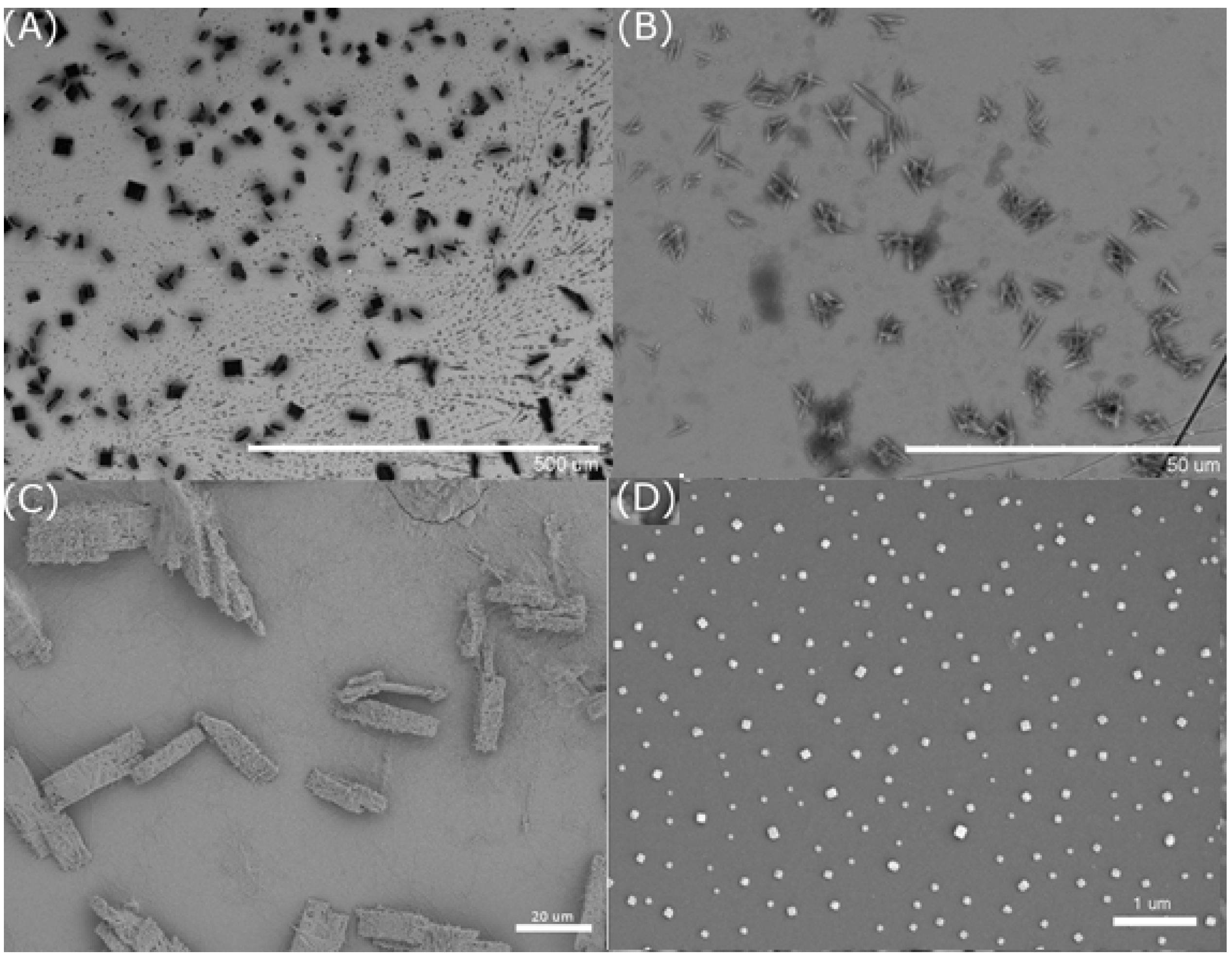
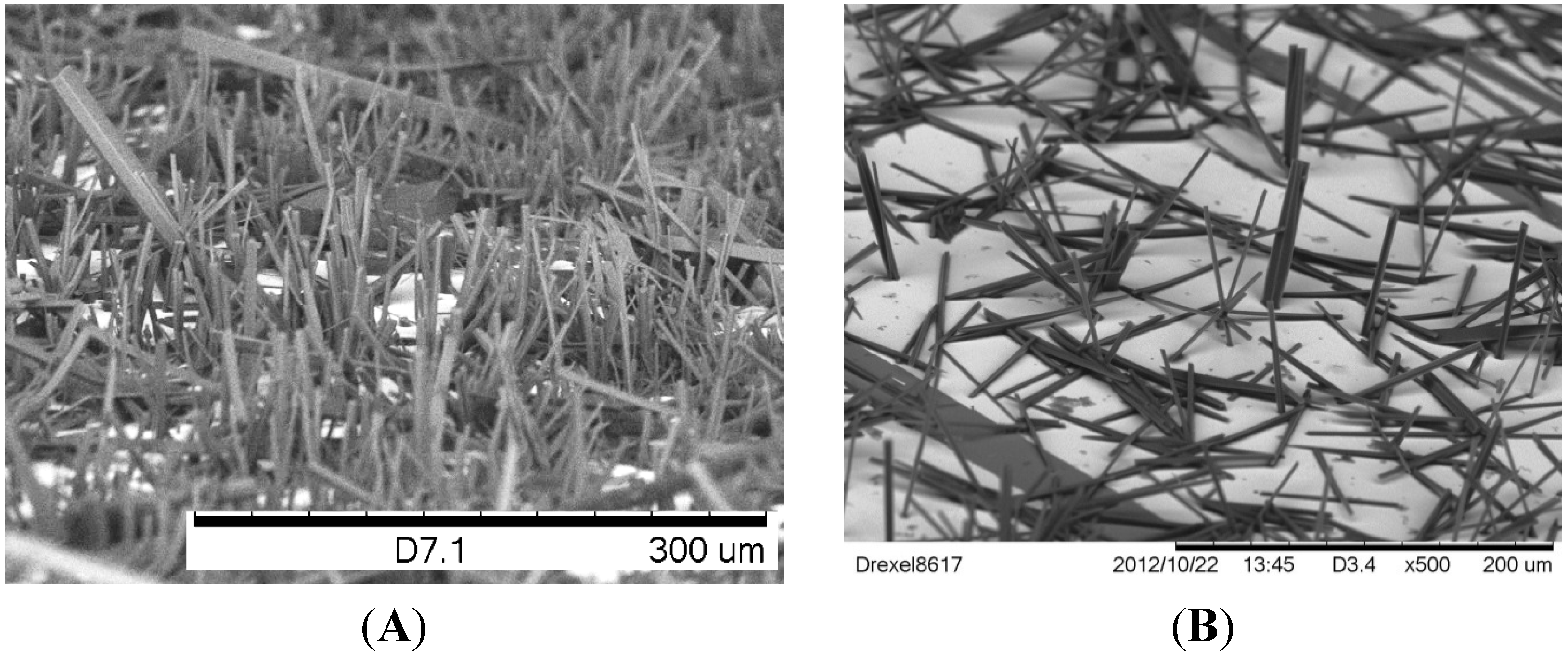
Figure 1 shows the Scanning electron micrographs (SEM) images of Cu(BTC)·3H
2O and Zn(ADC)·DMSO micro/nanopillar arrays on gold surfaces of substrates. The fabrication procedure has been reported in our previous work [
30].
Figure 1.
Scanning electron micrographs (SEM) images of (A) dense Cu(BTC)·3H2O nanopillar array and (B) dense Zn(ADC)·DMSO nanopillars grown on gold substrates. Samples were prepared by mixing a saturated BTC in water or ADC in DMSO solutions along with 30 mM CuSO4·5H2O or 30 mM Zn(NO3)2·6H2O, respectively, in equal volume quantities.
In general, the arrays were prepared by immersing gold coated silicon substrates in solutions that are used for synthesizing MOFs. MOFs form in both solutions and on the surfaces. The morphologies of MOFs on surfaces are most in the form of micro/nanopillars that were vertically oriented on the surface. Typical lengths ranged from 10 to 40 µm and diameters in the nanometer range. As evaporation time is extended to weeks both the diameter and the length of the micropillars increase. A similar result can be achieved by increasing the starting volume of both metal ion and ligand solutions used.
Both MOF systems efficiently produced epitaxial growth of micro/nanopillars on gold substrates. Most Cu(BTC)·3H2O pillars were oriented perpendicular to the plane of the substrate, but most of the Zn(ADC)·DMSO pillars have variable tilt angles.
2.3. XRD of the Micropillars and Nanopillars
Single-crystal data and refinement parameters for both Cu(BTC)·3H
2O and Zn(ADC)·DMSO systems are summarized in
Table 1.
Table 1.
Crystal data and structure refinement for the two metal coordination polymers.
Table 1.
Crystal data and structure refinement for the two metal coordination polymers.
| Condition and Parameter | Cu(BTC)·3H2O | Zn(ADC)·DMSO |
|---|
| Empirical formula | C9H10O9Cu | C19H17SO5Zn |
| Formula weight | 325.71 | 422.76 |
| Temperature (K) | 143(1) | 143(1) |
| Wavelength (Å) | 0.71073 | 0.71073 |
| Crystal system | monoclinic | orthorhombic |
| Space group | P21/n | Pnma |
| a (Å) | 6.7778(7) | 7.3053(7) |
| b (Å) | 18.8206(18) | 17.5056(14) |
| c (Å) | 8.5384(8) | 12.6731(12) |
| β (°) | 92.471(4) | - |
| Volume (Å3) | 1088.16(18) | 1620.7(3) |
| Z | 4 | 4 |
| Density (calculated, Mg/m3) | 1.988 | 1.733 |
| µ (mm-1) | 2.052 | 1.674 |
| F(0 0 0) | 660 | 868 |
| Crystal size | 0.30 × 0.22 × 0.12 mm3 | 0.25 × 0.02 × 0.01 mm3 |
| θ range (°) | 2.16 to 27.53 | 1.98 to 27.53 |
| Index ranges | −8 ≤ h ≤ 8, −24 ≤ k ≤ 24, −11 ≤ l ≤ 11 | −9 ≤ h ≤ 9, −22 ≤ k ≤ 22, −15 ≤ l ≤ 16 |
| Reflections collected | 37602 | 22496 |
| Independent reflections | 2488 (R(int) = 0.0170) | 1929 (R(int) = 0.0557) |
| Completeness to θ = 27.53° | 99.7% | 99.9% |
| Absorption correction | Semi-empirical from equivalents | Semi-empirical from equivalents |
| Max. and min. transmission | 0.7456 and 0.6410 | 0.7456 and 0.6511 |
| Refinement method | Full-matrix least-squares on F2 | Full-matrix least-squares on F2 |
| Data/restraints/parameters | 2488/0/173 | 1929/108/128 |
| Goodness-of-fit on F2 | 1.112 | 1.090 |
| Final R indices (I > 2sigma(I)) | R1 = 0.0194, wR2 = 0.0526 | R1 = 0.0366, wR2 = 0.0894 |
| R indices (all data) | R1 = 0.0196, wR2 = 0.0526 | R1 = 0.0578, wR2 = 0.0996 |
| Largest diff. peak and hole | 0.442 and −0.383 e·Å−3 | 0.970 and −0.660 e·Å−3 |
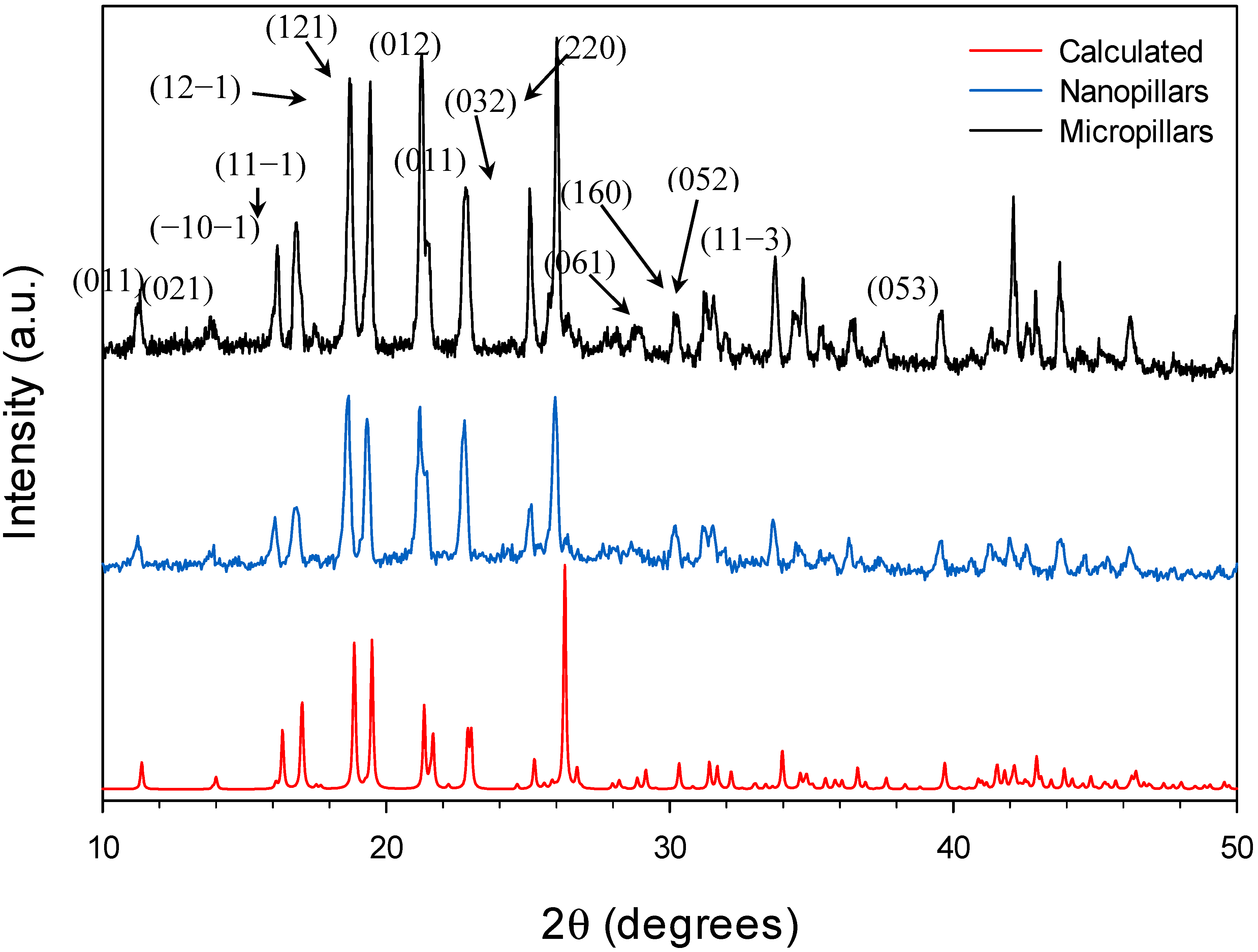
The single crystal XRD study revealed the crystallographic structure of the Cu(BTC)·3H
2O micropillars. However, the crystals of nanopillars are too small to be determined by using single crystal XRD. In order to confirm the structure and crystallinity of the fabricated nanopillars, we performed powder XRD to compare the diffraction patterns of the micropillars and nanopillars, as well as to the calculated pattern of Cu(BTC)·3H
2O. For these experiments, both micro- and nanopillars were prepared in bulk and carefully removed from the gold surfaces for the analyses. Our powder XRD pattern results show strong similarities between the two experimental conditions described in this paper (
Figure 4). In addition, the diffractograms for both crystal sizes are agreeable with the calculated pattern using the structure previously published [
16].
Figure 4.
XRD diffraction patterns of Cu(BTC)·3H2O micropillars and nanopillars, compared to the calculated pattern obtained via Cambridge Crystallographic Data Center (CCDC).
Figure 4.
XRD diffraction patterns of Cu(BTC)·3H2O micropillars and nanopillars, compared to the calculated pattern obtained via Cambridge Crystallographic Data Center (CCDC).
2.4. Thermal Analysis of the MOF Pillars
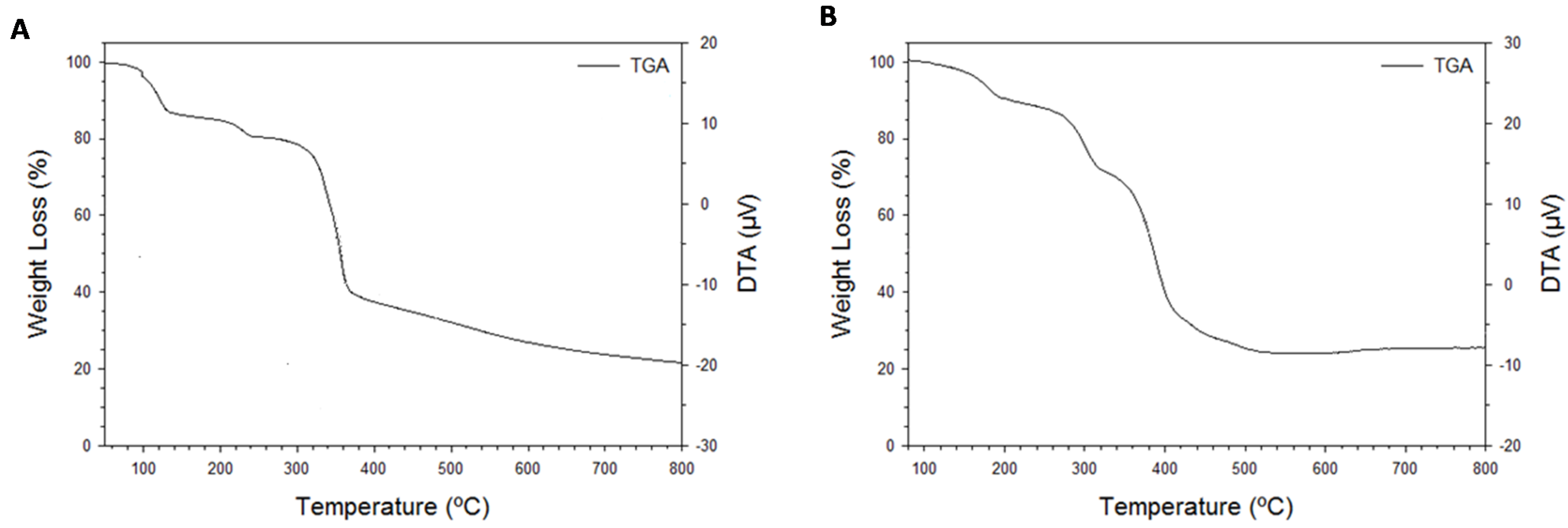
The thermal properties of the metal-coordination polymer nanopillars are shown in
Figure 5. Three weight losses were observed in the thermalgravimetric analysis of Cu(BTC)·3H
2O crystals (
Figure 5A). The onset of the first weight loss occurs at 75 °C, which can be attributed to the release of two out of the three Cu
2+ coordinated water molecules. The loss of the third coordinated water molecule within the structure is removed with an observed weight loss at 205 °C. The observed total weight loss of all three coordinated water molecules is 17.2%, which is agreeable with the calculated percent of water weight loss of 16.5%. The 62.7% weight loss observed at the onset of 270 °C corresponds to the loss of the BTC ligand, which is close to the calculated value of 64.1%. The remaining mass can be attributed to copper metal (calculated 19.4%) and the degraded sample, with an observed percent mass of 20.1% at 800 °C. The weight losses observed correspond to a 3:1:1 ratio between the water molecules, copper metal, and the BTC ligand, respectively. These results are highly agreeable with the crystal structure of the network.
To understand thermal stability of the crystals for future gas absorption studies, thermal analysis was studied. For the Zn(ADC)·DMSO crystals, the thermalgravimetric analysis showed three weight losses (
Figure 5B). The onset of the first mass loss was observed at 120 °C, which would correspond to the loss of DMSO solvent absorbed within the pores of the crystals. The mass loss associated with the loss of absorbed DMSO was found to be approximately 10.0%. The onset of the second loss in mass occurred shortly afterwards with a total mass loss of 14.9%. It is thought that is associated with the loss of DMSO coordinated to Zn
2+ within the coordination network. The onset of the third mass loss occurs at 310 °C, which corresponds to the loss of the ADC ligand (50.4%). The remaining 24.7% mass is mostly due to Zinc metal and degraded carbon in the sample. The calculated ratio of 1:1 for DMSO and ADC, respectively, is agreeable with the crystal structure.
Figure 5.
Thermal gravimetric (TG) analyses of (A) Cu(HBTC)·3H2O and (B) Zn(ADC)·DMSO crystals harvested from gold surfaces after pillared growth.
Figure 5.
Thermal gravimetric (TG) analyses of (A) Cu(HBTC)·3H2O and (B) Zn(ADC)·DMSO crystals harvested from gold surfaces after pillared growth.
2.5. Fluorescence of Zn(ADC)·DMSO Pillars
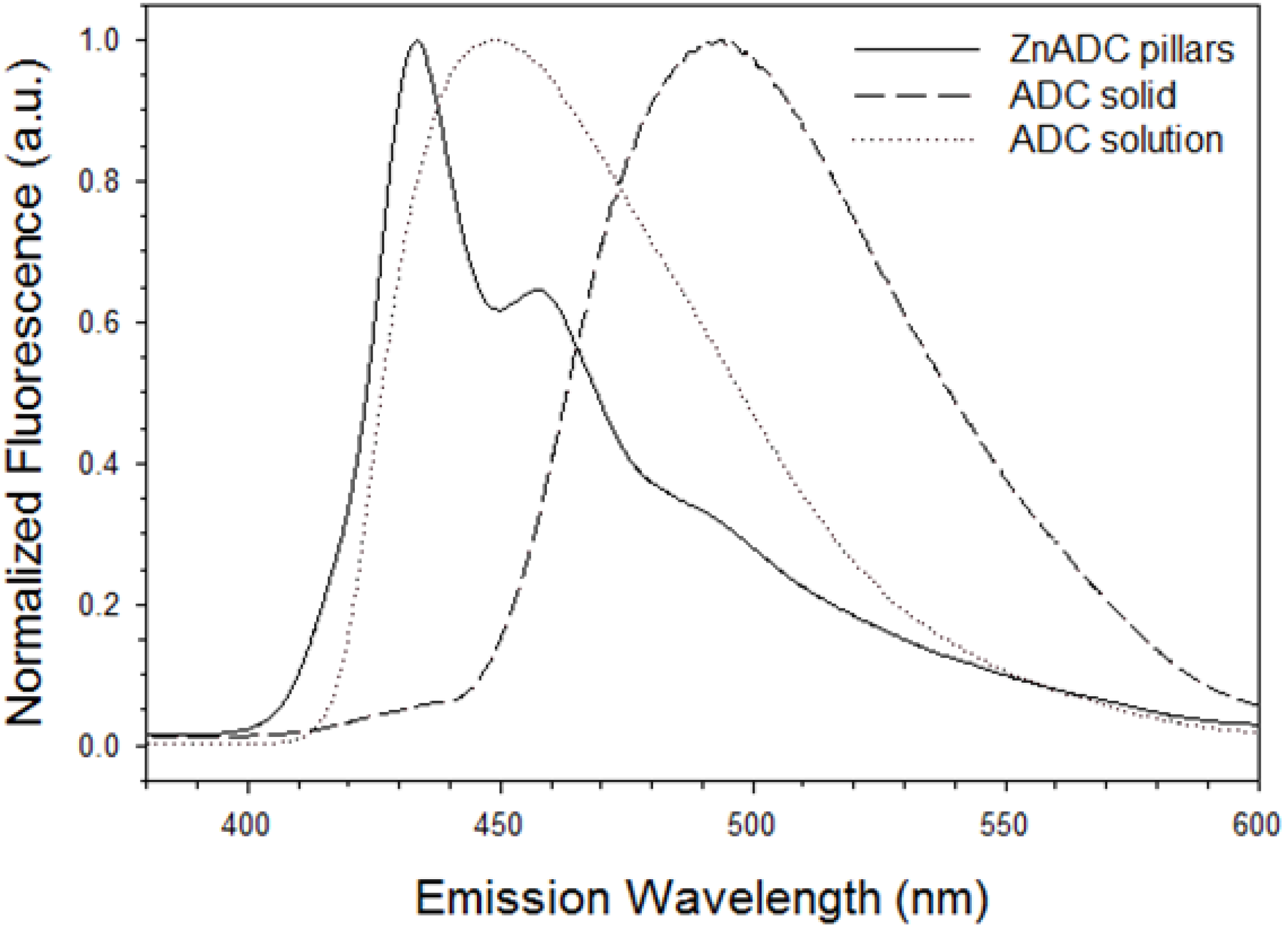
Zn(ADC)·DMSO pillars have a strong blue fluorescence.
Figure 6 shows fluorescence spectra (λ
ex = 320 nm) of Zn(ADC)·DMSO micro/nanopillars, ADC powder, and a 30 mM DMSO solution of ADC. The ADC solid exhibited a far red-shift with an emission maximum at 494 nm, compared to the maxima of the ADC DMSO solution at 448 nm. The peak in the solution is from the ADC monomer. The emission profiles observed in the powder are attributed to the excimer of ADC, which is common for solid state of polyaromatic hydrocarbons [
30,
31,
32]. This 46 nm red-shift from solution to the powder state is attributed to J-aggregation of the anthracene molecules due to π–π stacking [
31].
The emission peaks of Zn(ADC)·DMSO micro/nanowires are at 434 nm and 457 nm. These peaks also belong to the monomer of ADC [
30]; however, with a slight blue-shift. The blue shift is more often due an increase in energy between S
0 and S
1 energy states, which likely arises from the change of the carbonyl resonance by the Zn
2+ ion [
33]. This result is consistent with the observation in XRD,
i.e., no π–π interaction between ADC molecules in ZnADC nanopillars. The aforementioned luminescence results were expected for a MOF system using a fluorescent PAH-based ligand.
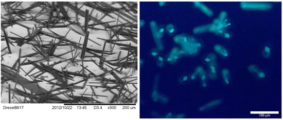
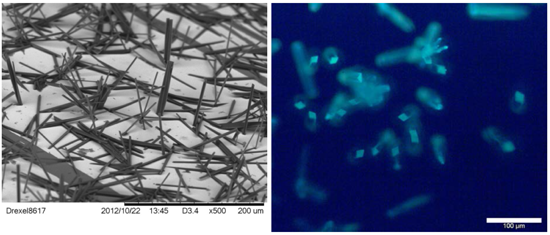
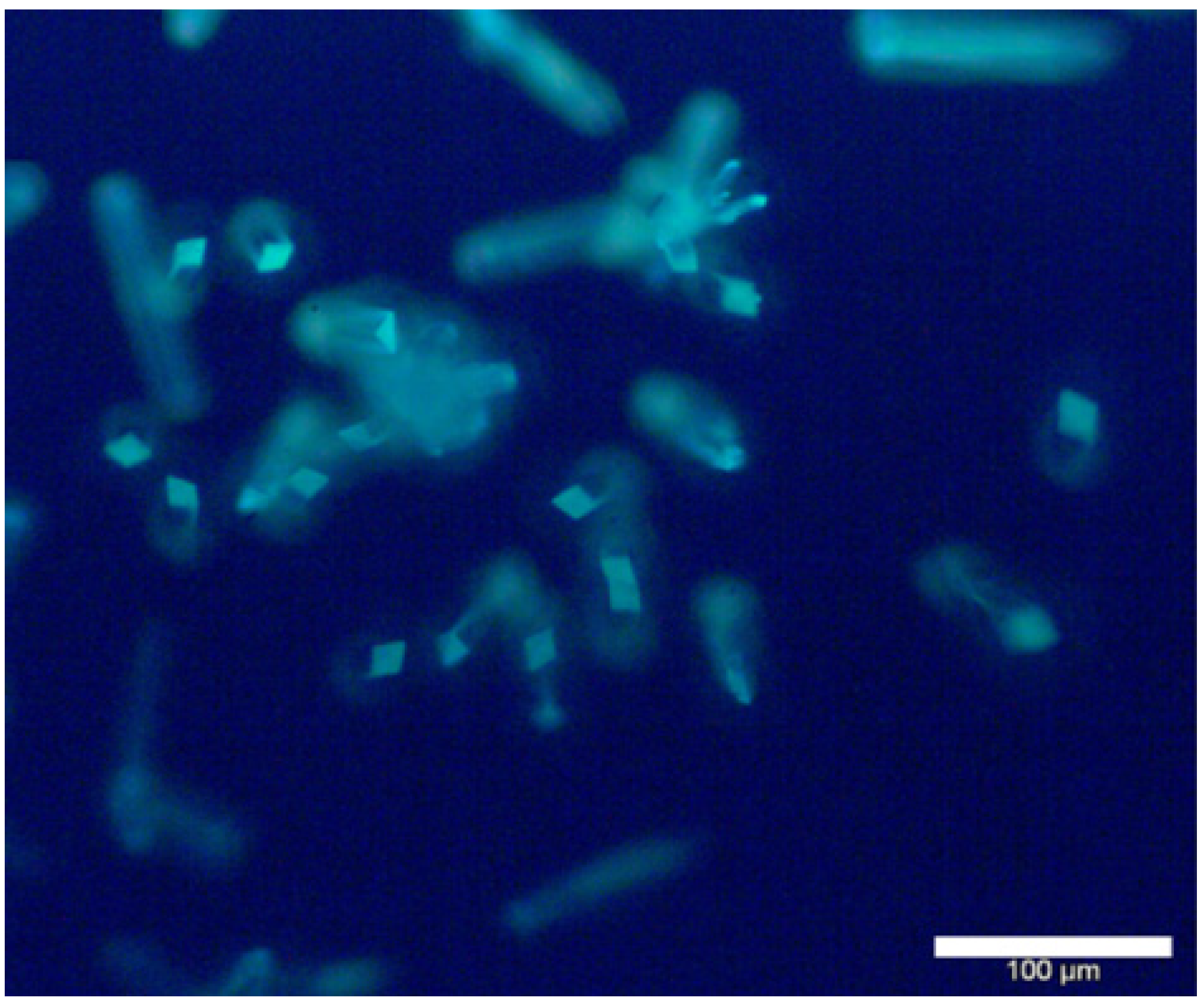
Figure 7 shows a fluorescence microscope image of Zn(ADC)·DMSO micro/nanopillars. Due to the light propagation along the long direction of nano/microwires, the fluorescence of the Zn/ADC nano/microwires is significantly brighter at the end of the wires, which is the outcoupling light resulting from highly oriented molecular arrangement of the crystal [
34], suggesting the Zn/ADC nano/micropillars may be used as a waveguide material for optical applications. The MOF nanopillars prepared in this work can be made in large quantities at a low cost due to the facile self-assembling method.
Figure 6.
Fluorescence emission spectra of Zn(ADC)·DMSO and 9,10-anthracenedicarboxylic acid using solid-state and solution (λex = 320 nm).
Figure 6.
Fluorescence emission spectra of Zn(ADC)·DMSO and 9,10-anthracenedicarboxylic acid using solid-state and solution (λex = 320 nm).
Figure 7.
Fluorescence microscope image of Zn(ADC)·DMSO micro/nanopillars.
Figure 7.
Fluorescence microscope image of Zn(ADC)·DMSO micro/nanopillars.
3. Experimental Section
CuSO4·5H2O (Fisher Scientific), Zn(NO3)2·6H2O (Baker Chemical), 1,3,5-benzenetricarboxylic acid (BTC, Alfa Aesar, Ward Hill, MA, USA), 9,10-anthracenedicarboxylic acid (ADC, Sigma Aldrich, St. Louis, MO, USA), and solvents methanol and dimethyl sulfoxide (Reagent/ACS grade, Pharmco-AAPER, Brookfield, CT, USA) were used as received. Thin-film gold substrates were prepared by e-beam evaporation (BOC Edwards, Crawley, UK). 150 mm-diameter test silicon wafers (Wacker Silicone, Munich, Germany) were coated with a 3 nm thin film of chromium, followed by a 20 nm-thick deposition of gold. Prior to use, substrates were gently rinsed with deionized water and methanol, followed by treatment with UV/ozone (Bioforce ProCleaner, Ames, IA, USA) for 20 min.
Solid state and solution fluorescence spectra were obtained by using a Hitachi F-7000 fluorescence spectrophotometer using an excitation wavelength (λex) of 320 nm with both the excitation and emission slit width at 5.0 nm. Fluorescence and optical microscopy images were taken using an Olympus BX51 microscope with an Olympus U-RFL-T Mercury burner. ATR infrared spectra were recorded using a Smiths IlluminatIR microscope. Thermal analyses were conducted using a thermogravimeter/differential thermal analyzer (TG/DTA 6300, SII Nanotechnology, Tokyo, Japan) using a heating rate of 10 °C·min−1 with a regulated nitrogen gas flow of 50 cm3·min−1. Scanning electron micrographs (SEM) were obtained using a Hitachi Tabletop Microscope (TM-1000) and Zeiss Supra 50VP with Oxford energy-dispersive X-ray detection (EDX). Micrographs obtained using the Zeiss Supra 50VP were obtained using the SE2 Inlens. Crystallographic data was collected using a Bruker Kappa APEX II Duo CCD diffractometer. Structure solution and refinement was performed using Bruker’s SHELXTL package. Powder X-ray diffraction (XRD) patterns were obtained using a Rigaku Smartlab diffractometer using CuKα1 radiation in Bragg-Brentano focusing and Debye-Scherrer geometry. Calculated XRD patterns were obtained using the Mercury crystal visualization software package. Crystal structure files were obtained from the Cambridge Crystallographic Data Center (CCDC).
4. Conclusions
Crystalline micro/nanowires of Cu(BTC)·3H2O and Zn(ADC)·DMSO were characterized in this work. The facile approach for micro/nanopillar synthesis allows rapid pillared growth with high crystallinity of the MOF systems presented. The MOF micro/nanopillars may have controllable interconnection of the electronic and optoelectronic devices through a vertical integration process using no lithography. This process is low cost and can be high throughput, and offers significant advantages over other methods to prepare nanowire based devices.
Acknowledge
This work was supported from the National Science Foundation (No. DMR-1104835) and the Drexel-SARI Grant.
Author Contributions
Arben Kojtari did all the experiments and wrote the paper draft. Hai-Feng Ji advised the work and modified the MS.
Conflicts of Interest
The authors declare no conflict of interest.
References
- Delgado-Friedrichs, O.; O’Keeffe, M.; Yaghi, O.M. Taxonomy of periodic nets and the design of materials. Phys. Chem. Chem. Phys. 2007, 9, 1035–1043. [Google Scholar]
- Kuppler, R.J.; Timmons, D.J.; Fang, Q.-R.; Li, J.-R.; Makal, T.A.; Young, M.D.; Yuan, D.; Zhao, D.; Zhuang, W.; Zhou, H.-C. Potential applications of metal-organic frameworks. Coord. Chem. Rev. 2009, 253, 3042–3066. [Google Scholar]
- Banerjee, R.; Phan, A.; Wang, B.; Knobler, C.; Furukawa, H.; O’Keeffe, M.; Yaghi, O.M. High-throughput synthesis of zeolitic imidazolate frameworks and application to CO2 capture. Science 2008, 319, 939–943. [Google Scholar]
- Sumida, K.; Horike, S.; Kaye, S.S.; Herm, Z.R.; Queen, W.L.; Brown, C.M.; Grandjean, F.; Long, G.J.; Dailly, A.; Long, J.R. Hydrogen storage and carbon dioxide capture in an iron-based sodalite-type metal–organic framework (Fe-BTT) discovered via high-throughput methods. Chem. Sci. 2010, 1, 184–191. [Google Scholar]
- McKinlay, A.C.; Morris, R.E.; Horcajada, P.; Férey, G.; Gref, R.; Couvreur, P.; Serre, C. BioMOFs: Metal-organic frameworks for biological and medical applications. Angew. Chem. Int. Ed. Engl. 2010, 49, 6260–6266. [Google Scholar]
- Lee, J.; Farha, O.K.; Roberts, J.; Scheidt, K.; Nguyen, S.T.; Hupp, J.T. Metal–organic framework materials as catalysts. Chem. Soc. Rev. 2009, 38, 1450–1459. [Google Scholar]
- Robinson, D.M.; Go, Y.B.; Mui, M.; Gardner, G.; Zhang, Z.; Mastrogiovanni, D.; Garfunkel, E.; Li, J.; Greenblatt, M.; Dismukes, G.C. Photochemical water oxidation by crystalline polymorphs of manganese oxides: Structural requirements for catalysis. J. Am. Chem. Soc. 2013, 135, 3494–3501. [Google Scholar]
- Sumida, K.; Rogow, D.L.; Mason, J.A.; McDonald, T.M.; Bloch, E.D.; Herm, Z.R.; Bae, T.-H.; Long, J.R. Carbon dioxide capture in metal–organic frameworks. Chem. Rev. 2012, 112, 724–781. [Google Scholar]
- Bradshaw, D.; Garai, A.; Huo, J. Metal–organic framework growth at functional interfaces: Thin films and composites for diverse applications. J. Chem. Soc. Rev. 2012, 41, 2344–2381. [Google Scholar]
- Huang, A.; Bux, H.; Steinbach, F.; Caro, J. Molecular-sieve membrane with hydrogen permselectivity: ZIF-22 in LTA topology prepared with 3-aminopropyltriethoxysilane as covalent linker. Angew. Chem. Int. Ed. Engl. 2010, 49, 4958–4961. [Google Scholar]
- Xu, G.; Yamada, T.; Otsubo, K.; Sakaida, S.; Kitagawa, H. Facile “modular assembly” for fast construction of a highly oriented crystalline MOF nanofilm. J. Am. Chem. Soc. 2012, 134, 16524–16527. [Google Scholar]
- Liu, N.; Yao, Y.; Cha, J.J.; McDowell, M.T.; Han, Y.; Cui, Y. Functionalization of silicon nanowire surfaces with metal–organic frameworks. Nano Res. 2011, 5, 109–116. [Google Scholar]
- Zhuang, J.; Friedel, J.; Terfort, A. The oriented and patterned growth of fluorescent metal–organic frameworks onto functionalized surfaces. Beilstein J. Nanotechnol. 2012, 3, 570–578. [Google Scholar]
- Carbonell, C.; Imaz, I.; Maspoch, D. Single-crystal metal−organic framework arrays. J. Am. Chem. Soc. 2011, 133, 2144–2147. [Google Scholar]
- Hu, S.-M.; Niu, H.-L.; Qiu, L.-G.; Yuan, Y.-P.; Jiang, X.; Xie, A.-J.; Shen, Y.-H.; Zhu, J.-F. Design, synthesis and characterization of a modular bridging ligand platform for bio-inspired hydrogen production. Inorg. Chem. Commun. 2012, 17, 147–150. [Google Scholar]
- Kojtari, A.; Carrol, P.; Ji, H.-F. Metal organic framework (MOF) micro/nanopillars. Cryst. Eng. Comm. 2014, 16, 2885–2888. [Google Scholar]
- Chandra, D.; Yang, S. Stability of high-aspect-ratio micropillar arrays against adhesive and capillary forces. Acc. Chem. Res. 2010, 43, 1080–1091. [Google Scholar]
- Xie, C.; Hanson, L.; Cui, Y.; Cui, B. Vertical nanopillars for highly localized fluorescence imaging. Proc. Natl. Acad. Sci. USA 2011, 108, 3894–3899. [Google Scholar]
- Li, X.; Li, J.; Chen, T.; Tay, B.K.; Wang, J.; Yu, H. Periodically aligned Si nanopillar arrays as efficient antireflection layers for solar cell applications. Nanoscale Res. Lett. 2010, 5, 1721–1726. [Google Scholar]
- Fan, Z.; Kapadia, R.; Leu, P.W.; Zhang, X.; Chueh, Y.-L.; Takei, K.; Yu, K.; Jamshidi, A.; Rathore, A.A.; Ruebusch, D.J.; et al. Ordered arrays of dual-diameter nanopillars for maximized optical absorption. Nano Lett. 2010, 10, 3823–3827. [Google Scholar]
- Ji, L.; Tan, Z.; Kuykendall, T.; An, E.J.; Fu, Y.; Battaglia, V.; Zhang, Y. Multilayer nanoassembly of Sn-nanopillar arrays sandwiched between graphene layers for high-capacity lithium storage. Energy Environ. Sci. 2011, 4, 3611–3616. [Google Scholar]
- Lo, M.-H.; Cheng, Y.-J.; Kuo, H.-C.; Wang, S.-C. Enhanced stimulated emission from optically pumped gallium nitride nanopillars. Appl. Phys. Express 2011, 4. [Google Scholar] [CrossRef]
- Chen, K.J.; Hung, F.Y.; Chang, S.J.; Young, S.J. Optoelectronic characteristics of UV photodetector based on ZnO nanopillar thin films prepared by sol-gel method. Mater. Trans. 2009, 50, 922–925. [Google Scholar]
- Santos, A.; Formentín, P.; Pallarés, J.; Ferré-Borrull, J.; Marsal, L.F. Fabrication and characterization of high-density arrays of P3HT nanopillars on ITO/glass substrates. Sol. Energy Mater. Sol. Cells 2010, 94, 1247–1253. [Google Scholar]
- Jeon, D.-W.; Choi, W.M.; Shin, H.-J.; Yoon, S.-M.; Choi, J.-Y.; Jang, L.-W.; Lee, I.-H. Nanopillar InGaN/GaN light emitting diodes integrated with homogeneous multilayer graphene electrodes. J. Mater. Chem. 2011, 21, 17688–17692. [Google Scholar]
- Caldwell, J.D.; Glembocki, O.; Bezares, F.J.; Bassim, N.D.; Rendell, R.W.; Feygelson, M.; Ukaegbu, M.; Kasica, R.; Shirey, L.; Hosten, C.; et al. Plasmonic nanopillar arrays for large-area, high-enhancement surface-enhanced raman scattering sensors. ACS Nano 2011, 4046–4055. [Google Scholar]
- Shalek, A.K.; Robinson, J.T.; Karp, E.S.; Lee, J.S.; Ahn, D.-R.; Yoon, M.-H.; Sutton, A.; Jorgolli, M.; Gertner, R.S.; Gujral, T.S.; et al. Vertical silicon nanowires as a universal platform for delivering biomolecules into living cells. Proc. Natl. Acad. Sci. USA. 2010, 107, 1870–1875. [Google Scholar]
- Shin, C.; Shin, W.; Hong, H.-G. Electrochemical fabrication and electrocatalytic characteristics studies of gold nanopillar array electrode (AuNPE) for development of a novel electrochemical sensor. Electrochim. Acta 2007, 53, 720–728. [Google Scholar]
- Zaera, F. Nanostructured materials for applications in heterogeneous catalysis. Chem. Soc. Rev. 2012, 42, 2746–2762. [Google Scholar]
- Mizobe, Y.; Miyata, M.; Hisaki, I.; Hasegawa, Y.; Tohnai, N. Anomalous anthracene arrangement and rare excimer emission in the solid state: Transcription and translation of molecular information. Org. Lett. 2006, 8, 4295–4298. [Google Scholar]
- Dong, Y.; Xu, B.; Zhang, J.; Tan, X.; Wang, L.; Chen, J.; Lv, H.; Wen, S.; Li, B.; Ye, L.; et al. Piezochromic luminescence based on the molecular aggregation of 9,10-bis((E)-2-(pyrid-2-yl)vinyl)anthracene. Angew. Chem. Int. Ed. Engl. 2012, 51, 10782–10785. [Google Scholar]
- Abdel-Mottaleb, M.S.A.; Galal, H.R.; Dessouky, A.F.M.; El-Naggar, M.; Mekkawi, D.; Ali, S.S.; Attya, G.M. Fluorescence and photostability studies of anthracene-9-carboxylic acid in different media. Int. J. Photoenergy 2000, 2, 47–53. [Google Scholar]
- Kim, H.S.; Bae, C.O.; Kwon, J.Y.; Kim, S.K.; Choi, M.W.; Yoon, J.Y. Study on the fluorescence of 1,8-anthracenedicarboxylic acid and 1,8-anthracenediformamide. Bull. Korean Chem. Soc. 2001, 22, 929–931. [Google Scholar]
- Balzer, F.; Bordo, V.G.; Simonsen, A.C.; Rubahn, H.-G. Isolated hexaphenyl nanofibers as optical waveguides. Appl. Phys. Lett. 2003, 82, 10–12. [Google Scholar]
© 2015 by the authors; licensee MDPI, Basel, Switzerland. This article is an open access article distributed under the terms and conditions of the Creative Commons Attribution license (http://creativecommons.org/licenses/by/4.0/).


