2.1. Nacre
One of the most studied natural materials in the field of biomimetics is nacre which is the mother-of-pearl found inside many seashells
. Nacre is an especially interesting material for study because it is composed of 95% calcium carbonate, in the form of aragonite, layered with 5% of polymeric organic matter, and yet it has a fracture strength of about 3000 times pure calcium carbonate [
1]. The nature of this improvement in mechanical strength is related to nacre’s unique microstructure and yields many suggestions for how to improve man-made materials. While the strength of a composite can be improved by striving for stronger individual components, nacre stands as an example of how careful placement of weaker materials can yield similar results. It has also been pointed out that nacre has many characteristics that are desirable in biomedical materials. The many components of nacre have a hierarchical organization, mild processing conditions, simple constituents, durable interfaces, viscoelastic properties, good fatigue performance, and some extent of self-healing [
2]. Incorporating these qualities in biomaterials is therefore a desirable goal and careful study of nacre’s structure and formation can help achieve it.
In nacre, the calcium carbonate is present as aragonite tablets of about 5 µm across and 0.5 µm thick [
2]. These tablets can then be further sectioned as numerous nanograins of approximately 10–50 nm in diameter held together by an organic matrix [
2]. Individual aragonite platelets grow between polymer sheets in the organic matrix via the assembly of nanoparticles nucleated from colloidal amorphous calcium carbonate [
3,
4]. These nanograins are capable of many of the same deformation behaviors observed to occur between the constituent tablets on the microscale such as deformation and rotation [
3]. Natural nacre is structured in two different forms: columnar and sheet, which are distinguished based on the orientation of the centers of successive platelets stacked on top of one another, and are located in the shell for optimal performance [
5]. In both forms, there are layers about 300 µm thick composed of sublayers of aragonite platelets which are separated by organic layers of 20–50 nm [
6]. These 300 µm platelet layers are separated by thicker 20 µm mesolayers of multiple organic layers [
2]. The thick mesolayers are a result of seasonal effects as changes in the feeding patterns limit available ions for mineral formation [
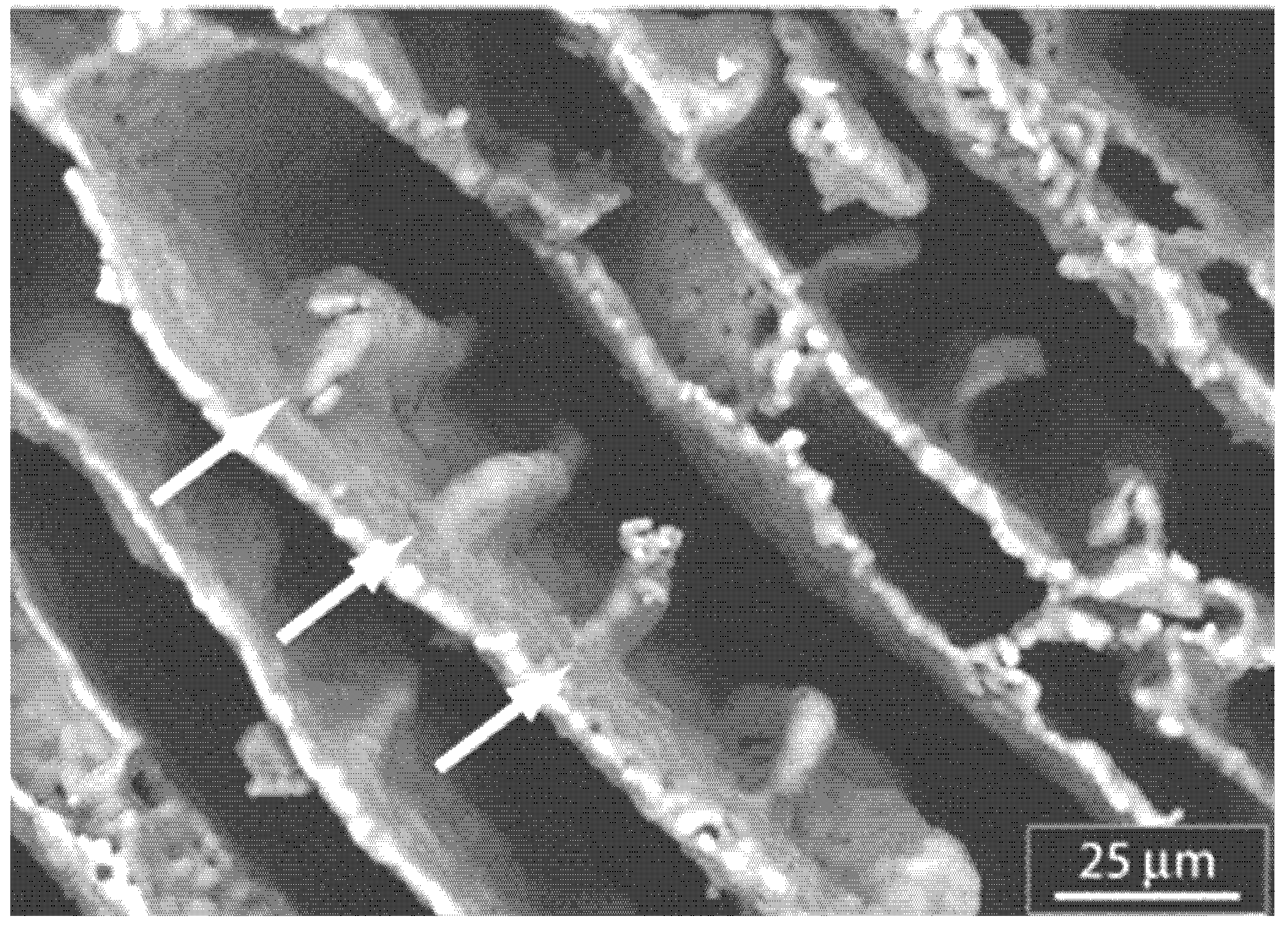
4]. Within each aragonite layer, there are large domains of platelets which have the same crystallographic orientation (
Figure 1) [
1].
Figure 1.
SEM image showing that the imprints of nano-asperity grooves correspond to the crystal directions of the aragonite platelets. Reproduced from [
2] with permission from The Royal Society.
Figure 1.
SEM image showing that the imprints of nano-asperity grooves correspond to the crystal directions of the aragonite platelets. Reproduced from [
2] with permission from The Royal Society.
This alignment between platelets is also preserved in the vertical direction as proved by identical pole figures at 5 and 10 degrees, which corresponds to a depth of 5–11 µm or up to 20 platelet layers [
2]. Yao
et al. has proposed that these aragonite layers grow via a spiral helix propagation model which explains the large-scale alignment of the platelets in both the lateral and vertical directions [
2]. The sources of these helices are growth fronts which are anchored by paired screw dislocations on each end to form an extended line defect with a thickness of one platelet layer [
2].
The characteristics of these aragonite platelets are only part of the explanation of why nacre is so impressive. It is also important to consider the mechanical and chemical properties of the organic material in the shells. The organic mesolayers are made of about 7% oriented beta-chitin fibrils, which are silk-like proteins organized into sheets [
7]. These have been found to extend over multiple platelets and is constructed of individual chitin fibers of lengths of at least1µm linked into a network by proteins [
7]. These fibrils are then surrounded by about 75% proteins, including lustrinA which is composed of many sacrificial loops that can be extended during stress periods [
5,
7]. Since these loops are created through the van der Waals association of hydrophilic or hydrophobic domains, new loops can be formed after deformation to restore some of the mechanical properties [
8]. The interfaces between the tablets and organic layer are anchored assemblies of peptide chains, mostly amino acids with carboxylic groups [
9]. Finally, the organic material is found even within the platelets themselves in the form of discontinuous layers of aspartic acid-rich glycoproteins called the “intratabular matrix” [
7,
9].
The organic matrix performs many roles in the shell and recently it has been posited that the organic layer does more to organize the material structure than the inorganic. Organic layers are laid down by the abalone with a regular frequency such that tablets sandwiched between them can grow only until their height is arrested. However, growth can still occur laterally within this layer as material passes through organic pores until all the space has been filled [
10]. This material probably passes to the tablet in the form of ions or amorphous calcium carbonate [
11]. As noted before, large domains of similarly oriented crystals are common in both the vertical and horizontal direction. A long-standing question has therefore been how this orientation is transferred from one platelet to another in the absence of crystal continuity. Wise and deVilliers hypothesized that the organic layer was in fact oriented by the platelets over which it was deposited [
12]. This in turn could explain how crystal orientation is then transferred again to the platelets that grow overtop of it. However, other authors have recently suggested that the organic layer is disordered and tablets may pass crystallographic material from one layer to the next in order to maintain this orientation either through crystalline continuities or as amorphous calcium carbonate. However, before we can compare these theories, we need an understanding of how the organic layer functions.
While this explains what nacre is composed of, it does not explain its impressive mechanical strength. An individual aragonite tablet has a mechanical strength approximately the same as that of pure calcium carbonate [
8], so what about nacre gives the notable improvement? First, consider the effect of aragonite nanograins and platelets on the shell’s deformation. Cross-sections of nacre show that the platelets and organic matrix are arranged in a “brick-and-mortar” pattern. This severely limits the ability of any crack to propagate perpendicular to these layers; it will quickly run directly into one of the tablets. Not only are these tablets strong due to the innate material characteristics, but the dimensions of the platelets are such that they ensure optimum strength and flaw tolerance [
9,
11,
13]. The edges of the tablets are slightly thicker than the center so that as the tablets try to slide past one another, they find it increasingly difficult to move due to the difficulties of shifting all the surrounding platelets out of formation and will become locked together [
8]. However, under tension, failure of the aragonite layer will occur through tablet pull-out and relies on the organic layer for durability [
5,
11]. At the platelet level, Sumitomo
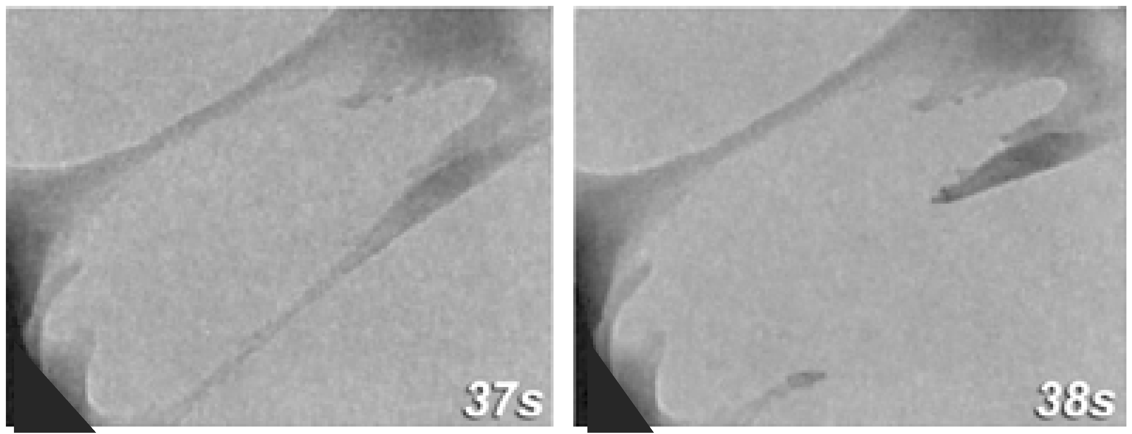
et al., found that the organic matrix could stretch into ligaments that would reach 460 nm before rupturing and the two broken ligament ends would then densify with reformation (
Figure 2) [
8]. The organic material is less likely to pull away from the tablet because the lustrinA present in the system adheres the chitin cores to the mineral tablets [
11]. By measuring the force-extension behavior of the organic material, they found that it matched the behavior expected for the reversible unfolding of modular domains and sacrificial bonds [
2].
Organic ligaments can be seen bridging the gap between separated platelets as well as between the nanograins of fractured platelets [
3]. In the case of the nanograins, there is a high degree of overlap and the organic matrix is at most 10 nm thick [
3]. This organic material can stretch to 40 nm before failure and probably occurs in the platelet because it was trapped between nucleating nanograins during crystallization [
3].
Figure 2.
TEM still image sequence showing
in situ deformation of organic matrix between plates with the time intervals shown in seconds. Adhesion at the wall is strong and failure will occur by deformation of the ligament. The recoiling broken strand shows densification at its base. Reproduced from [
8] with permission from Cambridge University Press.
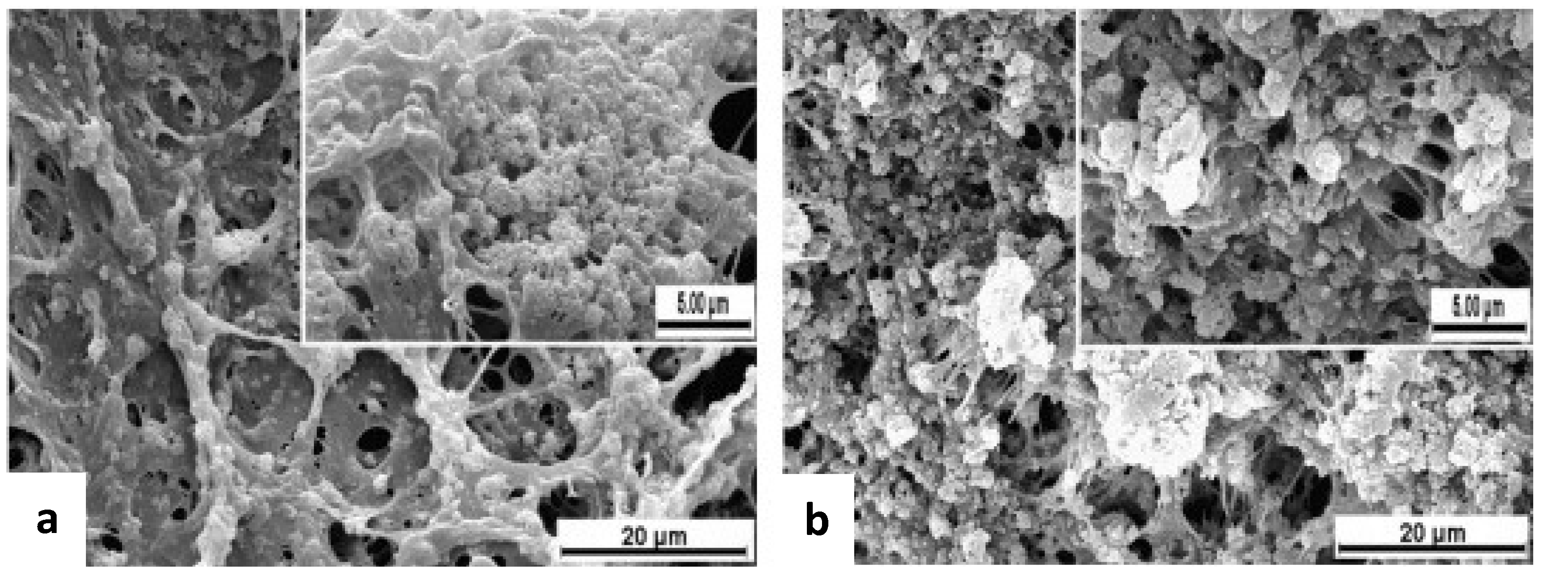
It has been proposed that individual platelets could also interact in other ways to prevent deformation including shear resistance from the asperities, mineral bridges that dissipate energy by cracking, and crack-tip shielding due to the integration of two materials with different elastic moduli [
9]. The shear resistance from asperities and interlocks has been modeled by using finite elements by Katti (
Figure 3), who proved that these were the dominating sources of friction for the interface and also acted to prevent catastrophic failure [
2].
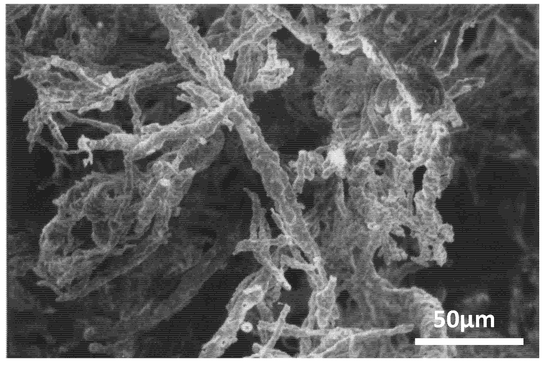
Figure 3.
SEM image of a fractured nacre surface showing presence of interlocking between platelets of nacre responsible for its mechanical response. Reproduced from [
14] with permission from Elsevier.
Figure 3.
SEM image of a fractured nacre surface showing presence of interlocking between platelets of nacre responsible for its mechanical response. Reproduced from [
14] with permission from Elsevier.
Interlocks were estimated to reach a depth of 50 nm (20 nm of which constituted the organic separating layer) and created by adjacent platelets being rotated approximately 5 degrees with respect to one another [
14]. Katti’s simulation found that nacre without interlocks had a yield stress of 5 MPa but nacre with interlocks had a yield stress of 37 MPa, and therefore concluded that interlocks are an essential part of nacre’s toughening mechanism [
14]. By performing indentation tests, Katti’s group also found that the hardness and elastic modulus values decrease with increasing load [
15]. They attribute this to crack propagation as the different loads will engage the organic and inorganic material to different degrees [
15].
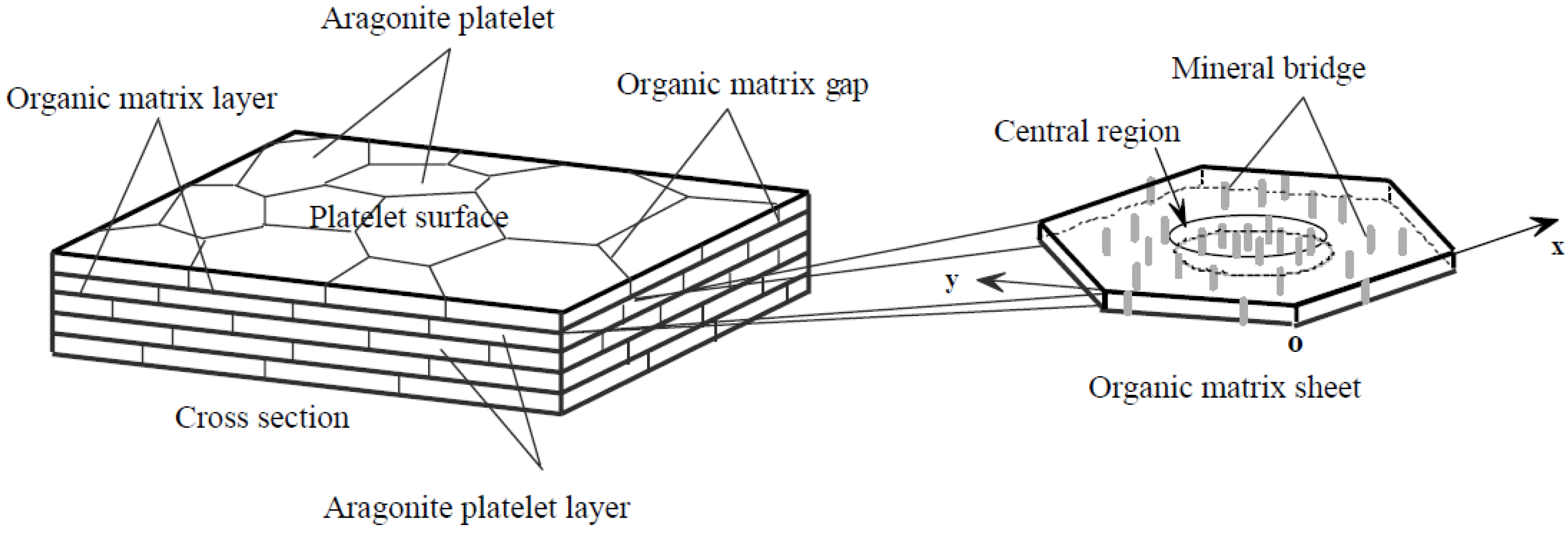
Mineral bridges are often cited as a logical source of resistance to shear forces because they would require an energy input sufficient to crack them before platelets can slide past one another. These are discussed in detail by Song
et al., who describe the existence of nanopores in the organic matrix and attribute them to the presence of mineral bridges (
Figure 4). While these pores are more likely due to jutting nanoasperities on the platelet surfaces, they still are one possible explanation for how crystallographic information is transferred from one layer to the next [
2].
Figure 4.
Schematic illustration showing the “brick and mortar” microarchitecture of nacre; the mineral bridges in an organic matrix sheet. While we are considering the mineral bridges to in fact be nanoasperities, the image shows the pores in the organic layer and therefore the arrangement of these nanoasperities. Reproduced from [
16] with permission from Elsevier.
These nano-pores were also found to cluster in the center of platelets and be sparser on the edges; this greatly improves nacre’s ability to deflect cracks. Instead of cracks being allowed to propagate in the organic matrix layer, which would delaminate the platelets, it will propagate in the matrix layer only until it reaches the nanoasperities before being deflected and traveling down the next organic matrix gap [
16]. This allows the organic layer to adsorb much of the incoming energy and will minimize the degree of deformation. While Song
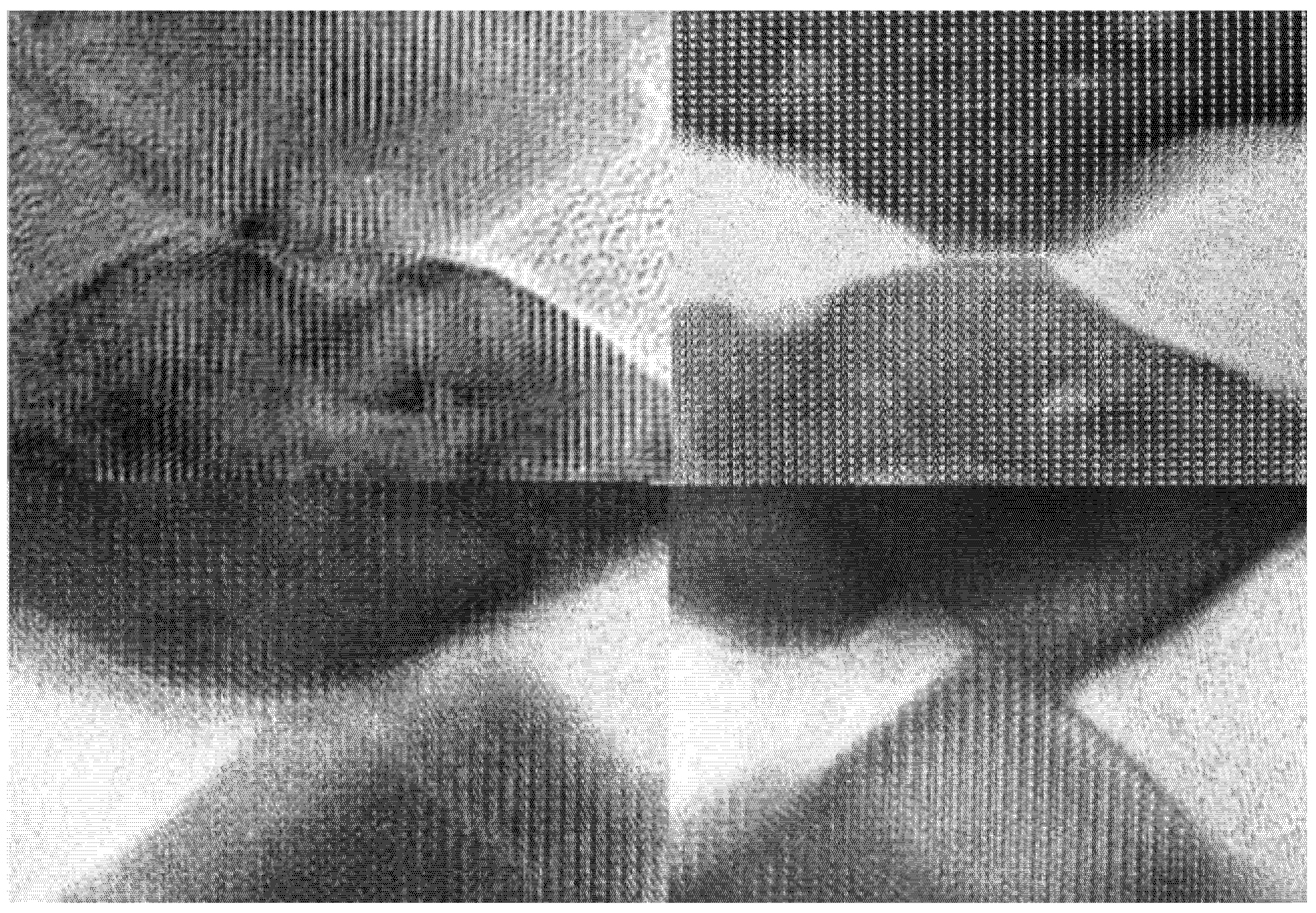
et al.’s findings regarding nanopores and subsequent predictions about crack propagation still hold true, new research has shown that these “mineral bridges” are not in fact continuous. Yao
et al. used transmission electron microscopy to prove that the bridges that had been previously referenced were in fact abutting asperities and not continuous crystal bridges (
Figure 5) [
2]. This was confirmed by Checa
et al., who found that what appear to be mineral bridges are simply overlapping crystal extrusions through large pores in the organic matrix [
17].
Therefore, while energy would be required to shift the nanoasperities past one another, the movement will require less than if breaking a mineral bridge was required. To sum these contributions, Lin and Meyers measured the shear strength of the interface between platelets to be about 50 MPa with an average maximum shear strain of 0.3 [
6]. Wang
et al. have done the same for compression and tensile testing. For compression, they found a stress of 370 MPa and a strain of 0.005 [
5]. For tensile testing, the stress was measured to be 105 MPa and the strain as 0.011 [
5]. These tests can be interpreted give an idea of nacre’s behavior in under each condition and emphasizes the importance of the organic-inorganic interactions. These behaviors have also been replicated in simulations by Tang
et al. [
18]. In the case of shear, nacre initially demonstrates elastic deformation which is a contribution from the organic material, before transitioning to inelastic deformation as the nanoasperities and interlocks are forced past one another (
Figure 6). In compression, there is at first elastic deformation as the organic layers are squeezed to their full extent before it seems the platelets are unrecoverably forced apart. Finally, under tension the nacre behaves inelastically as dilation bands form and the platelets are pulled apart.
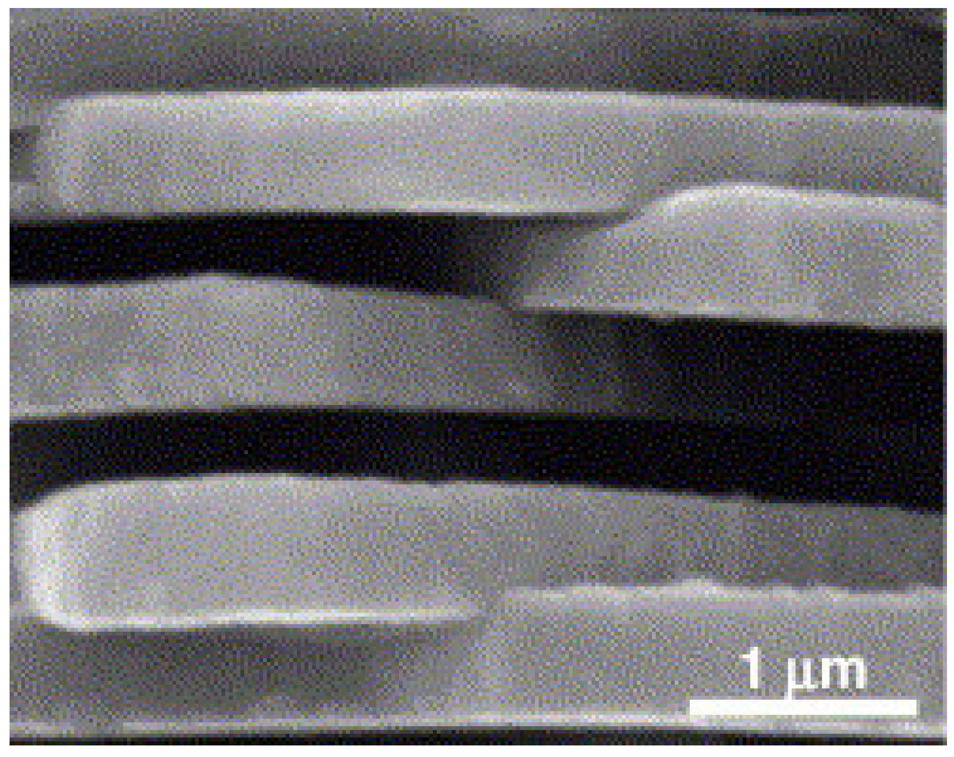
Figure 5.
Demonstrates that crystal outgrowths of nano-asperities from the top and bottom platelets are not exactly connected or epitaxial, even though they share the same crystal orientation as indicated by atomic lattice alignments. Reproduced from [
2] with permission from The Royal Society.
Figure 5.
Demonstrates that crystal outgrowths of nano-asperities from the top and bottom platelets are not exactly connected or epitaxial, even though they share the same crystal orientation as indicated by atomic lattice alignments. Reproduced from [
2] with permission from The Royal Society.
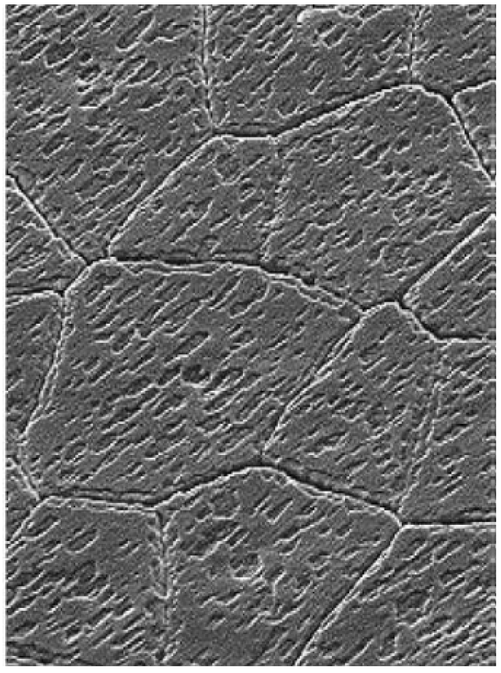
Figure 6.
Cross-section of abalone nacre showing the detailed structure at the lamellae boundaries with arrows to highlight some of the locations where nanoasperities interpose. As the platelets shift past one another, the energy to move these nanoasperities over each other will contribute to the dissipation of energy. Reproduced from [
5] with permission from Cambridge University Press.
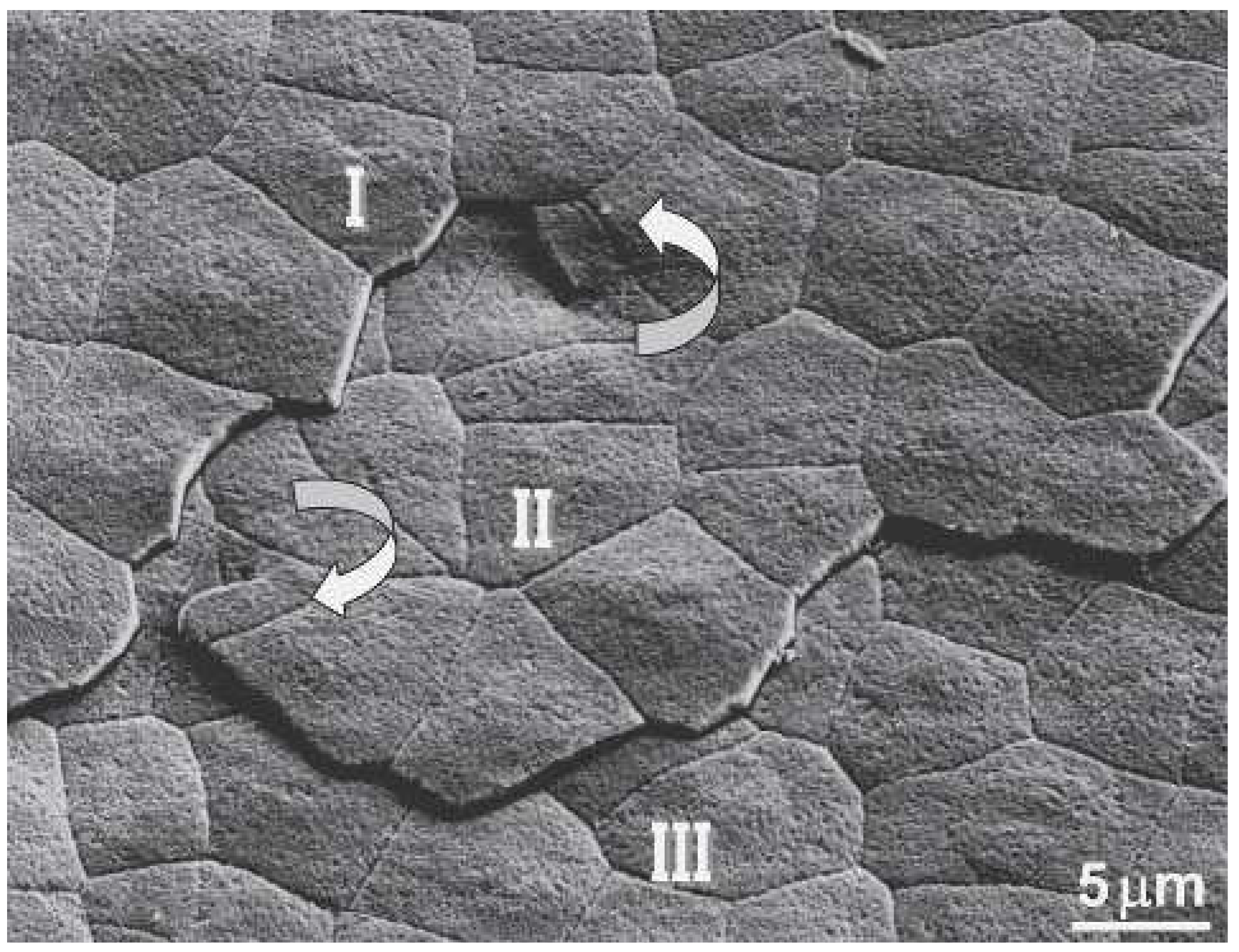
To further investigate the benefits of this phenomenon, Yao
et al. used a nanomanipulator to remove individual platelets surrounding the singularity and followed it down through several layers. As they moved downward, they found that the center shifted slightly in each which consequently offsets the platelets and their boundaries (
Figure 7) [
1]. From this they concluded that the way in which nacre grows improves its fracture resistance by limiting crack propagation pathways, dislocation strengthening, and interlocking dislocation cores [
1].
Figure 7.
SEM image showing two screw dislocations and spiral growth associated with three layers in nacre. The center core and corresponding spiral growth domain are oriented counterclockwise connecting layer I and II; the core and corresponding domain at bottom left are clockwise relating to layer II and III. This shows how the layers are forming simultaneously on top of one another. Reproduced from [
1] with permission from Cambridge University Press.
While nacre contains both an organic and an inorganic phase that work together to produce the best results, Barthelat and Zhu have produced a larger model for the system with only the inorganic phase represented in order to understand its contributions to mechanics [
19]. Their goal was to understand how nacre spreads strain across such a large area and how this can be replicated in biomimetic materials. Their model system consists of micron-sized poly-methylmethacrylate tablets held together by fasteners that represent the surface effects of abutting tablet surfaces [
19]. The tablets are waved to duplicate the “dovetailing” found in nacre and avoid the localization of stress that would occur with flat tablets [
19]. Their system allowed them to easily measure the effect of tablet angle, preload on the fastener, and “unzipping” that occurs due to non-uniform deformation [
19]. To more fully represent the mechanics of nacre, they would need to also then include a viscoelastic matrix phase that could deform as needed and lubricate the tablet interactions. Computer models made by Zhang
et al. have shown that water molecules actually affect nacre most by altering the protein-mineral interactions at grain boundaries [
20]. Hydration increases the fracture toughness of nacre by covering the mineral surface and forming hydrogen bonds with the protein [
20]. Shear at the interface between the tablet and the matrix will deform the matrix until it fails and the tablets begin to slide past one another. This dissipates energy as the area transitions from the elastic to inelastic deformation regime. In the case of tension, the organic layer contains many sacrificial van der Waals associations which can be pulled apart to dissipate energy in a sawtooth pattern [
11,
20]. All these factors combine to yield one of nature’s most impressive materials; however, there are other biomaterials which derive their strength from nanostructure and hierarchical organization.
2.2. Hydroxyapatite and Bone
While nacre is one source of ideas for creating stronger nanomaterials, other researchers have looked to the human body for ideas. While materials implanted into the body are more frequently formed on the macroscale, they need to have nanoscaled features and structure to adequately replace those produced naturally. While the organization of bone is different from nacre on the macro scale, they are very similar in that their mechanical properties depend strongly on hierarchical organization over many lengthscales. Similar to nacre, bone is also composed of a strong inorganic component surrounded by a more ductile organic matrix. Natural bones are made up of collagen fibrils with embedded carbonated apatite nanocrystals [
21]. The fibrils are generally 80–100 nm in diameter and the apatite crystals measure 25 nm × 50 nm [
22]. Adjacent collagen molecules form covalent cross-links and are structured such that gap regions remain open to serve as nucleation sites for the inorganic phase, and cause the final structure again to resemble a “brick-and-mortar” structure [
23]. These fibrils are then oriented with respect to each other to further increase the mechanical properties of the bone and provide the desired function at each location [
22]. Parallel arrays of fibers offer the strongest form of bone with an elastic modulus of 26 GPa parallel to the fibers and 11 GPa in every other direction [
22].
Bone can also be organized as woven fiber bundles of up to 30 µm diameter which are in fact highly disordered but can mineralize especially quickly for embryonic growth or growth after fracture [
22]. Mineral crystals in bone are also similar to nacre in that they maintain a preferential orientation which distributes applied loads such that they are shared between the inorganic and organic components [
24]. On the nanoscale, the interaction between the two components is organized so that contact area is maximized. This increases the interfacial and fracture strength of the composite without altering the materials used [
24]. Bones also take advantage of the fact that the body keeps them well-hydrated and collagen fibrils can rely on structural water to share the load on bones [
25]. About 10% of a bone consists of water and this water does not affect the structure of the bone; instead it binds very tightly to the fibrils and forms hydrogen bonds among its closest neighbors [
23,
25]. It therefore acts as a plasticizer and weakens the surrounding chemical bonds to lubricate the protein [
25]. Lastly, these hydrogen bonds can break easily and then reform in a new orientation, allowing them to dissipate energy like the lustrinA in nacre [
25].
Numerous attempts have been made to model this staggered structure in order to glean a better understanding of the hierarchy of bone and how it handles stresses. These same models can also then be run with conditions that mimic natural hard biological materials with and without water in order to determine the importance of hydration. Dubey and Tomar started with a tropocollagen organic phase and a hydroxyapatite inorganic phase which they modeled in a nanoscale staggered arrangement [
26]. Then they performed molecular dynamics simulations in a chemical environment that was either non-hydrated, hydrated, or hydrated with calcium ions. They found that both the presence of water and calcium ions causes the Young’s modulus, ultimate strength, and toughness of hard biological tissues to increase [
26]. This is because the water has a stabilizing effect on the collagen triple helix and also makes strong hydrogen bonds between the organic and inorganic phases. Another more generic model for biocomposites was developed by Bar-On and Wagner who staggered stiff platelets within a soft matrix and then applied the model to a collagen fibril [
27]. They found that deformation governs displacement and that a shear-lag model can correctly predict material properties such as the effective modulus [
27]. Dutta
et al. used another model to calculate critical overlap length of the inorganic particles in an organic matrix [
13]. They found that shear stress will be maximized at both ends of the overlap and that natural overlap lengths are optimized to decrease shear stress such that it is equivalent to the shear strength of the organic matrix [
13]. Begley
et al. looked at the mechanical properties as a function of aspect ratio in brick-and-mortar composites [
28]. They found that for shorter crystals the failure of the vertical interface controls the strength but as the length grows the strength is more governed by pull-out stress [
28]. They go on to note that for the strongest mortar there will be only a narrow range of acceptable brick sizes for which the pull-out stress is dominant [
28]. More work by Dubey and Tomar found that the water also acts as a lubricant between tropocollagen molecules during tension but as a glue during shear [
29]. This lubricating effect led to a reduction in compressive strength but the trade-off to the system is that the strength is increased in tension [
29].
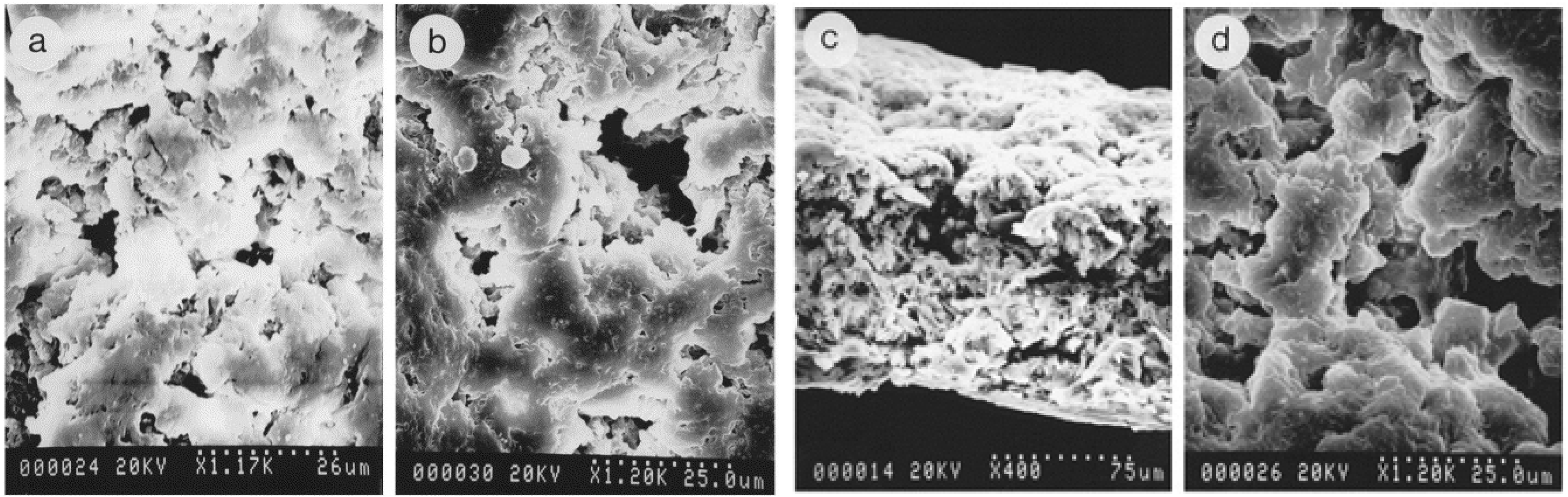
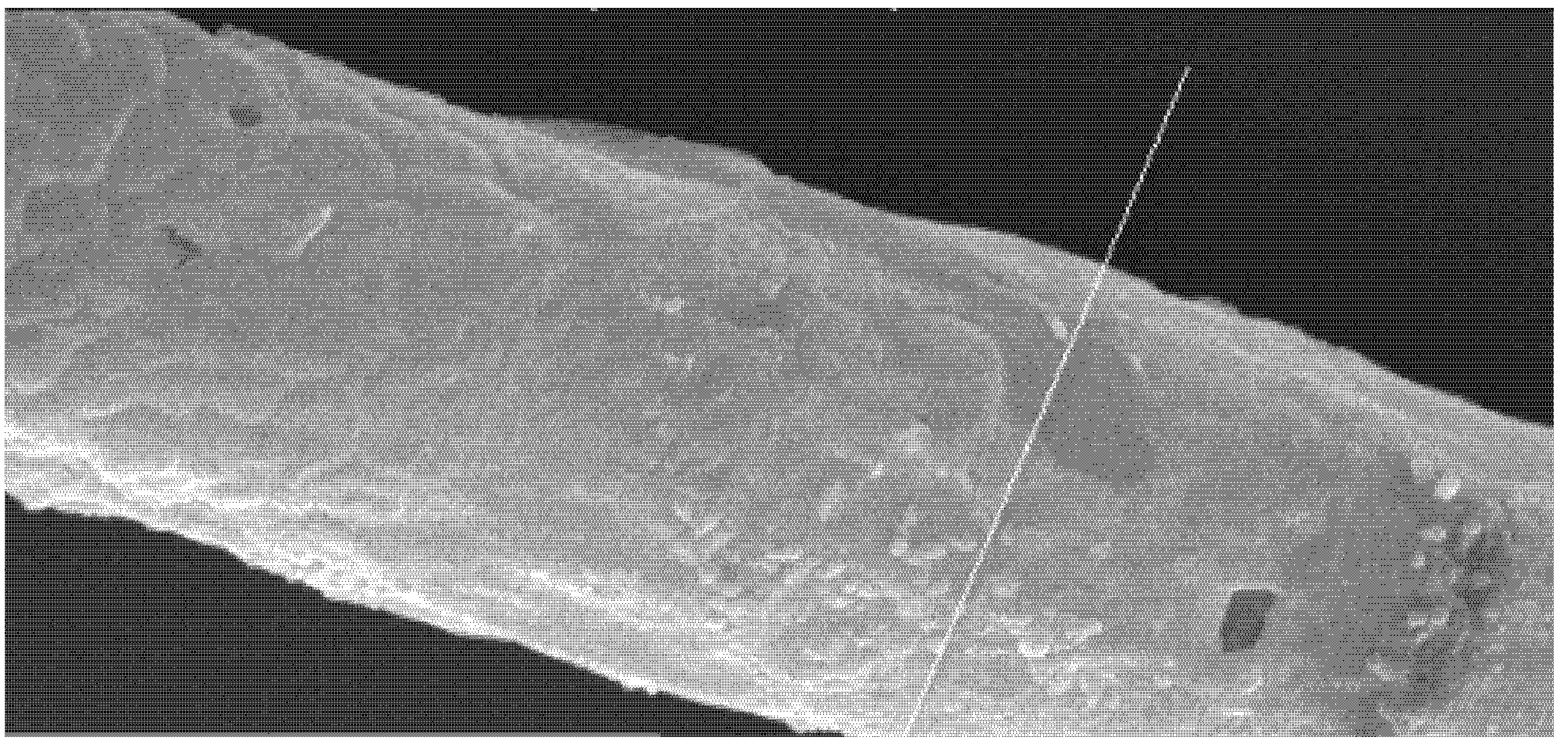
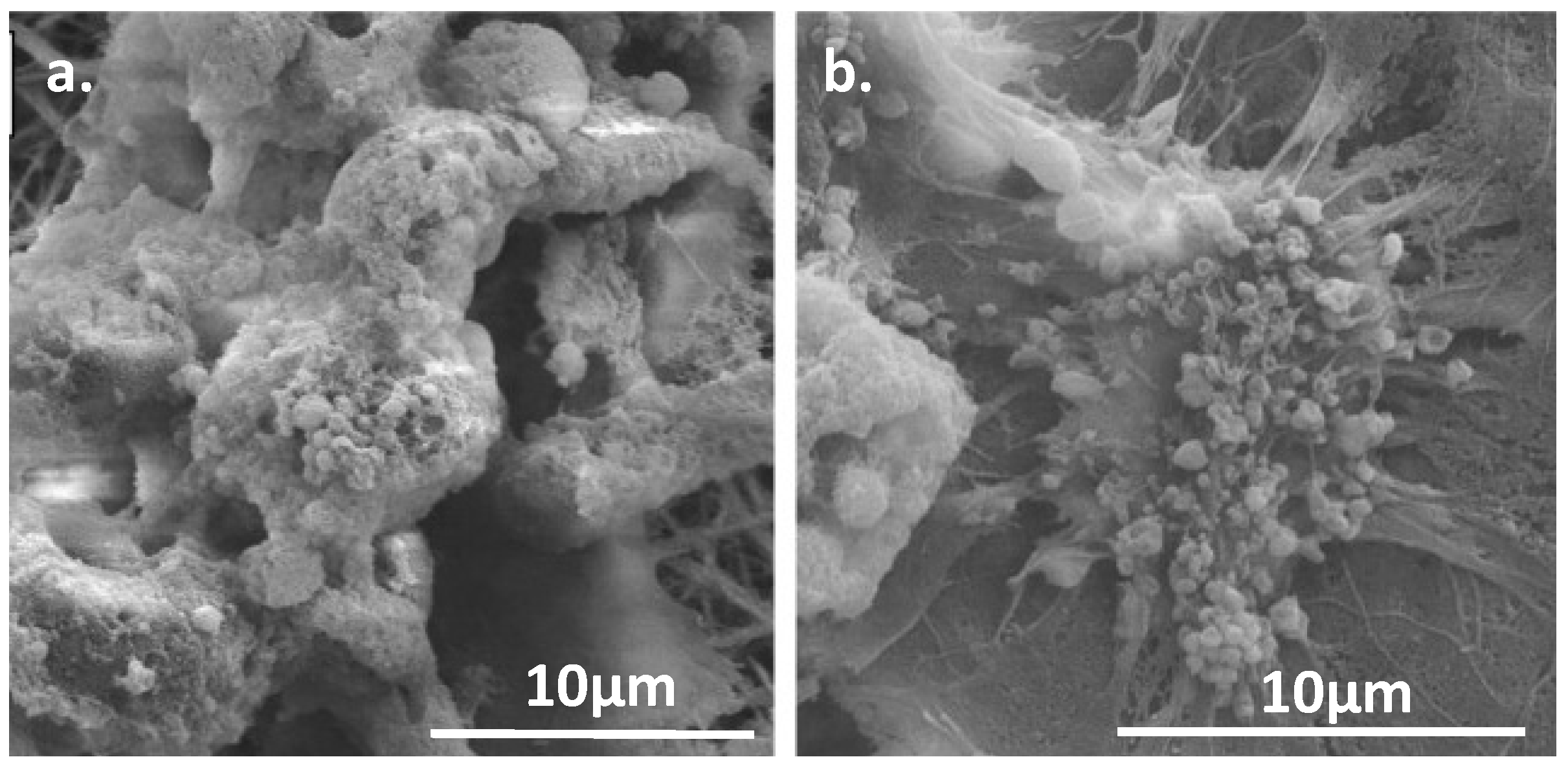
For tissue engineering purposes, it is desirable that fibers with similar mechanical and chemical properties be easily produced and processed to fit the intended function (
Figure 8). Such fibers are often made by electrospinning techniques which can yield fibers with diameters less than 100 nm [
30].
Figure 8.
High-magnification SEM photograph of hydroxyapatite fibers. Reproduced from [
31] with permission from John Wiley and Sons.
Figure 8.
High-magnification SEM photograph of hydroxyapatite fibers. Reproduced from [
31] with permission from John Wiley and Sons.
Similar fibers can also be achieved by sol-gel electrospinning, but with the added disadvantages that the material requires additives to get the necessary viscosity for spinning and a high temperature calcination step is required to remove them. Rather than wait for an apatite layer to form, these concerns can be eliminated by instead using newly developed electrospinning methods which produce hydroxyapatite fibers from the start. These engineered hydroxyapatite fibers can also benefit from the addition of helpful nanoparticles that can stiffen the matrix and contribute to the chemical properties of the structure without detracting from the mechanical strength. As such, the possibilities for material improvement are extensive and could be used to address a variety of situations.
2.3. Bioactive Glass Nanoparticles
Another fascinating material worth exploring is the useful ceramic, Bioglass. This is the commercial name for one of several glass-ceramic materials which are often used in tissue engineering due to their favorable mechanical properties and high bioactivity. When these glasses come into contact with physiological fluids (or simulated body fluids, SBF) their surface reacts to form an apatite layer which allows the material to form strong bonds to bone [
30]. This means that their applications can range from tissue scaffolds to surface coatings to filler material in composites. Initially, research into their properties was done with micrometer-scale particles, but Boccaccini
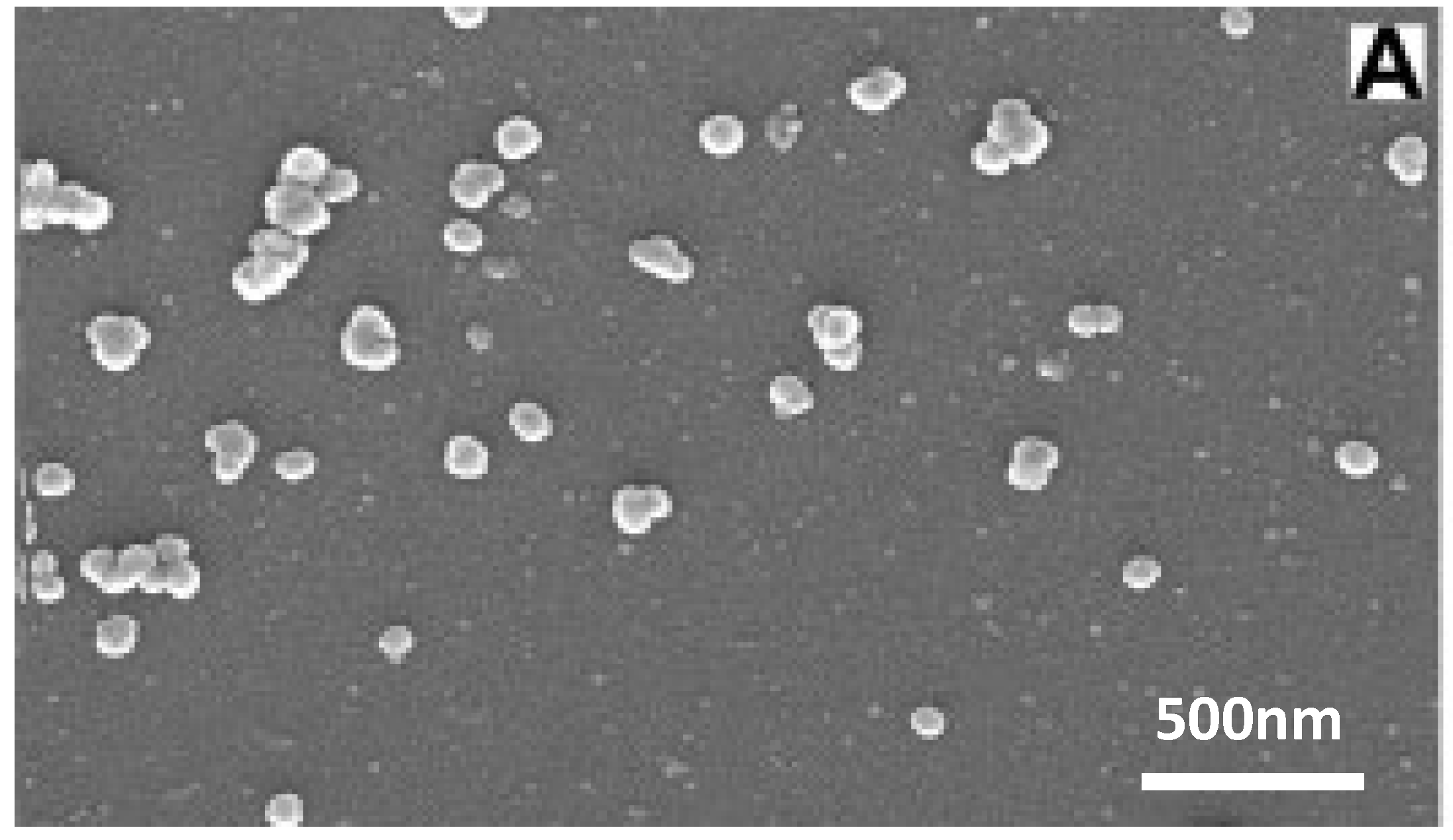
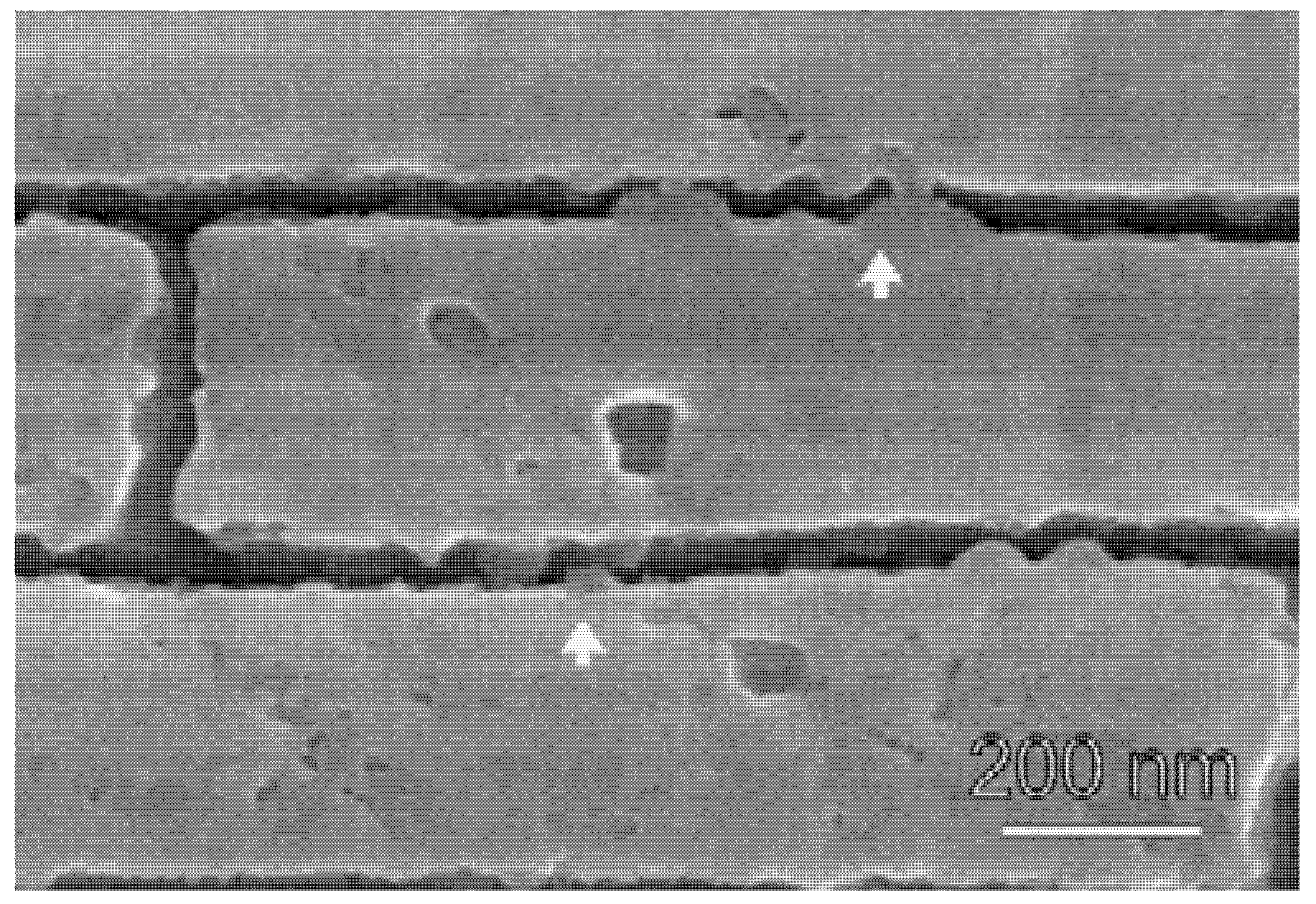
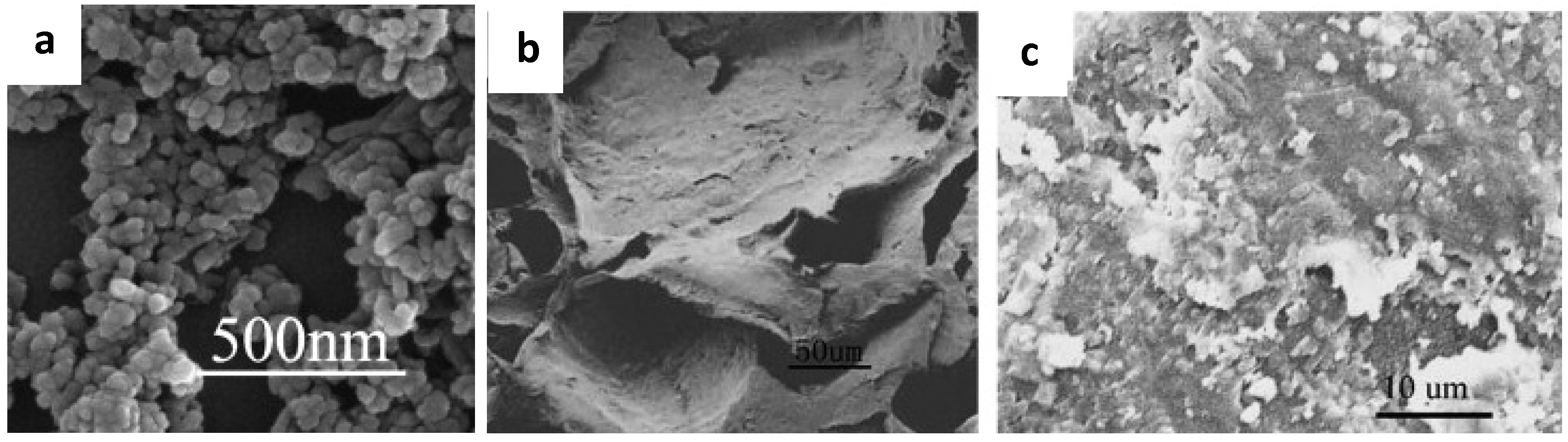
et al. found substantial improvements in biological function by transitioning to nanoparticles instead (
Figure 9) [
30]. The switch to the nanoscale means that the particles have a higher surface area to volume ratio which leads to faster release of ions, deposition, and tissue mineralization as well as higher protein adsorption [
30]. Nanoparticles also result in a better imitation of bone which naturally has nanosized hydroxyapatite particles, and therefore cells and proteins can adhere to nano-features. Boccaccini also points out that the reduced size helps them to stiffen polymeric nanofibers without causing structural disruption, to be processed into thin bioactive coatings, or used as an injectable system [
30].
Figure 9.
SEM of spherical bioactive glass nanoparticles with the formulation SiO:P
2O
5:CaO = 55:40:5 (mol). This demonstrates the homogeneity of the nanoparticles and also the aggregation characteristics. Reproduced from [
32] with permission from Elsevier.
Figure 9.
SEM of spherical bioactive glass nanoparticles with the formulation SiO:P
2O
5:CaO = 55:40:5 (mol). This demonstrates the homogeneity of the nanoparticles and also the aggregation characteristics. Reproduced from [
32] with permission from Elsevier.
Some additional improvements to these particles can come from surface coatings or other processing techniques that prevent agglomeration and help integrate the Bioglass into polymer matrices to produce superior composite materials. However, Liu
et al. found that the composites containing surface-modified nanoparticles had greater tensile strength than unmodified nanoparticles [
33]. The surface-modified composites also exhibited higher nucleation and crystallization rates because the nanoparticles acted as nucleating agents and the surface-modified particles were more uniformly dispersed in the scaffold. Finally, by using a mask during plasma activation, it is possible to selectively functionalize only part of the polymer surface so that apatite growth can be triggered only in predetermined areas [
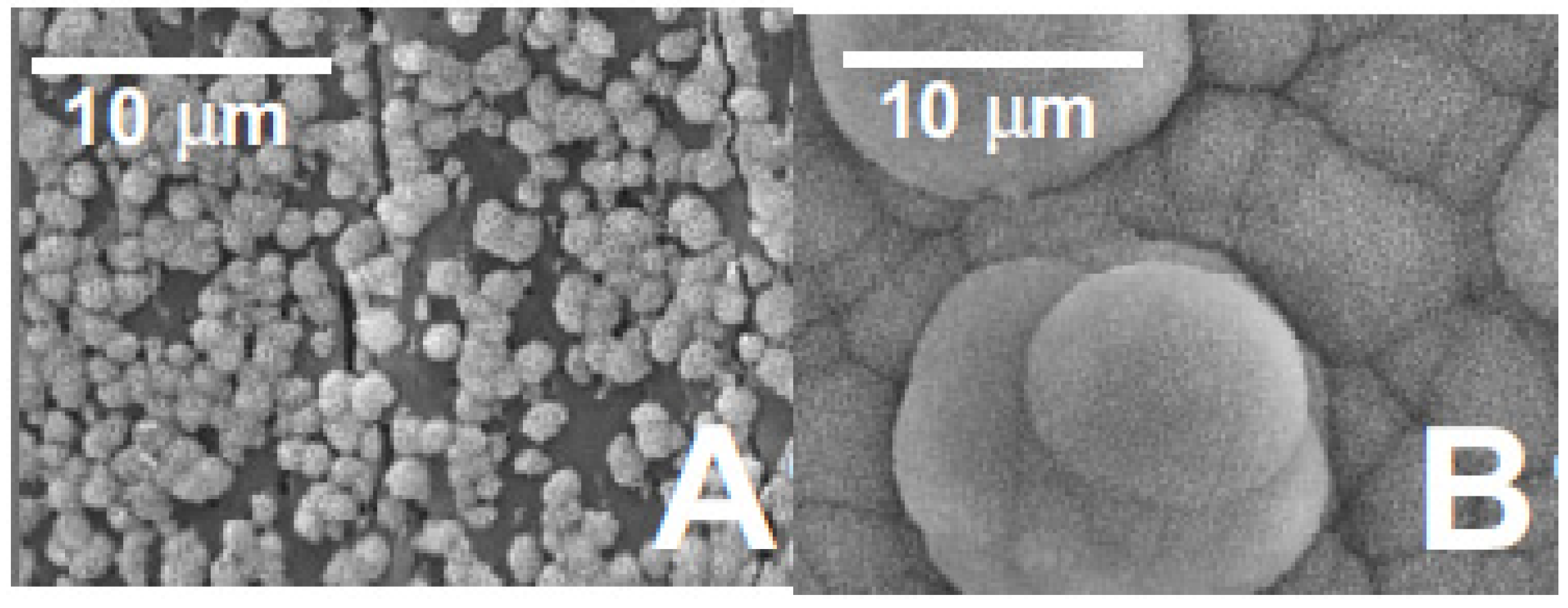
34]. Shi
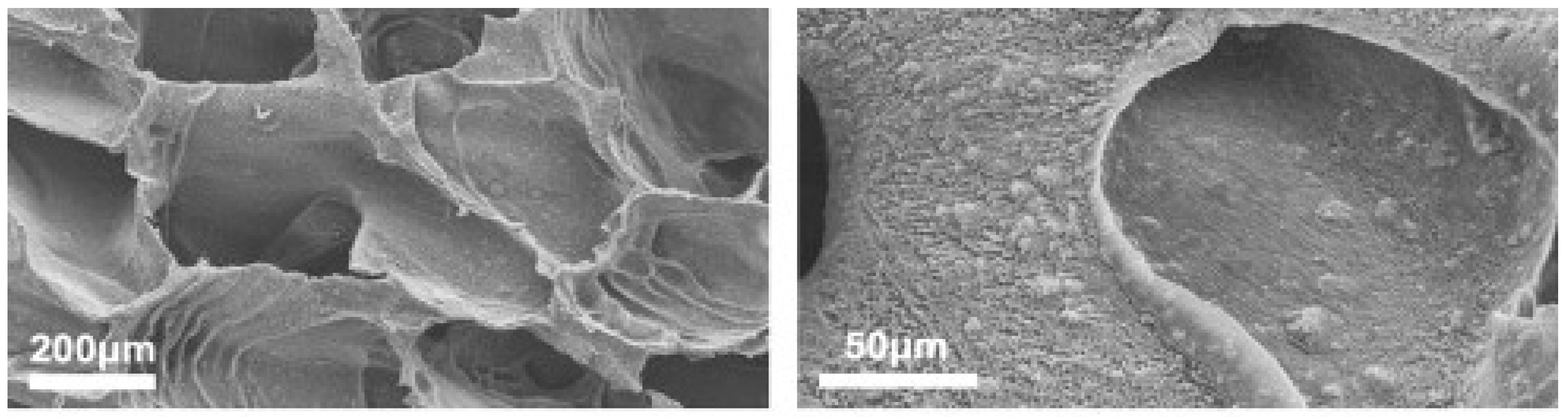
et al. concludes that this patterning ability especially could be used for the differentiation and control of cell growth on implant surfaces (
Figure 10) [
34].
Figure 10.
SEM images of different substrates after immersion in SBF for two weeks at (
A) 25 °C and (
B) 37 °C. Set 1 corresponds to PNIPAA-grafted PLLA films with 20% bioactive glass particles. The thermoresponsiveness of the particles is demonstrated by the selective growth of apatite after increasing the temperature. Reproduced from [
34] with permission from John Wiley and Sons.
Bioglass and other ceramic glasses are not the only nanoparticles that have contributed to the improvement of materials in the body. Lee
et al. have found computationally that nanoparticles dispersed in a polymer film can actually preferentially deposit themselves at sites where they are needed [
35]. They are driven there by the polymer chains in the system which will gain conformational entropy by stretching to accommodate particles within the film [
35]. This causes aggregation of the nanoparticles and pushes them into cracks in the surrounding matrix [
35]. Once they are in place, and if there is a continuous path bridging the crack surface, the nanoparticles are capable of transferring loads away from the cracked matrix to themselves [
35]. These trapped particles then bind to the matrix and, if they are bioactive, begin to heal it. Due to their small size, these particles can easily be incorporated into a variety of scaffolds, injected, or administered to the site of interest by other means. However, bioactive glass-ceramics are not the only innovation in nanoparticles for the life sciences, there are also a variety of polymeric nanoparticles.
2.4. Drug Delivery
Nanomaterials have made a monumental impact on the field of drug delivery. Unlike larger particles, nanoparticles have the ability to reach far more sites in the body, can circulate for longer periods of time, have higher effective surface areas, can control drug release, and can even cross the blood-brain barrier. The incorporation of drugs into nanoparticles allows them to be delivered directly to the site where they are needed, which is more efficient and reduces the required dosage. Nanoparticles are also capable of passing through Peyer’s patches which regulate the environment of the small intestine and therefore can be administered intravenously [
36]. However, nanoparticles also face challenges such as undesirable recognition as a foreign body and consequent filtration by the liver or spleen before the drug can be delivered. To avoid this, there are several broad solutions which must be optimized for each drug-nanoparticle combination to obtain the intended size, release rate, and circulation time.
Before the nanoparticles can deliver a drug to its target, the drug must first be incorporated into the particle. While the drug could theoretically be attached to the nanoparticle after formation via adsorption, larger amounts can be incorporated by introducing the drug during the nanoparticle formation process [
37]. Common methods for this step which will be presented briefly include: solvent evaporation, spontaneous emulsification, salting out, supercritical fluids, coacervation, and polymerization. Solvent evaporation refers to a process in which the desired drug and polymer are dissolved in an organic solvent, emulsified with an aqueous solution, and then solvent is evaporated from the emulsion [
38]. However, this process is energetically expensive and does a poor job of encapsulating hydrophilic drugs [
39]. Spontaneous emulsification is the same as solvent evaporation except a water-soluble solvent is also added to increase diffusion in the emulsion and therefore reduce the resulting particle size [
37]. The spontaneous method is also faster and results in a more porous product than that achieved by evaporation [
21]. Salting out was developed in order to avoid using chlorinated solvents which leave behind harmful residuals that can be difficult to remove and degrade components that they come in contact with. In this process, the addition of a salting-out agent allows a liquid-liquid phase system of normally miscible compounds to form. This forms an oil-in-water emulsion to which excessive amounts of water are added to yield the nanoparticles [
22]. The supercritical fluid method also aims to get around using harmful solvents in the production of nanoparticles. It can be done in two ways. The first is involves the rapid expansion of a supercritical solution such that the dissolved solute precipitates out when the solution is expanded and loses its improved dissolving power [
37]. However, because very high molecular weight polymers are preferred for many drug delivery applications and they have low solubility even in supercritical fluids, production has shifted to a supercritical anti-solvent method [
37]. In this method, the solute is dissolved in an organic solvent and precipitates as the pressure is increased to the point that all residual will be removed [
37]. Coacervation also uses phase separation to create nanoparticles. Polymerization methods depend on the polymer chosen for the application; however, generally the drug is dissolved in an acidic polymerization medium before the addition of the monomer and then the polymer forms by anionic mechanism with mechanical agitation [
31]. To improve the quality of the product and prevent nanoparticle aggregation, surfactants and stabilizers can be added.
Next the nanoparticles need to be optimized for their intended function. Important things to consider include the final size of the particle, aggregation phenomena, and surface characterization. Encapsulation efficiency is known to correlate with the diameter of the nanoparticles so rapid dissolution can be achieved with particles on the order of 100 nm and more sustained dissolution with particles of approximately 800 nm [
39]. At the same time, the target site of the nanoparticles is an important consideration. For example, nanoparticles whose surfaces had been modified with chitosan were found to have increased penetration to mucosal surfaces [
39]. Nanoparticles in the body also have to contend with plasma protein adsorption, phagocytosis, and the MPS [
40]. Phagocytes will attach to the nanoparticle surface when opsonins in the blood adsorb onto the hydrophobic portions of the nanoparticle, but this can be prevented by grafting hydrophilic particles such as polyethylene glycol onto the surface [
40]. While the activity of phagocytes may be helpful if the intended target is in fact the liver, this uptake could be dangerous if there are cytotoxic components in the nanoparticles [
40]. Initially, researchers considered solving this problem by suppressing the reticuloendothelial system; however, this could lead to a new set of problems and therefore has not been an ongoing focus of research [
40]. Rather, hydrophilic nanoparticles are favored for drug delivery applications because they are filtered out at a much lower rate than their hydrophobic counterparts. To take advantage of this fact, nanoparticles can either be polymerized from hydrophilic polymers to begin with or treated after production to become so [
37]. Hydrophilic polymers frequently used in polymerization include chitosan and gelatin, which can both form nanoparticles through an ionic gelation method [
37].

