Article

Novel Solution for Low-Lying Land Areas Safe from Natural Hazards—Toward Reconstruction of Lost Coastal Areas in Northeast Japan

by
Toshio Nakajima
and
Motohiko Umeyama
*,†
Department of Civil & Environmental Engineering, Tokyo Metropolitan University, 1-1 Minamiohsawa, Hachioji, Tokyo 192-0397, Japan
*
Author to whom correspondence should be addressed.
These two authors contributed equally to this work.
J. Mar. Sci. Eng. 2015, 3(3), 520-538; https://doi.org/10.3390/jmse3030520
Submission received: 13 May 2015 / Accepted: 26 June 2015 / Published: 10 July 2015

Abstract

:
The imminent fear of water-related hazards such as flooding hangs over low-lying areas, in particular now because climate changes have led to increased hazards, like storm surges, that could result in serious harm. This paper aims to provide a novel solution—namely “the floating platform”—that can transform dangerous low-lying areas into those safeguarded against potential hazards. Additionally, by utilizing this solution as a secure base for society to build atop this new artificial reservoir, we offer a better future role for such areas. Meanwhile, we propose adoption of our concept soon at two low-lying areas in northeast Japan hard-hit by the huge 11 March 2011 tsunami: Sendai’s Arahama coastal district and the still-devastated residential harbor area of Kesennuma, both cities in need of a fresh perspective.

1. Introduction

In recent years, although there have been many other natural hazards like earthquakes and tsunami, the 26 December 2004 earthquake in Sumatra estimated at a magnitude of 9.3 resulted in 283,000 lives being lost in the wake of the subsequent gigantic tsunami. In addition, in Japan, there was the Tohoku Earthquake on 11 March 2011, which caused great damage. The 9.0 magnitude earthquake took place about 130 km off the northeast Japanese coast in the Pacific Ocean some 5800 m in depth, but it is thought that a total of more than 19,000 lives were lost, with the concomitant tsunami entering 5 km inland from the shoreline. The earthquake had generated a record tsunami under modern Japanese meteorological observations, with a maximum height of 9.3 m and at some locations peaking at 40.1 m.
Meanwhile, the Intergovernmental Panel on Climate Change (IPCC 2014) report estimates that the average global temperature will rise 2.6 to 4.8 deg. by the year 2100, relative to 1990, and the sea level will rise ranging from 45 to 82 cm [1]. The acceleration in the global warming trend is due to the effects of greenhouse gases, such as carbon dioxide [2]. This in turn has brought attention to problems such as the rise in ocean temperature as well as in the sea level. Moreover, the amount of sea level rise is not uniform around the globe’s surface as Earth’s spin has a greater effect on the islands and nations situated near the equator. Tuvalu, located in the South Pacific, is one example where videos show seawater rushing far inland at high tide, portending the destruction of this nation. The other examples are Nauru and the Cook Islands, coincidentally in the South Pacific, devastated by a huge cyclone whose effects were multiplied by the sea level rise there [3]. In 8 November 2013, typhoon Haiyan destroyed about 70% to 80% of structures in its path as it tore through Leyte Province in the Philippines. Huge storm surges up to 5 m high surging inland swept away coastal villages.
Important urban centers are located along low-lying coastlines and are subsequently increasingly at risk of flooding due to for instance heavy rain and storm surges. These areas face the most serious situations when flooding due to heavy rain, and storm surges due to typhoons, tsunamis and so forth occur. Moreover, the relative ground level of these areas will become much lower level than the mean surface of the sea because of the sea level will rise due to global warming in the future. In addition, these risks can be reduced if we introduce the very large floating structures (VLFS) which can be employed as secure bases for urban settlements to reduce these risks [4,5]. From the standpoint of a shift in thinking, these areas may be transformed in terms of conditions; we do not need to worry about the sea level rise here if these areas are filled with water up to the level of sea surface. Then for the utilization of open space on water, floating platforms can be used for various human activities thereon. As a secure base for the urban areas, we recommend a VLFS such as the “Mega-float” be used since they have more stability, just like large tankers are much more stable than small fishing boats. We do believe that the combining construction of the artificial reservoir and utilization of the VLFS, will produce a novel solution especially for the low-lying land areas. This paper explains how this novel solution in the low-lying land areas is first of all safe, then presents two applications of our concept to some engineering studies.

2. A Floater-Based Novel Solution against Natural Hazards

2.1. About the Floating Sea Berth “Marine Gate Shiogama”

Humankind, while basking in its own glory because it had gained progress in use of science and technology, appears to have lost both respect for and fear of nature. It may be true that many hitherto impossible things have been realized due to advances in science and technology, but in the past it has not been necessarily the case that humankind has taken on nature directly. For example, the dikes of yore which were still technologically unsophisticated for the most part emphasized water flow redirection, thus enabling more people to escape when faced with disastrous situations. Yet, in recent times, high-strength concrete has been used as a construction method for building tall and strong dikes and/or seawalls that just through sheer force seek to wrest with water, resulting in the skyrocketing of construction costs as well. The authors thus decided that, in order to deal with water-related hazards as exemplified by floods, the answer lies not in dealing head-on with these problems using massive structures like dams and/or dikes and seawalls but taking the indirect approach of simply living with the water, to keep to a minimum the effect of water-related hazards in a more economical manner.
After the Great East Japan Earthquake on 11 March 2011, we found the video of the floating sea berth which had been hit by the huge tsunami that depicted (available via YouTube [6]) in northern Sendai, “Marine Gate Shiogama”, where the water depth was 4.5 m. This visual record proves that floating platforms moored properly are extremely stable and safe against tsunami. The 3.4 m tsunami approached this floating sea berth of 220 m in total length. Consisting of four rectangular pontoons (each pontoon sized 51.5 m in length by 9 m in width by 4 m having rollers on four corners touching four 7.5 m-high poles), the hybrid PC pontoons move safely and freely in place along the poles. The footages show the floating sea berth moving up slowly by about 3.4 m vertically in about 90 s. The tsunami had not risen quickly (estimated about 0.04 m/s from footage). In contrast, the tsunami was extremely destructive only against fixed structures since the fixed structure in total bears the entire load of the tsunami onto it directly. We realized that this video offers excellent information about how to deal with serious natural hazards. We are convinced that the floating platform is very safe and useful. We also realized not only are the floating platforms safer with their inherent ability to “ride out” rapid water level rises, they are economically more sensible when viewed from the standpoint of resilience vis-à-vis natural hazards; when compared to land-based building structures that would require rebuilding from scratch in face of extensive damages, they are less likely to be damaged while being easier to replace.

2.2. Construction Scheme Solution

The upper portion of Figure 1 shows the typical case of free floating platform with the support piles in a water area. When there is an unexpected increase in water level due to floodwater resulting from heavy rains, storm surges due to hurricanes and/or typhoons, tsunamis and so on, the floating platform can easily lift itself up from the original position. Under special circumstances, such as in the case of extremely high tides, tall support piles may be needed to maintain the position of floating platforms in face of a huge tsunami, storm surge and so on. To avoid the vertical and horizontal motions of floating platform, the support piles may be used underneath the floating platform as the so-called “Soft-landing System” shown in the lower portion of Figure 1 [7,8,9]. In this case, the floating platform is supported partially in displacement by these support piles underneath the floating platform. Since a floating platform stays afloat independently, it can be freely and easily moved in the horizontal direction within the man-made lagoon and, when connecting the floating platform and its supporting piles, vertical adjustment can be precisely controlled through changes in the weight of the ballast water inside the floating platform. In the case of Figure 1B, additional mooring facilities could be required to prevent horizontal excursion of the floating platform when the floating platform moves up in accordance with water rise conditions.
Our novel solution for the low-lying land area is based upon the combined system of constructing the artificial reservoir in low-lying land area and the large-scaled floating platforms to utilize the open water surface for living activities. It targets how such a dangerous lower-lying land area can be turned in a safe area against flooding due to heavy rain, tsunami and so on. Basically, the floating platforms in such enclosed artificial water area are extremely safe since the surrounding land area protects the various invading hazardous water as the barrier of the floating platforms. In addition, since the large water surface area of the artificial reservoir is covered by floating platforms, the hydrodynamic energy due to the induced inner waves and currents is somewhat dampened generally. Furthermore, in the case of the Soft-landing System, the oscillatory motions of the floating platforms due to the external hydrodynamic pressure can be designed to be reduced by adjusting their natural frequencies of vertical platform motions through selection of elastic restoring coefficient of the rubber fender on the supporting piles.
An example of a low-lying waterfront zone at sea level near an ocean and/or river is presented below. The plan is to alter the potential danger posed by this location, then produce an area safeguarded against the abovementioned natural hazards. An outline of the construction process of the floating platform system on this low-lying land area follows.
Figure 1. Floating platform with support piles.
Jmse 03 00520 g001
As a first step, an area approximately half of the size of this location is to be excavated to a depth of several meters (say 5 m) and the topsoil is to be removed from the location. The topsoil is to be carried to the boundary of the planned area in order to raise the low-lying land area above sea level (see Figure 2). These are filled with freshwater and/or saltwater until the water level behind the levee reaches sea level, to bring forth a man-made lagoon (see Figure 3). Finally, buildings are to be constructed on the floating platforms inside the man-made lagoon. Road bridges with flexible joints are to be built to enable travel between the floating platforms and the land. In general, the larger the area of water surface is provided, the more comfortable the amenities are. However, the open water surface does not need to be larger than the surface area of the floating platform at first. Figure 4 shows the plan view of the construction process of water area with floating platforms and also explains how to develop the area of water area inside the low-lying land area. In the beginning, the building on land is to be changed to the floating platform system independently. Then gradually the water areas are to be connected each other for the use of water-borne transportation to river and/or sea next. In the final stage, larger floating platform may be constructed as the floating foundation for building plural housings.
Figure 2. Original land condition and the land condition after removing soil.
Jmse 03 00520 g002
Figure 3. Final view of the floating platform in the man-made reservoir.
Jmse 03 00520 g003
Figure 4. Developmental stages of the water areas with floating platforms.
Jmse 03 00520 g004

3. Case Study 1: Recovery Scheme for Arahama Coastal Zone Destroyed by Huge Tsunami

3.1. About the Site at Arahama Area

Arahama was a popular swimming spot surrounded by beautiful rural surroundings that would fill up every summer. It is sad and painful to realize that from one moment to the next this place as well as the hundreds of people residing there were gone. To protect the agricultural fields from salt injury, the shore of Sendai had a forest of black pine trees that was planted there over 200 years ago in the Edo era. In addition, this area had the longest canal of Japan, namely the 46.4 km Teizan Canal that was developed along the long shore by the famous samurai Date Masamune. The Arahama area is located along the coast of Miyagi Prefecture and faces the Pacific Ocean (see Figure 5). The rural residential area is filled with low-rise housing that is surrounded by rice-fields. This area had a population of about 2700 people and 800 households. On 11 March 2011, Japan was struck by a major earthquake-tsunami disaster. One of the most affected sites was the Arahama area. A tsunami wave of 9.38 m hit this area and inundated about 13 km2 and hundreds of people lost their lives. Most houses along the shore were lost.
Figure 5. Project sites of Arahama and Kesennuma.
Jmse 03 00520 g005

3.2. Reconstruction Scheme for Arahama Coastal Area

We propose to apply our solution to the destroyed coastal area of northeast Japan and we would call this scheme the “Coastal Aqua-Villages” scheme [10]. The plan is to change the threat of water-related hazards so that these areas can become safe residential areas particularly in light of storm surges due to huge typhoons and massive tsunamis. The left portion of Figure 6 shows the current dangerous housing situation along the shore. The 2011 earthquake left these areas more vulnerable as the ground level dropped with 40–80 cm. Because it is almost impossible to add soils to return to the original ground level, the objective of this scheme is to introduce a waterfront development for villages along the Arahama shore: Social infrastructure will be built on floating platforms that will not submerge in case of rising water levels and will thus provide a safe and comfortable living environment.
Figure 6. Original coastal area and the coastal area after removing soil.
Jmse 03 00520 g006
To realize this, the currently hazardous areas will be excavated to a depth of 3–5 m and the topsoil will be removed. The topsoil removed from the site will then be relocated in order to construct banks that will protect the residential areas against a run-up of seawater due to storm surge and/or high waves (see the right portion of Figure 6). Next, the excavated areas will be filled with water including saltwater until the water level reaches sea level to construct a man-made lagoon. Finally, the floating platforms made by lower cost materials such as light-weight concrete are constructed to host homes and even rice paddies (see Figure 7). The plan view of the man-made lagoon of reconstructed Arahama area is shown in Figure 8. The man-made lagoon is constructed about 200 to 250 m from the shore and is connected to sea by a 30 m wide canal used for transportation. A 5 m high water gate is then constructed inside of the canal to protect the man-made lagoon from high tide. The Teizan Canal is also connected to the man-made lagoon. The man-made lagoon is surrounded by higher banks with black pine trees (height of bank will be 15 to 20 m coastal side and 10 m inland side) constructed by excavated soils from the man-made lagoon. To be precise, the lost residential area of 800 m by 600 m is excavated and the residual soil of 1,800,000 m3 is used to construct higher banks which surround the artificial water area. The total area of the floating platforms inside man-made lagoon will be 230,000 m2 for 300 to 400 low-rise housings and agricultural fields (see Figure 9).
Figure 7. Final view of the floating platform in the man-made lagoon.
Jmse 03 00520 g007
Figure 8. Plan view of the reconstruction for Arahama coastal area.
Jmse 03 00520 g008
Figure 9. Satellite view of reconstructed Arahama coastal area (Image as represented by architectural model).
Jmse 03 00520 g009

3.3. System of Floating Road for “Arahama Coastal Aqua-Villages”

The floating platform system consists of two elements: one is the box-type structural frames used for public roads called “Floating Roads” and the other is the floaters where low-rise housings and/or agricultural fields are built on (see Figure 10). Floating roads with steel guiderails are connected to the tall vertical support piles. These tall vertical support piles with guiderails 20 m high are constructed for the unexpected extraordinary vertical excursion of floating platforms due to huge tsunami and so on. For access to the outside four public roads are connected with the floating roads, constructed for other purposes as structures in addition to use as a structural enforcement frame for floaters inside the man-made lagoon. These floating roads are not only used for automobiles and/or pedestrian access but also to provide for inner space of the floating roads for many kinds of infrastructure such as water supply, sewage water, electricity, communication lines and so on. The material of these floating roads comprises lightweight concrete and/or steel which can be recycled many times. Multiple standard module units of the floating roads are constructed at distant construction yards and are towed to the site by ship. Then these modular units of the floating road are connected with each other to extend the size of floaters where residences, warehouses and even rice fields are located on them (see Figure 11). Floaters used for various purposes are supported by fixtures which attach to the lower structure of the floating roads. The material and the structure of floaters vary depending on the size and purpose of upper buildings, kinds of use and so on. Extremely simple and low cost materials are used for rice fields while very rigid and strong steel structures are used to realize larger sized buildings having many stories for living and so on. To prevent horizontal excursion of floaters, the tall vertical support piles are erected besides the floating roads where the rollers or wheels are attached to allow vertical excursion of the floating platform system. The construction of the floating platform system is carried out step by step. Some floating roads are constructed first inside the man-made lagoon followed by the floaters next before finally the tall vertical support piles are set. The detailed sectional view of the standard module unit of the floating road is shown in Figure 12. The upper portion of the inner space is used for piping, electrical circuitry, communication lines and so on while the lower portion is used for storage, ballast and the like. The height of the floating road is 4.5 m with the draft being 2.5 to 3.0 m and the width, 10 m. The length of the floating road varies from 60 to 120 m and can be extended more depending upon the size of floater. The floating roads are attached to tall vertical support piles which support the horizontal current loads of storm surge, tsunami and suchlike exerting effects on the floating roads. These floating roads can move up and down freely due to the tidal vertical movement along the tall vertical piles with the attached rollers and/or wheels fixed on the floating roads.
Figure 10. Schematic plan view of the floating roads with floater.
Jmse 03 00520 g010
Figure 11. Bird’s-eye view of the floating roads with floater (Image as represented by architectural model).
Jmse 03 00520 g011
Figure 12. Detailed sectional view of the floating road with support pile.
Jmse 03 00520 g012

4. Case Study 2: Recovery Project for Kesennuma Bay Area Damaged by Tsunami

4.1. Architectural and Engineering Concepts for Kesennuma

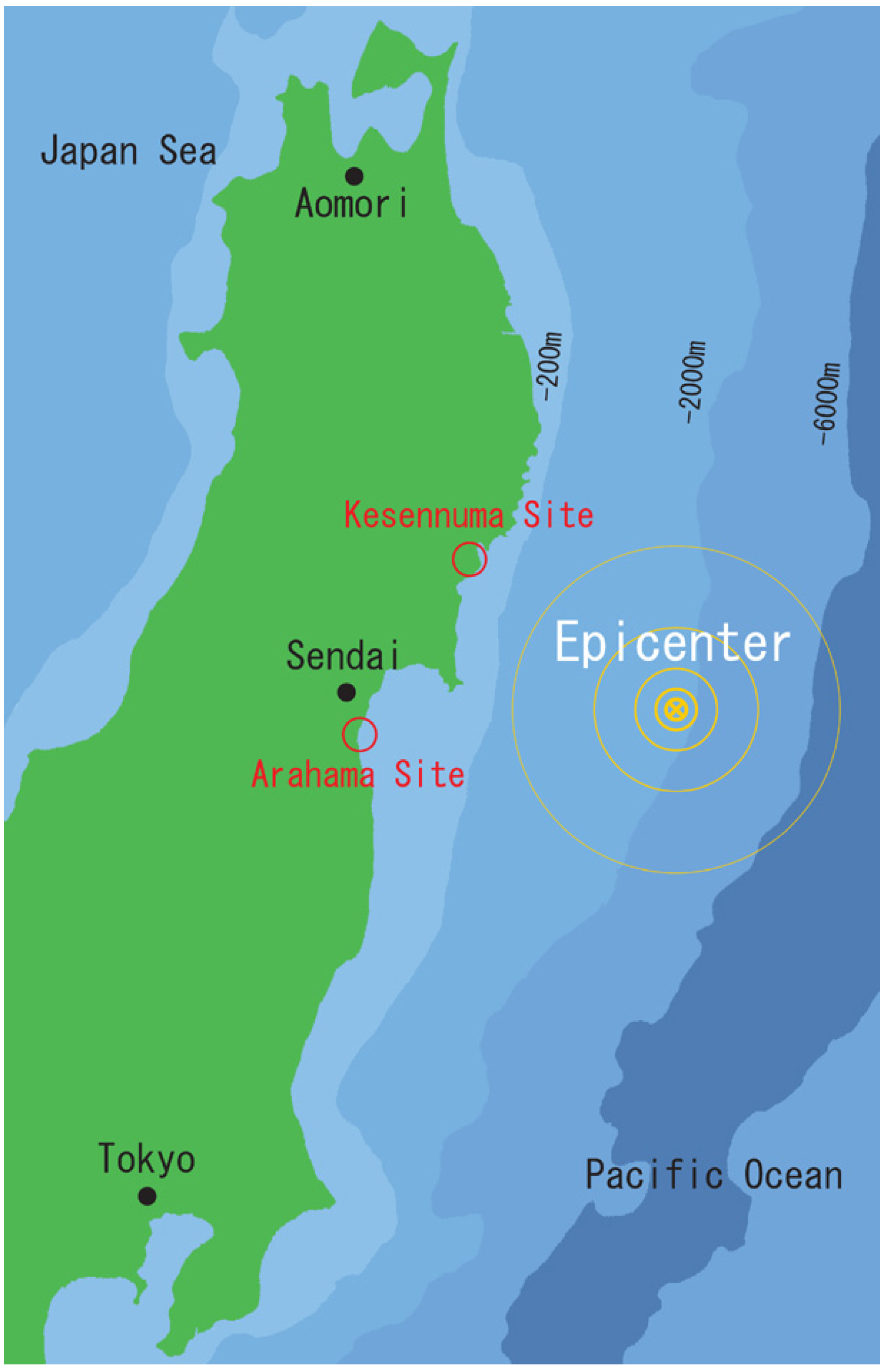
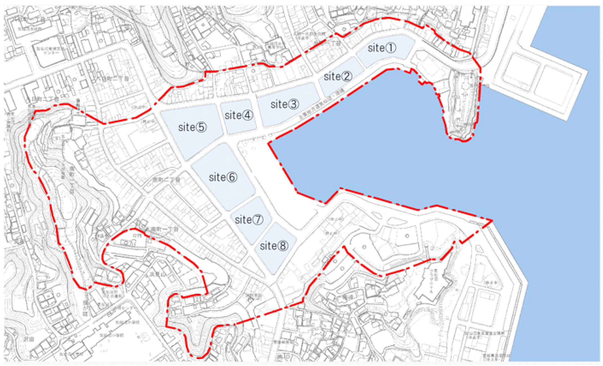
We would also propose the “floating platform” scheme to be included in the recovery plan for the destroyed Kesennuma Bay area shown in Figure 13. Here great numbers of residences and commercial buildings including fishery-related businesses and workplaces were located. The fundamental difference between the recovery of Arahama and Kesennuma Bay area is that the latter regards a much greater population. In addition, as Kesennumma Bay encompasses many fishery-based workplaces and tourist attractions its reconstruction will be more complicated. The scheme that we propose for the restoration of the Uo-machi/Minami-machi area of Kessennuma City is based on some architectural and engineering studies that are presented in this paper. While mitigation of adverse effects is important, the idea is to also maintain Kessennuma’s historical and cultural facilities and ensure that industries, namely fishery and tourism in which about 40% of Kessennuma’s inhabitants are involved, are restored. Furthermore, it is important to ensure a comfortable and intimate environment, provide space for different community schools, and restore important architectural landmarks damaged by disasters as memorial centerpieces.
Moreover, to ensure safety against major tsunamis, we simultaneously propose to raise the ground level up to 2.0 m for regional access roads like the so-called Kessennuma Bay Road to produce a first line of defense, in addition to the shoring up of the bay area comprising eight district blocks using the floating platform system—able to withstand strong earthquakes and huge tsunami—to be placed on the excavated artificial water areas.
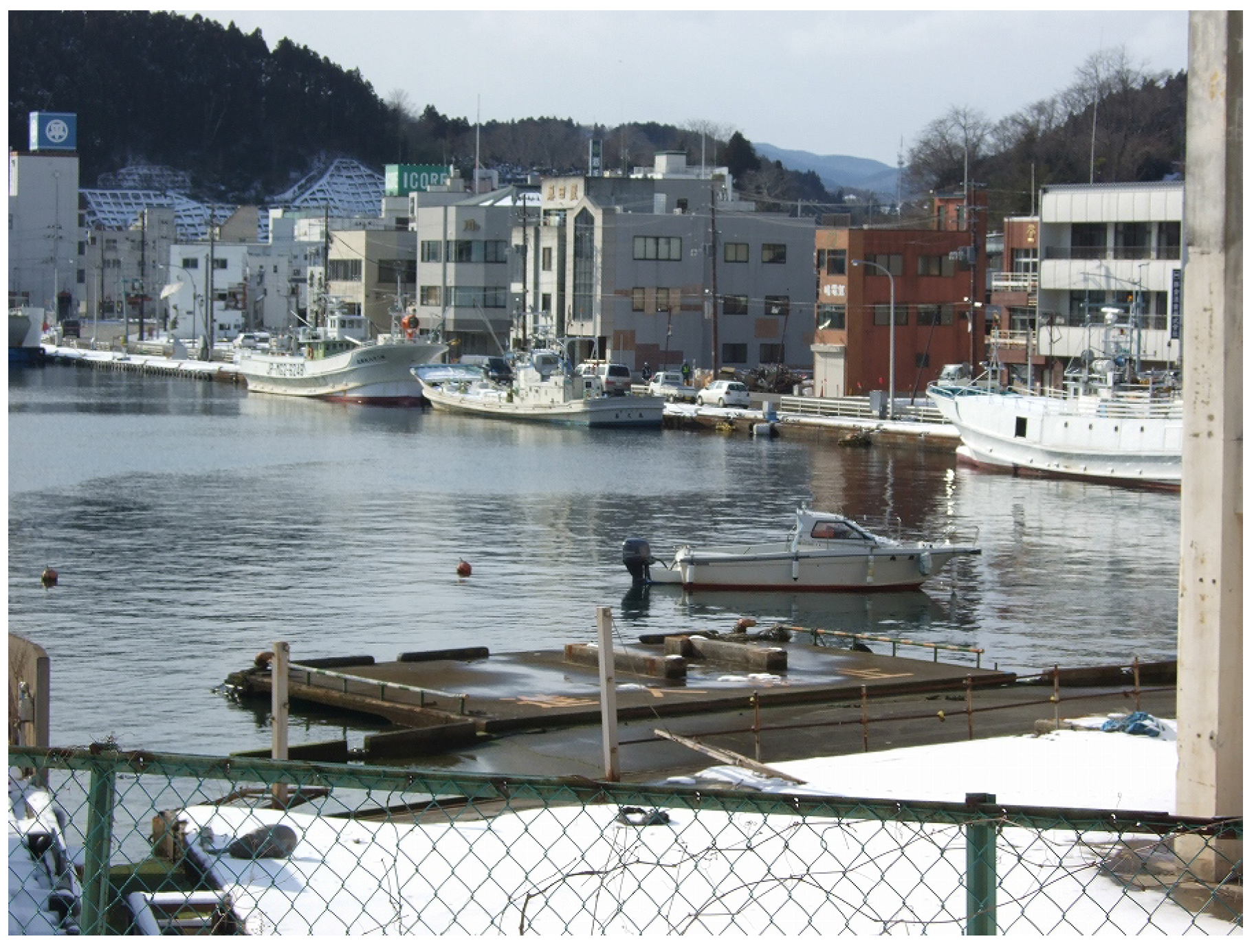
Figure 13. Damaged Kesennuma Bay area.
Jmse 03 00520 g013
Architectural functions, mainly public spaces such as the commercial/office facilities, restaurants/coffeeshops and so forth will be situated on the first and second floors while residential spaces will be situated beyond the third floor residential space to produce an integrated floating complex where work and habitation are integrated [11]. In the Fiscal Year prior to the great disaster, the region’s population was recorded as being 840 people (340 households). Looking at future development possibilities however, we propose a population of 1280 people (520 households, though for the floating complexes a total of 268 households was set) as the maximum population. Additionally, this development proposal proposes to have 124 of 274 fishery facilities to be located on the floating platforms together with some 20 community schools.
Meanwhile, according to a guideline produced by the Ministry of Land, Infrastructure, Transport and Tourism, comprehensive tsunami countermeasures that divided tsunamis into two categories—frequent tsunami and giant tsunami. A frequent tsunami occurs in a range of from once in several decades to once in about 150 years and meets the Level 1 height of 6.2 m. A giant tsunami occurs infrequently but causes massive damage. Flooding behind seawalls and/or dike of 6.2 m in this case is envisioned and evacuation is a vital part of countermeasures (disaster mitigation) in principle. Regarding Level 2 for dealing with the giant tsunami category, the proposal sees the use of the floating complexes found on the inner portion of the town to realize a mechanism which enables it to ride through a tsunami with a maximum of 12.0 m; as for those located on the periphery, evacuation routes were set in consideration of the fact that there would be enough time to evacuate.
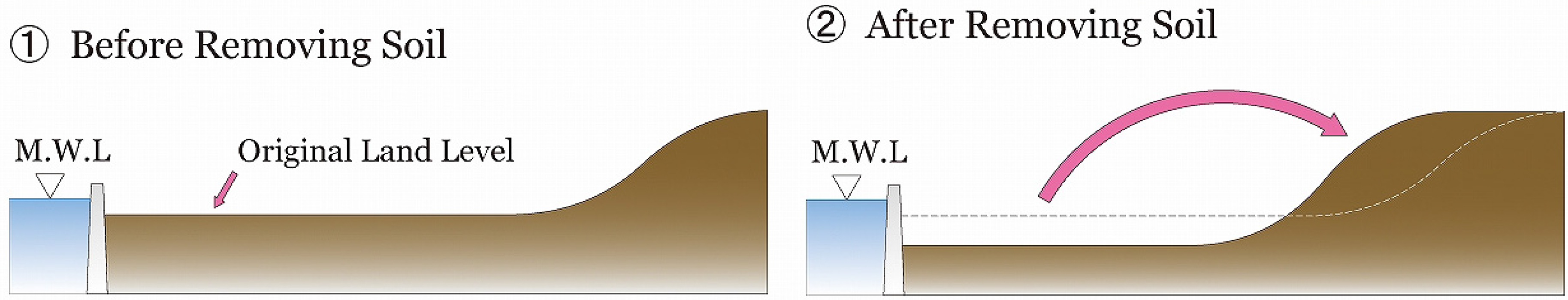
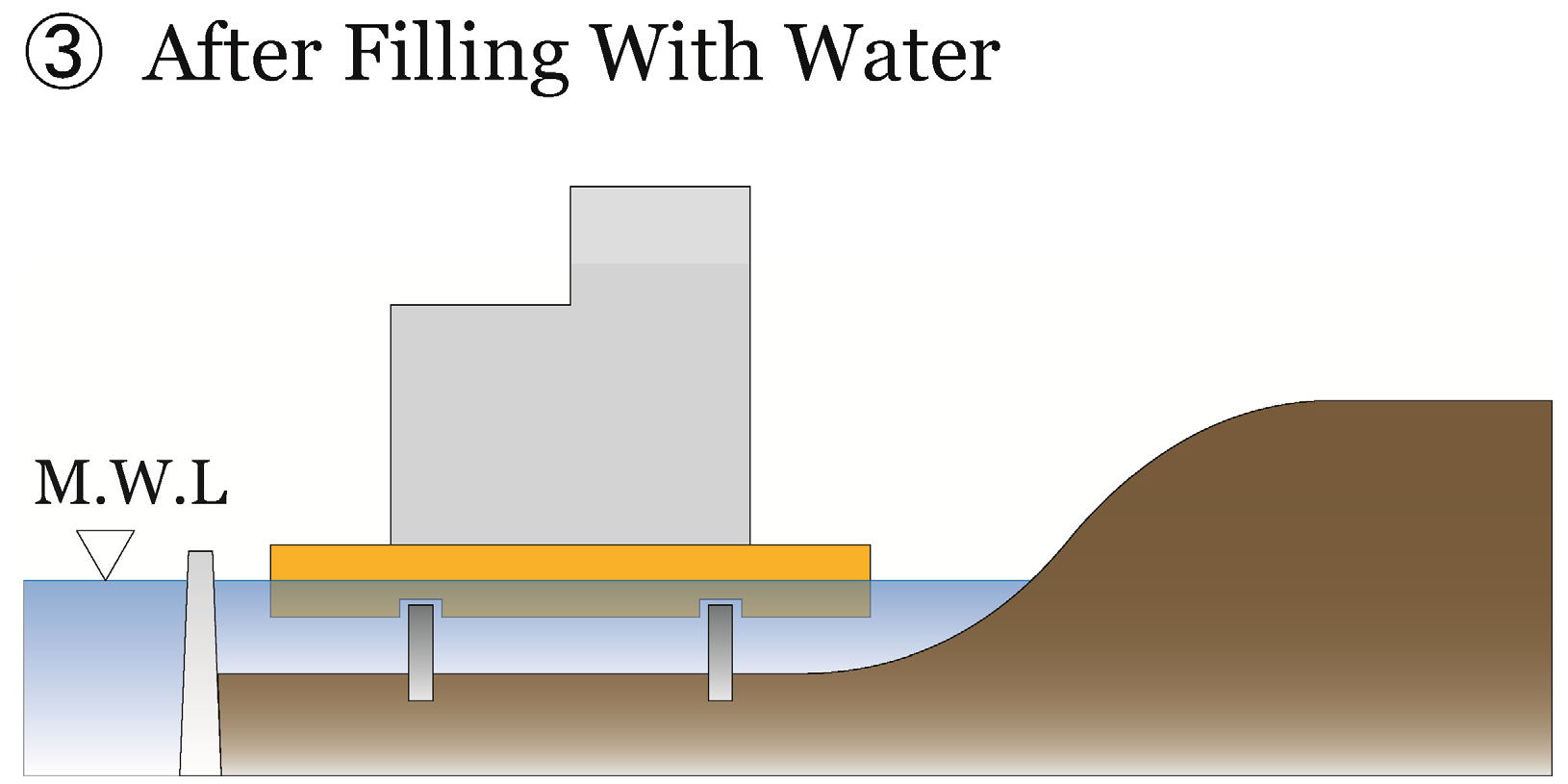
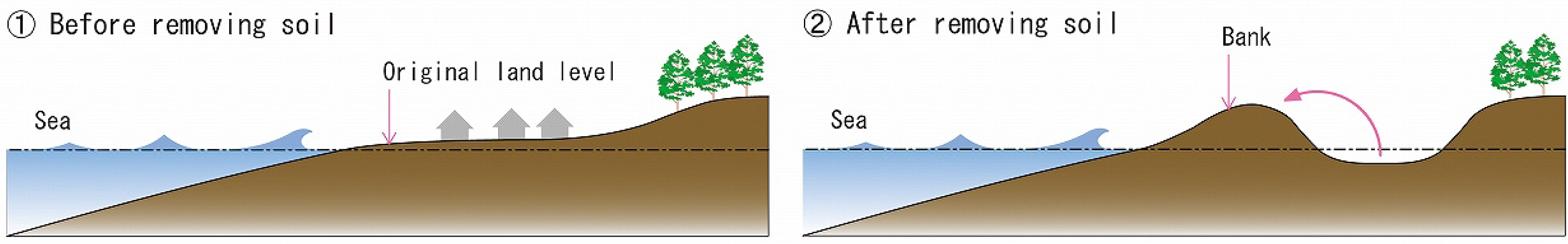
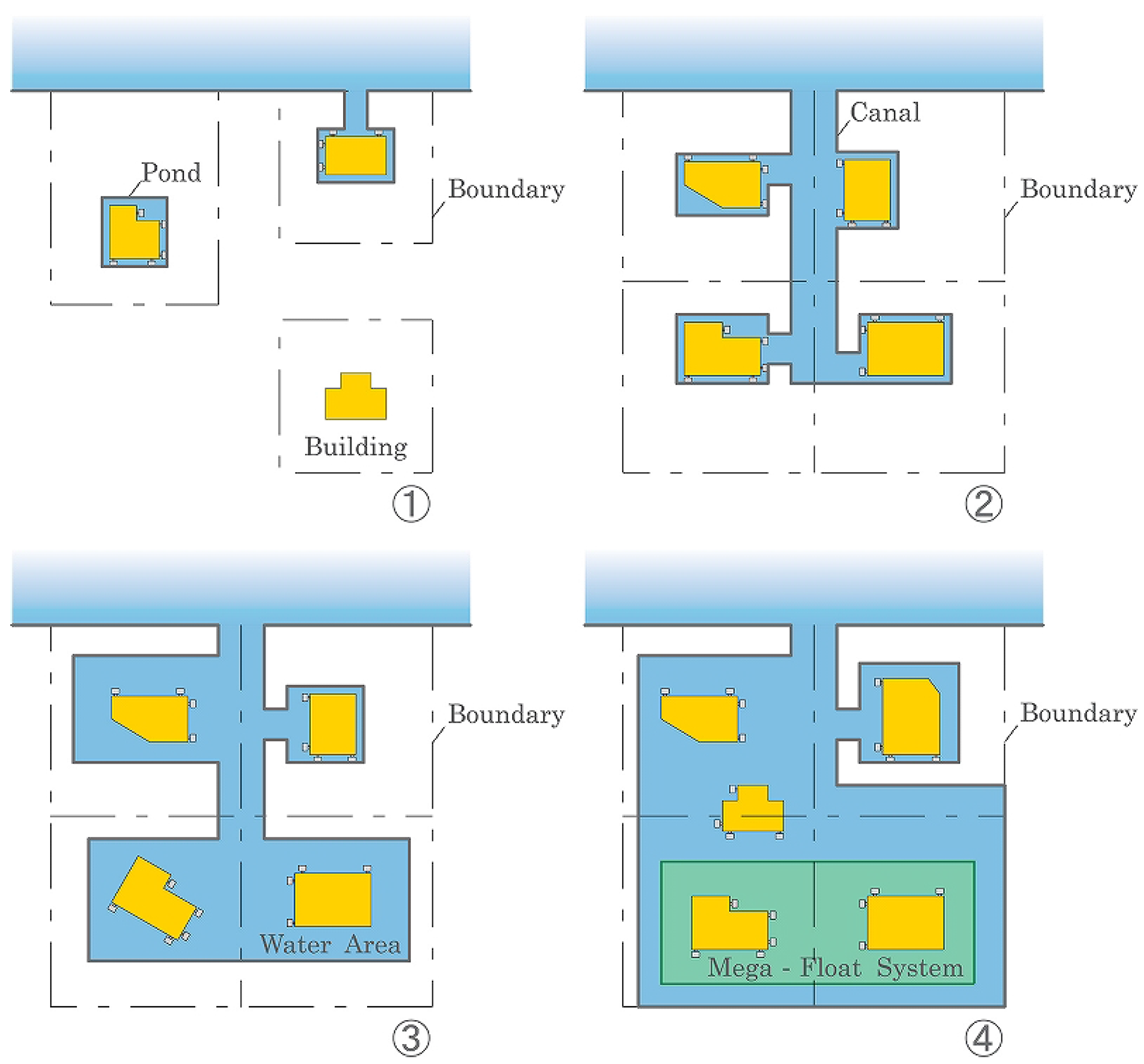
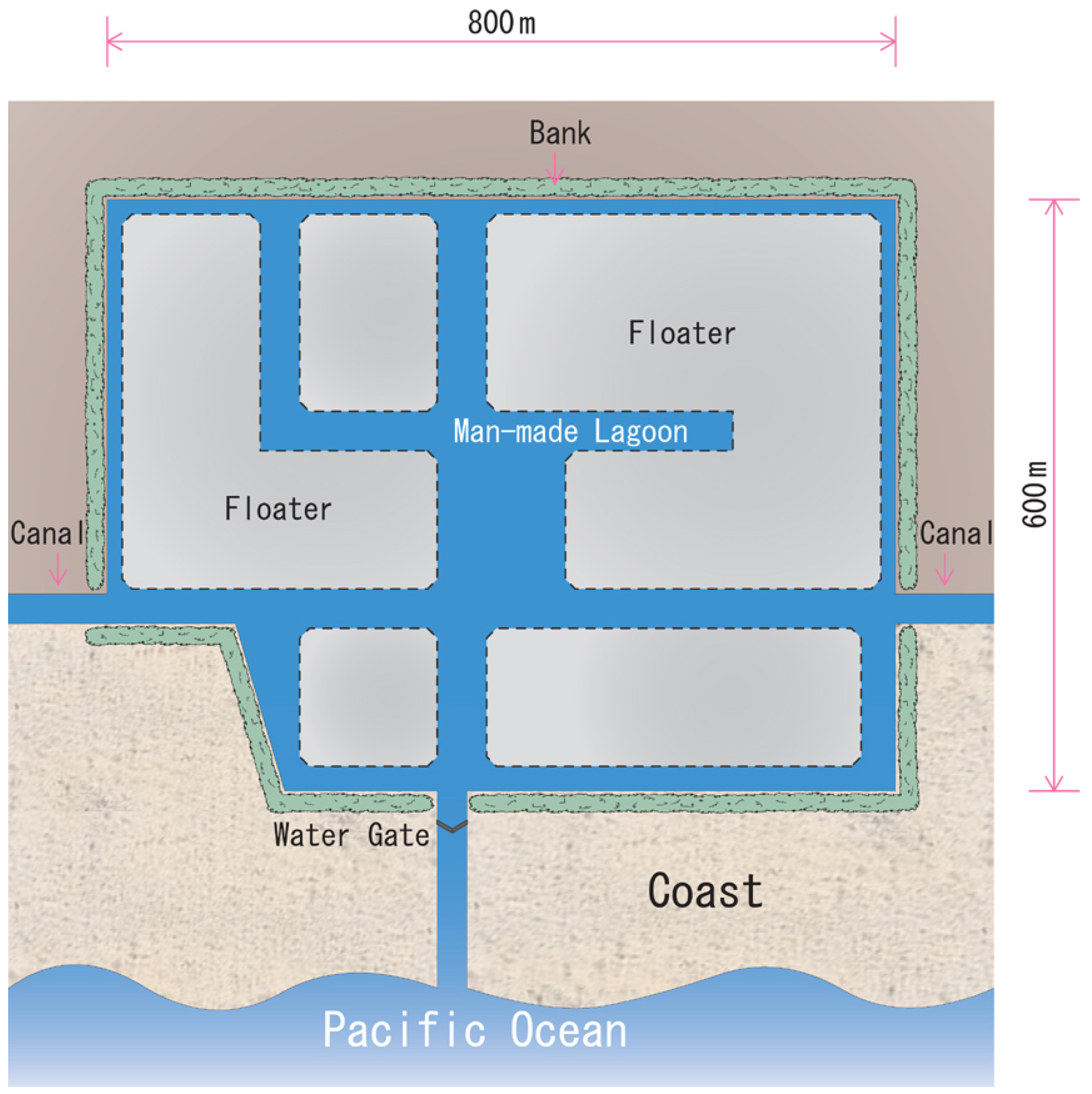
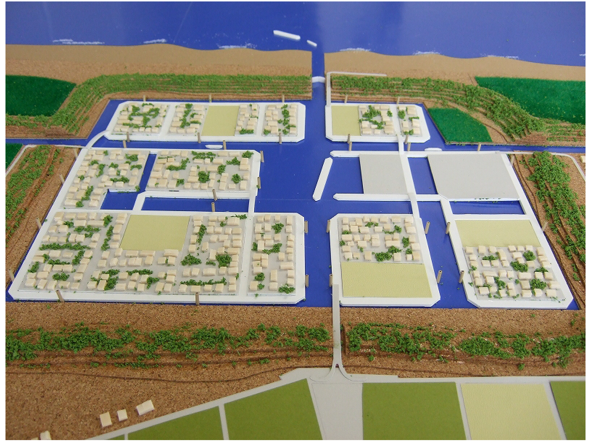
First of all, as is shown in Figure 14, this narrow bay area divided into eight district blocks is to be excavated to a depth of 5 m and the topsoil removed. The total area for this wide-ranging region along the bay, which is developed by excavating soil from low-lying land areas, is approximately 30,000 m2.; the topsoil of about 150,000 m
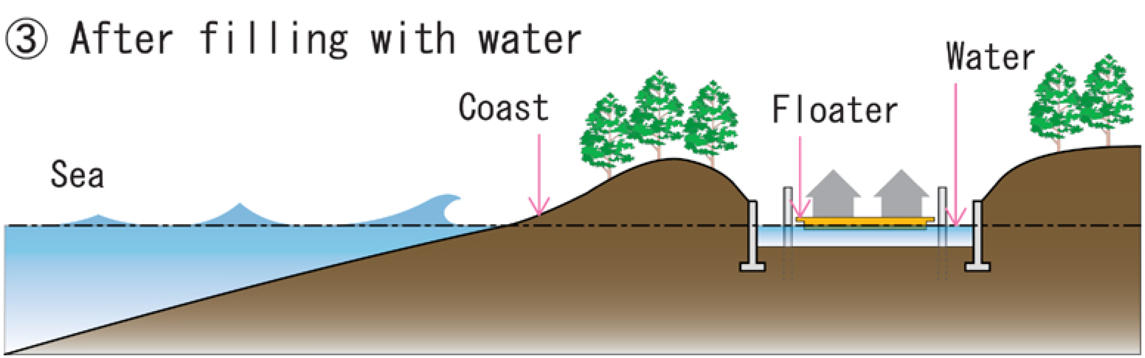
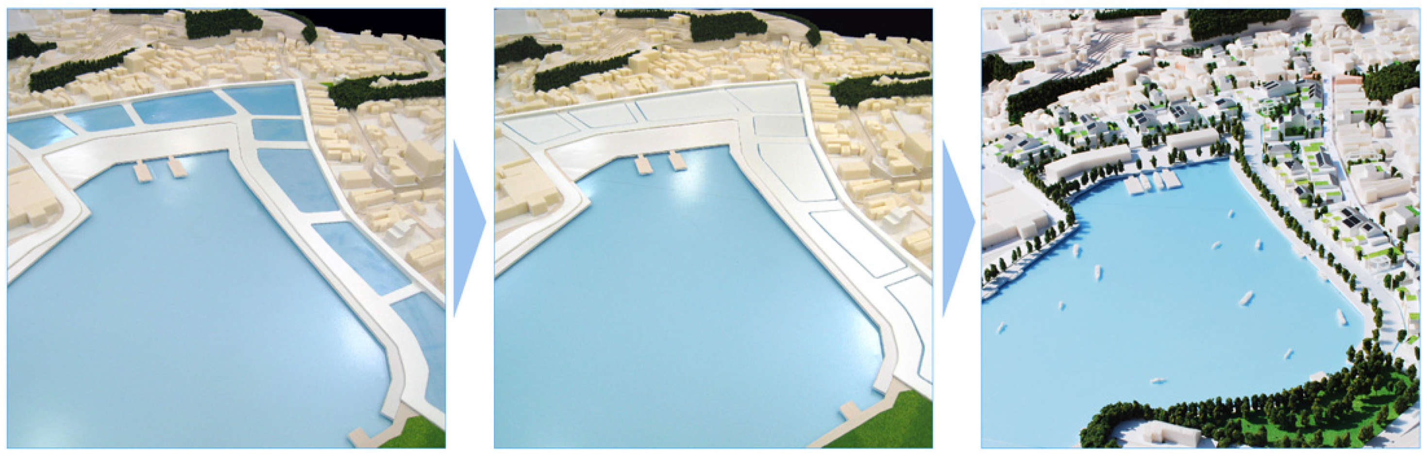
3 removed from the location is to be relocated in order to raise the other area where the ground had sunk by more than 80 cm due to the huge earthquake in 2011 with the excavated area being filled with water until a man-made lagoon and/or basin is produced. Secondly, eight floating platforms (Site 1 to Site 8) will be built at the shipyard and towed and situated inside the man-made lagoon. The construction process of the Kesennuma Bay area is shown in Figure 15. The left portion in this figure shows the condition of the 8 excavated areas with water and the floating platforms are situated at these water areas shown in the central figure. Meanwhile the one on right is the final stage of the reconstruction process for the destroyed Kesennuma Bay area. These floating platforms in 8 district blocks range in size and shape but due to this paper’s limited length, Site 2 floating platform which is seen having stability issues which are considered to be the worst upon facing natural disasters was selected as a representative platform among the 8 floating platforms for the foregoing study.
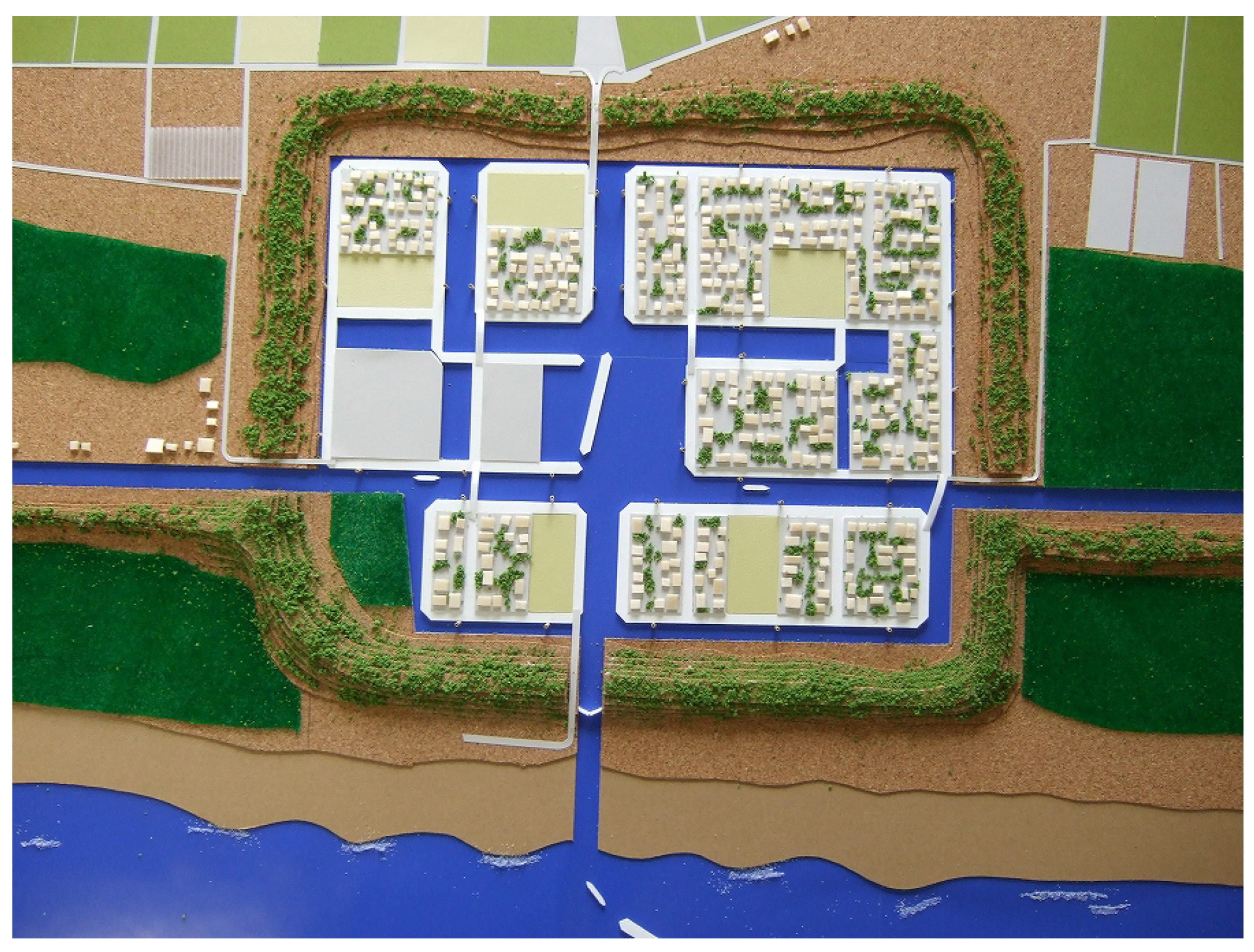
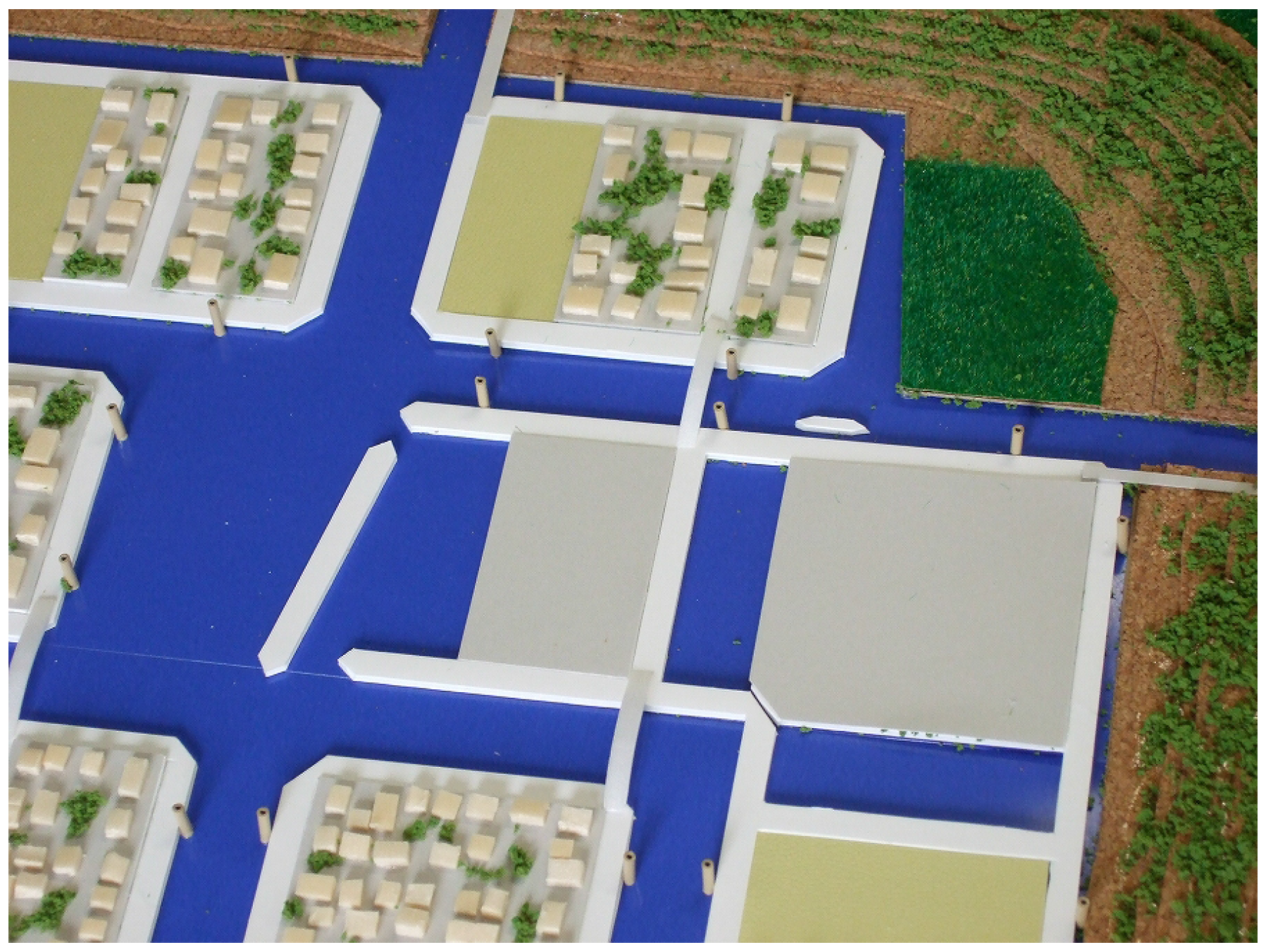
Figure 14. Site plan of eight district blocks in Kesennuma Bay area.
Jmse 03 00520 g014
Figure 15. Different construction stages of Kesennuma Bay area.
Jmse 03 00520 g015

4.2. Structural Design of Floating Platforms for Kesennuma Bay

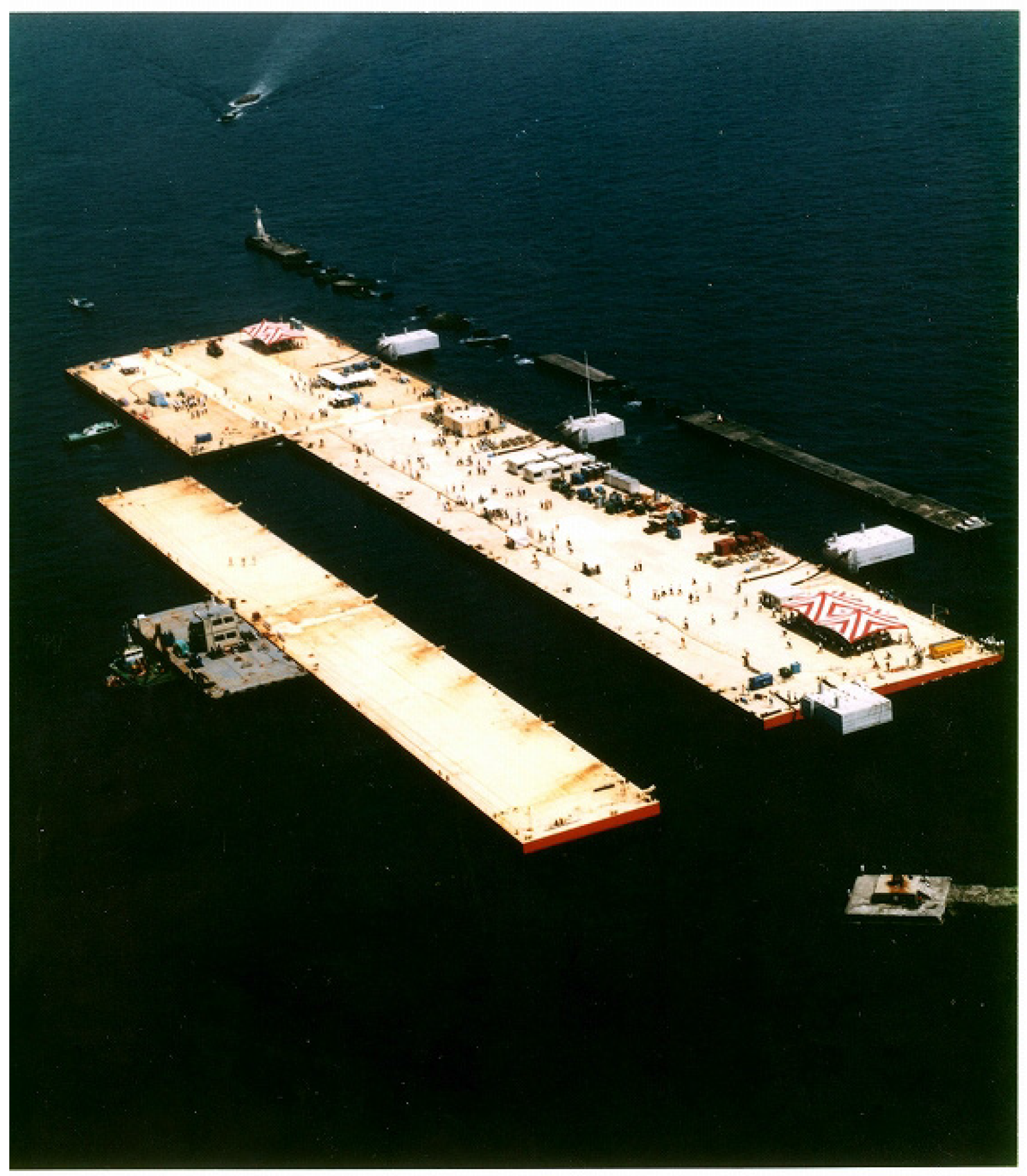
The floating platform in the proposal is of a barge-type construction, similar to that used in the Mega-Float Project that was carried out in Japan between 1995 and 2000 [12]. During the 1990s, attempting to realize facilitated construction of an offshore airport, the Technological Research Association of Mega-Float (TRAM) was established and centered upon the Japanese shipbuilding industry. In the final stage of this research project, a 1000-meter-long floating airport model was actually built and floated on the sea. The construction procedure of such a super-large floating platform had been constructed by welding many pieces of floating modular unit at sea and was verified successfully (see 
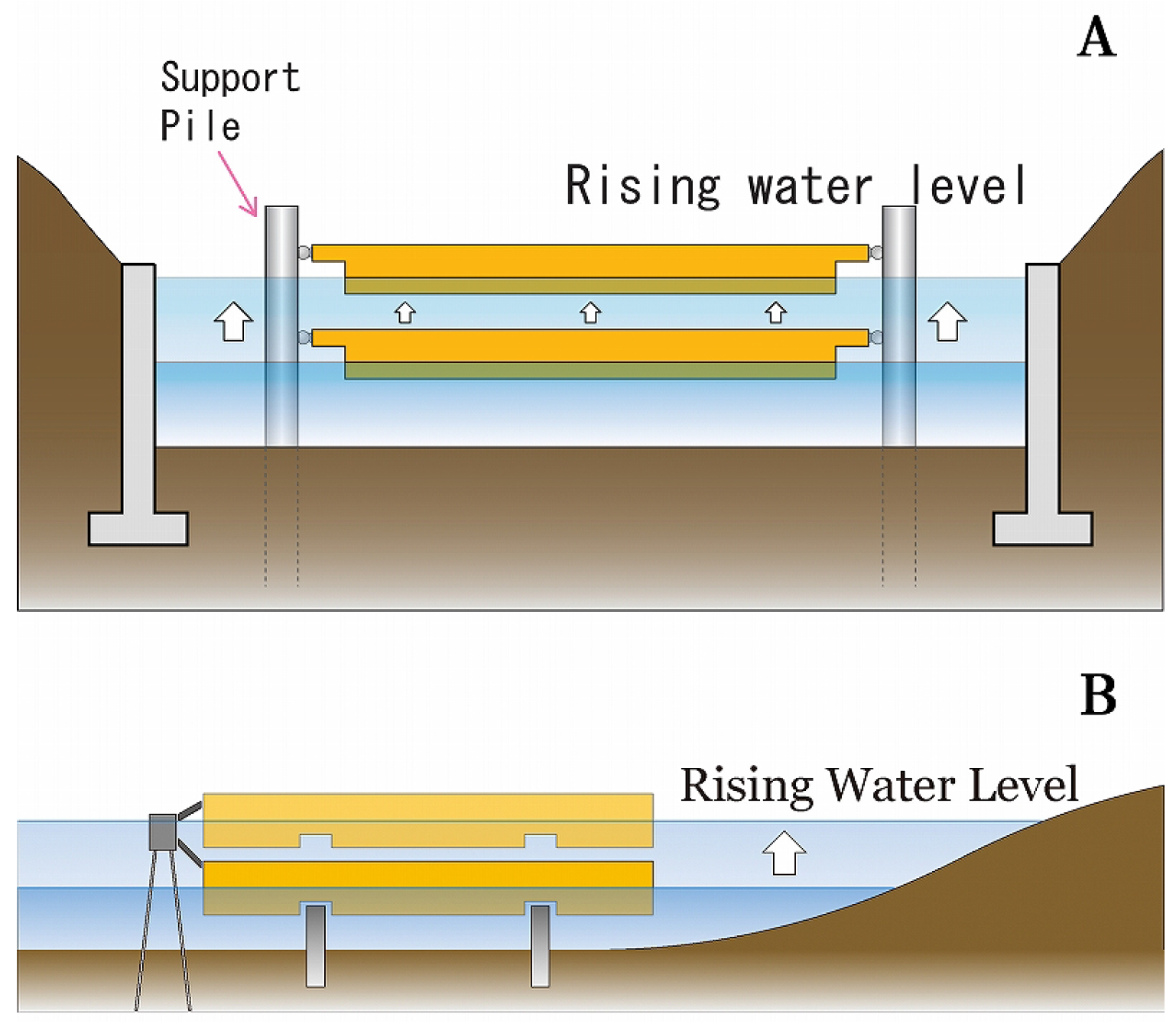
Figure 16). The authors are considering how to make best use of the valuable data and findings of the experiments as well as development of construction techniques for the project. In principle, the floating platform “floats by itself”; however, the proposal calls for what is known as the “Soft-landing System” explained already in Section 2. In this system, the floating platforms are partially supported by support piles located beneath them. Since a floating platform stays afloat independently, it can be freely and easily moved in the horizontal direction within the man-made lagoon and, when connecting the floating platform and its supporting piles, vertical adjustment can be precisely controlled through changes in the weight of the ballast water inside the floating platform.
Figure 16. Picture of “Mega-Float Project” (courtesy of the Marine Technology and Development Dept. at the Shipbuilding Research Center of Japan).
Jmse 03 00520 g016
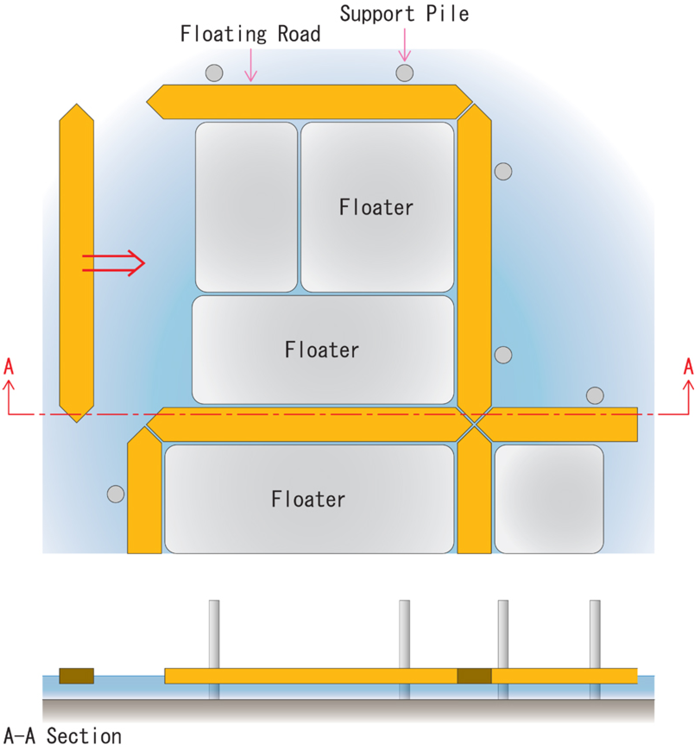
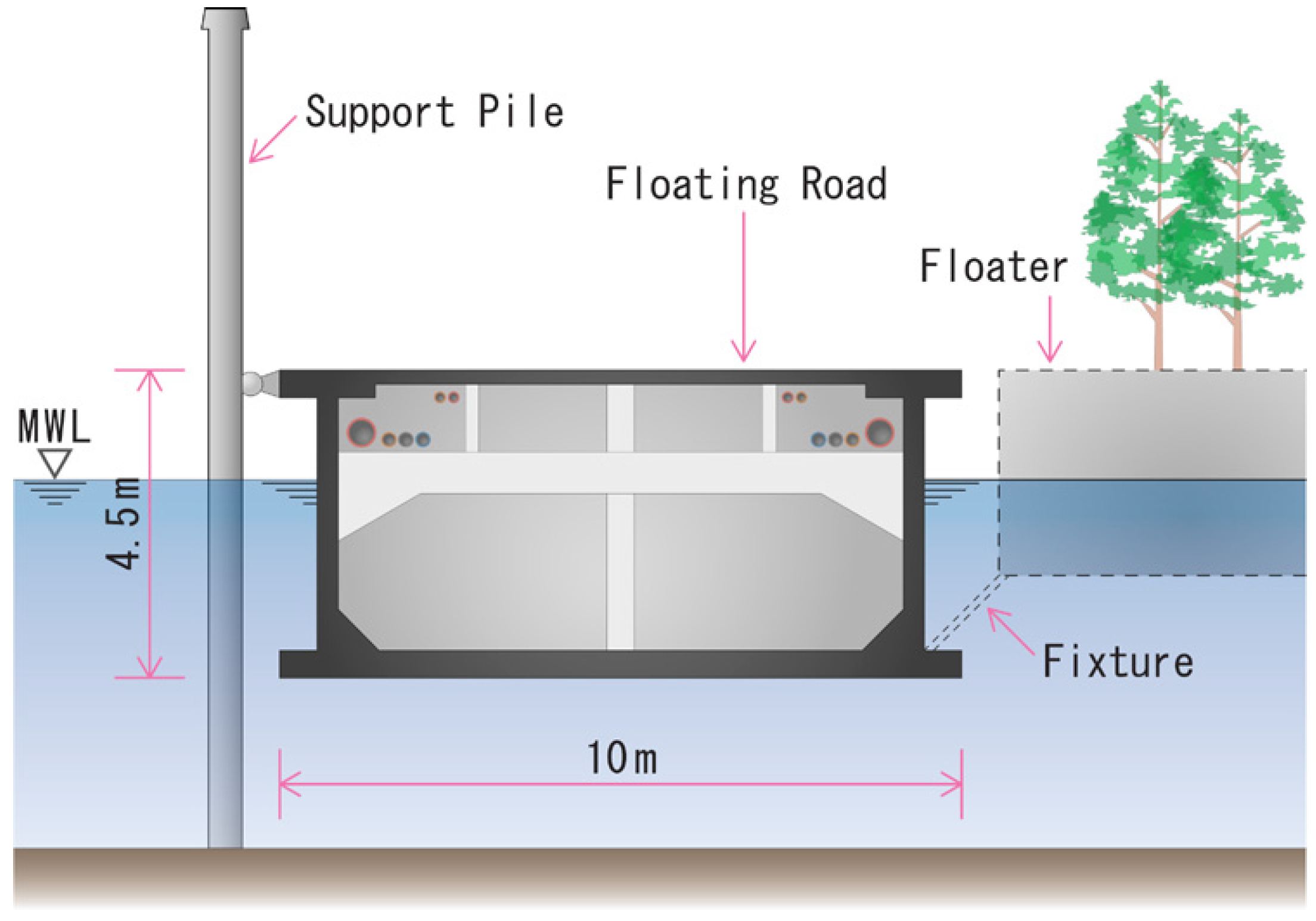
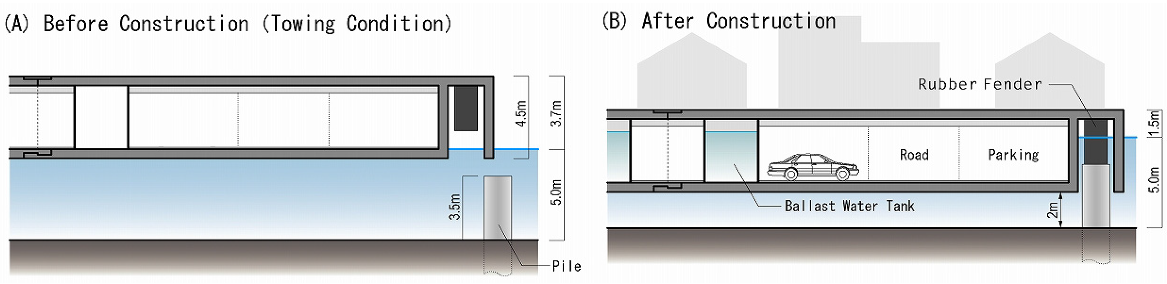
Figure 17 explains the simplified construction scheme for both the towing condition of the floating foundation without the ballast water as well as the fixed condition on the supporting pile (after filling water inside of the ballast water tank, following construction). The detailed section of the floating platform for “Soft-landing System” is shown in 
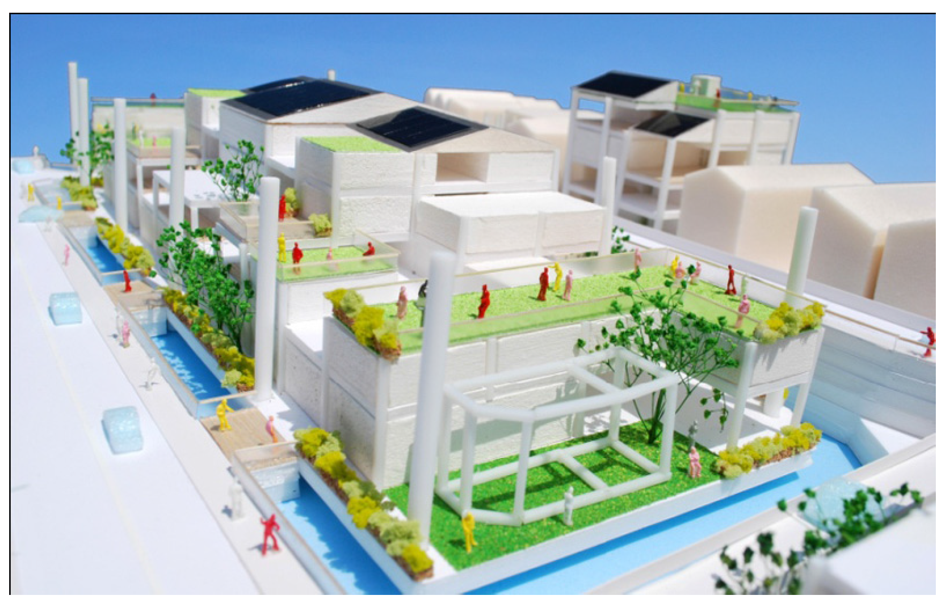
Figure 17 (right portion). The floating platform is partially supported in its weight by 3.5 m piles with rubber fenders. The rubber fender located underneath of the floating platform works to cushion from the earthquakes and so on. About one tenth of the floating complex’s total weight is placed upon the supporting pile in this case. Meanwhile, the buoyancy force supports the displacement of the floating complex the most. Bird’s-eye view of a floating complex in Site 2 of the Kesennuma Bay area is shown in Figure 18. The plan view of the Site 2 floating platform is basically trapezoidal in shape (27 m in width and 72 to 76 m in length) and the total deck area is 2175 m2. Since the draft is fixed to be 3.8 m, the volume and the displacement become 8265 m3 and 8265 t, respectively. In this calculation, it is assumed that the density of liquid is to be 0.001 t/m3 assuming the liquid inside of reservoir is treated as pure water rather than saltwater. Saltwater can also be used to fill this artificial basin. In case the basin is connected directly to the sea, the floating platform may move up and down due to the tidal change in vertical direction.
Figure 17. Sectional views of the conditions of floating platform both before and after constructions.
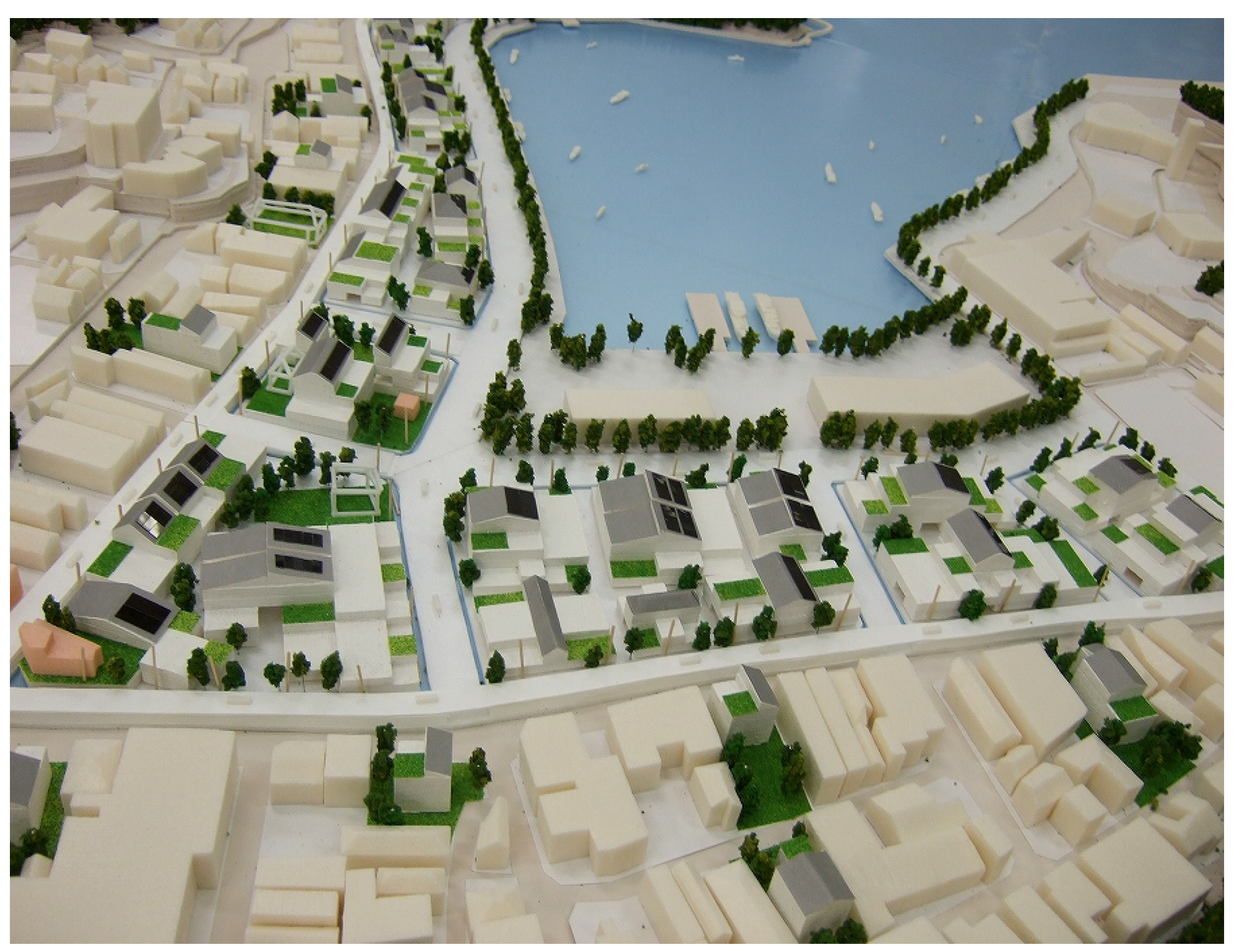
Jmse 03 00520 g017
Figure 18. Bird’s-eye view of the Site 2 floating complex (Image as represented by architectural model).
Jmse 03 00520 g018
On the other hand, the figure of 0.167 t/m3 is used for the calculation of the approximate deadweight of a floating platform made of steel as estimated as 1816 t from data provided by the Mega-Float Project. The estimated weights for a 4-story commercial complex with residences becomes 6238.9 t according to the data of 1.48 t/m2 for a reinforced concrete building for residential use due to the fundamental study while the live load of items such as trees, asphalt and cars is assumed as 200 t in this study. Moreover, since this live load varies depending upon quantity, materials and so on, the design enables the adjustment of one-fifth of the total live load by regulating the volume of ballast water inside floating platform. Since approximately one-tenth of the total weight is designed to be supported by several support piles of “Soft-landing System” as described before, the final total weight of the Site 2 floating complex becomes 9309 t instead of 8265 t, which is supported by the buoyancy force of the floating platform itself while the supporting piles support 1044 t in weight (under this condition, the weight of ballast water is 1054.1 t). Accordingly, the draft of the floating platform increases to be 4.28 m instead of 3.8 m when the floating platform detaches from the support piles. In another words, the floating platform stays on the same position as long as the water tide goes up more than 0.48 m from the mean water and/or sea level (MWL).

4.3. Some Engineering Evaluations on Floating Complex

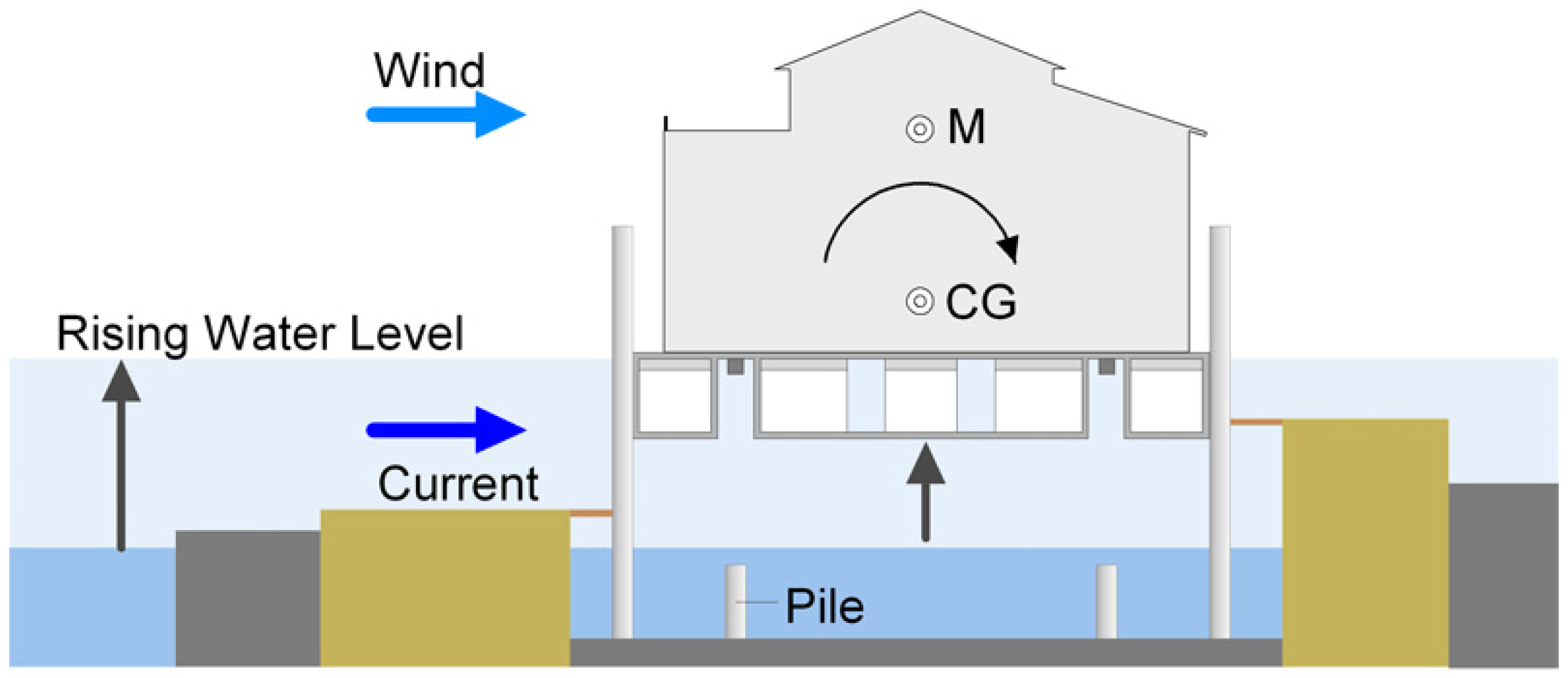
Usually, waves are treated as most influential upon causing excitations for the floating platforms at sea, wind and current forces are dominant upon analysis in the present case since waves lose most of their energy in shallow waters, being blocked by the surrounding land. Therefore, the wave force can be neglected for the present case. The schematic sectional view of the Site 2 floating complex against wind and current loads is shown in Figure 19. In this figure, CG indicates the location of the center of gravity while M is the location of the metacentric height of the floating complex. The floating complex moves up due to increased water depth in this figure. In general, both wind and current drag forces are calculated by multiplying four components: namely the liquid density, the projected area perpendicular to the flow, the drag coefficient and the square of the flow speed; this is divided by two. First of all, the current force due to tsunami, storm surge and/or wind driven current on the floating platforms was taken into account as dangerous factor. However, in principle, the horizontal load of the current due to tsunami on a barge-type floating platform is not too large, since the floating platform’s aspect ratio (draft-length ratio) is small. In other words, both the drag coefficient for the underwater portion of the floating platform and the wetted projected area are small. In addition, most of the tsunami flow passes underneath the floating platform, which is just riding on tsunami flow. Actually, video of the floating sea berth struck by the huge tsunami on 11 March 2011 have been recorded (available via YouTube) depicting the floating sea berth, “Marine Gate Shiogama”. This visual record proves that floating platforms moored properly are extremely stable and safe against tsunamis. The tsunami had not risen quickly (estimated about 0.04 m/s from footage) but even if it had a 10 m wave height, the vertical excursion of the floating sea berth, the vertical speed is only about threefold this speed at most, not that fast. The total horizontal load for tsunami against the Site 2 floating platform and 12 m high concrete piles is estimated as 1701 t (or 16,670 KN) based on the assumption that the horizontal velocity is 10.0 m/s observed at the water depth of 10 m on land during the huge tsunami in the Indian Ocean in 2004. Here in above calculations of the horizontal current force on the wetted portion of the floating platform, we assumed the drag coefficients of the wetted part of the floating platform as 1.0 for current force due to tsunami while the aspect ratio between the draft and the length of the floating platform is 1:20 [13].
Figure 19. Schematic sectional view of upright condition of the floating complex.
Jmse 03 00520 g019
Another environmental load is wind force and the resulting moment especially in the storm condition. Next, the inclination of floating complex due to the strong wind force must be determined for the safety of the floating complex. Basically, two factors are involved for the computation for the inclination of the floating complex; one is the overturning moment due to wind force and the other is the stability of the floating complex. The overturning moment due to wind or the wind heeling moment is obtained as a product of the wind force and the corresponding lever arm between the centroid of the wind force on the floating complex and the location of center of gravity. The vertical location of center of gravity of the Site 2 floating complex with ballast waters is calculated to be 8.08 m (vertical distance between the bottom of the floating platform and the location of CG) while the meta-centric heights (vertical distance between CG and the location of M) in transverse and longitudinal directions for the Site 2 floating complex are 10.22 m and 99.26 m, respectively. Meanwhile the restoring moment against the wind heeling moment is calculated as a product of the displacement of the floating complex, and the meta-centric height and the heeling angle assuming the angle is small enough. Then the heeling angle due to wind can be obtained by these relations. When the wind-speed is assumed to be 70.0 m/s which is close to be 69.8 m/s, this maximum in Japan having been reached during a typhoon at the Muroto Peninsula of Kochi Prefecture in September of 1965, the approximate horizontal wind load and the heeling angle of the floating complex in the transverse direction are calculated as 295.9 t (or 2899.5 KN) and only 0.569 deg., respectively while heeling angle of longitudinal direction is less than one tenth of that of transverse direction, thus showing that there is a small effect generated due to strong wind. Here in above calculations of the horizontal natural load on the structure, we assumed the drag coefficients as 1.5 for wind.

5. Concluding Remarks

In general, many cities in low coastal areas in the world are located at low-lying ground below sea level. These locations are potentially hazardous in that they are risk-prone in terms of natural hazards due to their proximity to seas and/or rivers. By applying lateral thinking, the weakness inherent in such locales can be transformed into strength, offering protection against water-related hazards by rethinking the way people live in such areas, that is by constructing buildings on floating platforms in calm man-made lagoons or basins rather than on land near the sea and/or river. Costs will not be prohibitive since it is less costly to excavate soil in low-lying lands at sea level because the amount of soil to be removed is small and soil can be reused around near land areas. Our concept, which suggests excavation of low-lying land areas to realize a large reservoir in the middle of cities and/or the coastal areas to place a semi-floating platform therein, also seeks to produce a man-made foundation as well as artificial floating platforms atop it in order to make effective use of the space above the body of water and there produce a living space on the floating platform [14,15]. However, we also do accept that floating platforms should somehow be protected, the reason being not the direct horizontal forces of storm surges, tsunamis and/or wind-driven currents on floating platforms, but the flotsams produced by storm surges, tsunamis and so on. Our solution combines the countermeasures of an artificial reservoir and a floating platform applied as a Soft-landing System [16].
In the theoretical estimations of natural hazards presented in this paper, we have introduced the engineering studies of the strong current force due to tsunami and highest wind force in typhoon conditions, acting on the floating complex independently. However, concerning the serious storm surge due to huge typhoon and/or hurricane, both these highest components may hit the floating complex simultaneously. Furthermore, violent impact loading due to the breaking waves could also strike the floating complex, in addition to these two components. Although this situation seems hopeless, we still believe that our floating platform system can overcome these heavy conditions by, for example, the reinforcement of the supporting piles, additional technical and/or operational devices and so forth. On the other hand, from a realistic standpoint, the probability and/or risk that the coexistence of the extreme values of both wind and current forces—with the maximum wave breaking force appearing at same time—is considered to be extremely small, something near impossible. However, we do agree that more studies on the combined loading conditions of various highest natural elements together on the floating platform system are very important and need to be carried out as the next step.
In this paper, we first present a novel solution as ways of transforming dangerous low-lying areas into those safeguarded against such hazards. Secondly, utilization of the “floating platform” as secure base for society to build atop this new artificial reservoir is introduced. Furthermore, possible applications of our concept are introduced for the reconstruction of the Kesennuma Bay area as well as the destroyed coastal area of Arahama by huge tsunami in northeast Japan on 11 March 2011 (see Figure 20 and Figure 21).
As a conclusion, we show that the floating platform is useful especially in low-lying land area in cities and/or near coastal areas by showing some engineering studies as well as the fact “Marine Gate Shiogama” survived. We believe that similar coastal and harbor system works very well not only for this reconstruction scheme but is also applicable for isolated islands such as Tuvalu, Maldives and so on suffering from storm surges, tsunamis and other hazards due to global warming.
Figure 20. Bird’s-eye view of reconstructed Arahama coastal area (Image as represented by architectural model).
Jmse 03 00520 g020
Figure 21. Bird’s-eye view of reconstructed Kesennuma Bay area (Image as represented by architectural model).
Jmse 03 00520 g021

Acknowledgments

The authors are grateful to Hironori Sugimoto, general manager of Marine Technology & Development Dept. at the Shipbuilding Research Center of Japan, for disclosure of various practical data concerning with the Mega-Float Project. In addition, the authors especially thank Umekazu Kawagishi, College of Industrial Technology of Nihon University with his students, and Hirofumi Sugimoto, Dept. of Architecture, Miyakonojo National College of Technology for cooperation upon the designing of the floating complex for Kesennuma Project, as regards architectural and urban design/city planning. In addition, finally, the authors appreciate Kenzo Nakajima, a designer at ARCHIPARTNERS, Inc. (Tokyo, Japan), for providing illustrations used in this paper.

Author Contributions

Toshio Nakajima conceived the general concept of the paper, and wrote the manuscript. Motohiko Umeyama wrote a part of the manuscript, and supervised and rearranged the paper.

Conflicts of Interest

The authors declare no conflict of interest.

References

  1. Intergovernmental Panel on Climate Change IPCC. Fifth Assessment Report—Climate Change 2014; Intergovernmental Panel on Climate Change: Geneva, Switzerland, 2014. [Google Scholar]
  2. Bender, M.A.; Knutson, T.R.; Tuleya, R.E.; Sirutis, J.J.; Vecchi, G.A.; Garner, S.T.; Held, I.M. Modeled impact of anthropogenic warming on the frequency of intense Atlantic hurricanes. Science 2010, 327, 454–458. [Google Scholar] [CrossRef] [PubMed]
  3. Umeyama, M. Shore protection against sea level rise and tropical cyclones in small island states. Nat. Hazards Rev. 2012, 13, 106–116. [Google Scholar] [CrossRef]
  4. Nakajima, T.; Iijima, K.; Inoue, K.; Inoue, S.; Kagemoto, H.; Hara, S. On the planning of a very large floating structure. In Proceedings of the 16th Ocean Engineering Symposium, Society Naval Architects of Japan, Tokyo, Japan, July 18–19 2001; pp. 221–228.
  5. Ymamashita, Y.; Yonezawa, M.; Shimamune, S.; Kinoshita, Y. Joining technology for construction of very large floating structures. In Ocean Space Utilization Technology; Ministry of Land, Infrastructure and Transport of Japan: Tokyo, Japan, 2003; pp. 253–260. [Google Scholar]
  6. Marine Gate Shiogama. Available online: https://www.youtube.com/watch?v=htYaz909e48.
  7. Nakajima, T.; Umeyama, M.A. Proposal for a Floating Urban Communities in the Man-made Inlets. In Proceedings of the International Symposium Sustainable Urban Environment. (ISSUE2007), Grad. School of Urban Environment. Sc., Tokyo Metropolitan University, Tokyo, Japan, 9–10 November 2007; pp. 27–33.
  8. Nakajima, T.; Umeyama, M. Floating Cities as a Solution to the Escalating Sea Level Rise in Lower-Lying Land Areas. In Proceedings of the Regional Conference Environment & Earth Resources, Kuantan, Malaysia, 7–8 December 2009; pp. 261–269.
  9. Nakajima, T.; Umeyama, M. Water city as solution to escalating sea level rise in lower-lying areas. In Proceedings of the Oceans-San Diego 2013 MTS/IEEE International Symposium, San Diego, CA, USA, 23–27 September 2013; pp. 1–9.
  10. Nakajima, T.; Shintani, T.; Umeyama, M. A New Concept for Lower-lying Land Areas and Coastal Villages Safe from Natural Disasters. In Proceedings of the Oceans 2011 MTS/ IEEE International Symposium, Kona, HI, USA, 19–22 September 2011; pp. 1–10.
  11. Nakajima, T.; Sugimoto, H.; Kawagishi, U.; Umeyama, M. A concept for water-based community to sea level rise in the lower-lying land areas—Toward reconstruction of coastline area in disaster-stricken northeast Japan. In Proceedings of the Oceans 2012 MTS/IEEE International Symposium, Hampton Road, VA, USA, 14–19 October 2012; pp. 1–9.
  12. Sato, C. Result of 6 years research project of Mega-float. In Ocean Space Utilization Technology; Ministry of Land, Infrastructure and Transport of Japan: Tokyo, Japan, 2003; pp. 436–442. [Google Scholar]
  13. Takai, R.; Hoshino, K. A Consideration on the Coefficient of Friction Drag and Viscous Damping of a Pontoon-type VLFS. In Proceedings of the 14th Ocean Engineering Symposium, Society Naval Architects of Japan, Tokyo, Japan, 16–17 July 1998; pp. 441–446.
  14. Nakajima, T.; Umeyama, M. Study on a Waterfront Urban Community in Lower-lying Land Areas. In Proceedings of the Techno-Ocean 2010 Intertional Symposium, Kobe, Japan, 15 October 2010; pp. 14–16.
  15. Nakajima, T.; Umeyama, M. A new concept for the safety of low-lying land areas from natural disasters. J. Ocean Eng. Mar. Energy 2015, 1, 19–29. [Google Scholar] [CrossRef]
  16. Sustainable Water City. Available online: http://www.waterpolitan.com.

