1. Introduction
Substituting fossil fuels with renewable forms of energy has become a promising option to face the increase of greenhouse gas concentrations in the atmosphere and the rising cost of oil [
1]. This context has motivated the shift to biomass for heat production since it offers many economic, social, and environmental benefits such as financial net saving, local employment opportunities and carbon dioxide (CO
2) emissions reduction compared to petroleum products [
2]. In rural areas, there is a growing interest in using agricultural residues and energy crops grown on underutilized lands for heating farm facilities [
2,
3,
4]. The latter represent moreover several ecological benefits including prevention of soil erosion, limited soil management, and low demand for nutrient inputs [
5]. Although combustion is the most mature technology for biomass conversion, emissions from agricultural biomass combustion are generally greater than those from combustion of woody materials, which are the most common solid biofuels. Actually, agricultural biomass burned in small-scale appliances can significantly contribute to higher pollutants release such as particulate matter (PM), nitrogen oxides (NO
x), sulfur dioxide (SO
2), and hydrogen chloride (HCl) [
6]. These contaminants can affect air quality and climate by causing respiratory and cardiovascular problems, acid rains, and absorption of solar radiation [
7,
8].
Comparatively to wood, typical agricultural fuels have higher ash content and higher concentrations of inorganic elements such as nitrogen (N), sulfur (S), chlorine (Cl), potassium (K), and silicon (Si). High amounts of N, S, and Cl in energy crops increase the emissions of NO
x, SO
2, and HCl, respectively. Ash is responsible for dust production and operational problems such as fouling, slagging, and corrosion, which may disturb the burning process, reduce efficiency and lead to unwanted shutdowns and higher levels of compounds from an incomplete combustion including carbon monoxide (CO) and PM [
9,
10]. Particles consist of aerosol-forming elements like K and Cl, as well as sodium (Na) and S. Boiler corrosion and fouling are also directly related to alkali metals (K and Na) and Cl contents. Chlorine acts as a catalyst, facilitating the movement of iron away from metal surfaces and the deposition of inorganic compounds. Sulfur and Si, in combination with alkali, lead to reactions associated with fouling and slagging in boilers. Potassium and, to a lesser extent, Si, S, and Na, contribute to lower ash melting temperatures in dedicated energy crops [
11,
12,
13,
14,
15].
Strategies which can be used to reduce pollutants release from agricultural biomass combustion include the use of air staging [
16] or flue gas cleaning devices such as filters and electrostatic precipitators [
6]. Since the primary cause of emissions is the elemental composition of the feedstock, an alternative, which does not imply possible modifications to the heating system and can act on ash-related problems, is modifying the biomass chemical properties through the use of additives or fuel blending [
17]. Additives refer to a group of minerals or products that can alter the ash chemistry, convert problematic species to less troublesome forms and enhance the ash melting temperature in thermal processes. Additives can be introduced before combustion by blending them with the fuel prior to pelletizing the admixture produced [
18]. Based on their reactive compounds, additives can be classified as aluminum silicates, calcium, or sulfur based additives [
17,
18,
19].
Aluminum (Al) silicates based additives, such as kaolin, have been exhaustively studied and have shown an ability to abate particle emissions [
11,
17,
20,
21,
22,
23,
24] and ash sintering [
25,
26,
27] during combustion of agricultural crops and residues. Kaolin mainly acts by binding alkali compounds in ash and by forming K- or Na-Al silicates that have a higher melting temperature than pure K or Na silicates [
17,
18,
19]. Some works [
20,
23,
28,
29] also reported that the addition of kaolin almost eliminated Cl in fly-ash particles whereas HCl levels raised. As clay minerals additives, sewage sludge contains great amounts of Al-Si compounds, can increase ash sintering temperature and can reduce fouling deposition [
18,
30]. In addition, it has been suggested that S, Ca, and phosphorus (P) comprised in sewage sludge may contribute to the capture and deposition of gaseous alkali chlorides (KCl or NaCl) [
30,
31,
32]. In fact, these gases can be transformed into sulfates, which are less deleterious deposits [
31], or into high melting K- or Na-Ca phosphates [
18,
19,
30]. Additives from waste stream resources such as sewage sludge are of particular interest since they are financially attractive [
30]. Calcium based additives, such as lime and limestone, are used for reactions with HCl and SO
2 and have been recognized as well as effective in reducing the slagging tendency in combustion systems by formation of high melting silicates formed of Ca, magnesium (Mg), and alkali [
18,
19,
20,
23,
26,
27]. Co-firing biomass with calcium based additives actually creates a diluting effect on biomass ash, which restrains physical contact and thus sintering of ash particles [
18,
19]. Furthermore, lime is already and widely used in agriculture since it is one of the most crucial and beneficial components to successful crop management [
33]. Sulfur based additives can decrease the formation of alkali chlorides through different sulfation reactions, as well as increase the melting point of deposits, hence preventing fouling of heat transfer surfaces [
18,
19]. For instance, the injection of ammonium sulfate greatly reduced gaseous KCl and produced sulfated deposits without any trace of Cl. Concentrations of SO
2 and HCl in flue gas were however higher when ammonium sulfate was added, while nitrogen monoxide (NO) emissions severely dropped because of selective non-catalytic reduction with ammonia (NH
3) [
34]. Another option as a sulfur-based additive could be lignosulfonate, which is a by-product of the wood sulfite pulping process. So far, lignosulfonates are used in animal feeds and have been considered as the most effective and popular binding agents for pellets [
35]. Their behavior and potential as combustion additives are uncertain since previous experiences showed that pellets with lignosulfonate result in problems with slag formation for wood [
36] as well as in an anti-slagging effect for barley straw and husk [
37].
Besides the addition of additives, mixing problematic feedstocks with good quality fuels, such as woody materials, may also improve thermal process and reduce emissions. The positive impact may be based on the diluting effect of the fuel having a lower ash content [
18,
38,
39]. The burning of a blend composed of reed canary grass and wood chips only slightly raised fine particles, NO
x and SO
2 releases compared to wood alone, while CO and HCl either decreased or remained unchanged [
38]. Nevertheless, different results from Lamberg
et al. [
39] showed elevated levels of incomplete combustion gases using similar wood-grass pellets.
This short review suggests that sewage sludge, limestone, lignosulfonate, and wood could be used as additives for mitigating particulate and gas emissions as well as ash-related operational problems in agricultural biomass heating systems. However, there is currently only a few scientific studies regarding the capacity of these additives to abate pollutant formation and sintering of energy crop ash. The present work was performed with the aim of measuring and comparing PM and gas production and evaluating the ash melting propensity during small-scale combustion of reed canary grass with and without additive (sewage sludge, limestone, lignosulfonate, and wood). This energy crop has a great development potential in the province of Quebec, Canada, but its high concentrations of S, Cl, K, and Si are responsible for increased levels of contaminants and clinkers [
40]. The results obtained in this study can provide a better understanding of the effects of biomass-additive and biomass-biomass blending and their potential for controlling emissions and solving ash-related problems.
2. Materials and Methods
2.1. Biomass Fuels, Additives, and Blends
Pellets of reed canary grass and wood were respectively bought from agricultural producers (CLD Du Granit, Lac-Mégantic, QC, Canada) and a pellet mill (Trebio, Portage-du-Fort, QC, Canada). Both biomass fuels were milled (Wiley Mill 1885PL, Thomas Scientific, Swedesboro, NJ, USA) using a 4 mm screen size. Sewage sludge (Osons L’Osier, Rivière-du-Loup, QC, Canada) and lignosulfonate (Granulart, Neuville, QC, Canada) were acquired from research partners. Limestone came from a chemical company (Laboratoires MAT, Quebec City, QC, Canada). Lignosulfonate and limestone were in a powdered form.
The products were weighed on a dry basis and each of the individual blends (
Table 1) was mixed manually and then pelletized (GRH200 pelletizer, Granulart, Neuville, QC, Canada). Sewage sludge (SS), limestone (LM) and lignosulfonate (LG) were added to reed canary grass (R) in a percentage of 3 wt% (blends R-SS, R-LM and R-LG, respectively). A review of the literature [
10,
11,
20,
22,
24,
25,
26,
27,
29,
30] showed that additives are generally blended with biomass in proportions up to 10 wt%. However, satisfactory results were especially obtained by adding 1–5 wt% of additives. By analyzing available data, it seemed that the difference between 1 wt% and 3 wt% was slightly significant, whereas it was negligible between 3 wt% and 5 wt%. Wood (W) was blended with reed canary grass in a 50–50 wt% proportion (blend R-W). This choice of admixture was motivated through theoretical calculations which determined the optimal levels according to the guiding values of Obernberger
et al. [
9] on major components (N, S, and Cl) in solid biofuels for unproblematic combustion. Furthermore, pure wood and pure reed canary grass pellets were tested to serve as references.
Table 1.
Description of the tested blends (expressed in wt% of the different products).
Table 1.
Description of the tested blends (expressed in wt% of the different products).
| R | W | R-W | R-SS | R-LM | R-LG |
|---|
| Reed canary grass (R) | 100 | 0 | 50 | 97 | 97 | 97 |
| Wood (W) | 0 | 100 | 50 | 0 | 0 | 0 |
| Sewage sludge (SS) | 0 | 0 | 0 | 3 | 0 | 0 |
| Limestone (LM) | 0 | 0 | 0 | 0 | 3 | 0 |
| Lignosulfonate (LG) | 0 | 0 | 0 | 0 | 0 | 3 |
All blends were experienced only once because the availability of resources (biomass and additives) by the suppliers did not allow realizing more than one replication. Before each experiment, a sample of the tested blend was sent to the Research and Development Institute for the Agri-Environment (IRDA) scientific laboratory (Quebec City, QC, Canada) to determine the physico-chemical properties. A more detailed description of the laboratory methods used can be found in Fournel
et al. [
40].
Additionally, fuel indexes on a molar basis, based on works by Sommersacher
et al. [
27,
41] and describing the effect of given elements on alkali release, corrosion risk and ash sintering temperature, were calculated. They correspond respectively to Si/(K + Na), 2S/Cl and (Si + P + K + Na)/(Ca + Mg + Al). Herein, the sum of alkali (K + Na) replaced the K factor in the original indexes to account for possible high Na contents in some admixtures.
2.2. Combustion System
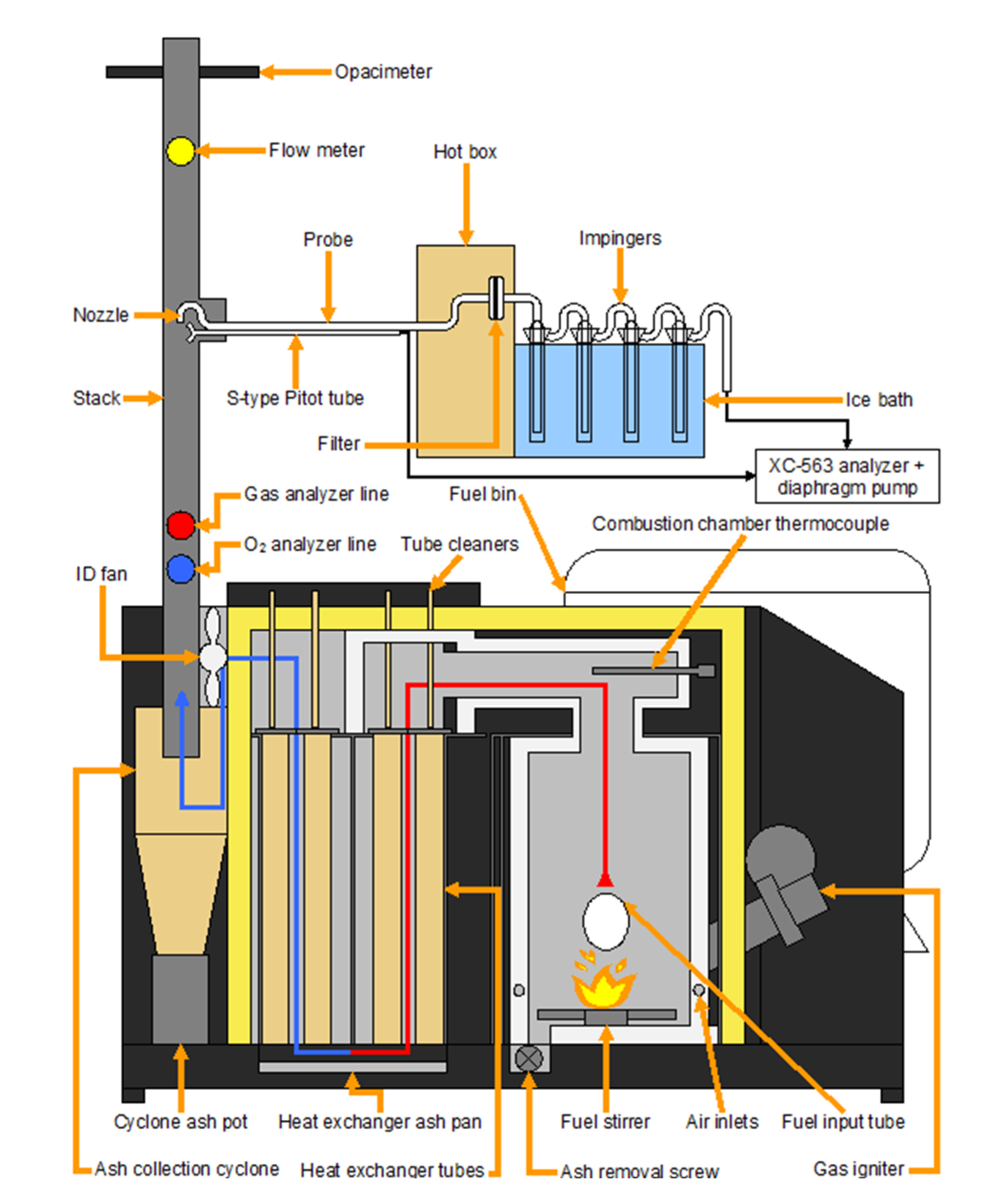
The experimental tests were carried out at a research facility on bioenergy of IRDA (Deschambault, QC, Canada). This facility includes a combustion room in which was installed a commercial 29-kW furnace (BB-100, LEI Products, Madisonville, KY, USA). The BB-100 (
Figure 1) is a top-fed, multi-fuel (wood, agricultural crops and residues, waste,
etc.), hydronic (use of water as the heat-transfer medium), non-catalytic, and non-pressurized boiler.
Figure 1.
Schematic view of the boiler component parts and main sampling instruments.
Figure 1.
Schematic view of the boiler component parts and main sampling instruments.
The combustion was initiated by using a propane igniter. After reaching the intended temperature, restricted to 675 °C in order to limit the formation of slags, the supply of fuel was instigated. The pellets were continuously supplied to the burning chamber from a storage tank by an auger screw. The overfed material which dropped into the combustion compartment from the fuel input tube was constantly mixed on the ceramic base plate by a fuel stirrer. This apparatus allowed a slow removal of ash to an ash tray in which an auger screw is installed. The air was supplied to the combustion chamber by an induced draft fan, located at the end of the flue gas stream behind the heat exchanger, which pulled up air from the outside inwards. The temperature, the supply rate of fuel and air as well as the frequency of ash removal were controlled by a user interface and regulated for each blend to reach a stable combustion regime, which was then sustained automatically by the boiler’s internal computer. The produced heat energy was extracted to the circulating water in a heat exchanger. The feed and hot water temperatures were respectively maintained at 60 °C (± 3 °C) and 70 °C (± 3 °C). Exhaust gases were directed to an exhaust duct via an ash collection cyclone. The boiler finally contains a removable ash pan and pot under the heat exchanger and the cyclone system.
About 25 kg of biomass were burned during a typical 6-h experiment. Each test included a 1-h period for start-up (gas igniter in function), 2 h to reach steady-state combustion (setting of the optimal conditions) and 3 h for measurements and collecting data. All the results presented in the following sections correspond to the data collected during those last three hours.
2.3. Gas and Particulate Measurements
The flue gas was evacuated through a 4.5 m stack composed of double wall stove pipes of 150 mm in diameter. Sampling ports (
Figure 1) were fixed along the pipes to install samplers and measuring instruments. The first one is an LC CEM O
2 analyzer (Ametek/Thermox, Pittsburgh, PA, USA) with an internal zirconium oxide cell. It was used to continuously monitor the oxygen (O
2) content of the flue gas. A Fourier transform infrared spectrometer (FTIR; FTLA2000, ABB Bomem, Quebec City, QC, Canada) was then used to constantly analyze concentrations of nine gases (CO
2, CO, CH
4, N
2O, NO, NO
2, NH
3, SO
2, and HCl) from flue gas samples during the experimental combustion tests. The flue gas samples were drawn with a diaphragm pump into a heated stainless steel tube. The IRGAS 100 software (CIC Photonics, Albuquerque, NM, USA) acquired the spectra and quantified the gases each minute. Both instruments were connected to a data logger (CR10X, Campbell Scientific, Edmonton, AB, Canada).
At a distance 1.6 m higher than the FTIR sampling line, the PM sampling train (
Figure 1) was inserted. Total PM in the flue gas was sampled according to Method 5H proposed by the United States Environmental Protection Agency. Particles were thereby sampled isokinetically. The PM sampling line included a stainless steel nozzle (12.5 mm in diameter), a stainless steel probe (600 mm long), an S-type Pitot tube, a 75-mm glass fibre filter (Whatman 934-AH, GE Healthcare, Mississauga, ON, Canada) inserted into a Pyrex filter holder installed in a heated compartment maintained at 120 °C, four impingers connected in series in an ice bath, a metering system (XC-563 Digital Meter Console, Apex Instruments, Fuquay-Varina, NC, USA) and a vacuum pump. More details on PM sampling method are given here [
42].
An opacimeter (EMS750, Environmental Monitor Service, Yalesville, CT, USA) was installed 0.675 m above the last disturbance to continuously give an indication of opacity in real time. The exhaust gas velocity was monitored by a gas mass flow meter (GF90, Fluid Components Intl., San Marcos, CA, USA; error ±1%).
2.4. Ash Analyses
The ashes collected from the removal screw under the burning chamber, the pan under the heat exchanger, and the pot under the cyclone system were removed the next day of test in the morning after ash had cooled during the night. The three sorts of ash were weighed and sampled. They were analyzed in the same manner than biomass fuels in
Section 2.1. Combustion ash was totally sieved (4.75 mm) before sampling to collect clinkers and to calculate the proportion of ash melted, according to the method used by Calvalho
et al. [
43].


