

An Experimental Study of a Zeolite Membrane Reactor for Reverse Water Gas Shift

1
Research Organization for Nano & Life Innovation, Waseda University, 513 Wasedatsurumaki-cho, Shinjuku-ku, Tokyo 162-0041, Japan
2
Department of Applied Chemistry, Waseda University, 513 Wasedatsurumaki-cho, Shinjuku-ku, Tokyo 162-0041, Japan
3
Advanced Research Institute for Science and Engineering, Waseda University, 513 Wasedatsurumaki-cho, Shinjuku, Tokyo 162-0041, Japan
*
Author to whom correspondence should be addressed.
Membranes 2022, 12(12), 1272; https://doi.org/10.3390/membranes12121272
Submission received: 30 November 2022
/
Revised: 13 December 2022
/
Accepted: 13 December 2022
/
Published: 15 December 2022
(This article belongs to the Special Issue Catalysis in Membrane Reactors 2022)
Abstract
:Reverse water gas shift (RWGS) is attracting attention as one of the promising technologies for CO2 conversion. Selective removal of H2O from the reaction system can improve the CO2 conversion beyond the equilibrium conversion of RWGS in a conventional reactor. In this study, a conventional plug-flow reactor without membrane, and two types of RWGS membrane reactors using ZSM-5 membranes, were developed. The yield of CO without membrane (Case 1) was almost the same as the equilibrium conversion. A membrane reactor (Case 2) showed a CO yield 2–3% above that of a conventional reactor. From the results, the effectiveness of the dehydration membrane reactor for RWGS was verified. In addition, CO yield was further increased in the reactor made up of the combination of conventional reactor and membrane reactor (Case 3). For example, the CO yields in Cases 1, 2, and 3 at 560 K were 21.8, 24.9, and 29.0%, respectively. Although the CO yield increased in Case 2, a large amount of raw materials penetrated through the membrane to the permeation side, and was lost. In Case 3, H2 and CO2 permeation through the membrane were suppressed because of the existence of H2O, resulting in the prevention of the leakage of raw material, and contributing to the high CO yield.
Keywords:
zeolite; reverse water gas shift; membrane reactor; carbon recycle; MFI; carbon dioxide; hydrogen; dehydration; water1. Introduction
Technologies to reduce the emission of greenhouse gas (GHG) have widely been studied and implemented. Among GHG emission, the reduction of CO2 emission is still a key challenge. There are three approaches for CO2 emission reduction; suppression of CO2 production, CO2 storage (CCS) and CO2 utilization (CCU). In particular, CO2 is no longer considered a waste, but a raw material for chemicals and fuels produced with the addition of renewable energy and H2 in CCU [1,2,3].
Reverse water gas shift (RWGS) is attracting attention as one of the promising techniques for expanding CCU. CO produced by RWGS can be converted to chemicals and fuels through so-far developed processes such as methanol synthesis and Fischer–Tropsch synthesis.
For efficient utilization of CO2, high conversion is required in RWGS. However, the conversion of CO2 in RWGS is strongly limited by thermodynamic equilibrium. RWGS is an endothermic reaction; thus, a high reaction temperature is required to achieve high conversion. For example, CO2 conversion of 75% is finally achieved at 1073 K in the case of the feed composition of CO2:H2 = 1:3. However, such a high reaction temperature often causes the deterioration of both the catalyst and the reactor. When lowering the reaction temperature is accomplished by using a membrane reactor, not only is the lifetime of catalyst and equipment extended, but the reduction of energy consumption is expected.
Selective removal of H2O from the reaction system can improve CO2 conversion in RWGS. Although the potential of membranes used for in situ H2O removal from RWGS reactor was pointed out, a very little research about membrane reactors equipped with dehydration membranes has been reported [1,4,5]. Lee et al. reported an RWGS membrane reactor with a polyimide hollow fiber membrane for dehydration. In this study, the hollow fiber membrane reactor delivered a three-fold increase in the CO yield at 523 K, due to selective H2O removal [4]. Although the polyimide membrane exhibited great permselectivity for H2O, it was not suitable for high temperatures above 573 K because of its thermal stability.
Here, we suggest a membrane reactor for RWGS using zeolite membrane. Some zeolite membranes exhibit good H2O selectivity even at high temperatures [6,7,8,9]. Therefore, zeolite membranes have been studied for dehydration membrane reactors, and especially for methanol synthesis [7,8,9]. A hydrophilic ZSM-5 membrane with selectivity for water vapor was developed in our previous study [10]. In this study, an RWGS membrane reactor equipped with a ZSM-5 membrane was developed. The effect of the configuration of membrane reactor on the CO yield was investigated.
2. Experimental
2.1. Catalyst Preparation
CuO/ZnO/γ-Al2O3 was used as a catalyst in RWGS. CuO/ZnO/γ-Al2O3 was prepared by a polymerized complex method with reference to a previous report [11]. Cu (NO3)2·3H2O (FUJIFILM Wako Chemical, Osaka, Japan), and Zn (NO3)2·6H2O (FUJIFILM Wako Chemical, Osaka, Japan) were used as metal sources. 3.36 g of Cu (NO3)2·3H2O, 4.14 g of Zn (NO3)2·6H2O and 0.560 g of γ-Al2O3 were dissolved in 100 g of distilled water. 100 mL distilled water with 16.0 g citric acid (FUJIFILM Wako Chemical, Osaka, Japan) dissolved was added to the solution. After adding 5.18 g of ethylene glycol (FUJIFILM Wako Chemical, Osaka, Japan), the solution was heated at 423 K for 1 h under stirring conditions. Finally, produced powder was calcined at 623 K for 4 h, and then CuO/ZnO/γ-Al2O3 was obtained.
H2 reduction was carried out for the catalyst prior to use in the reaction, at 623 K for 1 h in H2 stream.
2.2. Membrane Preparation
The ZSM-5 membrane was synthesized following the previous report [12]. The ZSM-5 membrane was prepared on the outer surface of porous support by a secondary growth method. A porous tubular α-Al2O3 with an outer diameter of 10 mm, an inner diameter of 7 mm and a length of 90 mm was used as support. The effective membrane area was 25.1 cm2. ZSM-5 seed crystal was loaded on a support using a dip-coating method. Synthesis solution with the molar composition of Al2O3:240SiO2:53.3Na2O:8000H2O was prepared by mixing sodium aluminate (Na2O, 33 wt%; Al2O3, 37 wt%; Kanto Chemical Co., Tokyo, Japan), colloidal silica (ST-S, Nissan Chemical Ind. Ltd., Yokohama, Japan), sodium hydroxide (Kanto Chemical, Tokyo, Japan) and distilled water. A seeded support was immersed in a synthesis solution and hydrothermally treated at 453 K for 16 h in a PTFE-lined autoclave. After hydrothermal treatment, the autoclave was quenched by flowing tap water. The membrane was rinsed with boiling water and dried at 383 K over 10 h. The details of the synthesis procedure are shown elsewhere [12].
2.3. Membrane Reactor Test
Three types of reactors were used for RWGS. One of them was a conventional plug-flow reactor without a membrane (Case 1). The second one was a plug-flow reactor with a ZSM-5 membrane (Case 2). The third one is the combination of a conventional reactor and membrane reactor; in particular; a conventional reactor was located before a membrane reactor (Case 3). Figure 1 shows the configurations of RWGS reactors.
In the membrane reactors, a catalyst was placed around the outer surface of tubular membrane. 0.8 g and 3.2 g of catalysts were loaded in the conventional reactor in Case 1 and the membrane reactor in Case 2, respectively. In Case 3, 4.0 g of catalyst was used in total. The temperature of the catalyst bed was evaluated by a thermocouple, inserted directly. Figure 2 shows a picture and schematic diagram of the membrane reactor. The length and inner diameter of the membrane reactor were 120 and 12 mm, respectively.
A tubular membrane was fixed in the membrane reactor by graphite O-ring. The mixture of CO2 and H2 (CO2/H2 = 1/3) was fed to the outer surface of the membrane. Permeate was swept with flowing Ar. The feed, retentate and permeate gas were analyzed by GC-TCD (GC-8A, Shimadzu Corp., Kyoto, Japan) for their compositions. Material balance, B, and CO yield, YCO, were determined by following equations:
where Fi feed was the flow rate of component i in feed stream. Fi perm.+reten. corresponded to the sum of the component i flow rate in permeate and retentate. In Case 1, FCO perm.+reten. shows the flow rate at the outlet.
3. Results and Discussion
3.1. Characterizations of Catalyst and Membrane
Figure 3 shows the XRD pattern and typical FE-SEM images of the CuO/ZnO/γ-Al2O3 catalyst. The peaks corresponding to CuO, ZnO and γ-Al2O3 were observed using XRD. The catalyst was observed to be aggregates of particles of hundreds of nm. The composition of CuO/ZnO/Al2O3 was detected as 41/39/20 wt% by ICP, which agreed with the feed composition in preparation, as described in the experimental section.
Although as-made, the CuO/ZnO/γ-Al2O3 catalyst was powder, the catalyst was granulated for use in the membrane reactor test. By pressurization with 60 kN for 15 min, a granular catalyst with a diameter of 0.25–0.50 mm was obtained. The photographs of catalyst before and after granulation are shown in Figure S1 in the Supplementary Materials.
Figure 4 and Figure 5 show the XRD pattern and typical FE-SEM images of the prepared membrane. Figure 4 shows no apparent reflection peaks other than those corresponding to the MFI-type zeolite and α-alumina used as support. The result from the microscopic analysis revealed that the support surface was fully covered with compact and well inter-grown crystals. The Si/Al ratio of the continuous layer on the outer surface was ca. 18, measured by EDS. As a result, the obtained membrane was mainly composed of ZSM-5 crystals having the MFI-type structure.
3.2. Permeation and Separation Properties of MFI Zeolite for H2O/H2 and H2O/CO2
Separation tests for the binary mixtures of H2O/H2 and H2O/CO2 were performed to evaluate the potential of the ZSM-5 membrane for reverse water gas shift. A separation test was carried out in the temperature range of 523–623 K for the equimolar mixtures of H2O/H2 and H2O/CO2. To study the separation principle of the ZSM-5 membrane, permeation tests for single components of H2O, H2 and CO2 were conducted as well.
Table 1 shows the results of separation tests for binary mixtures and single gas permeation tests. The partial pressures of H2O and H2 or CO2 were adjusted at 10 and 90 kPa in binary systems. In unary systems, the partial pressure of each component was 100 kPa. The ZSM-5 membrane showed H2O selectivity for both the H2O/H2 and H2O/CO2 mixture. In H2O/H2 separation, H2O permeance was 2.99 × 10⁻⁷ mol m−2 s−1 Pa−1 with a separation factor of 17.2 at 523 K. The permeance and separation factor through the ZSM-5 membrane for the H2O/CO2 mixture were 3.64 × 10⁻⁷ mol m−2 s−1 Pa−1 and 17.8, respectively. In both systems, separation factors tended to be higher at lower membrane temperatures; e.g., the H2O separation factor for H2O/CO2 slightly decreased to 11.6 with increasing temperature up to 623 K. In single gas permeation, H2 and CO2 permeances were an order of magnitude larger than those in binary systems with H2O. In other words, H2 and CO2 permeation through the ZSM-5 membrane was strongly hindered by the existence of H2O.
Here, the principle of H2O selectivity through the ZSM-5 membrane was discussed. H2O would preferentially adsorb in the micropore of ZSM-5 because of the high relative pressure of H2O in gas phase and the strong affinity between H2O and hydrophilic zeolite. Consequently, the permeations of the other gases were blocked by adsorbed H2O. Sawamura et al. reported that the ZSM-5 membrane showed both H2O selectivity for a H2O/H2 mixture and methanol selectivity for a methanol/H2 mixture, similarly [10]. In addition, it is known that such affinity-based separation occurred in propylene/propane separation through Ag+-zeolite membrane and toluene/CH4 separation through an ionic liquid-containing silica membrane [13,14,15,16]. In principle, the adsorption amount of H2O in micropore decreased at higher temperatures, resulting in less blocking for gas permeation and lower separation performance.
From the result of the separation tests listed in Table 1, the good H2O selectivity of ZSM-5 membrane, even at a high temperature of 623 K where the reactor of RWGS is operated, was verified.
3.3. RWGS Membrane Reactor Tests
A conventional plug-flow reactor without a membrane and two types of RWGS membrane reactors with ZSM-5 membranes were developed, as described in the experimental section. Case 1 was a conventional reactor that was composed of a plug-flow reactor. Case 2 was a flow-type membrane reactor with a tubular ZSM-5 membrane surrounded by a catalyst. Case 3 was made up of the combination of Case 1 and Case 2; e.g., a membrane reactor was located posteriorly to a conventional reactor. The reaction temperature was controlled in the range of 515–609 K. The component of feed gas was adjusted as CO2:H2 = 1:3.
Figure 6 shows CO yield through each reactor. In addition, Table 2 lists the material balance of each condition. It is noted that the material balance in all conditions was 98.1–103.4%, suggesting that the analyses in these experiments were very accurate, and thus the data were sufficient to discuss the differences in the reactor configuration. Unsurprisingly, the yield of CO without membrane, in Case 1, was almost the same as the equilibrium limitation. This result meant that the reaction rate was large enough under the conditions. In Case 2, a membrane reactor showed a CO yield of 2–3% above that of Case 1 and the equilibrium. Moreover, the yields of CO in Case 3 were even greater than those in Case 2. For example, the CO yields in Cases 1, 2, and 3 at 560 K were 21.8, 24.9, and 29.0%, respectively.
Figure 7 shows the exit gas compositions of each reactor at 560 K. Depending on the number of exits in the reactor, the number of bars in Figure 7 is different. In particular, while the conventional reactor (Case 1) had only one outlet, the membrane reactor (Case 2) had two exits, permeate and retentate. In Case 3, the gas compositions at the three exits were shown, the outlet of conventional reactor (feed gas for the membrane reactor), permeate and retentate. In the Supplementary Materials, gas compositions at different temperatures are shown in Figure S2.
In Case 1, the gas composition had a good agreement with the equilibrium composition because the conversion of CO2 reached the ceiling of thermodynamic equilibrium. Thus, the content of H2O and CO were both ca. 5%. In this case, K calculated by the following equation was 0.0202, almost the same as the equilibrium constant, K560 = 0.0205 [17].
In Case 2, although the retentate composition was almost the same as in Case 1, the ratio of H2O was slightly small because of selective dehydration by the ZSM-5 membrane. In contrast, the H2O content in permeate showed a relatively large value of 15.5%. Here, K, calculated from the sum of permeate and retentate, was 0.0385, which exceeded K560. This result suggested that the ZSM-5 membrane maintained good H2O separation performance in the RWGS membrane reactor and the equilibrium shifted according to Le Chatelier’s law. In addition, the H2O content in permeate further increased up to 29.0% in Case 3. K, calculated from the sum of permeate and retentate, also increased to 0.0460, which overwhelmed both Cases 1 and 2. The ratios of H2 and CO2 in permeate in Case 3 were suppressed compared with Case 2, which investigated that the membrane showed high a separation performance of H2O in Case 3.
It is noted that the relationship of gas compositions among Cases 1 to 3 was almost the same at all temperatures (all data is shown in Figure S2). The equilibria were shifted in Cases 2 and 3 by selective removal of H2O. The H2O content in permeates in Case 3 was always larger than those in Case 2 in the temperature range of 515–609 K. In addition, the time course of the CO yield in Case 3 is shown in Figure S3. The CO yield was stable at each temperature, suggesting that the deteriorations of catalyst and membrane did not occur, at least during the test’s 12 h.
Here, the effect of the reactor configuration on membrane property and CO yield was discussed. The ZSM-5 membrane had high H2 and CO2 permeance under dry conditions as described in Table 1. In Case 2, the extent of reaction was low near the entrance of the reactor, and the partial pressure of H2O was also small. Therefore, H2 and CO2 would easily penetrate through the ZSM-5 membrane near the entrance of reactor, resulting in a decrease in partial pressures of feed components. On the other hand, the relatively higher partial pressure of H2O was kept at the entrance of the membrane reactor, because the reaction almost achieved equilibrium in the conventional reactor located before the membrane reactor in Case 3. Consequently, H2 and CO2 permeation were suppressed in the membrane reactor, resulting that the prevention of the leakage of raw material that contributed to the high CO yield in Case 3.
Finally, CO yield was successfully increased by the membrane reactor equipped with a ZSM-5 membrane. The yield at 560 K in Case 3 corresponds to the thermodynamic equilibrium conversion at 616 K. In other words, the reaction temperature could be lowered by 56 K by using a reactor of a combination of a conventional reactor and membrane reactor.
4. Conclusions
Three types of reactors for RWGS were developed, and the effect of each configuration on CO yield was investigated.
The yield of CO without a membrane (Case 1) was almost the same as the equilibrium conversion. A membrane reactor (Case 2) exhibited a CO yield 2–3% above that of a conventional reactor. In addition, CO yield was further increased by the reactor made up ofcombination of a conventional reactor and a membrane reactor (Case 3). The yields of CO in Cases 1, 2, and 3 at 560 K were 21.8, 24.9, and 29.0%, respectively. From the results, the effectiveness of a dehydration membrane reactor for RWGS was verified.
CO yield was improved by introducing a conventional reactor before the membrane reactor in Case 3. The prevention of leakage of raw materials from the feed side to the permeation side would cause such a promising result. H2 and CO2 easily penetrated through the ZSM-5 membrane because of the absence of H2O near the entrance of the membrane reactor in Case 2. In contrast, the permeations of raw materials in the membrane reactor were blocked by H2O, because H2O was generated in the conventional reactor before the membrane reactor in Case 3.
The CO yield of 29.0% at 560 K in Case 3 corresponds to the thermodynamic equilibrium conversion at 616 K. In other words, the reaction temperature could be lowered by 56 K by using a reactor of a combination of a conventional reactor and a membrane reactor. Such an advantageous effect of the membrane reactor would further be improved by the improvement of membrane performance.
Supplementary Materials
The following supporting information can be downloaded at: https://www.mdpi.com/article/10.3390/membranes12121272/s1, Figure S1: The photographs of catalysts; Figure S2: The outlet gas compositions of each reactor at 515, 538, 586, and 609 K. Figure S3: The time course of CO yield in Case 3.
Author Contributions
Conceptualization, M.S. and M.M.; Methodology, M.S. and K.T.; Validation, M.S., K.T. and M.M.; Formal analysis, M.S. and K.T.; Investigation, M.S., K.T. and M.M.; Resources, M.M.; Data curation, K.T.; Writing—original draft preparation, M.S.; Writing—review and editing, K.T. and M.M.; Supervision, M.M.; Project administration, M.M. All authors have read and agreed to the published version of the manuscript.
Funding
This research received no external funding.
Institutional Review Board Statement
Not applicable.
Data Availability Statement
Not applicable.
Conflicts of Interest
The authors declare no conflict of interest.
References
- Castano, M.G.; Dorneanu, B.; Garcia, H.A. The reverse water gas shift reaction: A process system engineering perspective. React. Chem. Eng. 2021, 6, 954. [Google Scholar] [CrossRef]
- Dimitriou, I.; García-Gutiérrez, P.; Elder, R.H.; Cuéllar-Franca, R.M.; Azapagic, A.; Allen, R.W.K. Carbon dioxide utilisation for production of transport fuels: Process and economic analysis. Energy Environ. Sci. 2015, 8, 1775. [Google Scholar] [CrossRef] [Green Version]
- Navarro, J.C.; Centeno, M.A.; Laguna, O.H.; Odriozola, J.A. Policies and Motivations for the CO2 Valorization through the Sabatier Reaction Using Structured Catalysts. A Review of the Most Recent Advances. Catalysts 2018, 8, 578. [Google Scholar] [CrossRef] [Green Version]
- Lee, J.; Park, H.-G.; Hyeon, M.-H.; Kim, B.-G.; Kim, S.K.; Moon, S.-Y. Low-temperature CO2 hydrogenation overcoming equilibrium limitations with polyimide hollow fiber membrane reactor. Chem. Eng. J. 2021, 403, 126457. [Google Scholar] [CrossRef]
- Dzuryk, S.; Rezaei, E. Intensification of the Reverse Water Gas Shift Reaction by Water-Permeable Packed-Bed Membrane Reactors. Ind. Eng. Chem. Res. 2020, 59, 18907. [Google Scholar] [CrossRef]
- Matsukata, M.; Sawamura, K.-I.; Shirai, T.; Takada, M.; Sekine, Y.; Kikuchi, E. Controlled growth for synthesizing a compact mordenite membrane. J. Membr. Sci. 2008, 316, 18. [Google Scholar] [CrossRef]
- Gallucci, F.; Paturzo, L.; Basile, A. An experimental study of CO2 hydrogenation into methanol involving a zeolite membrane reactor. Chem. Eng. Proc. 2004, 43, 1029. [Google Scholar] [CrossRef]
- Gorbe, J.; Lasobras, J.; Francés, E.; Herguido, J.; Menéndez, M.; Kumakiri, I.; Kita, H. Preliminary study on the feasibility of using a zeolite A membrane in a membrane reactor for methanol production. Sep. Purif. Technol. 2018, 200, 164. [Google Scholar] [CrossRef] [Green Version]
- Seshimo, M.; Liu, B.; Lee, H.; Yogo, K.; Yamaguchi, Y.; Shigaki, N.; Mogi, Y.; Kita, H.; Nakao, S.-I. Membrane Reactor for Methanol Synthesis Using Si-Rich LTA Zeolite Membrane. Membranes 2021, 11, 505. [Google Scholar] [CrossRef] [PubMed]
- Sawamura, K.; Izumi, T.; Kawasaki, K.; Daikohara, S.; Ohsuna, T.; Takada, M.; Sekine, Y.; Kikuchi, E.; Matsukata, M. Reverse-selective microporous membrane for gas separation. Chem. Asian. J. 2009, 4, 1070. [Google Scholar] [CrossRef] [PubMed]
- Kakihana, M.; Yoshimura, M. Synthesis and Characteristics of Complex Multicomponent Oxides Prepared by Polymer Complex Method. Bull. Chem. Soc. Jpn. 1999, 72, 1427. [Google Scholar] [CrossRef]
- Sakai, M.; Seshimo, M.; Matsukata, M. Hydrophilic ZSM-5 membrane for forward osmosis operation. J. Water Process. Eng. 2019, 32, 100864. [Google Scholar] [CrossRef]
- Sakai, M.; Fujimaki, N.; Sasaki, Y.; Yasuda, N.; Seshimo, M.; Matsukata, M. Preferential Adsorption of Propylene over Propane on a Ag-Exchanged X-Type Zeolite Membrane. ACS Appl. Mater. Interfaces 2020, 12, 24086. [Google Scholar] [CrossRef] [PubMed]
- Sakai, M.; Tsuzuki, Y.; Fujimaki, N.; Matsukata, M. Olefin recovery by *BEA-type zeolite membrane: Affinity-based separation with olefin-Ag+ interaction. Chem. Asian. J. 2021, 16, 1105. [Google Scholar] [CrossRef] [PubMed]
- Hirota, Y.; Hayami, S.; Sasaki, F.; Matoba, S.; Yokoi, K.; Nishiyama, N. Effects of the Si-O-Si network structure on the per-meation properties of silylated ionic liquid-derived membranes. J. Chem. Eng. J. 2022, 55, 105. [Google Scholar] [CrossRef]
- Hirota, Y.; Nakai, T.; Hayami, S.; Sasaki, F.; Nishiyama, N. Evaluation of permeation mechanisms of silylated ionic liquid-derived organosilica membranes for toluene/methane separation. J. Jpn. Petrol. Inst. 2020, 63, 213. [Google Scholar] [CrossRef]
- Perry, R.H. Perry’s Chemical Engineers’ Handbook, 6th ed.; International Edition; McGraw-Hill: New York, NY, USA, 1984. [Google Scholar]
Figure 1.
Configurations of RWGS reactors. Case 1, conventional plug-flow reactor; Case 2, membrane reactor; Case 3, combination of conventional and membrane reactors.
Figure 1.
Configurations of RWGS reactors. Case 1, conventional plug-flow reactor; Case 2, membrane reactor; Case 3, combination of conventional and membrane reactors.
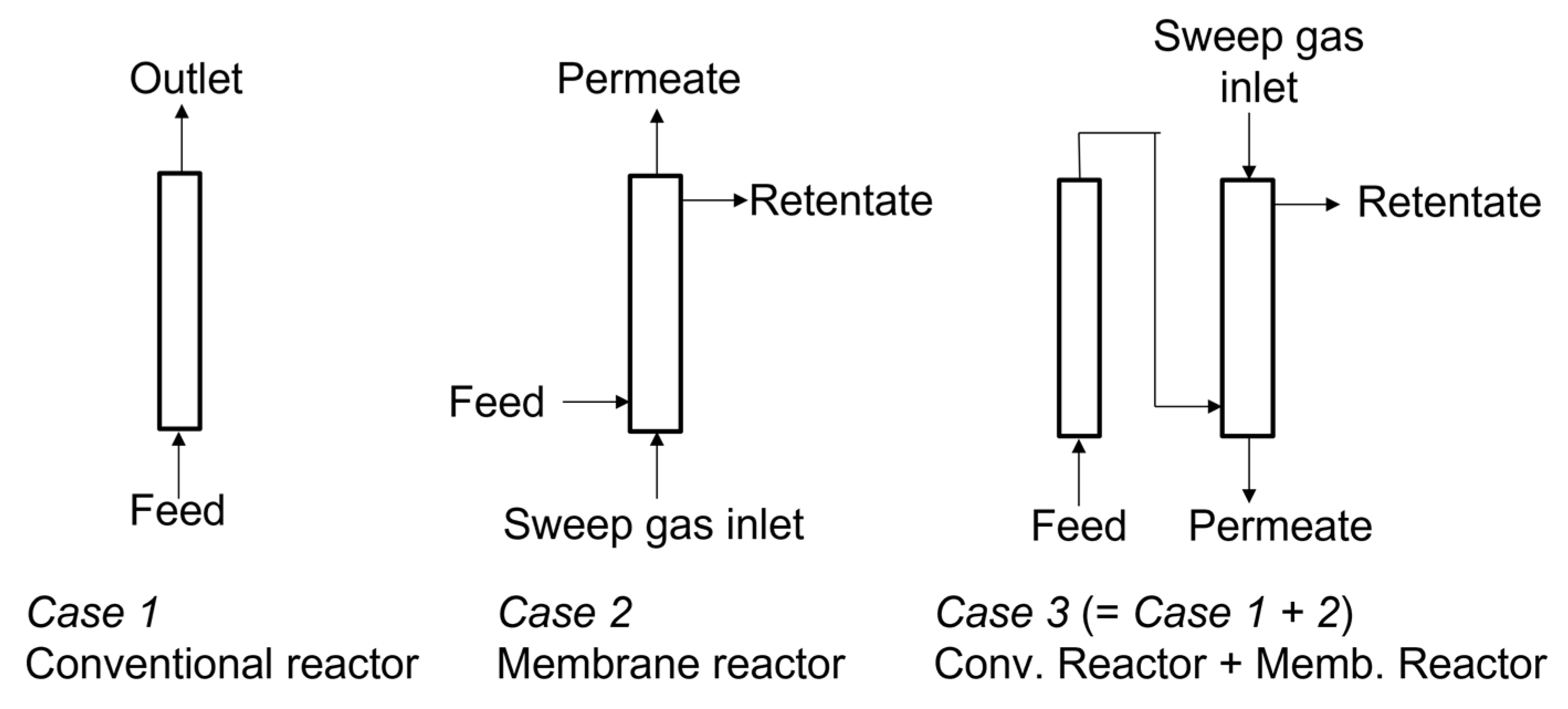
Figure 2.
Picture and schematic diagram of membrane reactor.
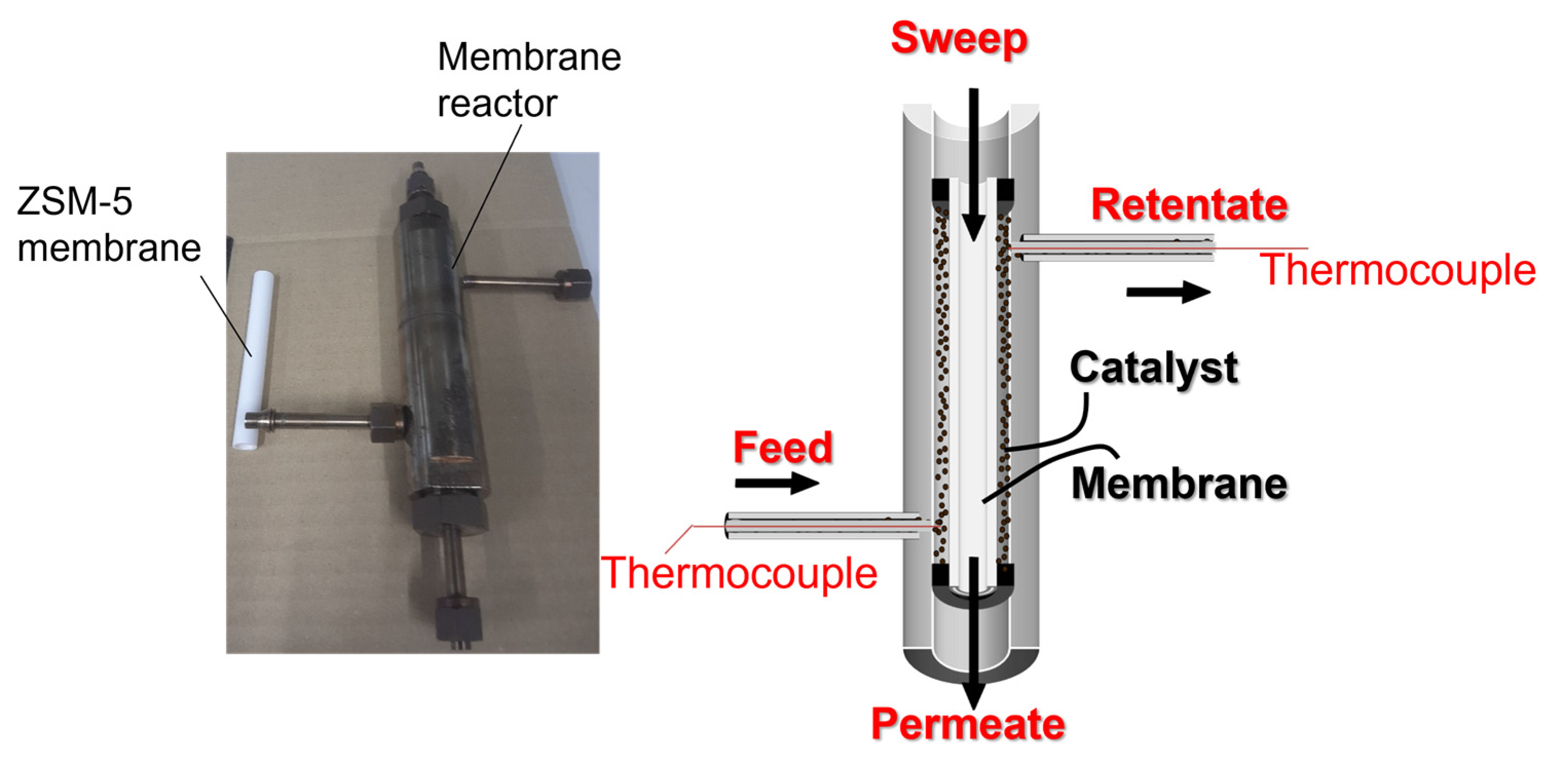
Figure 3.
(a) XRD patterns and (b) typical FE-SEM images of CuO/ZnO/γ-Al2O3 catalyst.
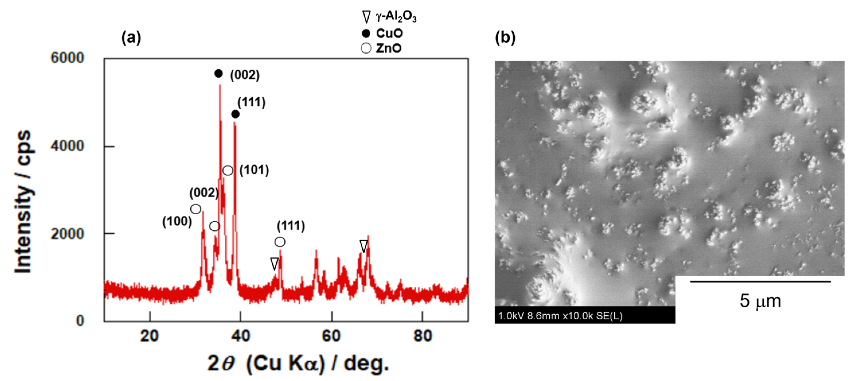
Figure 4.
XRD pattern of prepared membrane.
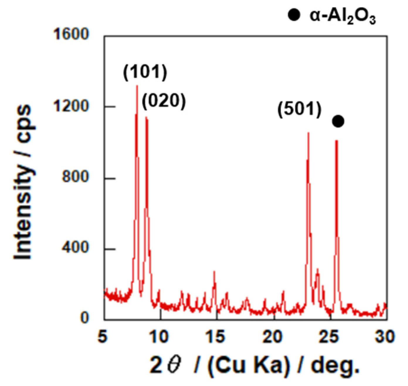
Figure 5.
Typical FE-SEM images of prepared membrane. (a) surface; (b) cross-section.

Figure 6.
Comparison of CO yields obtained in ◦, Case 1; ▵, Case 2 and □, Case 3. The dashed line shows the equilibrium yield.
Figure 6.
Comparison of CO yields obtained in ◦, Case 1; ▵, Case 2 and □, Case 3. The dashed line shows the equilibrium yield.
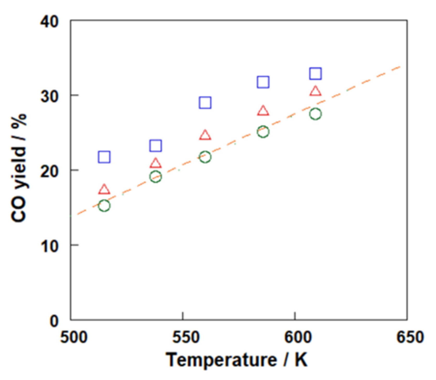
Figure 7.
Exit gas compositions of each reactor at 560 K. The bars from bottom to top showed H2, CO2, CO and H2O.
Figure 7.
Exit gas compositions of each reactor at 560 K. The bars from bottom to top showed H2, CO2, CO and H2O.


Table 1.
Results of separation tests for binary mixtures and single gas permeation tests.
| System | Temperature/K | Permeance/10−7 mol m−2 s−1 Pa−1 | Separation Factor/- | ||
|---|---|---|---|---|---|
| H2O | H2 | CO2 | |||
| H2O | 523 | 3.89 | - | - | |
| 623 | 3.58 | - | - | ||
| H2 | 523 | - | 1.73 | - | |
| 623 | - | 2.68 | - | ||
| CO2 | 523 | - | - | 1.31 | |
| 623 | - | - | 1.60 | ||
| H2O/H2 | 523 | 2.99 | 0.154 | - | 17.2 |
| 623 | 1.78 | 0.204 | - | 8.11 | |
| H2O/CO2 | 523 | 3.64 | - | 0.182 | 17.8 |
| 623 | 2.24 | - | 0.180 | 11.6 | |
Table 2.
Carbon balances in each reactor.
| Configuration | Carbon Balance/% | ||||
|---|---|---|---|---|---|
| 515 K | 538 K | 560 K | 586 K | 609 K | |
| Case 1 | 101.0 | 100.6 | 99.8 | 99.8 | 99.7 |
| Case 2 | 100.7 | 100.4 | 103.4 | 100.1 | 102.1 |
| Case 3 | 98.1 | 99.6 | 99.4 | 98.0 | 99.0 |
Publisher’s Note: MDPI stays neutral with regard to jurisdictional claims in published maps and institutional affiliations. |
© 2022 by the authors. Licensee MDPI, Basel, Switzerland. This article is an open access article distributed under the terms and conditions of the Creative Commons Attribution (CC BY) license (https://creativecommons.org/licenses/by/4.0/).
Share and Cite
MDPI and ACS Style
Sakai, M.; Tanaka, K.; Matsukata, M. An Experimental Study of a Zeolite Membrane Reactor for Reverse Water Gas Shift. Membranes 2022, 12, 1272. https://doi.org/10.3390/membranes12121272
AMA Style
Sakai M, Tanaka K, Matsukata M. An Experimental Study of a Zeolite Membrane Reactor for Reverse Water Gas Shift. Membranes. 2022; 12(12):1272. https://doi.org/10.3390/membranes12121272
Chicago/Turabian StyleSakai, Motomu, Kyoka Tanaka, and Masahiko Matsukata. 2022. "An Experimental Study of a Zeolite Membrane Reactor for Reverse Water Gas Shift" Membranes 12, no. 12: 1272. https://doi.org/10.3390/membranes12121272
Note that from the first issue of 2016, this journal uses article numbers instead of page numbers. See further details here.