Control Method for Signalized Intersection with Integrated Waiting Area


1
Business School, University of Shanghai for Science and Technology, Shanghai 200093, China
2
Hunan Provincial Key Laboratory of Intelligent Processing of Big Data on Transportation, School of Computer & Communication Engineering, Changsha University of Science & Technology, Changsha 410004, China
3
School of Information Science and Engineering, Fujian University of Technology, Fujian 350118, China
4
School of Information Engineering, Yangzhou University, Yangzhou 225127, China
*
Author to whom correspondence should be addressed.
Appl. Sci. 2019, 9(5), 968; https://doi.org/10.3390/app9050968
Submission received: 2 February 2019
/
Revised: 26 February 2019
/
Accepted: 4 March 2019
/
Published: 7 March 2019
(This article belongs to the Special Issue The Application of Sliding Mode Control in Robots)
Abstract
:Featured Application
Integrated waiting area can be used to increase the capacity of signalized intersections where land use is limited for the traffic movement without flaring up the approaches.
Abstract
To alleviate traffic congestion in the city, an integrated waiting area is introduced to the signalized intersection in this paper. After the design idea and the typical form of the integrated waiting area is proposed, the control method at the signalized intersection is discussed. The coordination control process of the main and pre-signal at the signalized intersection with the integrated waiting area is analyzed and modeled. To assess the operational performance of the integrated waiting area at intersections, a microscopic traffic simulation software (VISSIM) is utilized to simulate intersections with and without integrated waiting areas. Key issues concerning signal timing plans are then discussed. With comparisons between the operation of intersections with and without integrated waiting areas, the implementation effect is quantified based on the statistical data of the simulation result. The results confirm the potential benefits of the integrated waiting areas at the signalized intersections and show that integrated waiting areas work best in heavy traffic demand.

1. Introduction
Over the past few decades, there has been a rapid increase in the number of vehicles in developing countries such as China. As a result, frequent traffic jams have spread from large cities to small and medium-sized cities. Thus, this has become a focus problem that restricts the sustainable development of large and medium-sized cities in China. Intersections are the important nodes in the urban road network where many vehicles cross each other with a lot of conflicts. To make it worse, pedestrians and non-motorized vehicles are inevitably involved. This results in more complicated traffic conditions at the intersections. In addition, the intersections often become bottlenecks in road networks since the traffic capacity of the intersections is far less than that of the road sections. In particular, a single intersection with a low traffic capacity can cause a chain reaction. A congested intersection may substantially slow down the traffic, sabotaging the surrounding traffic system at the network level. Previous studies have indicated that delays at road intersections account for more than 80% of the total road network delays. At the same time, the intersection capacity is less than 50% of the road capacity. Increasing capacity and decreasing delay at signalized intersections have been areas of intense investigation. The optimization of lane assignment and signal control has been crucial for the intersection to improve capacity and decrease delay [1,2,3,4,5].
Many studies on the optimization of lane assignment have been conducted through the decades, including variable lanes, dynamic lane assignment and integrated waiting area. Jing Zhao, Wanjing Ma et al. [6,7] proposed a series of design pattern of left-turn waiting areas (LTWA) for different combinations of spatial and temporal treatments of left-turn movements and presented a generalized lane-based optimization model for the integrated design of displaced left-turn (DLT) intersection types, lane markings, the length of the displaced left-turn lane, and the signal timings. Hongmei Zhou, Jing Ding and Xiao Qin [8] developed a model that simultaneously optimizes the use of variable approach lane (VAL) and signal timings at an isolated signalized intersection and suggested that the availability of variable approach lane provided the intersection with improved capacity to deal with large traffic fluctuations. Jing Zhao, Jiao Yao et al. [9] evaluated the operational efficiency of the intersections with dynamic lane assignment using field data collected at five intersections in China. Jiang Jinsheng, Dong Ligeng [10] concluded that an integrated waiting area at the signalized intersection could effectively improve the traffic capacity of the approach and reduce stop time of vehicles through modeling and simulation. Guo Xiaofeng, Xiao Daiquan [11] studied the characteristic principle and setting condition of the integrated waiting area, and further analyzed the calculation method of the traffic capacity of the intersections with integrated waiting area. Shui Yanbin, Ye Pingyi [12] analyzed the application of integrated waiting area in the signalized control junction area at downstream ramp intersection of Chengdu second ring road. Ma Xiaodan, Ren Heng Kai, Xia Xiaomei [13] also analyzed the setting method and traffic control mode of integrated waiting area at the signalized intersection. Sun Jirui, Che Guopeng, Wen Hanhui et al. [14] studied the effect of integrated waiting area on the traffic capacity and delay of the intersection. Cai YanFeng, Liu ShuangYang, Sun Da-Zhi [15] put forward an optimization model of oversaturated queue overflow condition based on integrated waiting area, simulated the traffic running situation before and after optimization model was implemented in the target intersection.
There are also many pieces of research on signal control. The pre-signal control method was originally used for bus priority control to ensure that buses receive priority in the intersection, proposed by the British Transport Authority in 1991 [16]. Recently, pre-signal control methods for other vehicles have been studied in signalized intersections. Xuan Y.G., Daganzo C.F., Cassidy M.J. [17,18] proposed a pre-signal system that employs sorting strategies for generic intersections, illustrated the potential benefits of the proposed system, and demonstrated that the pre-signal control method can increase intersection capacity effectively by a natural experiment. Zhou Y.P., Zhuang H. [19] developed an optimization model of the lane assignment and signal timing at the tandem intersection with pre-signal to minimize the delay. Ma et al. [20,21] established a signal control model for an intersection entrance with a double-stop line. Li et al. [22] and Chen et al. [23] studied the method of setting the pre-signal at variable lanes of an intersection, with the aim of solving the problem of traffic jams and idle lanes caused by the uneven distribution of traffic flow.
As a special and complex traffic control mode, integrated waiting area (IWA) has been proposed recently as a solution to increase the capacity of the signalized intersection without flaring up the approaches. Although IWAs have been put into practice in several cities in China and decreased approach delays at some intersections in these cities which suffer from intersection space shortages, the application is still in its early stage, compared with other traffic management measures. An understanding of when and where the concept of IWA is desirable is important for its application. More studies are needed to optimize the traffic control method and quantitatively assess the impacts of IWA on the intersection capacity and travel times. To increase the utilization ratio of the approaches at signalized intersections, the pre-signal control is introduced into the integrated waiting area and a traffic control method combining the variable lanes and waiting areas is proposed in this paper.
2. Basic Concept of Integrated Waiting Area
2.1. Design Idea
The waiting area is the space where vehicles are waiting to go through the intersection. The effect of the existing left-turn and through movements waiting area at the intersection on easing the traffic pressure is limited. As well, the emergence of an integrated waiting area has added fresh blood to the design of the intersection.
An integrated waiting area is a novel kind of traffic control measure. It sets all approach lanes to be variable lanes and circularly switches the right of way of the traffic in different directions to fully utilize the time-space resources of the intersection in case the existing road supply is unchanged. With this kind of traffic control method, the traffic flow in different directions can be assigned on time and space at the approach of the intersection. With limited land in cities devoted to traffic, IWAs can be a method to increase the intersection capacity.
2.2. Typical Form
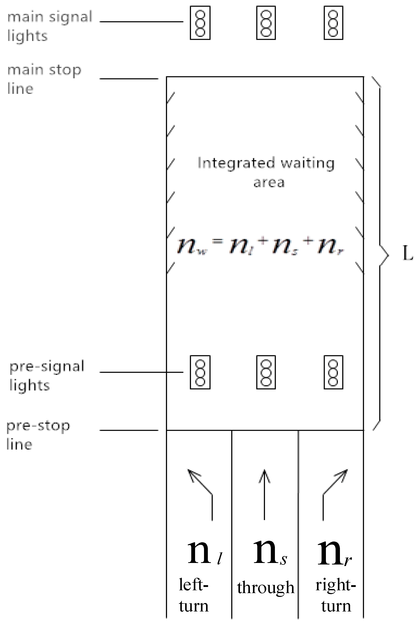
A typical layout of an integrated waiting area is shown in Figure 1. Since integrated waiting area is primarily aimed at the flow of motor vehicles, the influence of pedestrians and non-motorized vehicles is not considered in this paper [24,25].
There are two stop lines at the approach of the intersection with integrated waiting area. The original stop line is considered the main stop line. The pre-stop line is a solid or double dotted line parallel to the main line. It is set up at a certain distance upstream. Besides, a set of pre-signal lights are set up in the corresponding position in front of the pre-stop line with the aim of controlling the traffic of vehicles. The original left-turn, through and right-turn lanes move to the back of the pre-stop line. Then, the area between the main stop line and the pre-stop line will be designated as an integrated waiting area.
2.3. Organization of Traffic Flow at Intersection
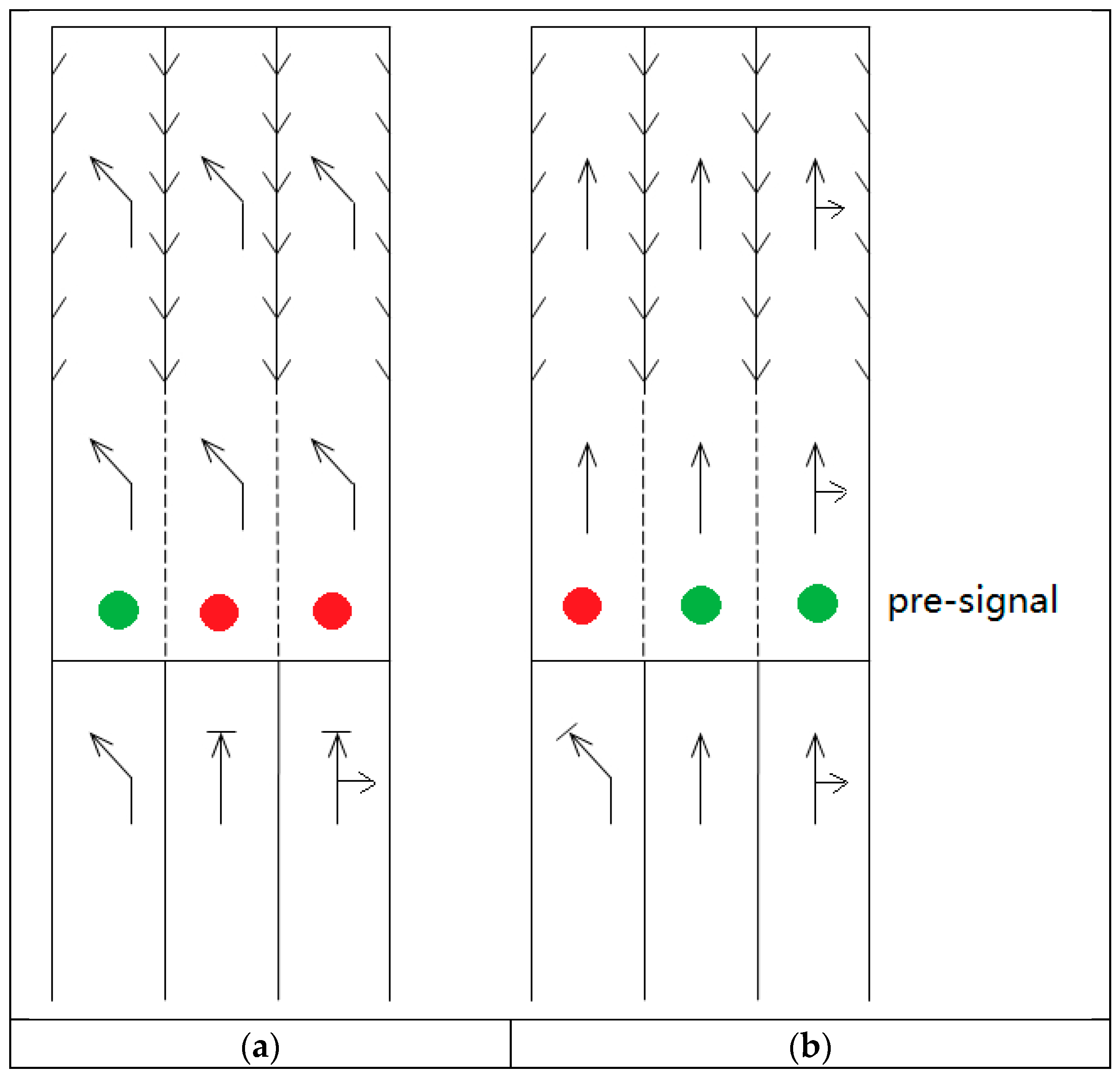
The basic design element of IWAs is the waiting area before the stop bar for left-turn, right-turn and through vehicles. The waiting area is for vehicles to utilize all the available lanes on the approach to clear the intersection, i.e., all available approach lanes can be used as through lanes, right-turn or left-turn lanes. The typical layout and traffic operation of the intersection with IWAs are shown in Figure 1 and Figure 2. Right turns are combined with the through traffic at the rightmost lane since the influence of right-turn vehicles at the intersection is usually small [6,7].
Figure 2a illustrates the phase for the left-turn movement. When the pre-signal provides a green indication for the left-turn movement, the vehicles on the left-turn lanes at the approach can cross the pre-stop line and distribute to all lanes in the waiting area until the main signal lights for the left-turn turn green. They then enter the intersection and leave. At the same time, through and right-turn vehicles are held upstream by the pre-signal for those lanes. Figure 2b illustrates the same rules for the through/right-turn vehicles.
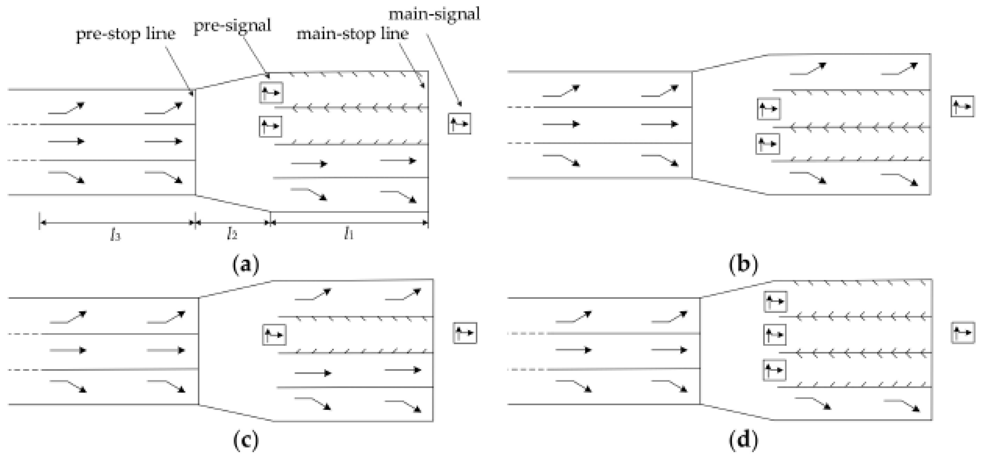
Using all approach lanes for the integrated waiting area, as illustrated in this case (Figure 1 and Figure 2), is ideal for fully utilizing intersection space. However, some considerations may prevent the use of all lanes for the integrated waiting area. For example, if right-turn traffic is relatively large in an intersection, the rightmost lane at the approach can be set as an exclusive right-turn lane with the right-turn special phase to control right turn traffic. Thus, leaving the right-turn flow out of the integrated waiting area, a ‘partial-IWA’ design can be adopted in such a situation, as shown in Figure 3d.
Figure 3 illustrates the layout of the partial-IWA. As shown in Figure 3a, two leftmost lanes are utilized as an integrated waiting area, while rightmost lane is an exclusive right-turn lane and next to the rightmost lane is a through lane. In Figure 3b, the leftmost lane is an exclusive left-turn lane and the rightmost lane is an exclusive right-turn lane. The two middle lanes are utilized as an integrated waiting area. Only one lane is utilized as an integrated area in Figure 3c.
For example, in the design shown in Figure 3a, right-turn vehicles can utilize the rightmost lane without waiting for pre-signal indication. The same rule applies for the through movement vehicles to use the second lane on the right. The pre-signal will control the timing for left-turn/through vehicles to enter the two leftmost lanes, i.e., IWA. Though these designs in Figure 3 cannot fully engage all the approach lanes, they do provide solutions where the available lanes downstream of the intersection are limited or space does not allow several simultaneous turning movements.
With the periodic changes of the main and pre-signal lights at the approach, the function of all lanes in the integrated waiting area can be switched between left-turn and through movement [26]. More particularly, the traffic in the integrated waiting area has undergone the process of “entering—waiting—proceeding—clearing”.
To make full use of the integrated waiting area at the signalized intersection, it is necessary to discuss and optimize a control method based on the general form of the integrated waiting area proposed above.
3. Signal Control Method
3.1. Signal Phase Sequence
Since integrated waiting areas aim to ease congestion at intersections where traffic demand is high, adaptive control does not have many advantages over fixed-time controls [27].
As shown in Figure 1, two stop lines are installed on the intersection approach with the first one located at the front of the integrated waiting area and the second stop line downstream at the end of the integrated waiting area. The control method of the signalized intersection with integrated waiting area is different from the conventional intersection without integrated waiting area. An intersection with integrated waiting area can be operated by two pre-timed signal controllers: one for the pre-signals on the approach with integrated waiting area and the other for the main intersection. A set of pre-signal lights group is added at the pre-stop line of the waiting area. In addition, all the traffic flow from each direction is controlled by the pre-signal lights to enter the waiting area safely and orderly [28].
The signal timing plan can be divided into two sub-plans, which are integrated. One is the plan for the main intersection signals, and the other is for the pre-signals. These two signal timing plans share an identical cycle length, so an intersection with integrated waiting areas can be operated continuously.
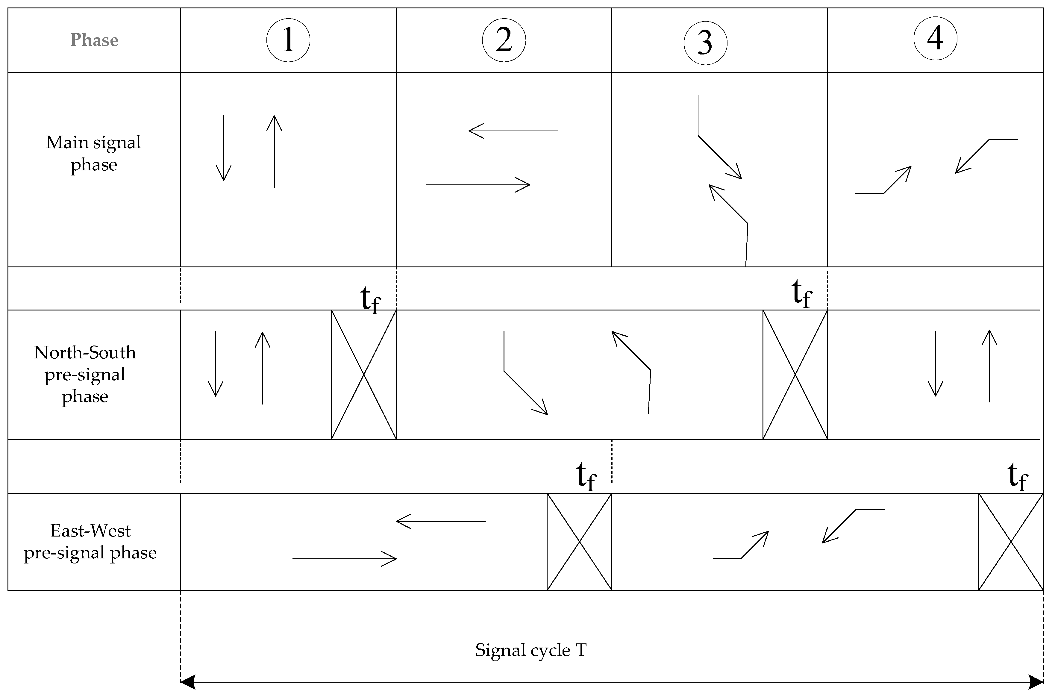
Two phases are employed for pre-signals with the first phase for through vehicles and the second for left-turn vehicles. The signal timing strategies for the main intersection is also illustrated in Figure 4. Left-turn indication for approaches follows a through indication. During the first phase, the upstream pre-signals provide a green indication for the through movement at NS and EW approaches. Through movement vehicles proceed downstream distributing to all available lanes in the integrated waiting areas. Meanwhile, right-turn vehicles proceed to the rightmost lane in the integrated waiting areas as shown in Figure 2b. Then the right-turn vehicles will pass through the intersection under the give-way rules. The reason for providing a green indication for the EW through movement when the main signal provides the green indication for the NS through movement is to leave more time for vehicles to enter the integrated waiting areas. The downstream signal at the main intersection, afterwards, provides a green indication for the through movement of all available lanes at the WB and EB approaches. During this phase, left-turn vehicles are held upstream by the pre-signal for those lanes. Phase 2 for pre-signal is for left-turn movements. Through movement vehicles are held at the pre-signal while left-turn vehicles distribute to all available lanes and right-turn vehicles proceed to the rightmost lane in the integrated areas at the WB and EB approaches, where the left-turn vehicles receive a circular green indication at the downstream signal to pass through the intersection and right-turn vehicles pass through the intersection under the give-way rules. Each phase requires an all-red time that is long enough to clear the integrated waiting areas.
Accordingly, it is important to understand how to coordinate between the pre-signal and main signal at the intersection. The main and pre-signal coordinated control method should be adopted for the intersection with integrated waiting areas. Figure 4 displays the phase and sequence of the signal at a typical cross intersection with integrated waiting areas.
Residual vehicles in the integrated waiting areas pose potential safety concerns. If there is a through movement vehicle left in the integrated waiting area when the through movement indication for this approach ends, it will be hard for this vehicle to pass through the intersection when the left-turn indication begins. This vehicle must stop, wait for the next indication for through movement in the next cycle and therefore block the entire lane for the duration of the cycle, during which the lane of the integrated waiting area cannot serve other vehicles behind this vehicle which is left. A similar situation will happen for a left-turn vehicle if this vehicle cannot leave the integrated waiting area and pass through the intersection in time. To avoid residual vehicles, it is crucial to have lane-clearing time. This can be regarded as the red indication of the pre-signal, meaning the green indication of the pre-signal should end earlier than the corresponding indication of the main intersection signal. The pre-signal will hold vehicles and enable those vehicles that have entered the integrated waiting areas to pass through the intersection. For example, the pre-signal indication for a through movement shall end earlier than the through movement indication in the main signal of the intersection to prevent residual vehicles in the integrated waiting areas. It means that the difference () of the end time of the green signal phase between pre-signal and main signal must be satisfied:
where l is the length of the integrated waiting area (m); is the average speed of the vehicles passing through the integrated waiting area (m/s).
3.2. Coordination of Main and Pre-Signal Control
3.2.1. Process of Coordination Control
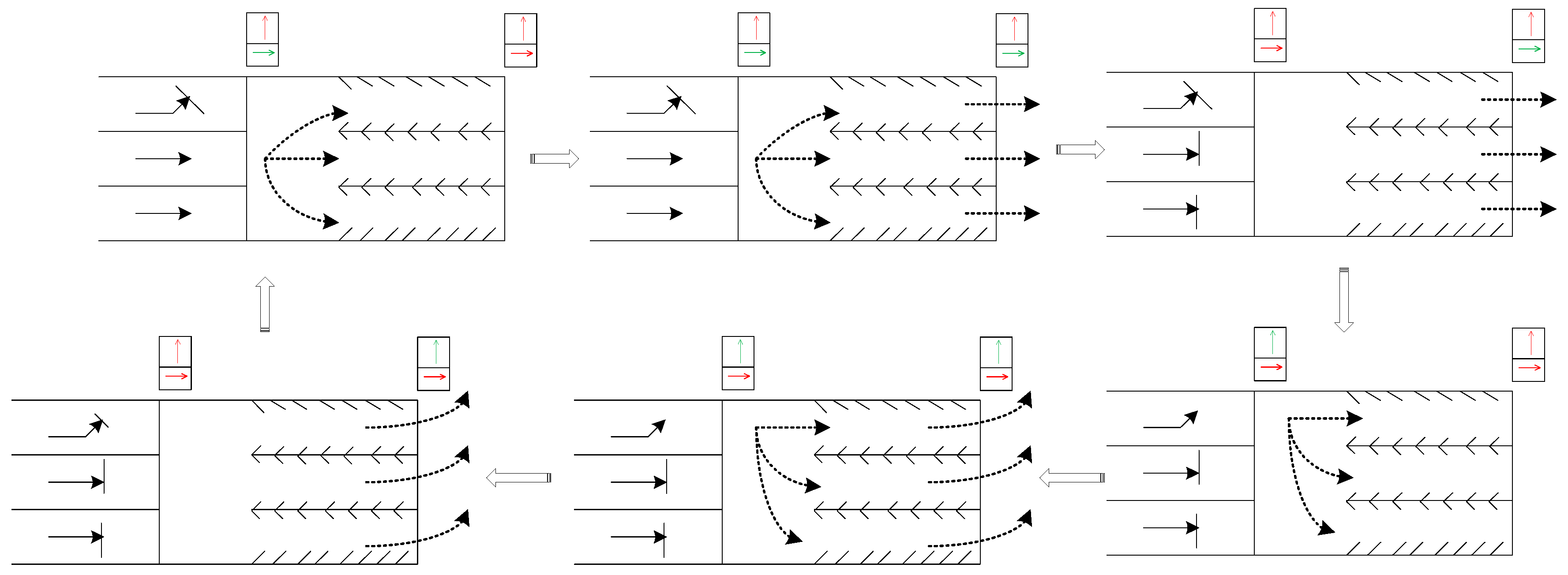
According to the proposed control method, the basic idea of the coordinated control of main and pre-signal in the integrated waiting area is shown in Figure 5. The arrived right-turn vehicles are not controlled by the pre-signal. Right-turn vehicles pass through the intersection according to the give way rules. The pre-signal is used to control the direction of the available lanes in the integrated waiting area. The available lanes serve through and left-turn traffic alternately in a signal cycle. Right-turn vehicles will use the rightmost lane in the integrated waiting area as shown in Figure 2.
The rules of pre-signal control are as follows:
- The arrived right-turn vehicles are not controlled by the pre-signal. They will use the rightmost lane in the integrated waiting area.
- The arrived through and left-turn vehicles should stop at the pre-stop line to wait for the corresponding green light of the pre-signal.
When pre-signals at the approach provide a green indication for the through movement, all the through vehicles stopped at the pre-stop line are permitted to enter the integrated waiting area and distributed in all the available lanes in the integrated waiting area. The arrived left-turn vehicles should stop and wait in line at the pre-stop line. Vehicles that distributed in the integrated waiting area stop while the main signals provide a red indication for the through movement. When the main signal light of this phase turns green, all the vehicles waiting in the integrated area will start to pass through the main stop line into the intersection. Meanwhile, the other through movement vehicles that have not yet entered the waiting area may also go through the waiting area directly. Therefore, vehicles going through the intersection are cleared gradually. At the same time, the left-turn vehicles arriving will stop and wait at the pre-stop line. After some time, the pre-signal lights for through movement will turn red. Thus, the through movement vehicles will have to stop entering the waiting area. After the vehicles distributed in the integrated waiting area are cleared, the main signal light for the through movement turns red. Then the left-turn phase of the pre-signal turns green.
Similarly, the left-turn vehicles waiting at the pre-stop line will start to enter the integrated waiting area and distribute in the available lanes. All the lanes in the integrated waiting area will be utilized for the left-turn vehicles. The through movement vehicles arriving should stop and wait in line at the pre-stop line. All the left-turn vehicles are waiting in the integrated area while main signal lights for the left-turn movement keep red. When the main signal lights for left-turn turn green, all the vehicles waiting in the integrated area will start to pass through the main-stop line into the intersection. Meanwhile, the other left-turn vehicles that have not yet entered the waiting area may also pass directly through the waiting area. Thus, left-turn vehicles will also be cleared gradually. After some time, the pre-signal lights for left-turn vehicles will turn red. Thus, the left-turn vehicles will have to stop entering the waiting area. When all the left-turn vehicles distributed in the integrated waiting area are cleared off, the main signal light for left-turn vehicles turns red. The operation of the integrated waiting area will switch to the through phase and follow this cycle back and forth.
More importantly, clearance of the vehicles in the waiting area is critical, as it directly affects the normal traffic of the other directions in the waiting area afterwards. Therefore, the following regulations are proposed in the paper:
All vehicles that have passed through the pre-stop line must enter the intersection and pass through the main stop line in sequence within the corresponding clearing time. Vehicles should be prohibited from staying in the waiting area beyond the waiting and clearing time of this direction. Where it is impossible for the vehicles to leave the waiting area in time due to unavoidable cases like vehicle flameout or other special reasons, it is necessary to change direction in accordance with the vehicles’ direction during the next phase in the waiting area to ensure that the operation of the traffic in the integrated waiting area and intersection does not become abnormal.
Basing on this analysis, it is evident that the timing parameters of the main-signal and pre-signal are the most important factors ensuring the smooth operation of the variable lanes in the integrated waiting area of the signalized intersection.
3.2.2. Model of Coordination Control
(1) Objective function
To satisfy the constraints of the saturation of approaches at the intersection, it is notable that the shorter the phase time for the through movement and the left-turn is, the shorter the cycle time will be. As well, the operation efficiency of the intersection can be improved highly when the number of the right-turn vehicles are relatively small.
Other than the ending time difference between the main-signal and pre-signal green phase in the integrated waiting area discussed in Section 3.1, the starting time of the pre-signal must be earlier for a phase equal to the releasing time of the cross-direction traffic than that of the main signal. To meet the requirement of traffic in the cross-direction, this phase time is employed as the starting time difference between the main-signal and pre-signal phase in the waiting area [29]. Usually, the smaller is, the smaller the queuing time for the vehicles waiting to enter the waiting area will be. This will also ensure a higher operation efficiency of the waiting area as well as shortening the cycle time.
Based on the above analysis, the objective function of the coordinated control model of the main and pre-signal in the waiting area is expressed as:
where: is the duration of green time for through movement at the main signal (s); is the green time of the main signal for left-turn vehicles(s); is the difference of the start time for the through movement between main and pre-signal phase (s); is the difference of the start time for the left-turn movement between main and pre-signal phase (s).
(2) Constraints
For the convenience of expression, Table 1 explains the related variables. The convention is as follows: The variable subscript T represents the through movement, while the variable subscript L denotes the left-turn movement.
To coordinate the control of the main and pre-signal in the integrated waiting area, except for the starting and ending time of the green light between the main and pre-signal, both signal cycles should be the same. They are all constrained by the length of the total cycle of the intersection, and expressed as follows:
To ensure that all the waiting vehicles pass through the waiting area during the phase of the release, a clearance time should be met as expressed in Formula (9):
The saturation requirements of the traffic flow from all directions should be satisfied under the control plan of the main and pre-signals. The saturation degree before the pre-signal in the integrated waiting area should not be greater than the maximum saturation the road can carry.
For the through and left-turn traffic, the capacity of the main signal should be the same or greater than the capacity of the pre-signal, constraints are as follows:
According to the signal timing rule of the conventional intersection, duration of green for through and left-turn movement should be constrained as the maximum value and minimum value.
If the length of the integrated waiting area is larger than the maximum queuing length of vehicles in the waiting area, it will cause a waste of resources. In contrast, if the length of the integrated waiting area is smaller than the minimum queue length of vehicles in the waiting area, vehicles will possibly queue up after the pre-signal, thus the resources in the waiting area will not be fully utilized [30]. As such, it is idealistic that the length of the integrated waiting area is between the maximum and minimum of queue length.
(3) Control model
A multi-objective linear programming problem is considered. The objectives can be divided into two levels.
Level 1: minimizing the total phase times of the through movement and the left-turn.
Level 2: minimizing the starting time difference between the main signal and pre-signal of the two movements with the same weight . Then, the optimization model turns to be a linear programming problem with the objective of Equation (19), and constraints (3)–(18), which can be solved by the commercial optimizer Lingo.
M is an arbitrarily large positive constant number.
4. Simulation and Practical Application
Traffic flow at the signalized intersections is time-varying and random. It is also often difficult to use empirical models or mathematical models to accurately describe the characteristics of the traffic flow. In this Section, the microscopic traffic simulation software, PTV VISSIM 9.0 (2016, PTV, Karlsruhe, German) is utilized in studying the typical form of the integrated waiting area and the practical application. It is a microscopic and time-based traffic simulation program. It is employed in this research because of its ability to model unconventional lane uses and signal timing plans. The correlation evaluation indicators with or without integrated waiting area are compared and analyzed to evaluate the effect of the integrated waiting area setting at the signalized intersection.
4.1. Basic Ideas of Microscopic Traffic Simulation
The microscopic traffic simulation system is a complex and random dynamic system. The realization of the simulation system is a cyclic process. It includes problem analysis, data acquisition, model establishment, parameter selection, simulation operation, and result analysis [31,32].
Problem analysis is the overall analysis, description and characterization of traffic problems. The basic data required for microscopic traffic simulation modeling include the following: road geometry data (such as number of lanes, lane width, barrier width, non-motor vehicle lane width, lane division, and road intersection form), traffic flow characteristic data (such as traffic volumes, traffic composition, ratio of turning vehicles, vehicle arrival distribution, vehicle speed distribution, vehicle queuing and dissipation), traffic control data (such as signal timing of each intersection and traffic management), which depend on the research objectives [33,34,35].
To obtain the best simulation results, simulation parameters are selected according to sites, traffic status as well as evaluation targets in the microscopic traffic simulation system. The parameters of the simulation are continuously adjusted to ensure the accuracy of the microscopic model [36].
The operation of different random seeds can be regarded as different observations of the system. To ensure the reliability of the simulation output, multiple random seeds are utilized for multiple simulations. The results of the simulation are recorded generally after the system is stable. The average value of each operation result is also used as the final result. In regard to the statistics and analysis of the simulation results, multiple schemes can be compared.
4.2. Simulation of Typical Form Intersection
The simulation is conducted on the intersection with integrated waiting area shown in Figure 2. The road segment and intersection model with and without integrated waiting area are respectively established in VISSIM in different scenarios. After that, the corresponding signal control parameters are introduced. One is with integrated waiting areas and the other is without integrated waiting areas. The similar geometric elements are used for intersections with and without integrated waiting areas. The results from the two intersections will be compared so that an overall understanding of the advantages and limitations of integrated waiting areas will be gained.
The main and pre-signal timing schemes are shown in Table 2 and Table 3. Length of the area is set as 70 m, and the average speed in the VISSIM platform for this study is 40 km/h. According to the length of the waiting area and the average speed of the vehicle in the experimental model, the clearing time of the waiting area is considered as 6 s.
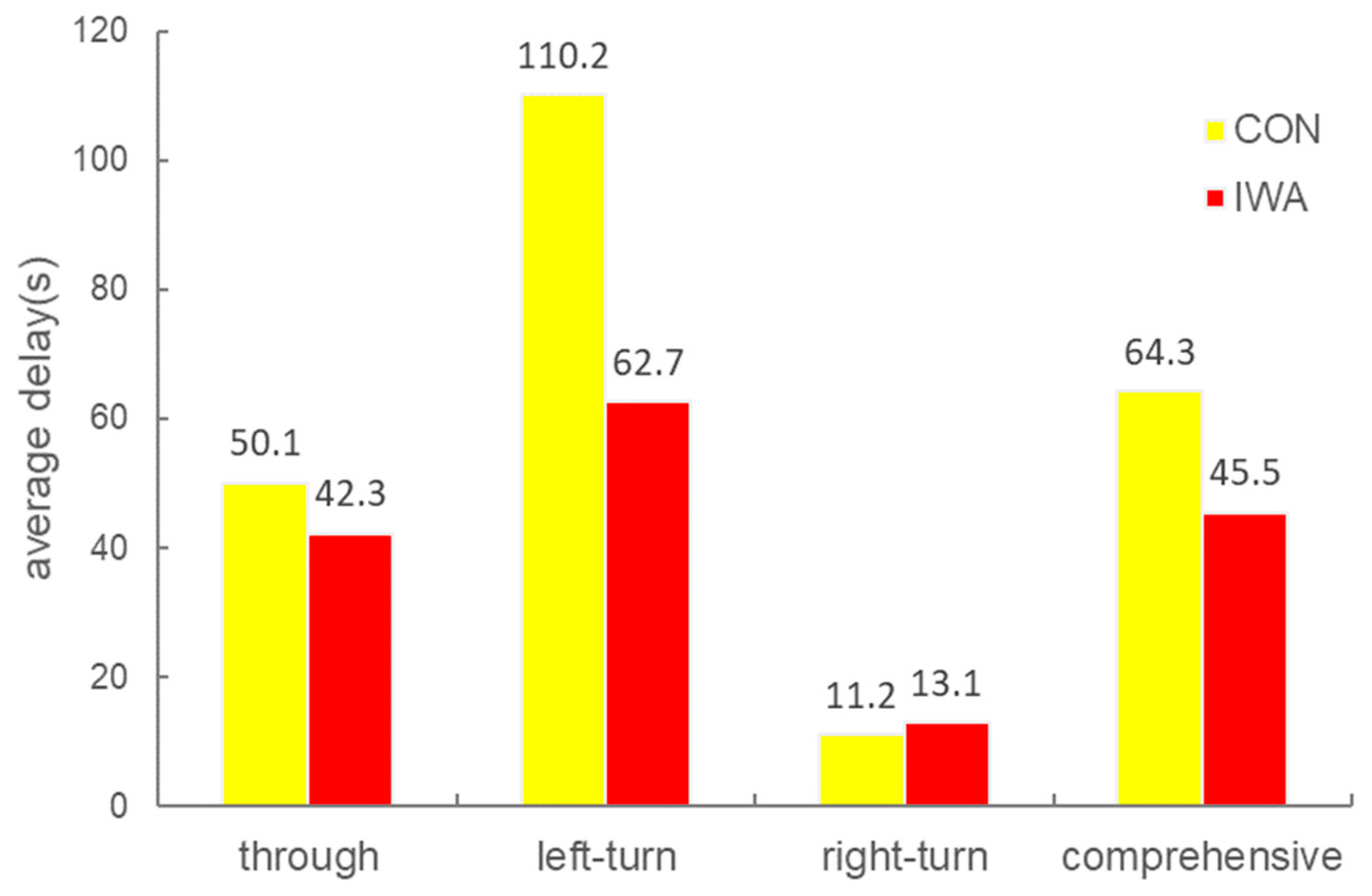
The input of the flow rate of the through, left-turn and right-turn vehicles in the peak hour is 1200 pcu/h, 600 pcu/h and 200 pcu/h respectively. To evaluate the simulation results, the average vehicle delays for an hour with and without the integrated waiting area are calculated and compared as illustrated in Figure 6.
From the figure, it is observable that the average vehicle delay for left-turn and through movement at a signalized intersection with the integrated waiting area is lower than that without it. However, right-turn vehicles’ delay is a little higher. During the simulation, right-turn vehicles only use the rightmost lane in the integrated waiting area and pass through the intersection with the give-way rules. So right-turn vehicles may be delayed by the through vehicles or left-turn vehicles stopping in the front of them. The results indicate that for the general form of the integrated waiting area studied in this paper, the average delay of left-turn vehicles with the integrated waiting area is decreased by about 43%. In addition, the efficiency of the approach in the intersection is increased.
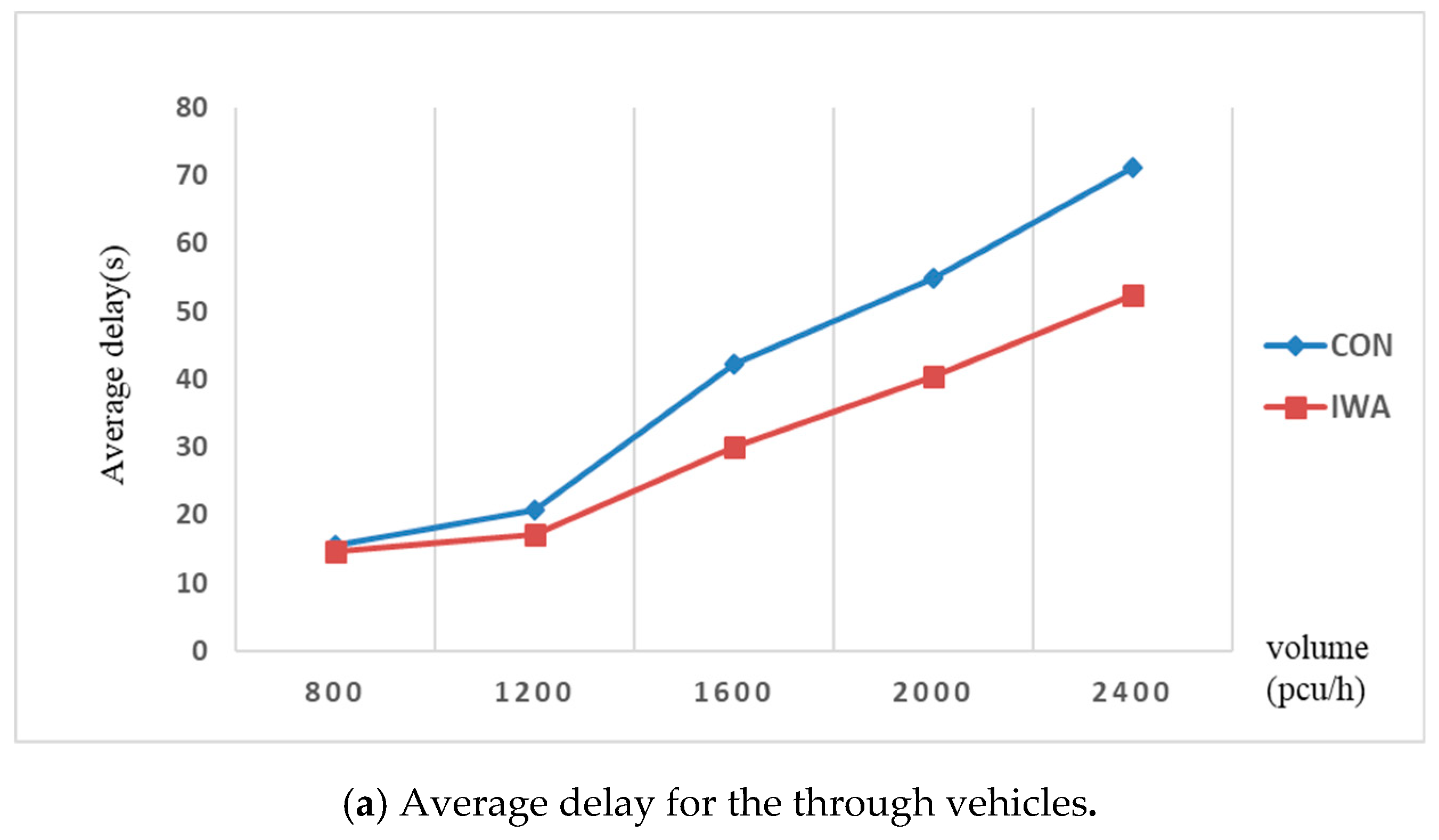
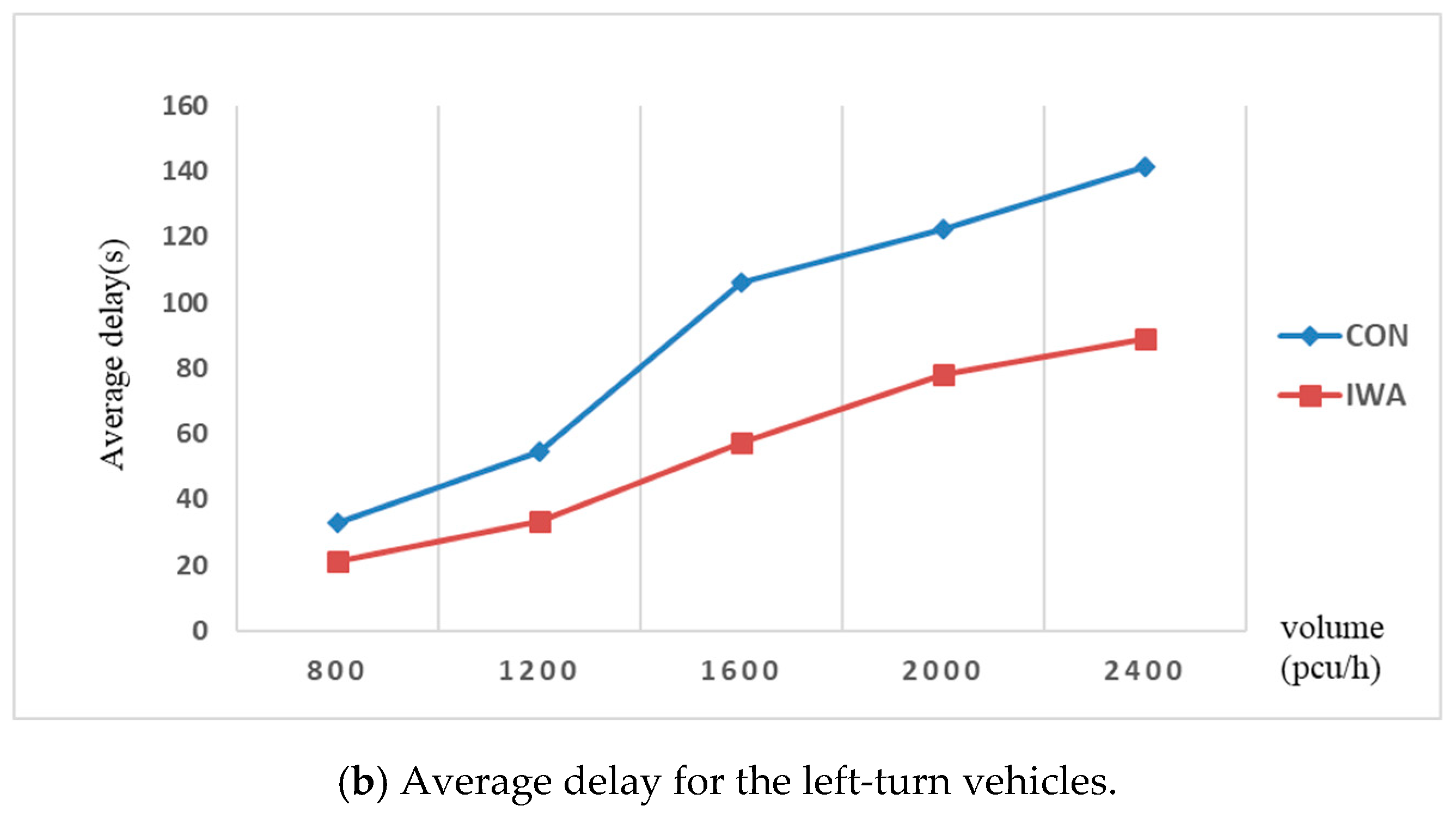
To evaluate the effect of the design of the integrated waiting areas on the movements at the signalized intersections under different conditions, the volume for the approach is changed. The average vehicle delays for an hour with and without the integrated waiting area under different volumes are calculated and compared as illustrated in Figure 7.
4.3. Practical Application
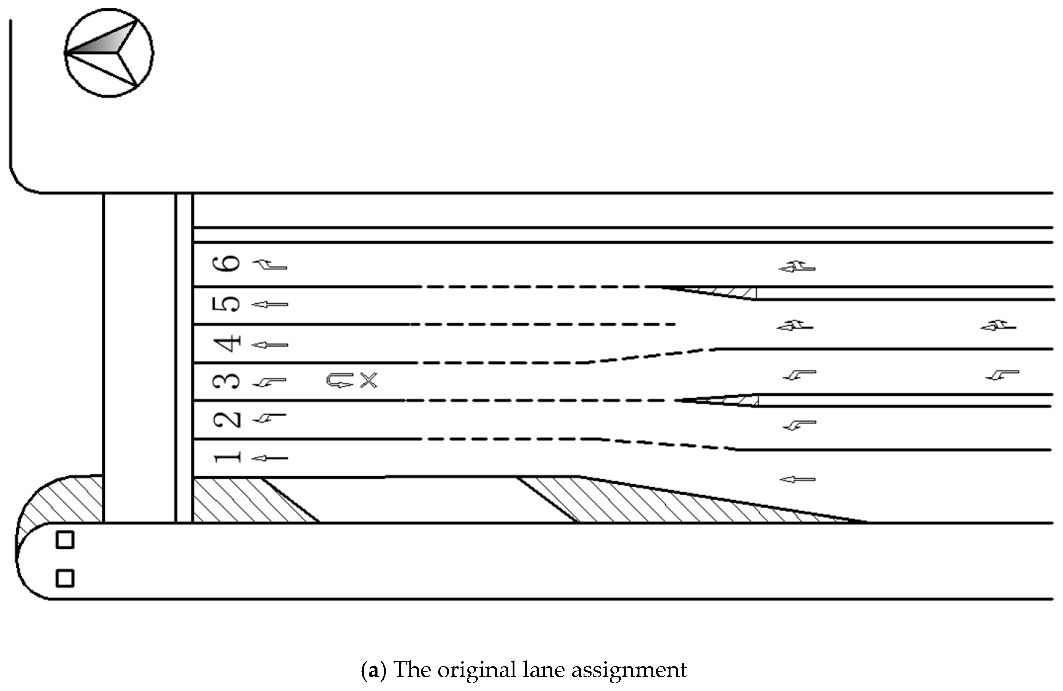
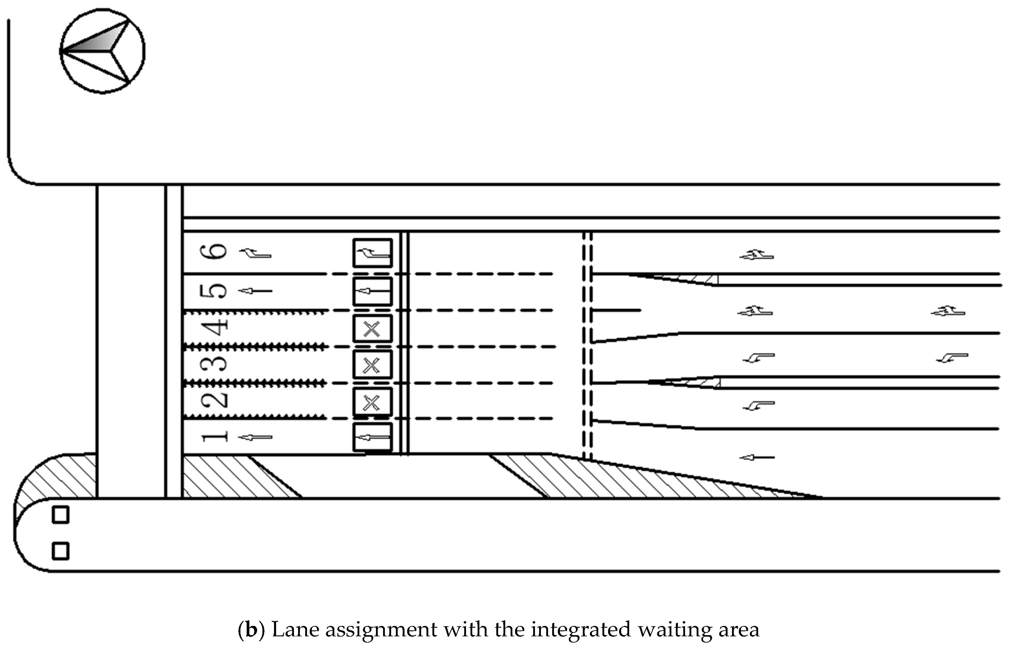
The intersection of Linyi Road and Gonghe New Road in Zhabei District of Shanghai city is taken as an example to illustrate the practical application of the integrated waiting area. There are six lanes in the south entrance of this intersection. Lanes 1, 4 and 5 are used for the through vehicles, while lanes 2 and 3 are used for the left-turn vehicles. Lane 6 is used for right-turning vehicles.
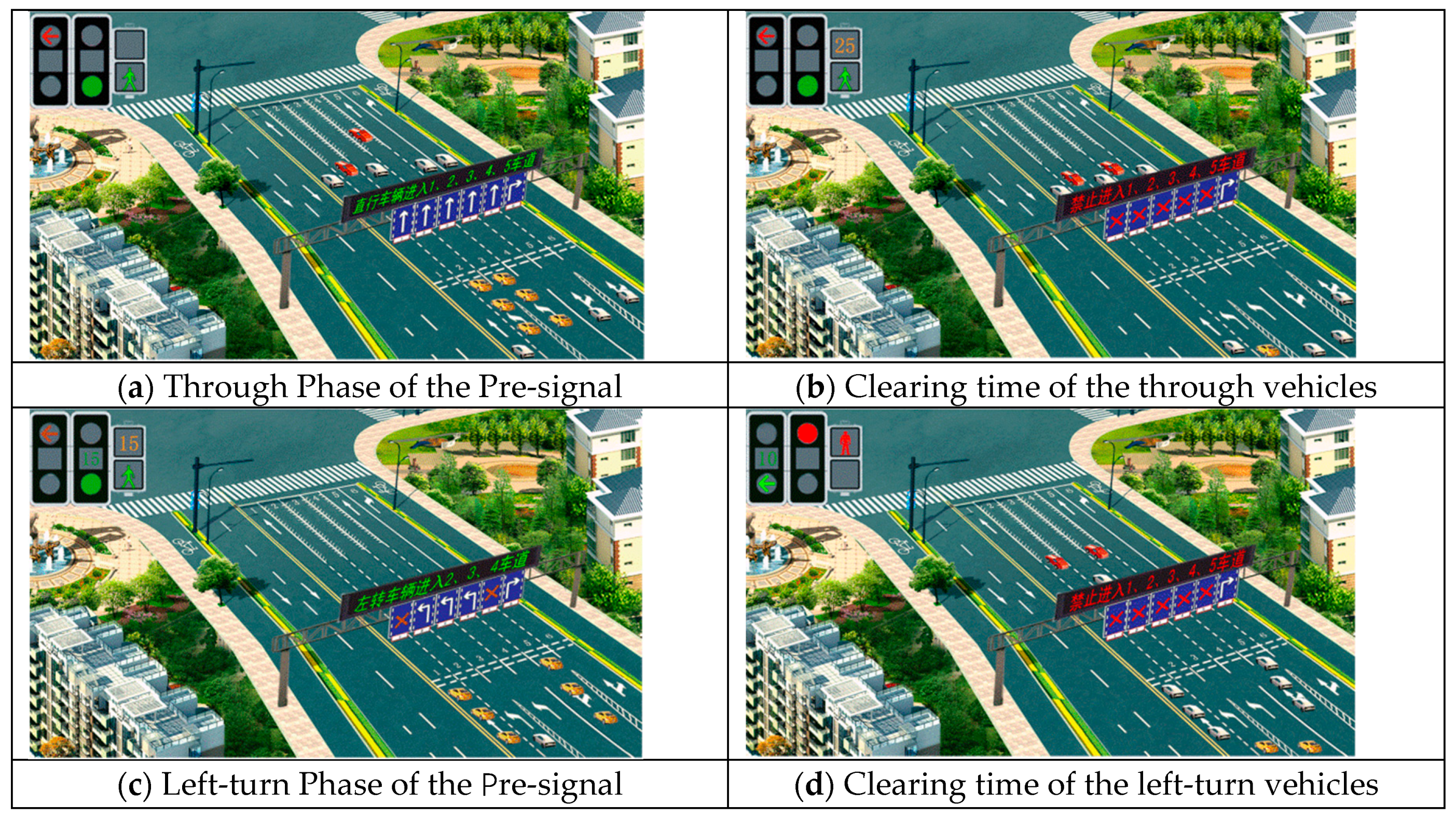
By adding a set of LED variable signs, some lanes are turned into “variable waiting lanes”. As regards the control plan, it is possible to switch the “integrated waiting area” between through vehicles and the left-turning vehicles waiting lane. After the implementation of the integrated waiting area, lanes 2 to 4 at the south approach of the intersection are set as the three variable waiting lanes (see Figure 8b). Figure 9 illustrates the signal phase sequence with the integrated waiting area. Arriving vehicles can enter the integrated waiting area according to the prompt information indicated by the LED variable sign, and then pass through the intersection according to the phase of the main signal.
By modifying the number of random seeds in the simulation menu, five simulation experiments were performed with or without the integrated waiting area, and the random seed number was taken as 42, 369, 1578, 5961, and 7171 respectively. Table 4 and Table 5 depict the experimental data and results. It is observable that the design of the integrated waiting area at the signalized intersection reduces the travel time and delay spent by the vehicle passing through the intersection. It also improves the efficiency of the intersection. In particular, the improvement of the left-turning vehicle lane is apparent. In addition, the average travel time and vehicle delay decrease by about 18 s, while the improvement range is 24.9% and 31.3% respectively. Meanwhile, it is also apparent that the average travel time and delay of the through vehicles have not decreased as much as that of the left-turn vehicles.
5. Conclusions
The integrated waiting area can be a cost-effective solution when an intersection faces high demand but limited land use. The basic idea of the integrated waiting area is to use part of approach lanes as left-turn and through waiting areas to fully utilize space resources at a signalized intersection. According to the number of lanes available used as the waiting area at the approach, two different design of integrated waiting area are mentioned: full-IWA and partial-IWA. Theoretically, the design of full-IWA should generate greater benefits than a partial-IWA design. An evaluation of full-IWA performance and partial-IWA performance are considered and evaluated with the microsimulation system VISSIM. The experiment calculation results showed that the design of full-IWA exceeds the conventional intersection design in terms of decreasing the vehicle delay at the case study intersection. Furthermore, traffic volumes were changed. The delay analysis results show that, as the traffic volume increases, the effect of the design on decreasing the intersection delay will be even greater. It verified that the proposed full-IWA and partial-IWA design can effectively reduce vehicle delay and improve the traffic efficiency of oversaturated intersections. Evaluation of other partial-IWA performance should be considered in future research.
Author Contributions
X.X. and X.M. conceived and designed the experiments; X.M. performed the experiments; X.X. and X.M. analyzed the data; J.W. contributed materials and analysis tools; X.X. wrote the paper.
Funding
This work is supported by the National Natural Science Foundation of China (61772454, 61811530332, and 61811540410).
Conflicts of Interest
The authors declare no conflicts of interest.
References
- Zhao, J.; Ma, W.; Xu, H. Increasing the Capacity of the Intersection Downstream of the Freeway Off-ramp Using Presignals. Comput.-Aided Civ. Infrastruct. Eng. 2017, 32, 674–690. [Google Scholar] [CrossRef]
- Zhao, J.; Liu, Y.; Wang, T. Increasing Signalized Intersection Capacity with Unconventional Use of Special Width Approach Lanes. Comput.-Aided Civ. Infrastruct. Eng. 2016, 31, 794–810. [Google Scholar] [CrossRef]
- Li, L.L.; Qu, Z.W.; Song, M.M.; Wang, D.H. Control Strategy of Variable Lane. J. Jilin Univ. (Eng. Technol. Ed.) 2009, 39, 98–103. [Google Scholar]
- Li, L.L.; Qu, Z.W.; Chen, Y.H.; Wang, D.H. Research on Variable Lane Signalized Control Method. In Proceedings of the 2009 International Conference on Measuring Technology and Mechatronics Automation, Zhangjiajie, China, 11–12 April 2009; pp. 575–578. [Google Scholar]
- Cheng, C.; Qian, G.; Sun, Q. Study on the application method of variable-direction lane at signalized intersection. Urban Roadway Flood Control. 2013, 4, 37–40. [Google Scholar]
- Ma, W.; Liu, Y.; Zhao, J.; Wu, N. Increasing the Capacity of Signalized Intersections with Left-turn Waiting Areas. Transp. Res. Part A Policy Pract. 2017, 105, 181–196. [Google Scholar] [CrossRef]
- Zhao, J.; Ma, W.; Head, K.L.; Yang, X. Optimal Operation of Displaced Left-turn Intersections: A Lane-based Approach. Transp. Res. Part C-Emerg. Technol. 2015, 61, 29–48. [Google Scholar] [CrossRef]
- Zhou, H.; Ding, J.; Qin, X. Optimization of Variable Approach Lane Use at Isolated Signalized Intersections. Transp. Res. Rec. 2016, 2556, 65–74. [Google Scholar] [CrossRef]
- Zhao, J.; Yao, J.; He, S.; Han, Y. Operational Efficiency Evaluation of Intersections with Dynamic Lane Assignment Using Field Data. J. Adv. Transp. 2017, 2017, 2130385. [Google Scholar] [CrossRef]
- Jiang, J.S.; Dong, L.G. Modeling and Simulation of Versatile Waiting-Area at Isolated Signalized Intersection. J. Shanghai Univ. (Nat. Sci.) 2012, 18, 606–616. [Google Scholar]
- Guo, X.F.; Xiao, D.Q. Urban Intersection Traffic Improvement Methods in Comprehensive Waiting Area. J. Transp. Inf. Saf. 2013, 31, 68–73. [Google Scholar]
- Shui, Y.P.; Ye, P.Y. Application of the Comprehensive Vehicle-waiting Area in Signal Control for Junction Area at Down Ramp Intersection of Chengdu Second Ring Road. Surv. Des. 2014, 32, 107–113. [Google Scholar]
- Ma, X.D.; Ren, H.R.; Xia, X.M. Study on the Setting of Integrated Waiting Area at Signalized Intersection. For. Eng. 2015, 31, 118–122. [Google Scholar]
- Sun, J.R.; Che, G.G.; Wen, H.H.; Shan, S. Research on Influences of Comprehensive Stay Line Area on Passing Capacity and Delay at Intersections. Technol. Highw. Transp. 2015, 1, 121–125. [Google Scholar]
- Cai, Y.-F.; Liu, S.-Y.; Sun, D.-Z. Research on Optimization Model of Oversaturated Queue Overflow Condition Based on Integrated Waiting Area. J. Resid. Sci. Technol. 2016, 13, 265.1–265.8. [Google Scholar]
- Wu, J.; Hounsell, N. Bus Priority Using Pre-signals. Transp. Res. Part A Policy Pract. 1998, 32, 563–583. [Google Scholar] [CrossRef]
- Xuan, Y.G.; Daganzo, C.F.; Cassidy, M.J. Increasing the Capacity of Signalized Intersections with Separate Left turn Phases. Transp. Res. Part B 2011, 45, 769–781. [Google Scholar] [CrossRef]
- Xuan, Y.G.; Cassidy, M.J.; Daganzo, C.F. Using a Pre-signal to Increase Bus and Car-carrying Capacity at Intersections: Theory and experiment. Transp. Res. Rec. J. Transp. Res. Board 2012, 24, 191–196. [Google Scholar] [CrossRef]
- Zhou, Y.P.; Zhuang, H. The Optimization of Lane Assignment and Signal Timing at the Tandem Intersection with Pre-signal. J. Adv. Transp. 2014, 48, 362–376. [Google Scholar] [CrossRef]
- Ma, W.J.; Xie, H.Z.; Liu, Y.; Luo, Z.K. Coordinated optimization of signal timings for intersection approach with presignals. Transp. Res. Rec. J. Transp. Res. Board 2013, 2355, 93–104. [Google Scholar] [CrossRef]
- Ma, W.J.; Xie, H.Z. Integrated control of main-signal and pre-signal on approach of intersection with double stop line. J. Jilin Univ. (Eng. Ed.) 2013, 43, 633–639. [Google Scholar]
- Li, L.L.; Qu, Z.W.; Wang, D.H. Guidance Method of the Variable Lane. Traffic Inf. Secur. 2008, 26, 53–56. [Google Scholar]
- Zhao, C.; Chang, Y.; Zhang, P. Coordinate relationship between main signals and pre-signals of the variable lane at signalized intersection. J. Chongqing Jiaotong Univ. (Nat. Sci. Ed.) 2013, 32, 252–257. [Google Scholar]
- Ni, Y.; Li, K.; Xu, H. Study on the setting of the left side of the motor vehicle at the signal intersection. Transp. Transp. 2006, 2, 32–36. [Google Scholar]
- Wang, D.; Li, L.; Chen, Y. The critical condition of the left side of the motor vehicle to be set. J. Highw. Transp. Res. Dev. 2009, 26, 132–135. [Google Scholar]
- Wang, P. A Traffic Control Method and Device for The Integrated Waiting Area. Patent China CN102842237A, 26 December 2012. [Google Scholar]
- Yao, J.; Zhang, K.; Yang, Y.; Wang, J. Emergency vehicle route oriented signal coordinated control model with two-level programming. Soft Comput. 2018, 22, 4283–4294. [Google Scholar] [CrossRef]
- Zhao, C.; Chang, Y.; Zhang, P. Coordinated Control Model of Main-Signal and Pre-Signal for Intersections with Dynamic Waiting Lanes. Sustainability 2018, 10, 2849. [Google Scholar] [CrossRef]
- Chen, D.; Li, L.; Zhu, R.; Wu, B. Study on the coordination relationship of the main signal and pre-signal at the signalized intersection. J. Chongqing Jiaotong Univ. (Nat. Sci. Ed.) 2013, 32, 252–257. [Google Scholar]
- Wang, J.; Cao, J.; Ji, S.; Park, J.H. Energy Efficient Cluster-based Dynamic Routes Adjustment Approach for Wireless Sensor Networks with Mobile Sinks. J. Supercomput. 2017, 73, 3277–3290. [Google Scholar] [CrossRef]
- Wang, J.; Cao, J.; Sherratt, R.S.; Park, J.H. An improved ant colony optimization-based approach with mobile sink for wireless sensor networks. J. Supercomput. 2018, 74, 6633–6645. [Google Scholar] [CrossRef]
- Zhang, K.; Mao, Y.; Leng, S.; He, Y.; Zhang, Y. Mobile Edge Computing for Vehicular Networks: A Promising Network Paradigm with Predictive Offloading. IEEE Veh. Technol. Mag. 2017, 12, 36–44. [Google Scholar] [CrossRef]
- Wang, J.; Gao, Y.; Liu, W.; Sangaiah, A.K.; Kim, H.J. An Improved Routing Schema with Special Clustering using PSO Algorithm for Heterogeneous Wireless Sensor Network. Sensors 2019, 19, 671. [Google Scholar] [CrossRef] [PubMed]
- Wang, J.; Cao, Y.; Li, B.; Kim, H.-J.; Lee, S. Particle Swarm Optimization based Clustering Algorithm with Mobile Sink for WSNs. Future Gener. Comput. Syst. 2017, 76, 452–457. [Google Scholar] [CrossRef]
- Wang, J.; Gao, Y.; Yin, X.; Li, F.; Kim, H. An Enhanced PEGASIS Algorithm with Mobile Sink Support for Wireless Sensor Networks. Wirel. Commun. Mob. Comput. 2018, 2018, 9472075. [Google Scholar] [CrossRef]
- Chen, H.; Zhang, N.; Qian, Z. VISSIM-based Simulation of the Left-turn Waiting Zone at Signalized Intersection. In Proceedings of the IEEE Computer Society International Conference on Intelligent Computation Technology and Automation, Los Alamitos, CA, USA, 20–22 October 2008; pp. 736–740. [Google Scholar]
Figure 1.
A typical form of the integrated waiting area.

Figure 2.
Lane function conversion in an integrated waiting area. (a) Phase for the left-turn movement; (b) Phase for the right-turn/through movement.
Figure 2.
Lane function conversion in an integrated waiting area. (a) Phase for the left-turn movement; (b) Phase for the right-turn/through movement.

Figure 3.
Typical layout of the partial integrated waiting areas. (a) With exclusive lanes for through and right-turn; (b) With exclusive lanes for left and right-turn; (c) With exclusive lanes for through, left and right-turn; (d) With an exclusive lane for right-turn.
Figure 3.
Typical layout of the partial integrated waiting areas. (a) With exclusive lanes for through and right-turn; (b) With exclusive lanes for left and right-turn; (c) With exclusive lanes for through, left and right-turn; (d) With an exclusive lane for right-turn.

Figure 4.
Signal phase sequence.

Figure 5.
The coordination control strategy of the main-signal and pre-signal. (Note: Solid arrows indicate lane direction, dashed arrows represent vehicles trajectory).
Figure 5.
The coordination control strategy of the main-signal and pre-signal. (Note: Solid arrows indicate lane direction, dashed arrows represent vehicles trajectory).

Figure 6.
Comparison of average vehicle delays with and without the integrated waiting area (Note: CON is the conventional intersection without integrated waiting area; IWA is the intersection with an integrated waiting area).
Figure 6.
Comparison of average vehicle delays with and without the integrated waiting area (Note: CON is the conventional intersection without integrated waiting area; IWA is the intersection with an integrated waiting area).

Figure 7.
Comparison of average vehicle delays under different volumes.


Figure 8.
Lane assignment at the approaches without and with the integrated waiting area.


Figure 9.
Operating status of peak hour with the integrated waiting area.


Table 1.
Description of the relevant variables.
| Variable | Unit | Description |
|---|---|---|
| R | s | Red time of the main signal |
| G | s | Duration of green at the main signal |
| Gs | - | Start of green at the main signal |
| g | s | Duration of green at the pre-signal |
| gs | - | Start of green at the pre-signal |
| T | s | Cycle |
| s | Clearance time of the integrated waiting area | |
| s | Difference of the start of green between main and pre-signal phase | |
| l | m | Length of the integrated waiting area |
| m/s | Average speed of the vehicle passing through the integrated waiting area | |
| S | pcu/h | Saturation flow rate for each lane in the integrated waiting area |
| Q | pcu/h | Traffic volume |
| N | — | Number of available lanes in the Integrated waiting area |
| s | pcu/h | Saturation flow rate of the lane before the pre-signal |
| n | — | The number of lanes before the pre-signal |
| — | Maximum lane saturation in the integrated waiting area | |
| — | Lane maximum saturation before pre-signal | |
| m | Traffic queue length in the waiting area |
Table 2.
Signal timing scheme of the main-signal.
| Sequence | Phase | Green Time (s) | Yellow Time (s) | Cycle (s) |
|---|---|---|---|---|
| 1 | NS Through | 92 | 3 | 200 |
| 2 | WE Through | 30 | 3 | |
| 3 | NS Left-turn | 48 | 3 | |
| 4 | WE Left-turn | 18 | 3 |
Table 3.
Signal timing scheme of the pre-signal.
| Sequence | Phase | Green Time (s) | Yellow Time (s) | Cycle (s) |
|---|---|---|---|---|
| 1 | Through | 107 | 3 | 200 |
| 2 | Left-turn | 75 | 3 |
Table 4.
Experimental data before the setting of the integrated waiting area.
| Number of Experiments | Through | Left-turn | ||||
|---|---|---|---|---|---|---|
| Travel Time (s) | Vehicle Delay (s) | Travel Time (s) | Vehicle Delay (s) | |||
| Lane 1 | Lane 4,5 | Lane 1 | Lane 4,5 | |||
| 1 | 59.1 | 59.4 | 43.1 | 43.4 | 74.3 | 59.4 |
| 2 | 57.7 | 58.7 | 41.7 | 42.7 | 70.4 | 55.5 |
| 3 | 57.8 | 58.2 | 41.7 | 42.2 | 75.4 | 60.4 |
| 4 | 62.3 | 60.9 | 46.3 | 44.9 | 71.3 | 56.3 |
| 5 | 60.1 | 62.1 | 44.1 | 46.1 | 70.7 | 55.7 |
| Average | 59.4 | 59.9 | 43.4 | 43.9 | 72.4 | 57.5 |
Table 5.
Experimental data after the setting of the integrated waiting area.
| Number of Experiments | Through | Left-turn | ||||
|---|---|---|---|---|---|---|
| Travel Time (s) | Vehicle Delay (s) | Travel Time (s) | Vehicle Delay (s) | |||
| Lane 1 | Lane 4,5 | Lane 1 | Lane 4,5 | |||
| 1 | 59.0 | 59.1 | 43.1 | 43.1 | 54.9 | 39.9 |
| 2 | 56.5 | 58.1 | 40.6 | 42.2 | 53.9 | 39.0 |
| 3 | 57.7 | 56.9 | 41.7 | 40.9 | 55.9 | 40.9 |
| 4 | 61.2 | 60.4 | 45.2 | 44.4 | 53.3 | 38.3 |
| 5 | 59.4 | 60.1 | 43.5 | 44.0 | 53.8 | 38.9 |
| Average | 58.8 | 58.9 | 42.8 | 42.9 | 54.4 | 39.4 |
© 2019 by the authors. Licensee MDPI, Basel, Switzerland. This article is an open access article distributed under the terms and conditions of the Creative Commons Attribution (CC BY) license (http://creativecommons.org/licenses/by/4.0/).
Share and Cite
MDPI and ACS Style
Xia, X.; Ma, X.; Wang, J. Control Method for Signalized Intersection with Integrated Waiting Area. Appl. Sci. 2019, 9, 968. https://doi.org/10.3390/app9050968
AMA Style
Xia X, Ma X, Wang J. Control Method for Signalized Intersection with Integrated Waiting Area. Applied Sciences. 2019; 9(5):968. https://doi.org/10.3390/app9050968
Chicago/Turabian StyleXia, Xiaomei, Xiaodan Ma, and Jin Wang. 2019. "Control Method for Signalized Intersection with Integrated Waiting Area" Applied Sciences 9, no. 5: 968. https://doi.org/10.3390/app9050968
Note that from the first issue of 2016, this journal uses article numbers instead of page numbers. See further details here.