Test Granular Materials Failure Using Bi-Directional Simple Shear Apparatus: A Review


School of Highway, Chang’an University, Xi’an 710064, China
Appl. Sci. 2018, 8(7), 1140; https://doi.org/10.3390/app8071140
Submission received: 12 April 2018
/
Revised: 9 July 2018
/
Accepted: 11 July 2018
/
Published: 13 July 2018
(This article belongs to the Section Materials Science and Engineering)
Abstract
:As widely used natural granular materials, sand and clay have been extensively studied. However, its physical and mechanical behavior, such as the shear behavior and deformation under loading, are still not clear. This is due to the limitation of the testing facility, in which most of the testing apparatus can only add one directional shear stress. The in situ stress condition of soils is usually more complex and has multi-directional shear stress during consolidation and shearing. A bi-directional simple shear apparatus can better replicate the in situ stress condition and has been used by a few researchers. This review summarized the testing facilities and recent advances in bi-directional simple shear testing.
1. Introduction
Soil that mainly includes sand and clay is a widely available natural granular material, and it has been extensively used and studied as a construction material in engineering [1,2,3,4,5,6,7,8,9,10]. However, because of the complexity of soils, the behaviour, especially the shear behaviour, is not well understood yet, in terms of research and construction. As a result, it is necessary to better understand the shear behaviour of soils through laboratory testing.
The stress conditions in laboratory testing are usually different from the in situ conditions. This is due to the limitations of the apparatuses and methods. An appropriate apparatus can better replicate the in situ conditions. For example, an embankment under an earthquake loading can be better replicated using a bi-directional simple shear apparatus. Therefore, when choosing the equipment, factors such as the loading conditions, boundary conditions, and sample configurations should be considered. In addition, an appropriate sample preparation method to form the needed soil fabric, as well as a testing procedure that reflects the in situ loading, should be selected correspondingly. However, not all of these conditions can be met in most geotechnical experiments. For example, a saturated sample should have a constant volume, a constant vertical load, and a constant height, without lateral strain. However, a constant volume and constant load cannot be simultaneously and perfectly maintained in simple shear tests.
Several element level tests are traditionally used in geotechnical testing, which are triaxial testing, simple shear testing, and torsional testing. Each has its merits and drawbacks. The following compares the apparatuses that are used in these tests, with emphasis on different stress paths and loading conditions.
Triaxial apparatuses, which are widely available and easy to operate, have been widely used in previous studies, including research on liquefaction [11,12,13] and stress history [14,15,16,17]. Triaxial testing uses a tall cylinder sample with a latex membrane, usually with a diameter to height ratio (D/H) of 0.5 [14,15,16]. The cell pressure is exerted by the water (or other medium) inside the cell. The water pressure is controlled via a cell pressure controller that is connected to the cell. The axial load is applied by a motor at the base of the specimen, and is measured by the load cell above the specimen’s cap. Because there is no physical constraint in the radial direction, the samples may develop radial (lateral) deformations, which are not representative of some in situ conditions. Although the cell pressure confines the tested specimen through the latex membrane to some degree, a constant volume can only be maintained globally. In addition, the radial strain is difficult to determine, as it is usually larger in the middle of a sample than on the top and bottom.
The main problem with triaxial testing is the rotation of the principal axes of stresses. In the triaxial tests, the principal axes of the stresses instantaneously rotate 90 degrees during some cyclic tests. However, in the field and during simple shear testing and hollow cylinder testing, the principal axes of the stresses rotate smoothly during shearing.
Hollow cylinder apparatuses are widely used for the controlled stress path testing of reconstituted soils in both drained and undrained conditions, with monotonic and cyclic loadings. Axial load, torque, outer cell pressure, and inner cell pressure can be independently exerted on a hollow cylindrical specimen, which enables the independent control of the rotation of the major–minor principal stress axes and the magnitudes of the three principal stresses. Therefore, some complex stress paths can be studied using a hollow cylinder apparatus. The hollow cylinder apparatuses use a hollow cylindrical sample with two latex membranes (inner and outer), usually with an outer diameter to height ratio of 0.5–1 [18,19,20,21]. Similar to the triaxial apparatuses, the hollow cylinder apparatuses use cell pressure to confine the sample through the membrane. In a hollow cylinder apparatus, there are two separate cell pressures, applied in the interior and exterior chambers. The two cell pressures can work independently or simultaneously to control the pressure on both the inner and outer surfaces of a sample. The complex load paths can be tested using a hollow cylinder apparatus [22]. However, because of the geometry of the sample, the apparatus can only add one shear stress.
Although the uniformity of the strain of a sample is improved by using a hollow cylinder sample compared with a solid cylinder sample, end-restraint and sample curvature still cause non-uniformities of stress and strain. Non-uniformities in stress occur at the boundary of a sample. As a hollow cylinder sample increases the surface area-to-volume ratio of a sample, the non-uniformities are increased in another way compared with a solid cylinder specimen. Moreover, because of the large height of a sample, the lateral pressure within a sample increases from top to bottom, while the cell pressure is the intermediate value over the height of the sample. As a result, the cell pressure is higher than the lateral stress at the top, and is lower than that at the bottom, causing a non-uniform strain (thinner at the top and thicker at the bottom). The non-uniform strain is also the result of no lateral confinement. In addition, the resultant stresses are also non-uniform, and are greater at the top and less at the bottom. Another problem related to the sample height is the pore water pressure redistribution, particularly at a low strain rate. The redistribution of the pore water pressure and non-uniformity of the samples together cause the change in the local strain and density.
Different from triaxial testing, the principal stresses rotate continuously during a torsional test, which replicates in situ stress conditions. A hollow cylinder apparatus also allows for the independent control of principal stresses and the rotation of the major principal stress axis, and is widely used in the simulation of principal stress rotation [20,21,23,24]. However, Budhu [25] stated that a hollow cylinder apparatus allows for control over the principal axes instead of allowing the free rotation of the principal axes.
Simple shear apparatuses have been developed for several decades [26,27,28,29,30]. The most commonly used type of simple shear apparatuses was developed by the Norwegian Geotechnical Institute (NGI). A short cylindrical sample is used in the simple shear testing, surrounded by a reinforced latex membrane or a latex membrane with a stack of rings. The two kinds of lateral confinement show a general agreement in the shear strength and volume change in the experimental results, using cohesive and non-cohesive soils [31,32]. Physical constraints in the horizontal direction accurately maintain the K0 consolidation. However, the shape of a cylindrical specimen prevents the direct measurement of the forces on the constraints. Although numerous studies have been carried out to measure the lateral stress on rings and reinforced membrane with non-standard equipment that is no longer produced, to this day, there is still no easy way to make a reliable measurement [33,34,35].
Simple shear testing replicates the in situ stress, and has a smooth rotation of the principal axes during shearing. For bi-directional simple shear apparatuses, such as the VDDCSS, it is possible to apply shear stresses in two independent directions on the horizontal plane. In terms of uniformity, a large diameter-to-height ratio (D/H) and small height, where D/H is usually greater than four in tests, effectively reduces the non-uniformity of the stress, effectively within the active portion of the sample [28,36].
Unlike the triaxial and hollow cylinder apparatuses, most of the existing simple shear apparatuses cannot impose chamber pressure, with the exceptions of those built at the University of Tokyo [29] and UC Berkeley [30,37,38]. Because of this, a fully saturated sample is hard to obtain. Thus, a ‘constant height’ method is widely used on dry samples, which allows for the vertical stress to drop. This method provides a quick and accurate measuring of the shear responses in simple shear apparatuses. The drop of vertical stress is assumed to be the generated pore water pressure in a fully saturated sample [33,39,40].
In a simple shear apparatus, the shear stress is imposed through the top or bottom caps, without complementary shear stresses on the sides. This potentially causes a rocking and pinching problem. A study on saturated circular samples, conducted by Franke et al. [28], showed that the samples with a D/H from 3.75 to 7.5 had no difference in terms of loading resistance. Kammerer [37] stated that the lack of complementary shear stresses impacted a relatively small portion of samples with D/H ratios greater than four.
The other type of simple shear apparatus, known as a Roscoe-type or Cambridge-type apparatus, was developed at Cambridge University by Roscoe [26]. Metal flaps are used for lateral restraint, and hinges are used to connect the metal flaps with the top and bottom caps. The metal flaps can rotate around the hinges. Many efforts have been focused on measuring the loads on the vertical and horizontal faces of the samples with sophisticated instruments [26]. As a result, this type of apparatus is capable of comprehensively measuring loads, especially in the centre of the sample, where the stresses are considered to be the most uniform [41]. However, the sample preparation for this type of devices is more difficult than those using NGI-type apparatuses, and the type of constraint and the sample shape have limited the use of multi-directional shear loadings.
2. The Development of Bi-Directional Simple Shear Apparatuses
The idea of simple shear was first developed by Bjerrum and Landva [27] at the Norwegian Geotechnical Institute (NGI), in order to better duplicate the observed in situ conditions of the slipping plane of a landslide. In some cases, the soil is subjected to complex stresses and requires a simple shear apparatus that is capable of applying multidirectional shear stress in order to investigate such conditions.
Over the last few decades, many efforts have been focused on laboratory testing using bi-directional simple shear apparatuses [16,29,30,42,43,44,45]. Unfortunately, few apparatuses can successfully control the boundary condition. This is mainly due to the difficulties in designing an apparatus that can perform multi-directional shearing. There are many technical issues with the existing bi-directional simple shear apparatuses, such as rocking and pinching problems [29]. In addition, these apparatuses that have been developed by researchers are not in widespread use.
In recent years, a limited number of NGI-type bi-directional simple shear apparatuses have been developed in order to investigate the effect of static driving shear stresses on undrained shear behaviour [30,37,45,46,47,48,49]. In these studies, static driving shear stress is introduced so as to duplicate the stress state of the soil under a slope or foundation, and its magnitude depends on the inclination of its respective slope or structural weight. Static (monotonic) undrained shear stress represents horizontal forces, such as ice loading on an offshore arctic gravity structure, and cyclic undrained shear stress represents seismic loadings, such as transverse earthquake strikes. DeGroot et al. [45], Rutherford [46], and Biscontin [47] studied the effect of the consolidation shear stress on clay in monotonic bi-directional simple shear tests. Boulanger et al. [50,51], Boulanger and Seed [38], and Kammerer [37] studied the effect of consolidation shear stress on sand in cyclic bi-directional simple shear tests. In these studies, the specimens are first consolidated under a vertical stress and shear stresses along different directions, and are then sheared in undrained conditions along a fixed direction. The results of these studies show that the angle between the consolidation shear stress and the secondary shear stress has a significant effect on the stress–strain responses. Tests show the lowest strength occurs in tests with angles around 90°, while the highest strength occurs at 0°. In addition, Kammerer [37] concluded that the rotation of the principal stress and stress reversal have a profound influence on the excess pore water generation and the development of shear strain. However, such bi-directional simple shear tests do not consider the non-coaxiality. This is due to the difficulties in interpreting the stress state in the NGI-type simple shear tests.
Generally, previous bi-directional simple shear tests can be divided into two categories, tests with level ground conditions and tests with sloping ground conditions. In the previous bi-directional simple shear tests with level ground conditions, some complex loading types were tested. These tests did not consider the effect of the consolidation of shear stress. In previous bi-directional simple shear tests with sloping ground conditions, the effect of the initial static driving stress was studied. The initial static driving stress is a type of consolidation shear stress. Schematic of a bi-directional simple shear testing apparatus is shown in Figure 1, and sectional details of a specimen in a mould are shown in Figure 2.
3. Bi-Directional Simple Shear Tests with Complex Loading Types
A bi-directional simple shear apparatus was first used by Ishihara and Yamazaki [29]. Cylindrical samples were used in this apparatus, and the samples were constrained by a stack of Teflon coated rings lined with a latex membrane. The diameter to height (D/H) ratio of the specimen was 3.75. A bi-directional pneumatic loading system acts on the sample through the top cap. To achieve an isotropic consolidation, the cell pressure was kept at 300 kPa under the vertical stress of 200 kPa. The stress-controlled method was used in the study, and 3% of the single amplitude shear strain was defined as the failure criterion. The single amplitude of the shear strain is the shear strain developed from the original point of shear strain to the maximum or minimum point of the shear strain. The two stress paths used in this study, ‘rotational’ and ‘alternating cyclic’, are as shown in Figure 3. The tests with the same magnitude have a circular shear path, while the tests with a different magnitude have an elliptic shear path. In the rotational loading, two shear stresses with the same or different magnitudes were added, with a phase difference of 90°, as shown in Figure 4. In the second type of shear path, the shear stresses in two perpendicular directions with equal or different magnitudes were alternatively applied with a phase difference of 360°. The resultant shear path is shown in Figure 3b. In both of the stress paths, the magnitude of the secondary shear stress () is increased from 0 to the same magnitude as the principal shear stress (). The tests conducted in this study used Fuji River sand with a medium relative density. The consolidation shear stress was not considered.
The results show that, in both of the stress paths, the cyclic stress ratio that caused the 3% shear strain is decreased with the increasing magnitude of the secondary shear stress. In addition, the resultant cyclic shear ratio of the tests with the same magnitude of shear stress in two directions is 25% to 35% less than the resultant cyclic shear ratio in the one-directional tests. The reduction in the rational shear pattern is greater than that in the alternate shear pattern. Unfortunately, rocking problems caused a uniformity of stress and an inaccuracy of strain measurement in this study.
Ishihara and Yamazaki [29] found rocking motions around the horizontal direction of the apparatus. As a result, the vertical stress was applied near the edge of a specimen when the vertical height of the specimen was fixed during shearing. The non-uniformity of the stress in a sample, caused by the rocking motion, was difficult to measure, and the measured horizontal displacement at the horizontal load ram was greater than the actual displacement measured above the specimen. In addition, because of the friction of the carriage system, the applied horizontal load was always smaller than the horizontal load measured by a load cell. Corrections were applied during the data analysis.
The same apparatus was used to investigate the effect of the irregular and multi-directional loading on soil subjected to earthquake loading [53]. The Fuji River sand with three different relative densities was tested under six sets of irregular shear stress. The results show that the secondary shear stress decreased the liquefaction resistance, and the irregular loading increased the liquefaction resistance. Unfortunately, excessive rocking motions still existed.
Matsuda et al. [36,54,55] used a bi-directional simple shear apparatus to investigate the effective stress change and post-earthquake settlement subjected to multidirectional simple shear loadings. Cylindrical samples were tested, with a D/H of 3.75. The specimens were enclosed in rubber membranes, and the membrane-enclosed samples were surrounded by a stack of acrylic rings. The radial strain of a specimen is constricted by the stack of acrylic rings. To prevent friction between the acrylic rings, dry magnesium silicate powder was spread on the surface of each acrylic ring. The use of the powder also ensures the uniformity of the shear deformation from the bottom to the top of a sample. In this simple shear apparatus, there is no cell pressure system, but the pore water pressure can be measured. The distribution of the pore water pressure is considered uniform in the specimen, as the D/H is large. The strain-controlled method was used in the study, and full liquefaction was obtained in each test.
In the study conducted by Matsuda et al. [54], saturated and consolidated samples were subjected to different magnitudes and directions of cyclic displacements, while the volumes of the samples were constant. The samples were then reconsolidated under the same consolidation stresses, and the settlement was measured as the post-earthquake settlement. Matsuda et al. [54] used modified ‘rotational’ loading in an undrained shear, in which the phase difference between the two perpendicular shear stresses was 0°, 20°, 45°, 70°, and 90°.
The results show that increasing the amplitude of the shear displacement significantly decreases the effective vertical stresses on the granular materials. At the same accumulated shear strain, the effect of the phase difference on the volumetric strain is small, and the effect is decreased in tests with higher shear strain amplitudes. In addition, the increasing magnitude of the shear strain amplitude increases the volumetric strain after shearing.
4. Bi-Directional Simple Shear Tests with Complex Loading Stages
To study the foundation soil of an offshore Arctic gravity structure subjected to complex loading conditions, DeGroot et al. [56] conducted a group of bi-directional simple shear tests that considered the effect of the consolidation shear stress. The bi-directional simple shear apparatus developed by DeGroot et al. [45] was used, which is capable of measuring the pore water pressure. The tested material was normally consolidated resedimented Boston Blue clay. In the experiment, 35 cylindrical clay samples were trimmed to the height of 2.3 cm, and placed into wire-reinforced membranes. The D/H was less than 1.91.
In the tests conducted by DeGroot et al. [56], the effect of the direction of consolidation shear stresses on the undrained monotonic shear behaviour was studied on clay. The consolidation shear stress presents the gravity loading induced initial shear stress within the foundation soil, and the undrained monotonic shear stress presents horizontal stress caused by external loads, such as an ice-loading force. In the consolidation stage, the samples were consolidated with a shear stress in directions from 0° to 180°, with an interval of 30°. Then, a secondary shear stress was applied in the 0° direction under the undrained conditions. The samples had a consolidation shear stress ratio (CSR, ) of 0.2, in which the consolidation shear stress ratio equalled the consolidation shear stress normalized by the effective vertical consolidation stress.
The results show that the peak X shear strength decreases dramatically in tests with an angle from 0° to 120°, and then increases in tests with an angle from 120° to 180°, as shown in Figure 5. The shear strength is increased if one considers the total shear stress, in which the shear stress in the Y direction of the apparatus is included. The total shear strength is generally decreased by the increasing angle between these two shear stresses. In the tests with angles smaller than 60°, brittle stress–strain behaviours are reported, and increasing the angles from 60° to 180° increases the ductility. The results indicate that the angles between the two shear stresses should be considered in foundation design, as the soil responses are significantly different in the soil with different angles. Biscontin [47] and Rutherford [46] tested the same stress paths as those used by DeGroot et al. [56], and found similar relations between the angles and shear strength. However, there is a common limitation in these studies, only one CSR was considered, 0.2. The magnitude of the CSR is not well studied.
Boulanger et al. [50], and Boulanger and Seed [38] performed two-directional monotonic and cyclic simple shear tests using an apparatus developed at UC Berkeley [30]. In this apparatus, cell pressure can be exerted, and the pore water pressure can be measured. Boulanger and Seed [38] used this apparatus to study the seismic loading conditions on slopes. The slope conditions were represented by the consolidation shear stresses in the dip direction, and seismic loadings were applied parallel or perpendicular to the consolidation shear stresses, as shown in Figure 6a. The consolidation shear stresses were first added during the consolidation, and then the cyclic loadings were added perpendicular to the consolidation shear stresses, as shown in Figure 6c. For comparison, a second series of tests was also conducted, in which the consolidation shear stresses were in the same direction as the cyclic shear stresses, as shown in Figure 6b.
In the tests conducted by Boulanger et al. [30], and Boulanger and Seed [38], the specimens were prepared in a plain rubber membrane held tight against a vacuum mould. The specimens were in a cylindrical shape with a D/H of four. It should be noted that the plain rubber membrane-enclosed specimens were directly placed in the chamber of the apparatus, without rings or a reinforced membrane placed outside the soil specimen, and the undrained condition was achieved by closing the drainage and maintaining the constant height of a specimen. As a result, the horizontal (radial) strain was not zero, and there were non-uniformity issues in the vertical direction of the specimen, like the triaxial samples or hollow cylinder samples. Single amplitudes of 3% and 7.5% were defined as failure criteria.
The results in these studies show that when the two stresses are in the same direction, the liquefaction resistance usually increases with the increasing consolidation shear stress. In contrast, when the cyclic shear stress is applied perpendicular to the consolidation shear stress, the liquefaction resistance decreases with the increasing consolidation shear stress. The liquefaction resistance (with failure criteria of 3% or 7.5% single amplitude shear strain at the 10th or 30th cycle) of the perpendicular cyclic loading is 5% to 30% less than that in the parallel cyclic loading for tests with a consolidation shear stress ratio (, is consolidation shear stress and is vertical stress) of 0.2 to 0.3, and relative densities of 35%, 45%, and 55%. Boulanger and Seed [38] stated that the reduction of cyclic shear resistance in perpendicular tests is due to the difference of the principal stress rotation and stress reversal, which have a profound influence on the excess pore water generation and shear strain.
Using the same apparatus as Boulanger and Seed [38], Kammerer [37] conducted a comprehensive study of multidirectional simple shear tests on a saturated medium dense to dense sand, under multidirectional stress paths. The initial driving shear stress was considered as a core parameter in this study. As shown in Figure 7, three types of cyclic loading were tested, namely: (a) one-directional cyclic loading; (b) loadings with oval/circular stress paths; and (c) loadings with Figure 8 stress paths. To create different levels of stress reversal, different levels of initial driving shear stress were considered by Kammerer [37], as shown in Figure 8. However, only 0° and 90° were used as the direction of the initial driving shear stress, and the cyclic shear stress was not considered in the consolidation stage. The study used the stress-controlled method, and a double amplitude of 6% was defined as the triggering of liquefaction.
The results show that the shear stress and shear strain responses of sand under multidirectional loadings are far more complex than those in the uni-directional simple shear tests. The shear strain in the bi-direcional simple shear tests can be much larger than the estimated shear strain base on the uni-directional simple shear tests. Specifically, at the low values of the initial static driving stress, increasing the cyclic shear stress increases the cyclic and permanent shear strains. At the high values of the initial static driving stress, increasing the cyclic shear stress decreases the cyclic and permanent shear strains. The cyclic shear strain and permanent shear strain are defined in Figure 9. In addition, increasing the cyclic shear stress reduces the number of cycles at the limiting pore water pressure and the strain potential after reaching the limiting pore water pressure. The limiting pore water pressure is defined as the maximum pore water pressure at a stable state (a constant value), as shown in Figure 10.
In most tests conducted by Kammerer [37], a large strain occurs before reaching 100% excess pore water pressure (full-liquefaction). It was concluded that the large shear strain can be developed when the excess pore water pressure is much smaller than the total vertical stress. It was found that the consolidation shear stress has a significant influence on both the shear strain development and the pore water pressure generation, and the effect is different in the different stress paths. Specifically, increasing the consolidation shear stress increases the liquefaction resistance by reducing the level of shear stress reversal. The shear strain in the tests with a small consolidation shear stress was greater than the tests without the consolidation shear stress.
By systematically studying the effect of the consolidation shear stress on the liquefaction resistance, Kammerer [37] concluded that the reduction factors, developed by Seed et al. [57], and Ishihara and Yamazaki [29], may not reflect the differences in liquefaction triggering between a uni-directional simple test and a corresponding uni-directional simple shear test under the same testing conditions. The reduction factors were defined as the difference between a cyclic shear stress ratio in a uni-directional simple shear test () and its corresponding bi-directional simple shear test (), normalized by the cyclic shear stress ratio in an uni-directional simple shear test (), . The reduction factor in the study conducted by Kammerer [37] had a wider range, from 0.6 to 1.3, compared to that from 0.8 to 1.0 as recommended in previous studies. Kammerer [37] concluded that the difference is due to the fact that less stress paths were considered in previous studies. It shows the cyclic shear strength in a bi-directional simple shear is more complex than a uni-directional simple shear test.
To study the shear stress of sand with static shear stress during consolidation, Li et al. [52] conducted a group of bi-directional simple shear tests on Leighton Buzzard sand Fraction B, which shows dominant contractive behaviour. Similar to the stress paths used by DeGroot et al. [56], as shown in Figure 11, the effect of the consolidation shear stresses on the undrained monotonic and cyclic shear behaviour was studied [52,58,59].
In the tests with different magnitudes and directions of the consolidation shear stresses, it has been shown that a smaller angle leads to a more brittle shear response and a higher peak strength. In the tests with a greater CSR (magnitude of consolidation shear stress), the most brittle response and the highest peak strength take place at a 0° angle, which is similar to results reported by DeGroot et al. [56]. In the tests with a smaller CSR, the peak strength at all of the angles is greater than the tests without the consolidation shear stress, as shown in Figure 12, and the most brittle response and the highest peak strength take place at a 90° angle. It was concluded that the consolidation shear stress densifies the soil samples, and the role of densification is predominant over the role of angles under a smaller CSR.
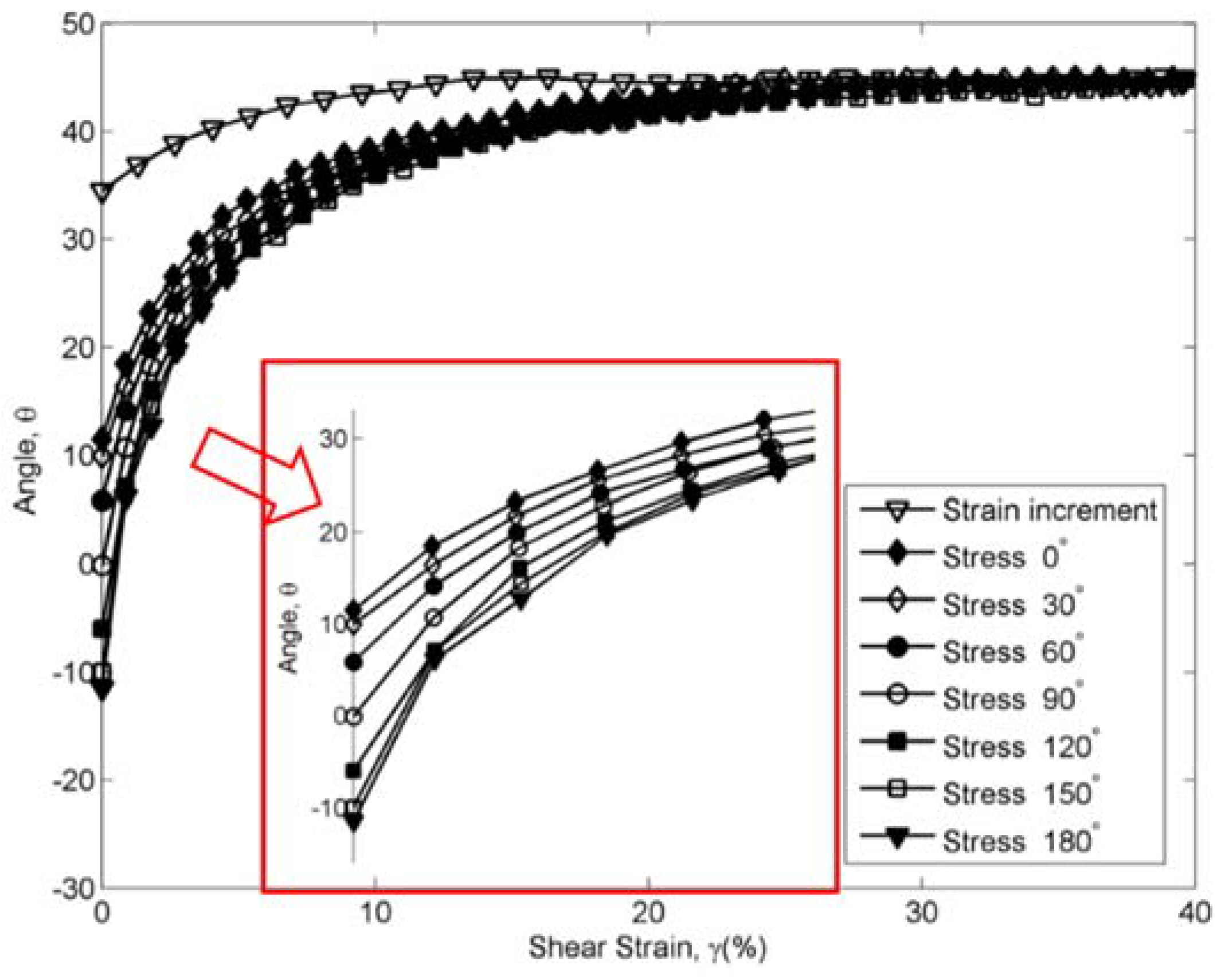
Using the same stress paths, Li et al. [60,61] studied the non-coaxiality of sand during the shear. Non-coaxiality is analyzed based on the linear relation between and , which is found in the constant load simple shear tests [41]. is the shear stress, is the vertical stress at consolidation, and is the rotation of the principal axes of stresses. The effect of relative density, vertical stress, and stress history on non-coaxiality are studied. It was found that increasing the relative density decreases the level of non-coaxiality, as shown in Figure 13, and that increasing the effective vertical stress increases the non-coaxiality, as shown in Figure 14. In addition, in the test with a different stress history, as shown in Figure 15, the greatest non-coaxiality is found in the test with the angle of 180°, and the smallest difference of these axes is found in the test with the angle of 0°. At a small shear strain, the stress history has a significant effect on the non-coaxiality, in which the increasing angle increases the level of non-coaxiality, as shown in Figure 15.
5. Conclusions
Studying the soil behavior under shear stress is a major research topic in soil mechanics, and it helps to create a better understanding of materials with soil components. Commonly utilized testing facilities are the triaxial apparatuses, hollow cylinder apparatuses, and direct simple shear apparatuses. These devices, used under various loading conditions, produce a huge number of experimental data. However, there is one salient limitation in these experiments, in that there is only one shear stress exerted on the soil samples. In most geotechnical engineering applications, the soil is often subject to shear stresses along multiple directions, such as in the embankments under earthquake strike and in the foundations of breakwaters. There is a consolidation shear stress acting along the slope due to gravity in embankments, and an earthquake strike generates another shear stress, which is generally not in line with the slope direction. The shear stress is stress path related, so it must be examined under the same stress path as in situ. However, those complex loading conditions cannot be simulated using traditional testing apparatuses.
To better understand the soil behavior under multiple shear stresses, a few researchers have developed in-house bi-directional direct simple shear apparatuses, in which two shear stresses can be exerted on a soil specimen, independently from orthogonal directions. However, the types of soil tested and the experimental data are quite limited. In addition, the magnitude and direction of the consolidation shear stresses have not been systematically studied in previous studies. Some previous works done by bi-directional direct simple shear apparatuses are summarized in Table 1.
Funding
This research is supported by the National Natural Science Foundation of China (NSFC Contract No. 51708040), the Fundamental Research Funds for the Central Universities of Ministry of Education of China (Grant No. 300102218106), and the International Doctoral Innovation Centre (IDIC) scholarship scheme. The work is also partially supported by the Engineering and Physical Sciences Research Council (EPSRC), Grant No. EP/L015463/1.
Conflicts of Interest
The author declares no conflicts of interest.
References
- Jing, P.; Nowamooz, H.; Chazallon, C. Effect of Anisotropy on the Resilient Behaviour of a Granular Material in Low Traffic Pavement. Materials 2017, 10, 1382. [Google Scholar] [CrossRef] [PubMed]
- Roozbahani, M.M.; Borela, R.; Frost, J.D. Pore Size Distribution in Granular Material Microstructure. Materials 2017, 10, 1237. [Google Scholar] [CrossRef] [PubMed]
- Qiu, J.L.; Wang, X.L.; Lai, J.X.; Zhang, Q.; Wang, J.B. Response characteristics and preventions for seismic subsidence of loess in Northwest China. Nat. Hazards 2018, 92, 1909–1935. [Google Scholar] [CrossRef]
- Montanari, D.; Agostini, A.; Bonini, M.; Corti, G.; Ventisette, C.D. The Use of Empirical Methods for Testing Granular Materials in Analogue Modelling. Materials 2017, 10, 635. [Google Scholar] [CrossRef] [PubMed]
- Mohseni, E.; Tang, W.; Cui, H. Chloride Diffusion and Acid Resistance of Concrete Containing Zeolite and Tuff as Partial Replacements of Cement and Sand. Materials 2017, 10, 372. [Google Scholar] [CrossRef] [PubMed]
- Al Mahbub, A.; Haque, A. X-ray Computed Tomography Imaging of the Microstructure of Sand Particles Subjected to High Pressure One-Dimensional Compression. Materials 2016, 9, 890. [Google Scholar] [CrossRef] [PubMed]
- Lai, J.X.; Mao, S.; Qiu, J.L.; Fan, H.B.; Zhang, Q.; Hu, Z.N.; Chen, J.X. Investigation progresses and applications of fractional derivative model in geotechnical engineering. Math. Probl. Eng. 2016, 3, 1–15. [Google Scholar] [CrossRef]
- Qiu, J.L.; Liu, H.Q.; Lai, J.X.; Lai, H.P.; Chen, J.X.; Wang, K. Investigating the long-term settlement of a tunnel built over improved loessial foundation soil using jet grouting technique. J. Perform. Constr. Facil. 2018. [Google Scholar] [CrossRef]
- Bhardwaj, B.; Kumar, P. Waste foundry sand in concrete: A review. Constr. Build. Mater. 2017, 156, 661–674. [Google Scholar] [CrossRef]
- Bourguiba, A.; Ghorbel, E.; Cristofol, L.; Dhaoui, W. Effects of recycled sand on the properties and durability of polymer and cement based mortars. Constr. Build. Mater. 2017, 153, 44–54. [Google Scholar] [CrossRef]
- Seed, H.B.; Lee, K.L. Undrained strength characteristics of cohesionless soils. J. Soil Mech. Found. Div. 1967, 93, 333–360. [Google Scholar]
- Vaid, Y.P.; Chern, J.C.L. Effect of static shear on resistance to liquefaction. Soils Found. 1983, 23, 47–60. [Google Scholar] [CrossRef]
- Ishihara, K. Liquefaction and flow failure during earthquake. Géotechnique 1993, 43, 351–415. [Google Scholar] [CrossRef]
- Sze, H.Y.; Jun, Y. Initial static shear effect on cyclic liquefaction behaviour of sand. Trans. Hong Kong Inst. Eng. 2009, 16, 56–62. [Google Scholar]
- Vaid, Y.P.; Stedman, J.D.; Sivathayalan, S. Confining stress and static shear effects in cyclic liquefaction. Can. Geotech. J. 2001, 38, 580–591. [Google Scholar] [CrossRef]
- Sivathayalan, S.; Ha, D. Effect of static shear stress on the cyclic resistance of sands in simple shear loading. Can. Geotech. J. 2011, 48, 1471–1484. [Google Scholar] [CrossRef]
- Ishihara, K. Soil Behaviour in Earthquake Geotechnics; Claredon Press: Oxford, UK, 1996. [Google Scholar]
- Tatsuoka, F.; Iwasaki, T.; Fukushima, S.; Sudo, H. Stress conditions and stress histories affecting shear modulus and damping of sand under cyclic loading. Soils Found. 1979, 19, 29–43. [Google Scholar] [CrossRef]
- Dakoulas, P.; Sun, Y. Fine Ottawa sand: Experimental behavior and theoretical predictions. J. Geotech. Eng. 1992, 118, 1906–1923. [Google Scholar] [CrossRef]
- Yang, L.T. Experimental Study of Soil Anisotropy Using Hollow Cylinder Testing. Ph.D. Thesis, University of Nottingham, Nottingham, UK, 2013. [Google Scholar]
- Sivathayalan, S.; Logeswaran, P.; Manmatharajan, V. Cyclic resistance of a loose sand subjected to rotation of principal stresses. J. Geotech. Geoenvironmental Eng. 2015, 141, 1–13. [Google Scholar] [CrossRef]
- Towhata, I.; Ishihara, K. Undrained strength of sand undergoing cyclic rotation of principal stress axes. Soils Found. 1985, 25, 135–147. [Google Scholar] [CrossRef]
- Cai, Y.Y. An Experimental Study of Non-Coaxial Soil Behaviour Using Hollow Cylinder Testing. Ph.D. Thesis, University of Nottingham, Nottingham, UK, 2010. [Google Scholar]
- Cai, Y.Y.; Yu, H.S.; Wanatowski, D.; Li, X. Noncoaxial Behavior of Sand under Various Stress Paths. J. Geotech. Geoenviron. Eng. 2013, 139, 1381–1395. [Google Scholar] [CrossRef]
- Budhu, M. The mechanics of failure under cyclic simple shear strain. Soils Found. 1988, 28, 119–129. [Google Scholar] [CrossRef]
- Roscoe, K. An apparatus for the application of simple shear to soil samples. In Proceedings of the 3rd International Conference in Soil Mechanics and Foundation Engineering, Zurich, Switzerland, 16–27 August 1953; Volume 1, pp. 186–191. [Google Scholar]
- Bjerrum, L.; Landva, A. Direct simple-shear tests on a Norwegian quick clay. Géotechnique 1966, 16, 1–20. [Google Scholar] [CrossRef]
- Franke, E.; Kiekbusch, M.; Schuppener, B. A new direct simple shear device. Geotech. Test. J. 1979, 2, 190–199. [Google Scholar]
- Ishihara, K.; Yamazaki, F. Cyclic simple shear tests on saturated sand in multi-directional loading. Soils Found. 1980, 20, 45–59. [Google Scholar] [CrossRef]
- Boulanger, R.W.; Chan, C.K.; Seed, H.B.; Seed, R.B. A Low-compliance bi-directional cyclic simple shear apparatus. Geotech. Test. J. 1993, 16, 36–45. [Google Scholar]
- Baxter, C.D.P.; Bradshaw, A.S.; Ochoa-Lavergne, M.; Hankour, R. DSS test results using wire-reinforced membranes and stacked rings. Geotech. Spec. Publ. 2010, 199, 600–607. [Google Scholar]
- Kwan, W.; EI Mohtar, C. Comparison between shear strength of dry sand measured in CSS device using wire-reinforced membranes and stacked rings. In Proceedings of the Geo-Congress (ASCE), Atlanta, GA, USA, 23–26 February 2014; pp. 1111–1119. [Google Scholar]
- Moussa, A. Radial Stresses in Sand in Constant Volume Static and Cyclic Simple Shear Tests; Internal Report No. 51505-10; Norwegian Geotechnical Institute: Oslo, Norway, 1974. [Google Scholar]
- Dyvik, R.; Zimmie, T.F.; Floess, C.H.L. Lateral stress measurements in direct simple shear device. Lab. Shear Strength Soils 1981, 740, 191–206. [Google Scholar]
- Dyvik, R.; Zimmie, T.F. Lateral stress measurements during static and cyclic direct simple shear testing. In Proceedings of the 3rd International Conference on the Behavior of Off–Shore Structures, Cambridge, UK; 1982; Volume 2, pp. 363–372. [Google Scholar]
- Matsuda, H.; Nhan, T.T.; Ishikura, R. Prediction of excess pore water pressure and post-cyclic settlement on soft clay induced by uni-directional and multi-directional cyclic shears as a function of strain path parameters. Soil Dyn. Earthq. Eng. 2013, 49, 75–88. [Google Scholar] [CrossRef]
- Kammerer, A. Undrained Response of Monterey 0/30 Sand under Multidirectional Cyclic Simple Shear Loading Conditions. Ph.D. Thesis, University of California, Berkeley, CA, USA, 2002. [Google Scholar]
- Boulanger, R.W.; Seed, R.B. Liquefaction of sand under bidirectional monotonic and cyclic loading. J. Geotech. Eng. 1995, 121, 870–878. [Google Scholar] [CrossRef]
- Finn, W.D.L. Aspects of constant volume cyclic simple shear. In Advances in the Art of Testing Soils under Cyclic Conditions; ASCE Convention: Detroit, MI, USA, 1985; pp. 74–98. [Google Scholar]
- Dyvik, R.; Berre, T.; Lacasse, S.; Raadim, B. Comparison of truly undrained and constant volume direct simple shear tests. Géotechnique 1987, 37, 3–10. [Google Scholar] [CrossRef]
- Budhu, M. Lateral stresses observed in two simple shear apparatus. J. Geotech. Eng. 1985, 111, 698–711. [Google Scholar] [CrossRef]
- Boulanger, R.; Chan, C.; Seed, H.; Seed, R.; Sousa, J.A. Low-Compliance BiDirectional Cyclic Simple Shear Apparatus. Geotech. Test. J. 1993, 16, 36–45. [Google Scholar]
- Jaime, A. A two-direction cyclic shear apparatus. In Proceedings of the 5th Pan American Conference on Soil Mechanics and Foundation Engineering, Buenos Aires, Argentine, 17–22 November 1975; Volume 2, pp. 395–402. [Google Scholar]
- Casagrande, A.; Rendon, F. Gyratory Shear Apparatus, Design, Testing Procedures; Technical Report No. S-78-i5; Corps of Engineers Waterways Experiment Station: Vicksburg, MS, USA, 1978. [Google Scholar]
- DeGroot, D.J.; Germaine, J.T.; Ladd, C.C. The multidirectional direct simple shear apparatus. Geotech. Test. J. 1993, 16, 283–295. [Google Scholar]
- Rutherford, C.J. Development of a Multi-Directional Direct Simple Shear Testing Device for Characterization of the Cyclic Shear Response of Marine Clays. Ph.D. Thesis, Texas A&M University, College Station, TX, USA, 2012. [Google Scholar]
- Biscontin, G. Modeling the Dynamic Behavior of Lightly Overconsolidated Soil Deposits on Submerged Slopes. Ph.D. Thesis, University of California, Berkeley, CA, USA, 2001. [Google Scholar]
- Harder, L.F.; Boulanger, R.W. Application of Kσ and Kα correction factors. In Proceedings of the NCEER Workshop on Evaluation of Liquefaction Resistance of Soils; Technical Report NCEER-97-0022; Youd, T.L., Idriss, I.M., Eds.; National Center for Earthquake Engineering Research, SUNY: Buffalo, NY, USA, 1997; pp. 167–190. [Google Scholar]
- Idriss, I.M.; Boulanger, R.W. Estimating Kα for use in evaluating cyclic resistance of sloping ground. In Proceedings, 8th US-Japan Workshop on Earthquake Resistant Design of Lifeline Facilities and Countermeasures against Liquefaction; Report MCEER-03-0003; Hamada, O., Bardet, Eds.; MCEER, SUNY: Buffalo, NY, USA, 2003; pp. 449–468. [Google Scholar]
- Boulanger, R.W.; Seed, R.B.; Chan, C.K. Effects of Initial Static Driving Shear Stresses on the Liquefaction Behavior of Saturated Cohesionless Soils; Technical Report No. UCB/GT/91-01; University of California: Berkeley, CA, USA, 1991. [Google Scholar]
- Boulanger, R.W.; Seed, R.B.; Chan, C.K.; Seed, H.B.; Sousa, J.B. Liquefaction Behavior of Saturated Sands under Uni-Directional and Bi-Directional Monotonic and Cyclic Simple Shear Loading; Technical Report No. UCB/GT-91/08; University of California: Berkeley, CA, USA, 1991. [Google Scholar]
- Seed, H.B.; Idriss, I.M.; Makdisi, F.I.; Banerjee, N.G. Representation of Irregular Stress Time Histories by Equivalent Uniform Stress Series in Liquefaction Analysis; Technical Report No. EERC75-29; University of California Berkeley: Berkeley, CA, USA, 1975. [Google Scholar]
- Ishihara, K.; Nagase, H. Multi-directional irregular loading tests on sand. Soil Dyn. Earthq. Eng. 1988, 7, 201–212. [Google Scholar] [CrossRef]
- Matsuda, H.; Hendrawan, A.P.; Ishikura, R.; Kawahara, S. Effective stress change and post-earthquake settlement properties of granular materials subjected to multi-directional cyclic simple shear. Soils Found. 2011, 51, 873–884. [Google Scholar] [CrossRef]
- Matsuda, H.; Shinozaki, H.; Okada, N.; Takamiya, K.; Shinyama, K. Effects of multi-directional cyclic shear on the post-earthquake settlement of ground. In Proceedings of the 13th World Conference on Earthquake Engineering, Vancouver, BC, Canada, 1–6 August 2004. Paper No. 2890. [Google Scholar]
- DeGroot, D.J.; Ladd, C.C.; Germaine, J.T. Undrained multidirectional direct simple shear behavior of cohesive soil. J. Geotech. Eng. 1996, 122, 91–98. [Google Scholar] [CrossRef]
- Li, Y.; Yang, Y.; Yu, H.; Roberts, G. Monotonic Direct Simple Shear Tests on Sand under Multidirectional Loading. Int. J. Geomech. 2017, 17, 1–10. [Google Scholar] [CrossRef]
- Li, Y.; Yang, Y.; Yu, H.; Roberts, G. Effect of Sample Reconstitution Methods on the Behaviors of Sand under Shearing. J. Test. Eval. 2018, 46, 1–8. [Google Scholar] [CrossRef]
- Li, Y.; Yang, Y.; Yu, H.; Roberts, G. Correlations between the stress paths of a monotonic test and a cyclic test under the same initial conditions. Soil Dyn. Earthq. Eng. 2017, 101, 153–156. [Google Scholar] [CrossRef]
- Li, Y.; Yang, Y.; Yu, H.; Roberts, G. Principal Stress Rotation under Bidirectional Simple Shear Loadings. KSCE J. Civ. Eng. 2018, 22, 1651–1660. [Google Scholar] [CrossRef]
- Li, Y.; Yang, Y. Non-coaxiality of sand under bi-directional shear loading. R. Soc. Open Sci. 2018, 5, 172076. [Google Scholar] [CrossRef] [PubMed] [Green Version]
Figure 1.
Schematic of a bi-directional simple shear testing apparatus (a) YZ plane (b) XZ plane [52].
Figure 1.
Schematic of a bi-directional simple shear testing apparatus (a) YZ plane (b) XZ plane [52].

Figure 2.
Sectional details of a specimen in a mould [52].
Figure 2.
Sectional details of a specimen in a mould [52].

Figure 3.
Stress paths in the bi-directional simple shear tests (a) rotational loadings and (b) alternate shear loadings (Reprinted from [29]).
Figure 3.
Stress paths in the bi-directional simple shear tests (a) rotational loadings and (b) alternate shear loadings (Reprinted from [29]).
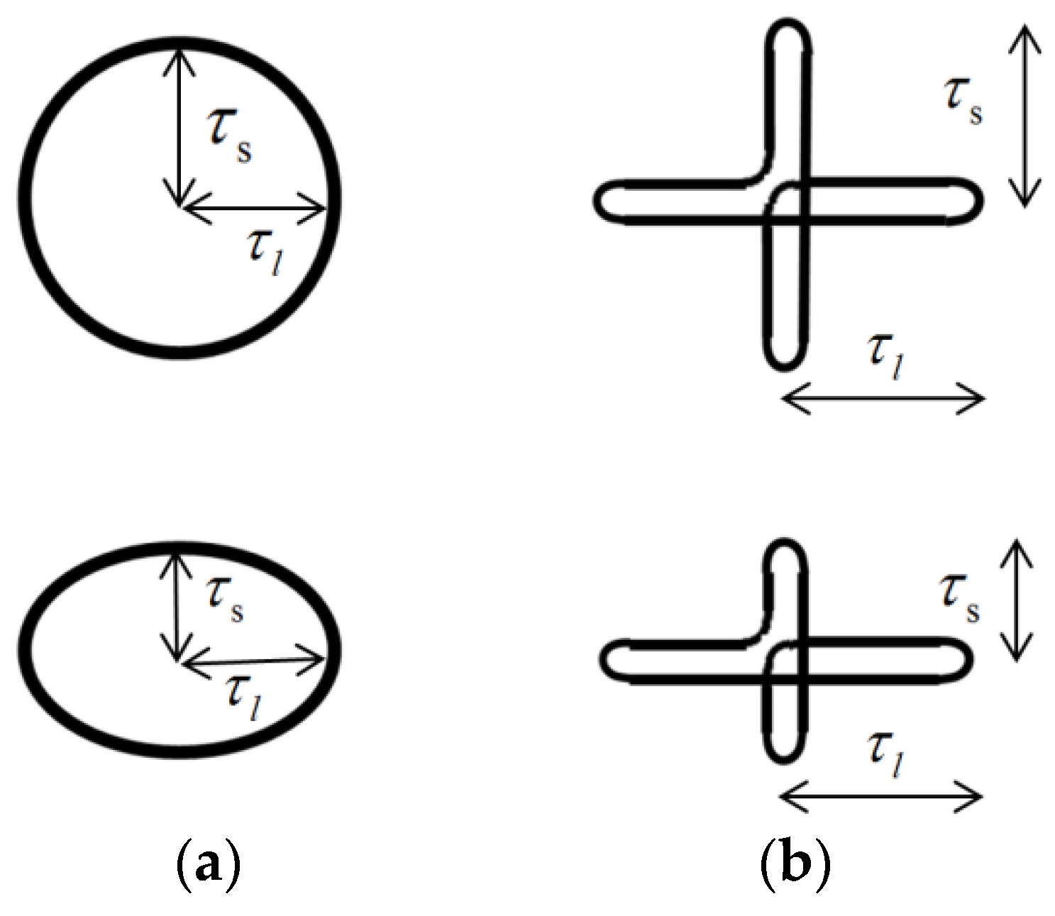
Figure 4.
Waves of (a) uni-directional shear loadings and (b) multidirectional shear-circular loading (Reprinted from [29]).
Figure 4.
Waves of (a) uni-directional shear loadings and (b) multidirectional shear-circular loading (Reprinted from [29]).

Figure 5.
The maximum normalized shear stresses and total shear stresses versus θ ( = 0.2) (Reprinted from [55]).
Figure 5.
The maximum normalized shear stresses and total shear stresses versus θ ( = 0.2) (Reprinted from [55]).
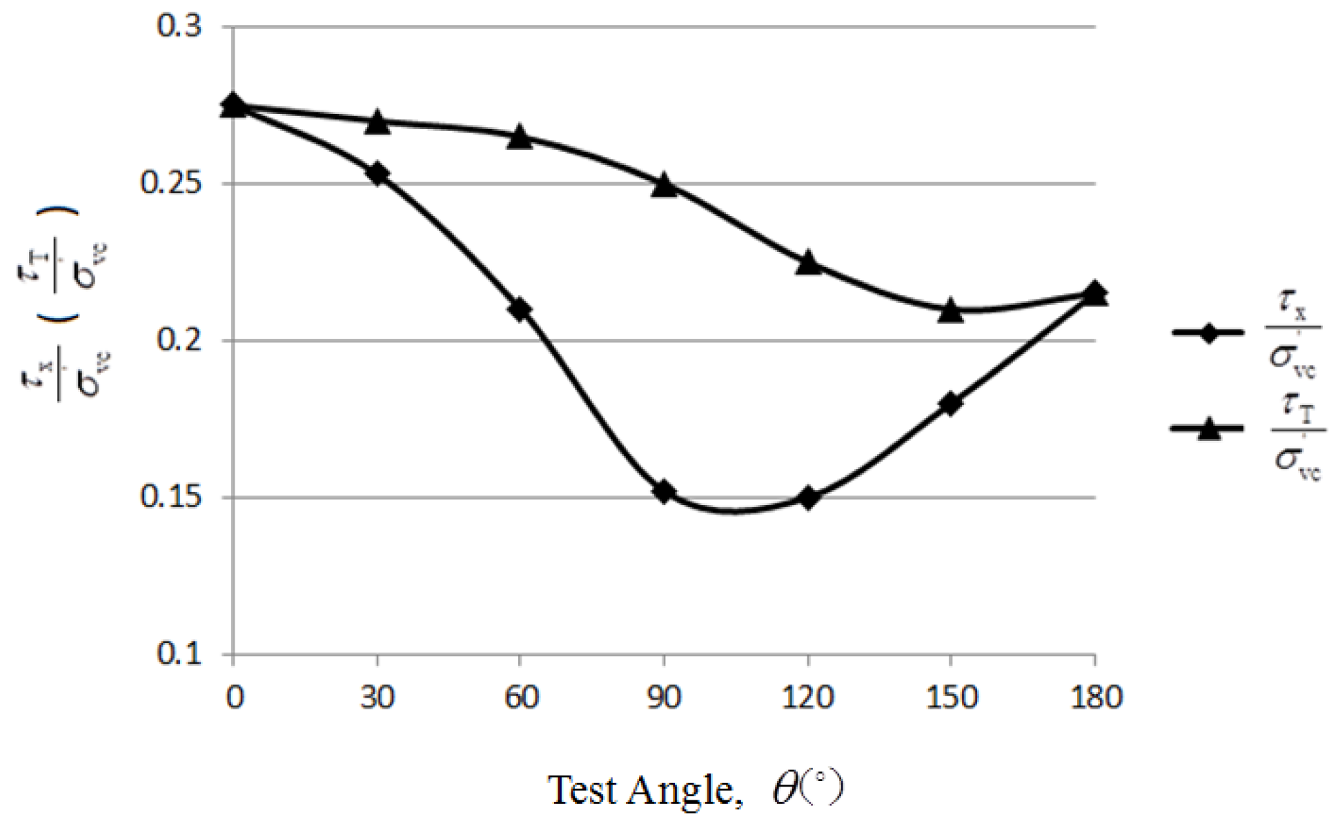
Figure 6.
Two dynamic loading conditions considered in the tests (Reprinted from [38]).
Figure 6.
Two dynamic loading conditions considered in the tests (Reprinted from [38]).

Figure 7.
Multi-directional loadings considered the initial static driving force, tested by Kammerer (Reprinted from [37]).
Figure 7.
Multi-directional loadings considered the initial static driving force, tested by Kammerer (Reprinted from [37]).

Figure 8.
Different levels of stress reversals in tests with varied stress paths, by Kammerer (Reprinted from [37]).
Figure 8.
Different levels of stress reversals in tests with varied stress paths, by Kammerer (Reprinted from [37]).
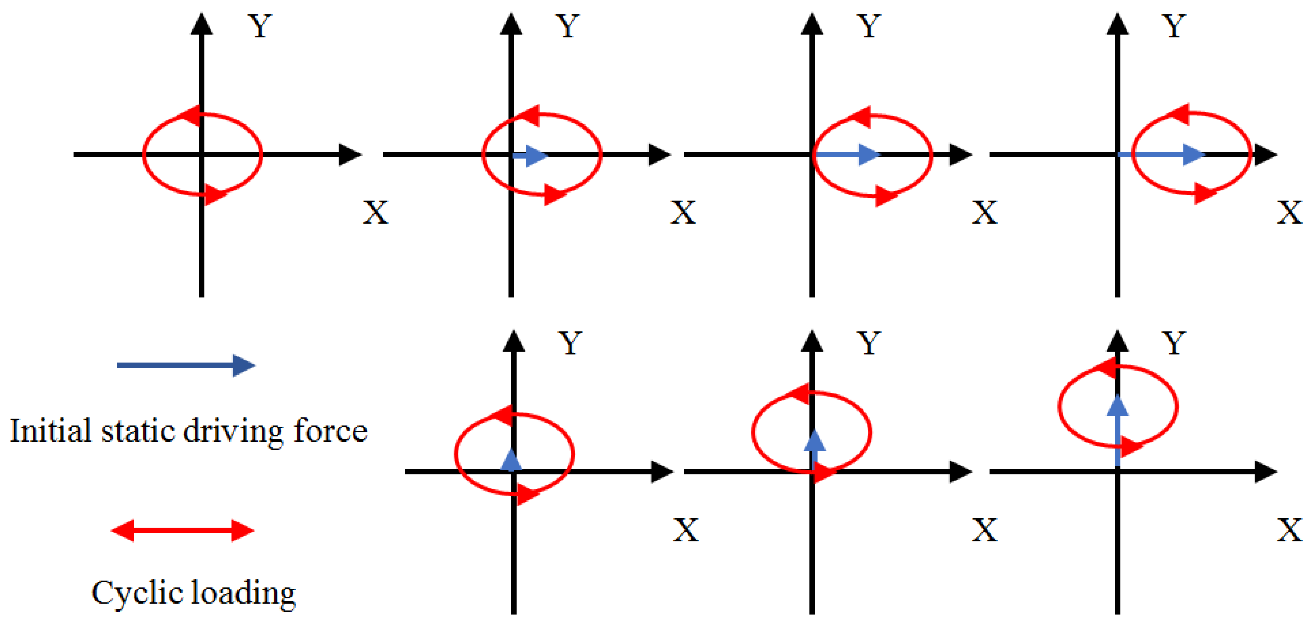
Figure 9.
Cyclic shear strain and permanent shear strain in a simple shear test (Reprinted from [37]).
Figure 9.
Cyclic shear strain and permanent shear strain in a simple shear test (Reprinted from [37]).
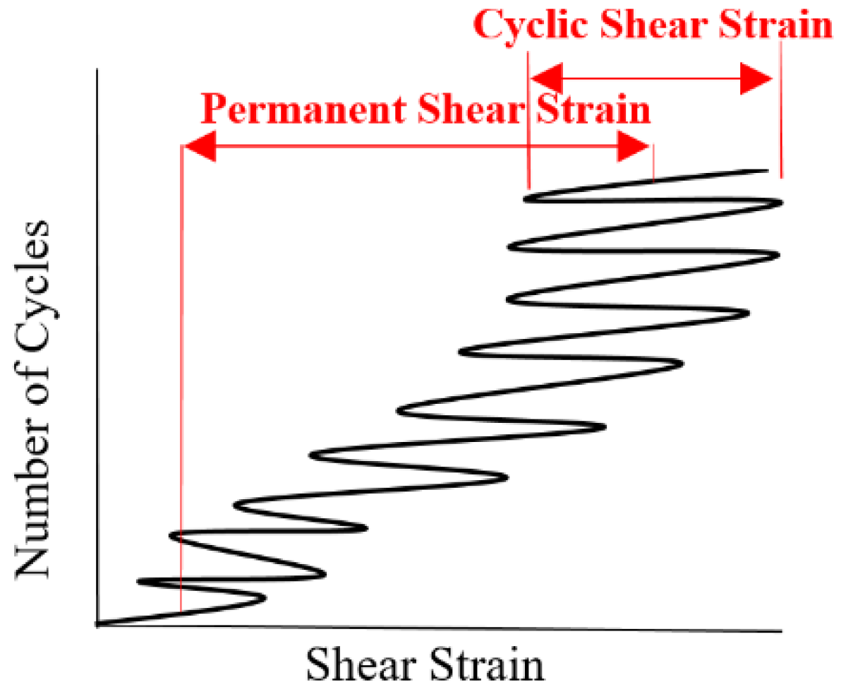
Figure 10.
Limiting pore water pressure in a simple shear test (Reprinted from [37]).
Figure 10.
Limiting pore water pressure in a simple shear test (Reprinted from [37]).

Figure 11.
Stress paths on soil samples including the first consolidation shear stress, followed by undrained shear [52].
Figure 11.
Stress paths on soil samples including the first consolidation shear stress, followed by undrained shear [52].
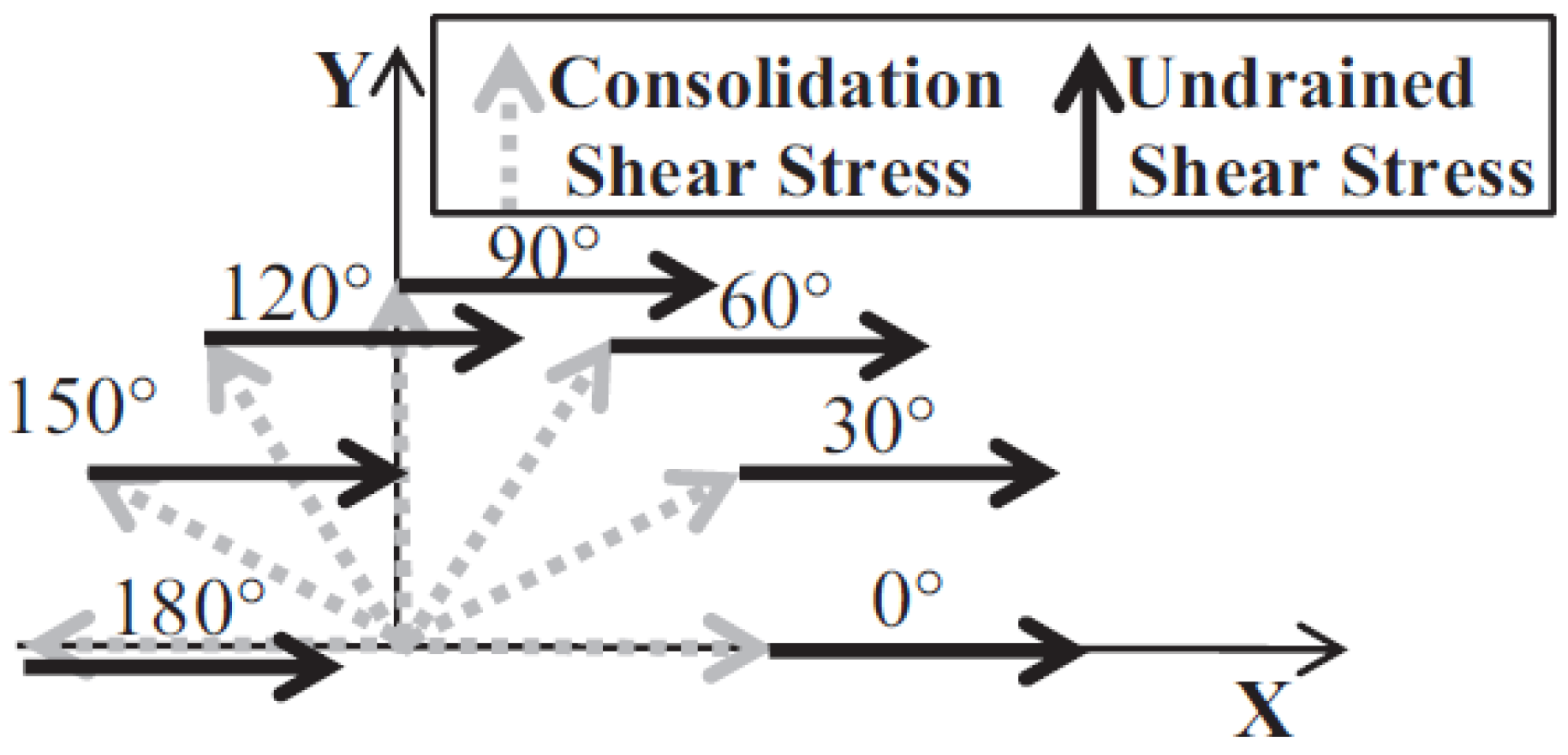
Figure 12.
Shear strength along the x-direction and the total shear strength for the different angles of shear consolidation under the consolidation shear stress ratio (CSRs) of 0.05 and 0.1 [52].
Figure 12.
Shear strength along the x-direction and the total shear strength for the different angles of shear consolidation under the consolidation shear stress ratio (CSRs) of 0.05 and 0.1 [52].

Figure 13.
Rotation of principal axes of stresses and strain increment at different relative densities [60].
Figure 13.
Rotation of principal axes of stresses and strain increment at different relative densities [60].
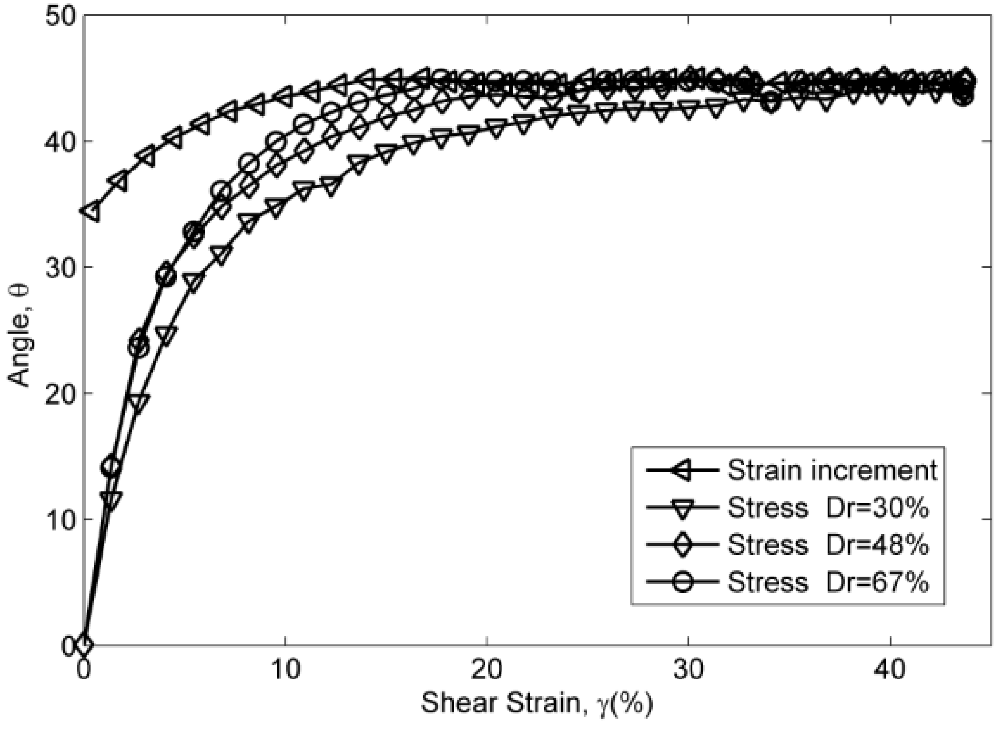
Figure 14.
Rotation of principal axes of stresses and strain increment under different vertical stresses [60].
Figure 14.
Rotation of principal axes of stresses and strain increment under different vertical stresses [60].
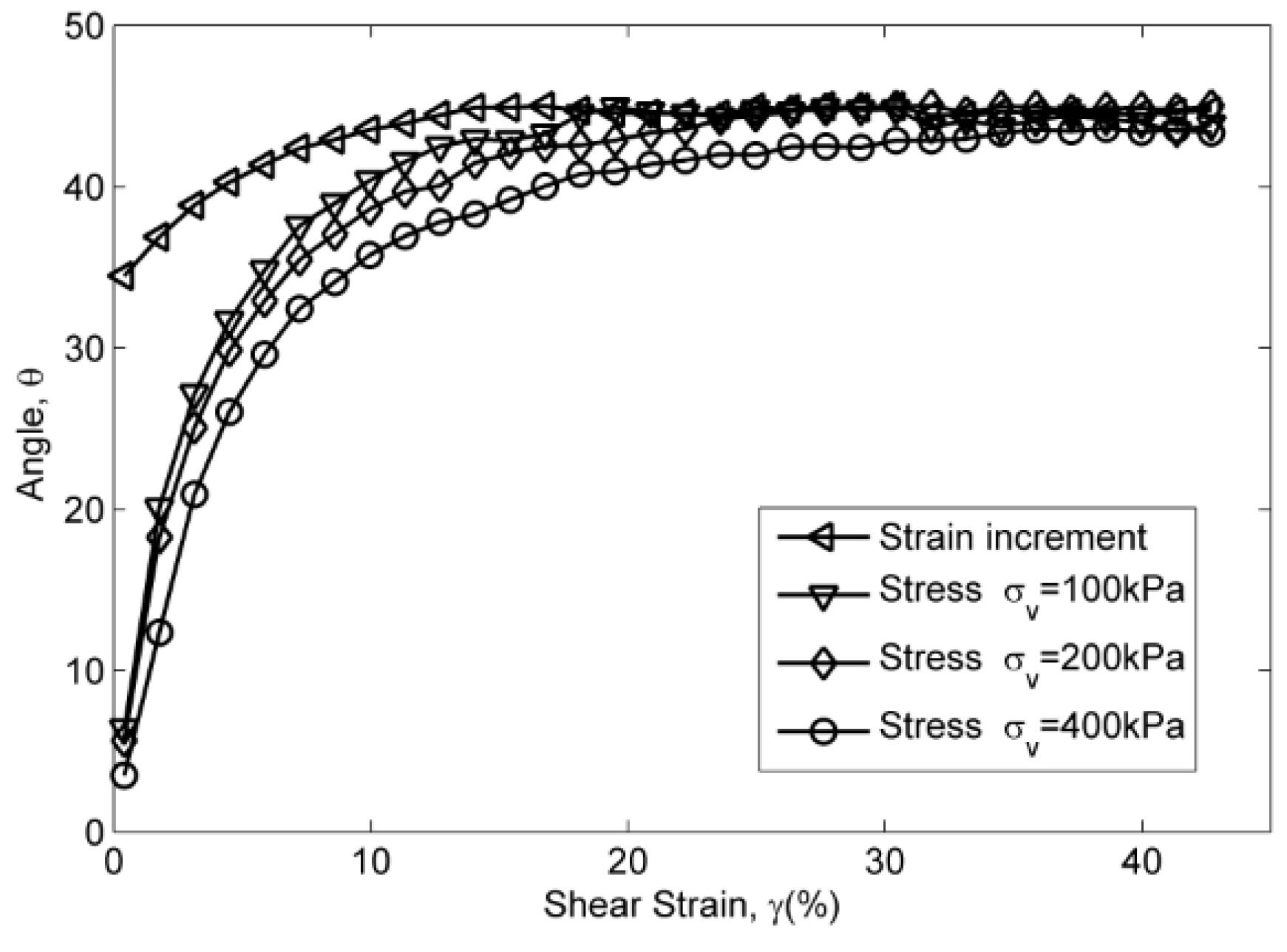
Figure 15.
Rotation of principal axes of stresses and strain increment in different stress paths at CSR=0.1 [60].
Figure 15.
Rotation of principal axes of stresses and strain increment in different stress paths at CSR=0.1 [60].

Table 1.
Some previous works done by bi-directional direct simple shear apparatuses.
| Authors (Year) | Tested Materials | Tested Stress Paths | Findings |
|---|---|---|---|
| Ishihara and Yamazaki (1980) | Fuji River Sand | 1. Circular cyclic loading. 2. Elliptic cyclic loading. 3. Alternating cyclic loading. * Truly undrained test | 1. Increasing secondary shear stress decreases liquefaction resistance. 2. Rocking motions exists. |
| Ishihara and Nagase (1988) | Fuji River Sand | Irregular shear stress: time histories of horizontal accelerations of recorded ground surface during few earthquakes. * Truly undrained test | 1. Increasing secondary shear stress decreases liquefaction resistance, and irregular loading increased the liquefaction resistance. 2. Rocking motions still exists. |
| Boulanger and Seed (1995) | Modified Sacramento River Sand | Drained monotonic shear (in X and Y direction) and secondary undrained cyclic shear (in X direction). * Constant volume test | 1. When the two stresses are in the same direction, liquefaction resistance usually increases with increasing the consolidation shear stress. 2. When cyclic shear stress is applied perpendicular to the consolidation shear stress, liquefaction resistance decreases with increasing consolidation shear stress. |
| DeGroot et al. (1996) | Boston Blue Clay | Drained monotonic shear (in 0°-180°to X direction) directions + secondary undrained monotonic shear(in X direction). * Constant volume test | Peak shear strength (in X direction) decreases dramatically in tests with an angle from 0° to 120°, and then increases in tests with an angle from 120° to 180°. |
| Biscontin (2001) | Young Bay Mud | 1. Drained monotonic shear (in 0°–180°to X direction) directions + secondary undrained monotonic shear (in X direction). 2. Drained monotonic shear (in 0°and 90°to X direction) directions + secondary undrained cyclic shear (in X direction). * Truly undrained test | 1. Consolidation shear stress and its loading angle to secondary undrained monotonic shear stress have effect on shear behavior. 2. Undrained monotonic shear strength increases with increasing consolidation shear stress. 3. Shear strain development (magnitude and direction) is different in cyclic tests with different stress histories. |
| Kammerer (2002) | Monterey #30 Sand | 1. One-directional cyclic loading. 2. Circular/elliptic cyclic loading. 3. Figure 8 cyclic loading. With 0° and 90° consolidation shear stress. * Truly undrained test | 1. Cyclic shear strength in a bi-directional simple shear is more complex than a one-directional simple shear test. 2. Reduction factors, developed by Seed et al. [57], and Ishihara and Yamazaki [29], may not reflect the differences in liquefaction triggering between a one-directional simple test and a corresponding uni-directional simple shear test under the same testing conditions. |
| Matsuda et al. (2011) | Toyoura Sand and GBFS | 1. One-directional cyclic loading. 2. Circular cyclic loading. * Constant volume test | 1. Generally, the amplitude of shear displacement has a significant effect on the changes of the effective stress of Toyoura sand and GBFS. 2. At a higher amplitude of shear displacement, cyclic shear direction has little effect on effective stress. |
| Rutherford (2012) | Mexico Gulf Clay | 1. Monotonic test. 2. One-directional cyclic loading. 3. Circular cyclic loading. 4. Figure 8 cyclic loading. * Truly undrained test | 1. Stress reversal affects excess pore water pressure generation. 2. Figure 8 tests accumulate permanent strain faster than other stress paths. |
| Matsuda et al. (2013) | Kaolinite Clay | 1. One-directional cyclic loading. 2. Circular cyclic loading. 3. Elliptic cyclic loading with different phase differences. * Constant volume test | 1. At the same amplitude of the shear displacement and number of cycles, excess pore water pressure and post-liquefaction settlement caused during multi-directional loading is greater than that under one-directional loading. 2. Excess pore water pressure and post-liquefaction settlement caused during multi-directional loading is increased by phase difference. |
| Li et al. (2017) | Leighton Buzzard Sand Fraction B | Drained monotonic shear (in 0°–180°to X direction) directions and secondary undrained monotonic shear (in X direction). * Constant volume test | 1. Magnitude of consolidation shear stress ratio affects the shear behavior. 2. Consolidation shear stress densifies the soil samples, and the role of densification is predominant over the role of angles under a small consolidation shear stress ratio. |
| Li et al. (2018) | Leighton Buzzard Sand Fraction B | Drained monotonic shear (in 0°–180°to X direction) directions and secondary undrained monotonic shear (in X direction). * Constant volume test | 1. Increasing the relative density decreases the level of non-coaxiality, and increasing the effective vertical stress increases the non-coaxiality. 2. The greatest non-coaxiality is found in the test with the angle of 180°, and the smallest difference of these axes is in the test with the angle of 0°. |
* Truly undrained test denotes tests with pore pressure measurement, and Constant volume test denotes tests without pore pressure measurement.
© 2018 by the author. Licensee MDPI, Basel, Switzerland. This article is an open access article distributed under the terms and conditions of the Creative Commons Attribution (CC BY) license (http://creativecommons.org/licenses/by/4.0/).
Share and Cite
MDPI and ACS Style
Li, Y. Test Granular Materials Failure Using Bi-Directional Simple Shear Apparatus: A Review. Appl. Sci. 2018, 8, 1140. https://doi.org/10.3390/app8071140
AMA Style
Li Y. Test Granular Materials Failure Using Bi-Directional Simple Shear Apparatus: A Review. Applied Sciences. 2018; 8(7):1140. https://doi.org/10.3390/app8071140
Chicago/Turabian StyleLi, Yao. 2018. "Test Granular Materials Failure Using Bi-Directional Simple Shear Apparatus: A Review" Applied Sciences 8, no. 7: 1140. https://doi.org/10.3390/app8071140
Note that from the first issue of 2016, this journal uses article numbers instead of page numbers. See further details here.