Article

Mode-Matching-Based Sound Field Recording and Synthesis with Circular Double-Layer Arrays

National Institute of Information and Communications Technology, 3-5, Hikaridai, Seika-cho, Soraku-gun, Kyoto 619-0289, Japan
Appl. Sci. 2018, 8(7), 1084; https://doi.org/10.3390/app8071084
Submission received: 30 May 2018 / Revised: 28 June 2018 / Accepted: 3 July 2018 / Published: 4 July 2018
(This article belongs to the Section Acoustics and Vibrations)

Abstract

:
A sound field control approach is investigated for recording a primary sound field and synthesizing it at a secondary field without exterior radiation using circular double-layer arrays of microphones and loudspeakers. Although the conventional least-squares (LS) and generalized singular value decomposition (GSVD) approaches are based on numerical solutions and control the discretized interior and exterior sound pressures, this paper provides a mode-matching-based analytical method with circular double-layer receiver and source. The primary sound field cylindrical harmonic spectrum is analytically estimated from the recorded sound pressures without forbidden frequencies, and the driving signals of the loudspeakers for synthesizing it are analytically derived without interior and exterior control points. Computer simulations demonstrate the effectiveness of the proposed analytical formulation with circular double-layer arrays of microphones and loudspeakers. Compared to the conventional numerical LS and GSVD approaches, the interior sound field synthesis is more accurate and the exterior sound propagation is more effective in the proposed method under both free-field and reverberant conditions.

1. Introduction

Generating acoustically bright and dark zones is an important and attractive problem for acoustic communication technology, and many approaches are being investigated [1,2,3,4,5,6,7,8,9,10,11,12,13,14,15]. Although these methods only control the acoustic contrast or energy between the bright and dark zones, multizone sound field synthesis methods also simultaneously control not only the sound pressures but also multiple sound fields in multiple regions [16,17,18,19,20,21,22,23,24,25].
Most sound field synthesis approaches assume that the synthesis environment is a free-field and the synthesis target area is inside the loudspeaker array [26,27,28,29,30]. Figure 1a shows an example of a two-dimensional interior sound field synthesis based on higher-order Ambisonics [29] with a circular loudspeaker array in a free-field. Although a plane wave is synthesized inside the array, undesired sound pressures propagate outside the array. In addition, the actual synthesis environment is not a free-field, and reverberation occurs by undesired sound pressures propagating outside the array. Consequently, reverberation degrades the synthesis accuracy in the target area (Figure 1b). Therefore, considering the sound pressures propagating outside the array is important both to reduce the undesired sound propagation and to maintain the synthesis accuracy in the target area in the actual reverberant conditions.
Considering the reverberant conditions, exterior propagation-free sound field synthesis approaches have been proposed [31,32,33,34]. These approaches can synthesize a sound field inside an array without propagating undesired sound pressures outside the array (Figure 1c). As a result, reverberations do not occur, and the synthesis accuracy inside the array remains high in actual reverberant conditions. These methods are categorized as multizone sound field control approaches where the synthesized and acoustically dark zones are simultaneously set inside and outside the array. In these methods, the synthesized sound field is assumed to be a simple plane wave. To extend exterior propagation-free sound field synthesis for reproducing a primary sound field recorded by a microphone array [35], this paper focuses on sound field recording and synthesis methods without exterior propagation using arrays of microphones and loudspeakers.
To achieve such a sound field recording and synthesis approach, pressure matching-based least-squares (LS) [36,37] and generalized singular value decomposition (GSVD) [38] methods [39] are directly introduced. The LS and GSVD methods are based on the Kirchhoff–Helmholtz (KH) integral [40] and introduce double-layer arrays of microphones and loudspeakers. The LS method is, however, based on numerical inversion and requires repeated calculations to select the optimal regularization parameters. In the GSVD approach, iterative calculations are also required for finding the optimal threshold to automatically decide the singular value truncation parameters [40].
In previous works [14,34,41,42], the spatial Fourier transform-based analytical approaches to sound field control without repeated calculations outperformed the conventional LS methods in terms of control accuracy.
For more accurate interior sound field synthesis without exterior sound propagation than the conventional LS and GSVD approaches without iterative computations, this paper proposes an analytical approach with continuous circular double-layer source and receiver. The continuous circular double-layer source and receiver are finally discretized to circular double-layer arrays of microphones and loudspeakers. The proposed method is based on cylindrical harmonic expansion, which is a spatial Fourier transformation in cylindrical coordinates that is categorized as a mode-matching scheme. Although the conventional LS and GSVD methods require interior and exterior discretized control points, the proposed method does not, since a mode matching-based method controls the cylindrical harmonic spectrums of the interior and exterior sound fields as control points instead of the sound pressures.
As in the GSVD method [39], the proposed method is also formulated in a two-dimensional height-invariant sound field with a two-dimensional Green’s function, circular double-layer arrays, and cylindrical harmonic expansion. The proposed analytical method can also be easily extended for three-dimensional sound fields by introducing the three-dimensional Green’s function, spherical double-layer arrays, and spherical harmonic expansion.
The rest of this paper is organized as follows. Section 2 briefly introduces the conventional LS and GSVD methods. The proposed formulation for circular double-layer source and receiver is analytically derived in Section 3. In Section 4, computer simulations compare the proposal with the conventional LS and GSCD methods in both the free-field and reverberant conditions. Section 5 finally concludes this paper.

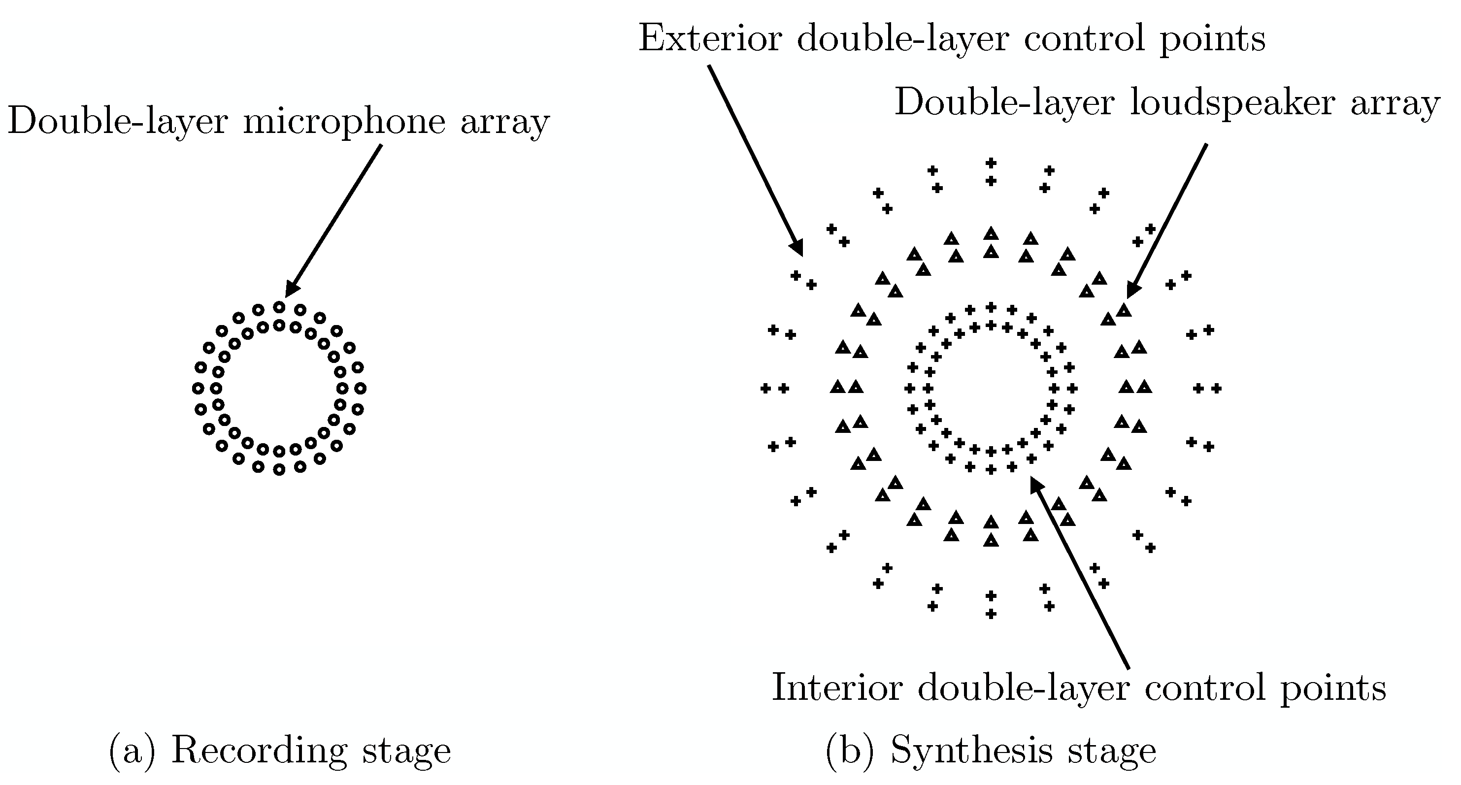
2. Pressure Matching-Based Sound Field Recording and Synthesis without Exterior Propagation with Double-Layer Arrays

The conventional LS- and GSVD-based sound field recording and synthesis methods are briefly introduced here for comparison with the proposed approach.

2.1. Kirchhoff–Helmholtz Integral

Let S be a two-dimensional volume without sound sources, bounded by surface δ S . Sound pressure P ( r , k ) at point r for wavenumber k = 2 π f / c is uniquely defined from sound pressures P ( r 0 , k ) and particle velocities P ( r 0 , k ) / n at boundary δ S by the KH integral [40]:
α P ( r , k ) = S P ( r 0 , k ) n G ( r , r 0 , k ) P ( r 0 , k ) G ( r , r 0 , k ) n d r 0 ,
where α = 1 if r is inside S, α = 1 / 2 if r is on δ S and α = 0 if r is outside S. f and c are the temporal frequency and the speed of sound, respectively. The two-dimensional free-field Green’s function is given:
G ( r , r 0 , k ) = j 4 H 0 ( k | r r 0 | ) ,
where j = 1 and H m is the m-th order Hankel function of the first kind. In the conventional LS and GSVD methods for recording a primary sound field and synthesizing it without exterior propagation, double-layer receivers and secondary sources are, respectively, introduced to achieve monopole and approximated dipole distributions on δ S and simultaneously control both the sound pressures and their derivatives based on the KH integral.

2.2. Least-Squares Approach

In the recording stage, a primary sound field is first recorded by using a double-layer array of I int microphones (Figure 2a).
In the synthesis stage, two double-layer arrays of I int and I ext control points are arranged for simultaneously controlling both the interior and exterior sound fields. In pressure matching approaches, the arrangement of the interior control points is just the same as that of the microphone array in the primary sound field. A secondary sound field is then controlled by a double-layer array of L loudspeakers located between the interior and exterior control points with driving signals of L × 1 vector D ( k ) (Figure 2b). The secondary sound pressures at the control points are defined as I ( = I int + I ext ) × 1 vectors P ( k ) and given:
P ( k ) = G ( k ) D ( k ) ,
where G ( k ) is the I × L transfer function matrix between the receivers and the sources whose coefficients are given:
G i l ( k ) = j 4 H 0 ( k | r i r l | ) .
To achieve interior sound field synthesis without exterior sound propagation, the target secondary sound pressures are set:
P ( k ) = 0 , outside the loudspeaker array P org ( k ) , inside the loudspeaker array ,
where P org ( k ) is the I int × 1 vector of the primary sound pressures captured by the microphone array. The optimal driving signals are then derived based on the least-squares solution:
D LS ( k ) = ( G H ( k ) G ( k ) ) 1 G H ( k ) P ( k ) ,
where D LS ( k ) is the driving signal for the LS method and G H ( k ) is the Hermitian transpose of G ( k ) . With the derived driving signals, both the interior and exterior sound fields are simultaneously controlled.

2.3. Generalized Singular Value Decomposition Approach

In the GSVD approach [39], G ( k ) is also decomposed into interior component G int ( k ) and exterior component G ext ( k ) :
G ( k ) = G ext ( k ) G int ( k ) .
GSVD is applied to Equation (7). G int ( k ) and G ext ( k ) are then decomposed:
G ext ( k ) = U ( k ) C ( k ) X H ( k ) ,
G int ( k ) = V ( k ) S ( k ) X H ( k ) ,
where U and V are complex unitary matrices, X is a complex square invertible matrix, and C and S are pseudo-diagonal matrices containing singular values:
C H ( k ) C ( k ) + S H ( k ) S ( k ) = I ,
where I is the L × L identity matrix. The optimal driving signals of the GSVD method are obtained:
D GSVD ( k ) = ( X H ) 1 ( k ) S K + ( k ) V H ( k ) P org ( k ) ,
where S K ( k ) retains the first K largest coefficients of S ( k ) along the diagonal and S K + ( k ) is the generalized inverse of S K ( k ) . The tradeoff between the interior field synthesis accuracy and the exterior field propagation reduction can be controlled by singular value truncation parameter K. As in a previous work [39], K was automatically chosen to satisfy that all diagonal terms of C K ( k ) are smaller than 0.01 where C K ( k ) also retains the first K smallest coefficients of C ( k ) along the diagonal. When K = L , the GSVD method just corresponds to the LS approach. The detailed derivation of the GSVD approach was previously described [39].

3. Proposed Analytical Formulation

In the LS and GSVD methods, the discretized primary interior sound pressures recorded by a double-layer microphone array are directly controlled. The proposed approach, on the other hand, controls the cylindrical harmonic spectrum of the estimated primary interior sound field rather than the discretized sound pressures. As a result, the proposal does not require interior and exterior control points.

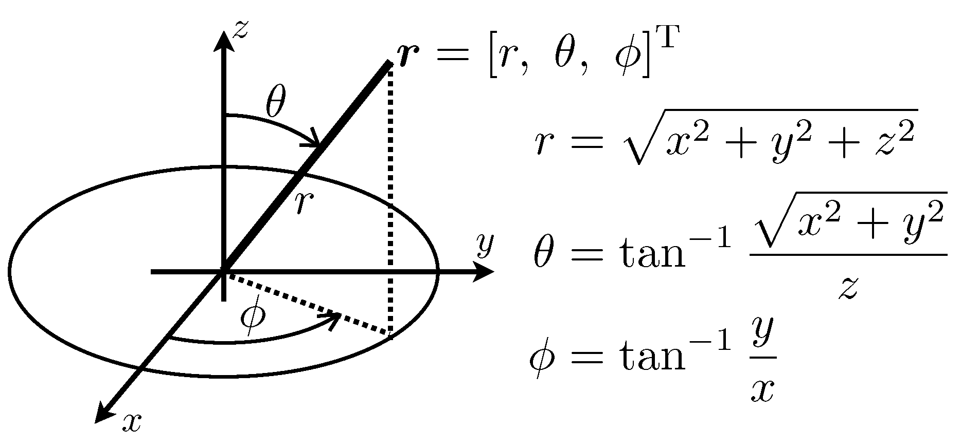
3.1. Cylindrical Harmonic Expansion of Two-Dimensional Sound Field

The cylindrical harmonic expansion of a two-dimensional sound field is briefly introduced here. Spherical coordinates relative to Cartesian coordinates are defined in Figure 3. In two-dimensional sound field, z = 0 and θ = π / 2 .
Its interior expansion in a region, which is homogeneous and free of sources, is given:
P ( r , ϕ , k ) = m = A ˚ m ( k ) J m ( k r ) e j m ϕ ,
where A ˚ m ( k ) and J m are the interior sound field cylindrical harmonic spectrum and the m-th order Bessel function. The corresponding expansion for regions exterior to any sound sources is given:
P ( r , ϕ , k ) = m = B ˚ m ( k ) H m ( k r ) e j m ϕ ,
where B ˚ m ( k ) is the exterior sound field cylindrical harmonic spectrum.

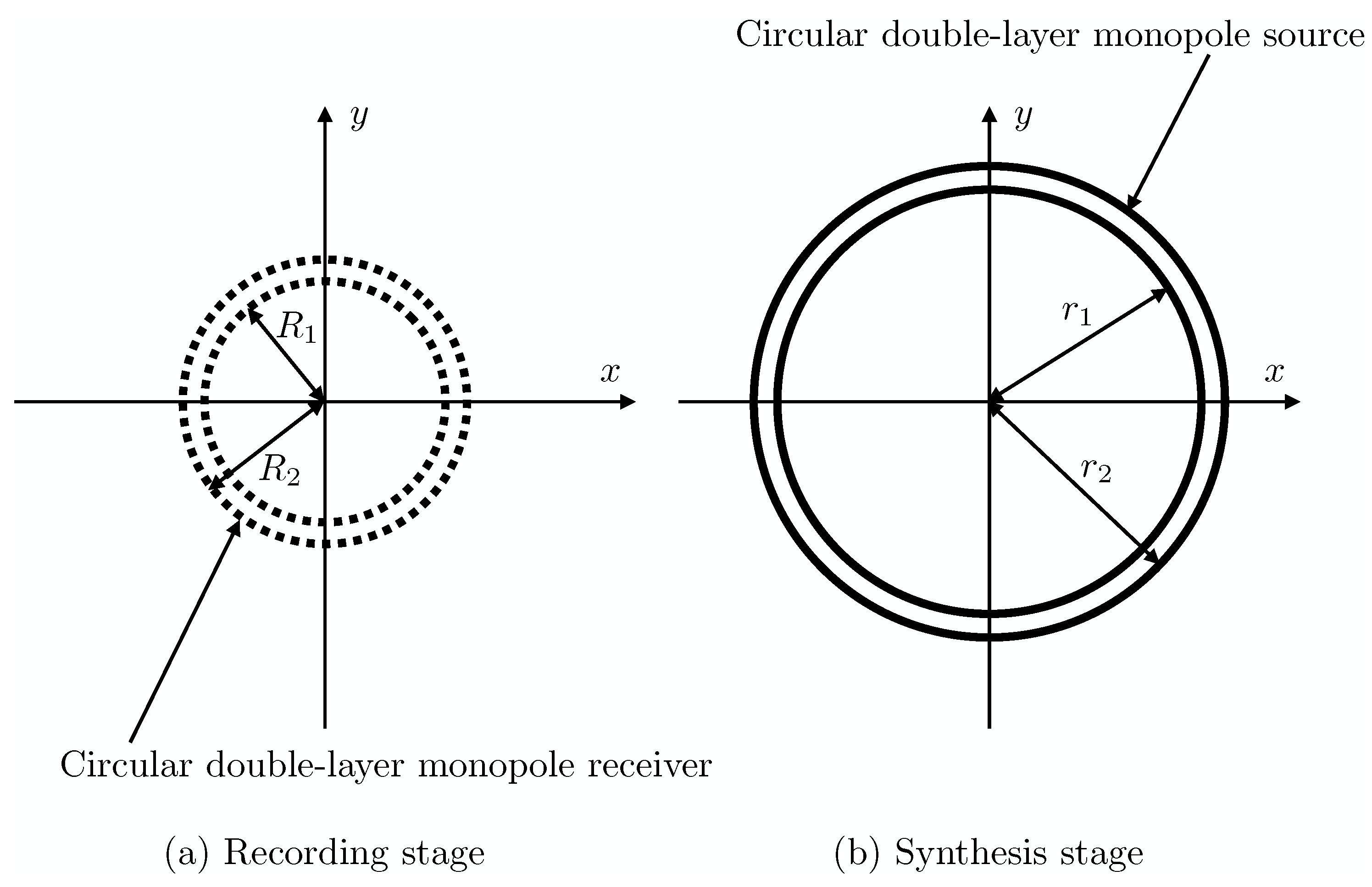
3.2. Interior and Exterior Sound Field Control with Circular Double-Layer Monopole Source and Receiver

A sound field recorded by a continuous circular monopole receiver distribution that is centered at the origin with radius R 0 is converted into the cylindrical harmonic domain [40]:
P ˚ m ( R 0 , k ) = 1 2 π 0 2 π P ( R 0 , ϕ , k ) e j m ϕ d ϕ .
The cylindrical harmonic spectrum of the interior sound field is then obtained:
A ˚ m ( k ) = P ˚ m ( R 0 ) J m ( k R 0 ) .
Equation (15), however, has a forbidden frequency (Bessel-zero) problem where J m ( k R 0 ) = 0 and is dependent on receiver radius R 0 and wavenumber k [40].
To avoid the forbidden frequency problem for open circular monopole receivers, a circular double-layer monopole receiver centered on the origin with radii R 1 and R 2 is introduced (Figure 4a). Sound fields recorded by both layers are converted into the cylindrical harmonic domain by Equation (14) as P ˚ m ( R 1 , k ) and P ˚ m ( R 2 , k ) . By applying a method with spherical double-layer monopole receivers [43] into circular double-layer monopole receivers in the proposed method, the cylindrical harmonic spectrum is calculated:
A ˚ m ( k ) = ( 1 β m ( R 1 , R 2 , k ) ) P ˚ m ( R 1 , k ) + β m ( R 1 , R 2 , k ) P ˚ m ( R 2 , k ) ( 1 β m ( R 1 , R 2 , k ) ) J m ( k R 1 ) + β m ( R 1 , R 2 , k ) J m ( k R 2 ) ,
where
β m ( R 1 , R 2 , k ) = 0 , | J m ( k R 1 ) | | J m ( k R 2 ) | 1 , | J m ( k R 1 ) | < | J m ( k R 2 ) | .
Equation (16) indicates that A ˚ m ( k ) is obtained from a single layer of J m ( k R 1 ) or J m ( k R 2 ) with a large absolute value based on the assumption that J m ( k R 1 ) and J m ( k R 2 ) do not simultaneously become zero. In the proposal, therefore, the absence of mutual zeros needs to hold for all cylindrical harmonic orders.
Alternatively, two methods with circular single-layer receivers have been proposed. The first one introduces an open circular single-layer directional receiver with radius R 0 and the cylindrical harmonic spectrum is obtained [44]:
A ˚ m ( k ) = Q ˚ m ( R 0 ) δ J m ( k R 0 ) j ( 1 δ ) J m ( k R 0 ) ,
where J m is the radial derivative of J m , δ is the dipole weighting factor and Q ˚ m ( R 0 ) is the cylindrical harmonic spectrum of the sound pressure and its radial derivative received by the circular directional receiver with radius R 0 .
The other method employs a circular single-layer receiver mounted on a rigid baffle with radius R 0 , and the cylindrical harmonic spectrum is obtained [45]:
A ˚ m ( k ) = P ˚ m ( R 0 ) J m ( k R 0 ) J m ( k R 0 ) H m ( k R 0 ) H m ( k R 0 ) ,
where H m is the radial derivative of H m . Compared with the method involving double-layer receivers, these methods can be realized using half the number of microphones in actual implementations. However, they cannot be directly compared with the pressure matching-based LS and GSVD methods. To directly compare the proposed mode-matching method with conventional pressure matching-based approaches, a circular double-layer array of microphones is introduced in the computer simulations conducted in the next section.
For simultaneously controlling both the interior and exterior sound fields, a circular double-layer monopole source centered the origin with radii r 1 , and r 2 is introduced (Figure 4b). A sound field produced by the double-layer circular monopole secondary source is then given:
P ( r , ϕ , k ) = 0 2 π D ( r 1 , ϕ 0 , k ) G ( r , r 1 , k ) + D ( r 2 , ϕ 0 , k ) G ( r , r 2 , k ) d ϕ 0 = j 4 0 2 π D ( r 1 , ϕ 0 , k ) H 0 ( k | r r 1 | ) + D ( r 2 , ϕ 0 , k ) H 0 ( k | r r 2 | ) d ϕ 0 ,
where D is the driving function of the secondary sources, r 1 = [ r 1 , ϕ 0 ] T and r 2 = [ r 2 , ϕ 0 ] T .
When the cylindrical harmonic expansion is applied to Equation (20), the circular convolution theorem holds [29] and Equation (20) for interior and exterior fields is represented [34,46]:
(21) P ˚ ( r < , r 1 , k ) = 2 π D ˚ m ( r 1 , k ) G ˚ ( r < , r 1 , k ) + D ˚ m ( r 2 , k ) G ˚ ( r < , r 2 , k ) (22) = 2 π j 4 J m ( k r ) D ˚ m ( r 1 , k ) H m ( k r 1 ) + D ˚ m ( r 2 , k ) H m ( k r 2 ) ,
and
(23) P ˚ ( r > , r 2 , k ) = 2 π D ˚ m ( r 1 , k ) G ˚ ( r > , r 1 , k ) + D ˚ m ( r 2 , k ) G ˚ ( r > , r 2 , k ) (24) = 2 π j 4 H m ( k r ) D ˚ m ( r 1 , k ) J m ( k r 1 ) + D ˚ m ( r 2 , k ) J m ( k r 2 ) ,
where r < , r 1 , 2 and r > , r 1 , 2 denote P ˚ ( r , r 1 , 2 , k ) and G ˚ ( r , r 1 , 2 , k ) for r < r 1 , 2 and r > r 1 , 2 employed in [40] and
G ˚ ( r < , r 1 , 2 , k ) = j 4 J m ( k r ) H m ( k r 1 , 2 ) ,
G ˚ ( r > , r 1 , 2 , k ) = j 4 J m ( k r 1 , 2 ) H m ( k r ) .
To synthesize the interior sound field recorded by the circular double-layer monopole receiver without exterior propagation, P ˚ ( r < , r 1 , k ) and P ˚ ( r > , r 2 , k ) are set to
P ˚ ( r < , r 1 , k ) = A ˚ m ( k ) J m ( k r ) ,
P ˚ ( r > , r 2 , k ) = 0 .
Equations (27) and (28) are then represented in matrix form as in [31,34]:
2 π · j 4 H m ( k r 1 ) H m ( k r 2 ) J m ( k r 1 ) J m ( k r 2 ) D ˚ m ( r 1 , k ) D ˚ m ( r 2 , k ) = A ˚ m ( k ) 0 ,
and the driving function of the circular double-layer monopole source is analytically derived:
D ˚ m ( r 1 , k ) = 2 j J m ( k r 2 ) A ˚ m ( k ) π H m ( k r 1 ) J m ( k r 2 ) H m ( k r 2 ) J m ( k r 1 ) ,
D ˚ m ( r 2 , k ) = 2 j J m ( k r 1 ) A ˚ m ( k ) π H m ( k r 1 ) J m ( k r 2 ) H m ( k r 2 ) J m ( k r 1 ) .
Although the driving signals of the LS and GSVD methods derived in Equations (6) and (11) include the control point locations, those of the proposed method derived in Equations (30) and (31) are independent of the control point locations. The driving signals only depend on estimated cylindrical harmonic spectrum A ˚ m ( k ) and circular source radii r 1 and r 2 since J m ( k r ) and H m ( k r ) are completely cancelled in Equations (30) and (31). Unlike the LS and GSVD methods, the proposed method, therefore, does not require interior and exterior control points.
Continuous circular double-layer receiver and source are finally discretized into circular double-layer arrays of loudspeakers and microphones. When the number of microphones of each layer is I int / 2 with equiangular sampling, the recorded sound fields for radii R 1 and R 2 in the cylindrical harmonic domain are calculated:
P ˚ m ( R 1 , 2 , k ) 2 π I int / 2 · 1 2 π i = 1 I int / 2 P ( R 1 , 2 , ϕ i , k ) e j m ϕ i = 2 I int i = 1 I int / 2 P ( R 1 , 2 , ϕ i , k ) e j m ϕ i .
When the number of loudspeakers of each layer is L / 2 with equiangular sampling, order m of the cylindrical harmonic spectrum in Equations (30) and (31) can be calculated up to M = ( L / 2 1 ) / 2 , where · is the floor function. However, the cylindrical harmonic spectrum at | n | > | k r 1 , 2 | is the evanescent component and is quite large because of the inverse propagation when r > r 1 , 2 [40]. To calculate a stable filter as in [42], m is up to M = | k r 1 , 2 | if | k r 1 , 2 | < ( L / 2 1 ) / 2 since using only the propagation component for | n | | k r 1 , 2 | is sufficient to control the target interior sound field. The driving signal of each loudspeaker at ϕ l for r 1 and r 2 in the frequency domain is obtained:
D ( r 1 , 2 , ϕ l , k ) = m = M M D ˚ m ( r 1 , 2 , k ) e j m ϕ l , l = 1 , 2 , L / 2 .
The purpose of introducing circular double-layer arrays of microphones and loudspeakers in the LS and GSVD methods differs from that in the proposed method. In the LS and GSVD methods, the circular double-layer arrays are introduced to satisfy the KH integral. Hence, an approximated dipole distribution is required. On the other hand, the approximated dipole distribution is not required because the proposed method is not based on the KH integral. Circular double-layer arrays are introduced in the proposed method to avoid the forbidden frequencies in the recording stage and to simultaneously control both the interior and exterior sound field cylindrical harmonic spectrums in the synthesis stage.
In addition, the proposal can also be used when the radii of a circular double-layer array of microphones are larger than those of a circular double-layer array of loudspeakers.
The proposed analytical method can also be easily extended for three-dimensional sound fields by introducing the three-dimensional Green’s function, spherical double-layer arrays and spherical harmonic expansion with the spherical convolution theorem [29] instead of the two-dimensional one in Equation (20), circular arrays shown in Figure 4, and circular harmonic expansion in Equations (12) and (13) with the circular convolution theorem for Equations (21) and (23).

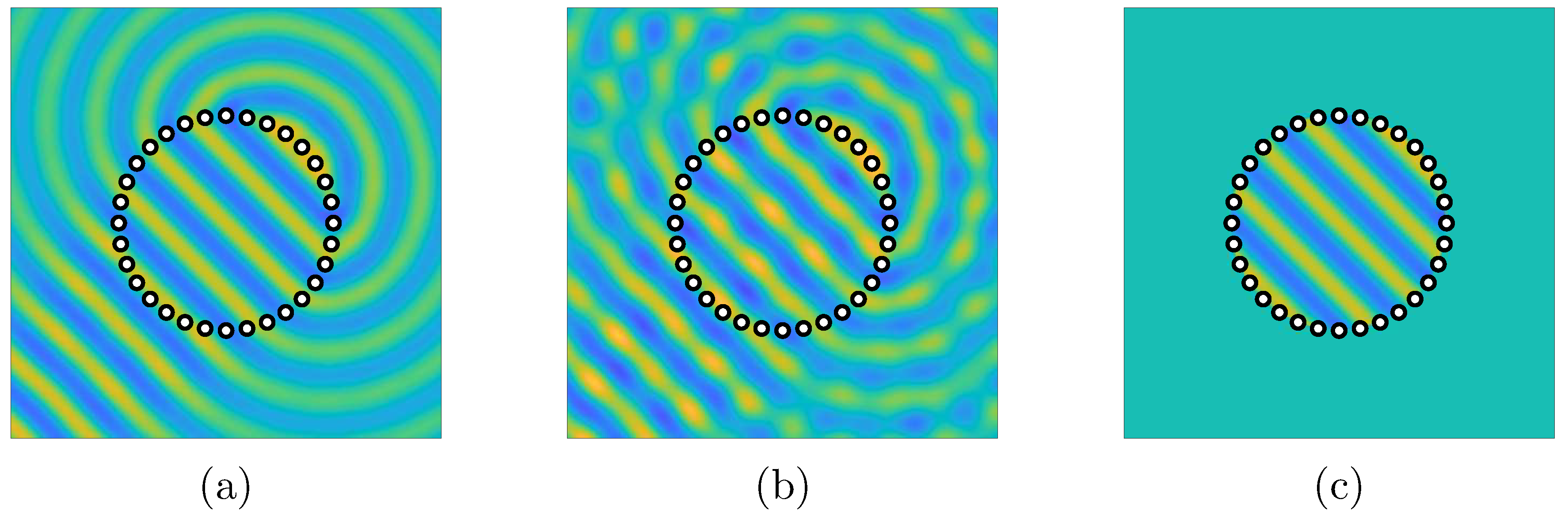
4. Computer Simulations

To evaluate the proposed analytical approach with circular double-layer arrays of microphones and loudspeakers, computer simulations based on the proposed method were performed and compared with the conventional numerical LS and GSVD methods.

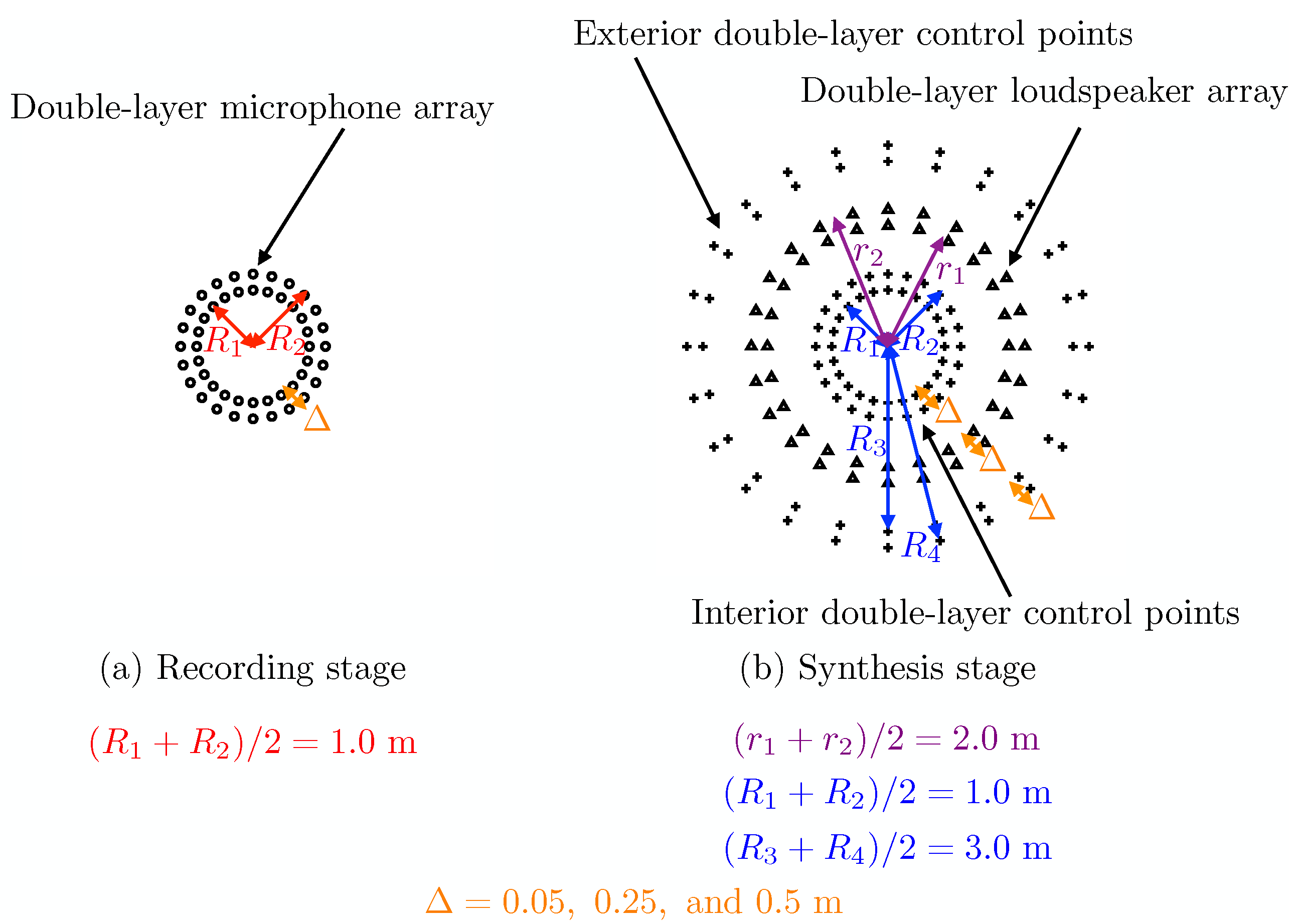
4.1. Simulation Conditions

In all the simulations, two-dimensional sound fields were assumed and both free-field and reverberant conditions were evaluated. The speed of sound c was 343.36 m/s. In the reverberant condition, the two-dimensional room size was 15 m × 12 m and the room center was centered at the origin. The transfer functions in the reverberant condition were calculated by the image method [47] in the frequency domain with reflection coefficient 0.3 and reflection order 10. The primary sound field was calculated as a cylindrical wave propagating in a free-field from a point at x = [ 5 , 3 ] T .
Both the amounts of microphones, interior and exterior control points for the LS and GSVD methods, and loudspeakers for each layer were I int / 2 = L / 2 = 24 , and their total numbers were I int = L = 48 . Then, each layer had 24 elements with equiangular sampling. The central radii of the circular double-layer arrays of microphones and loudspeakers were ( R 1 + R 2 ) / 2 = 1.0 m and ( r 1 + r 2 ) / 2 = 2.0 m. Two circular double-layer arrays of control points with radii R 1 , R 2 , R 3 and R 4 were introduced for the LS and GSVD methods and their central radii were ( R 1 + R 2 ) / 2 = 1.0 m and ( R 3 + R 4 ) / 2 = 3.0 m. Three types of layer intervals Δ = R 2 R 1 = R 4 R 3 = r 2 r 1 = 0.05 , 0.25, and 0.5 m were evaluated. The arrangements of microphones, loudspeakers and control points are illustrated in Figure 5. The case with Δ = 0.05 m is the same condition with previous simulations for the LS and GSVD [38]. The spatial Nyquist frequency of the circular secondary source was approximately derived as [31,39]:
f Nyq c ( L / 2 ) 4 π r 2 .
In the simulations, the f Nyq values were about 324, 309, and 291 Hz for Δ = 0.05 , 0.25, and 0.50 m, respectively.
To evaluate the synthesized sound field, the synthesis error and exterior acoustic contrast at position r were defined as
E ( r ) = 10 log 10 | P org ( r ) P syn ( r ) | 2 | P org ( r ) | 2 ,
C ( r ) = 10 log 10 | P syn ( r ) | 2 | P org ( r ) | 2 ,
where P org ( r ) and P syn ( r ) are, respectively, the primary and synthesized sound pressures at position r . To evaluate the interior sound field synthesis accuracy and exterior acoustic contrast, the spatially-averaged synthesis error within r 1.5 m and exterior acoustic contrast with 2.5 m r 4.5 m were, respectively, calculated for 10 Hz f 500 Hz.
In the GSVD method, singular value truncation parameter K in Equation (11) was also automatically chosen to satisfy that all the diagonal terms of C K ( k ) are smaller than 0.01 [39]. The maximum cylindrical harmonic order was M = ( L / 2 1 ) / 2 = 11 in the proposed approach.

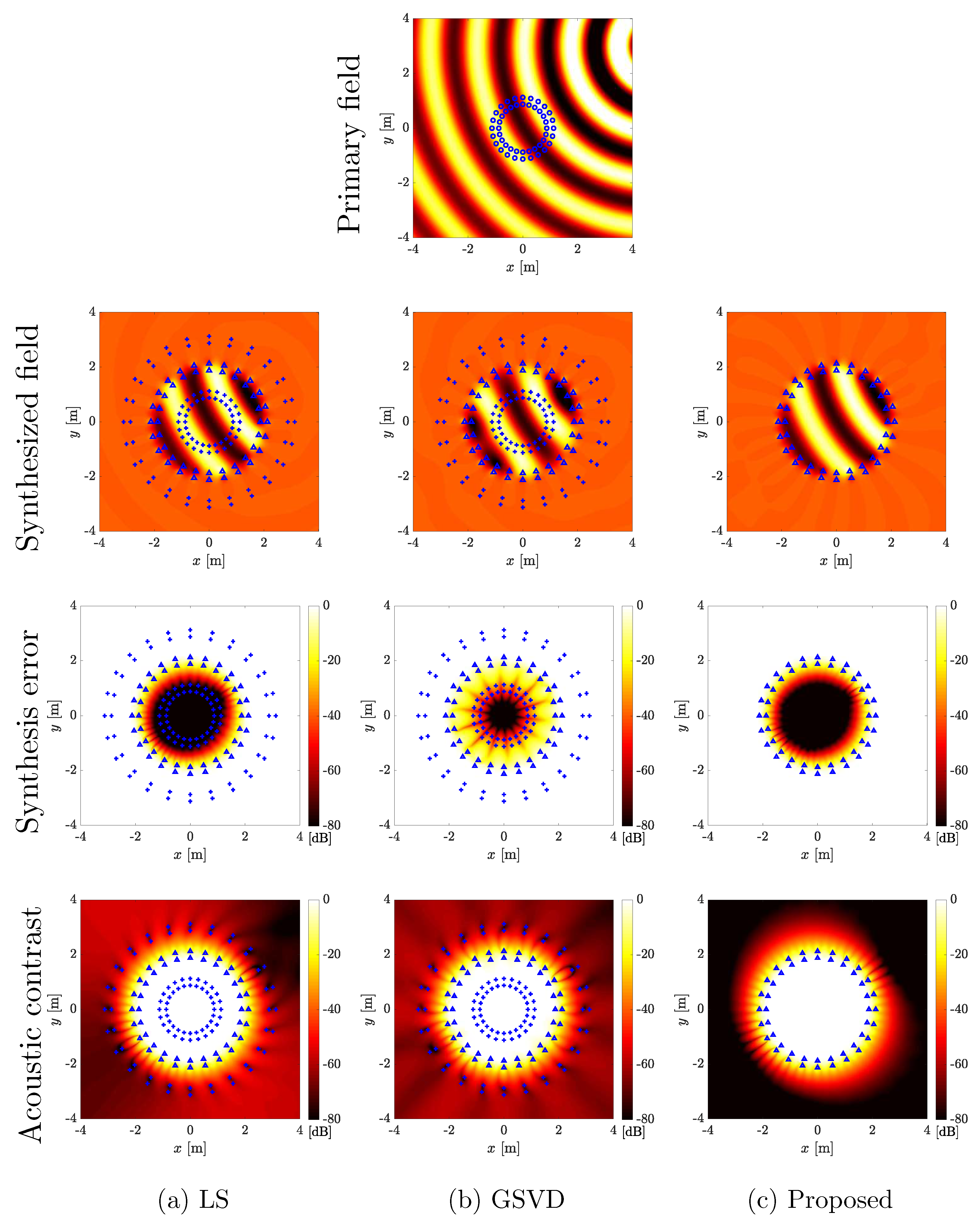
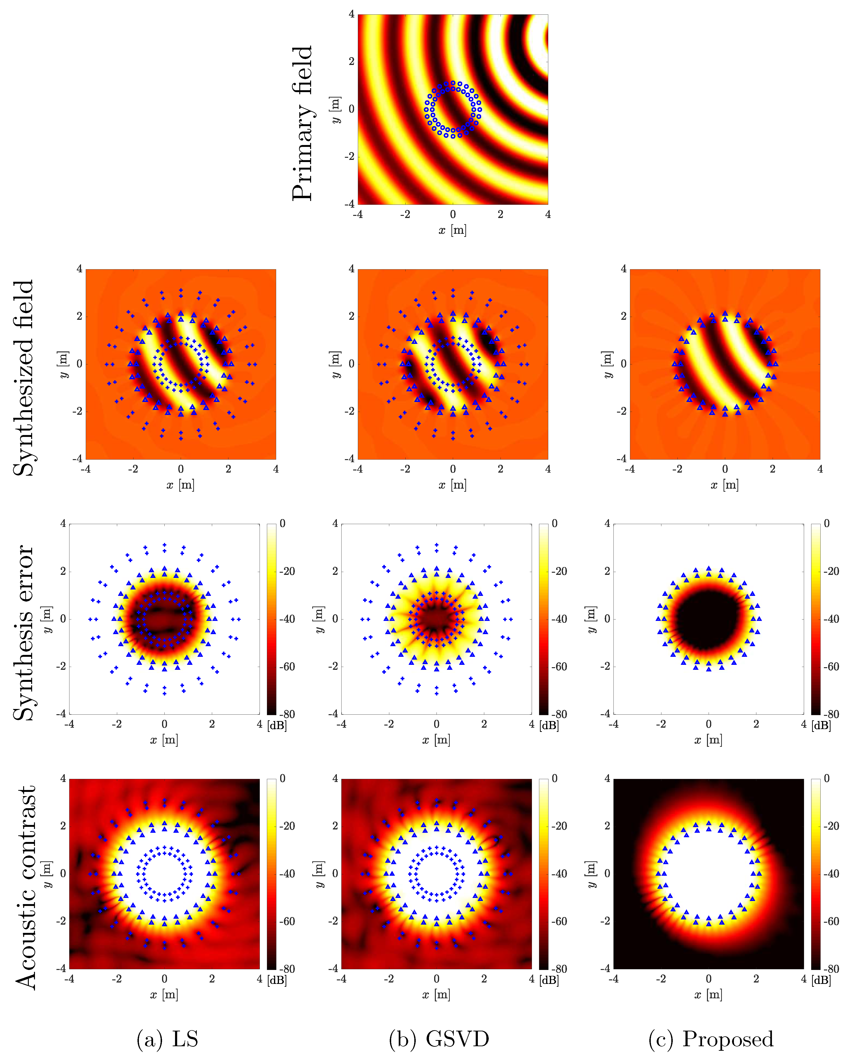
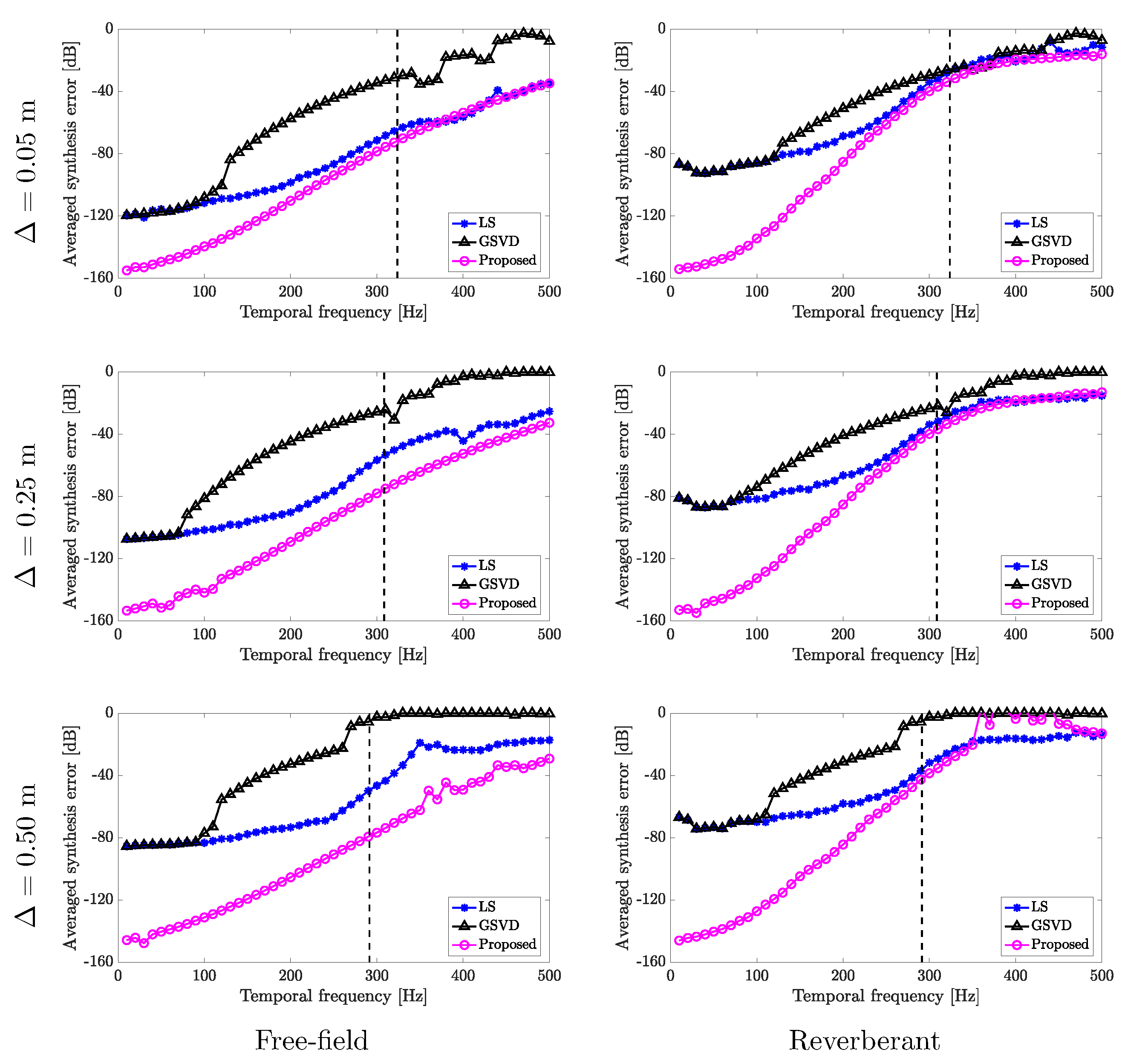
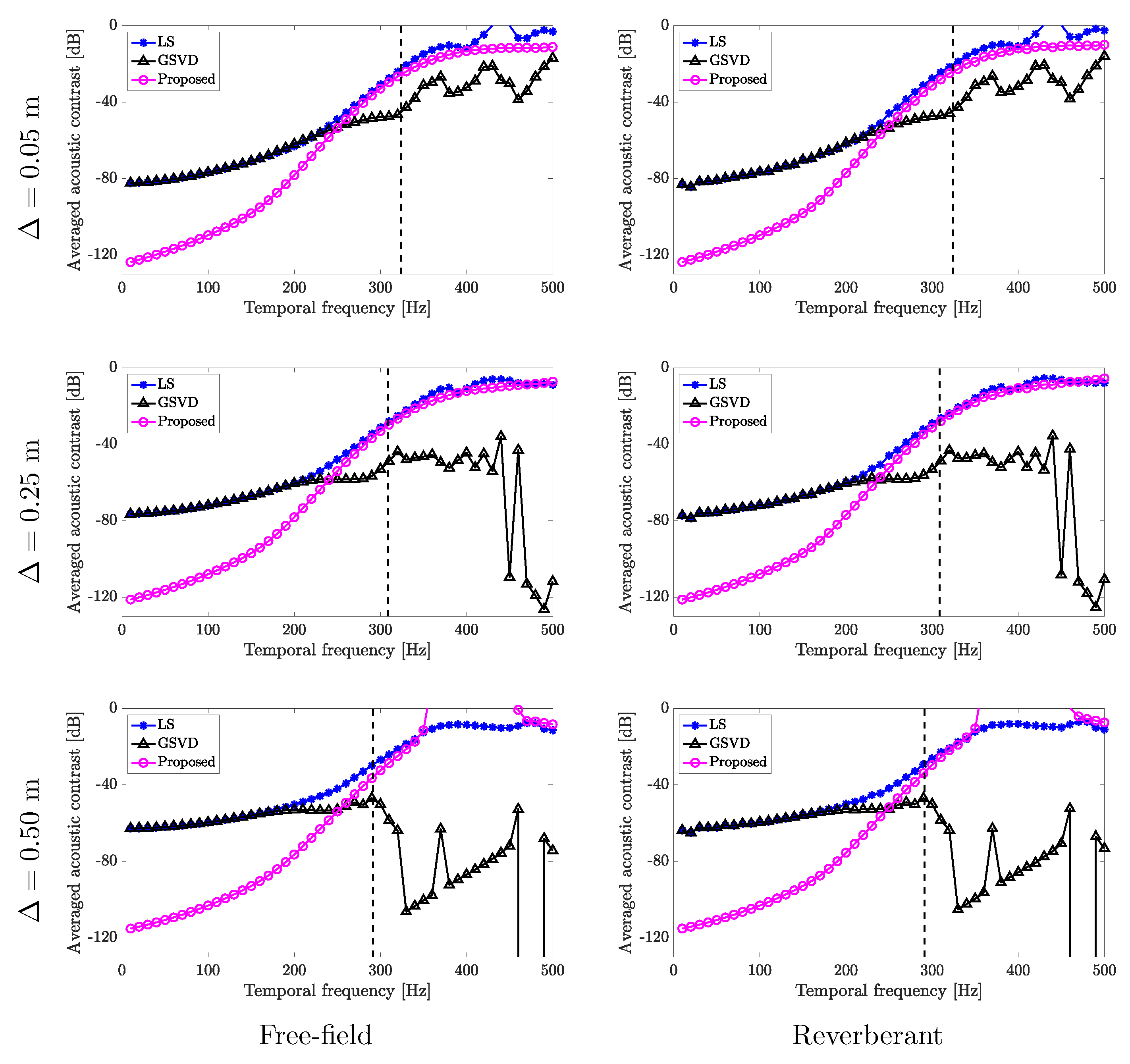
4.2. Interior Synthesis Accuracy and Exterior Acoustic Contrast

Figure 6 and Figure 7, respectively, show the results of the primary sound field, synthesized sound field, interior sound field synthesis accuracy, and exterior acoustic contrast by the LS, GSVD, and proposed mode-matching methods with Δ = 0.25 m in both the free-field and reverberant conditions for f = 200 . The results in Figure 6 indicate that the LS and proposed methods realize a higher interior control accuracy than the GSVD method. This is because the conventional GSVD method reduces the exterior propagation above the spatial Nyquist frequency at the expense of the interior synthesis accuracy [39]. The results in Figure 6 also suggest that the proposed method can achieve the highest exterior acoustic contrast. As a result, the interior synthesis accuracies of the LS and GSVD methods are degraded by the reverberations caused by exterior propagations (Figure 7). On the other hand, only the proposed method can successfully control both the interior and exterior sound fields in the reverberant condition (Figure 7).
Figure 8 and Figure 9, respectively, plot the results of the spatially-averaged interior synthesis error and exterior acoustic contrast defined in Equations (35) and (36).
As described above, the conventional GSVD approach reduces the exterior propagation beyond the spatial Nyquist frequency at the expense of the interior synthesis accuracy [39]. The results in Figure 9 show that the GSVD method successfully reduces the exterior propagation over the spatial Nyquist frequency compared with the LS and proposed methods. However, the interior field is no longer synthesized by the GSVD method at higher frequencies (Figure 8).
The results in Figure 6, Figure 7, Figure 8 and Figure 9 demonstrate the main impact of this paper; compared to conventional numerical approaches, the proposed method can more accurately synthesize the interior field while reducing the exterior propagation below the spatial Nyquist frequency in both the free-field and reverberant conditions. As described above, this is because the proposed method realizes the highest exterior acoustic contrast and successfully controls both the interior and exterior sound fields in the reverberant condition. These results also suggest the effectiveness of the spatial Fourier transform-based approach compared with the LS method [14,34,41,42].
Unlike the LS and GSVD methods, which depend on layer intervals Δ , the proposed method’s interior field synthesis accuracy is independent of Δ (Figure 8) because the proposed method can successfully estimate the interior sound field cylindrical harmonic spectrum from the circular double-layer microphone array using Equation (16) without the forbidden frequencies. The proposed method does not control the discretized sound pressures. Instead, it controls the estimated sound field in the cylindrical harmonic domain, as derived in Equations (30) and (31). However, the driving signals of the LS and GSVD methods obviously include the control point and loudspeaker locations, as described in Equations (6) and (11).

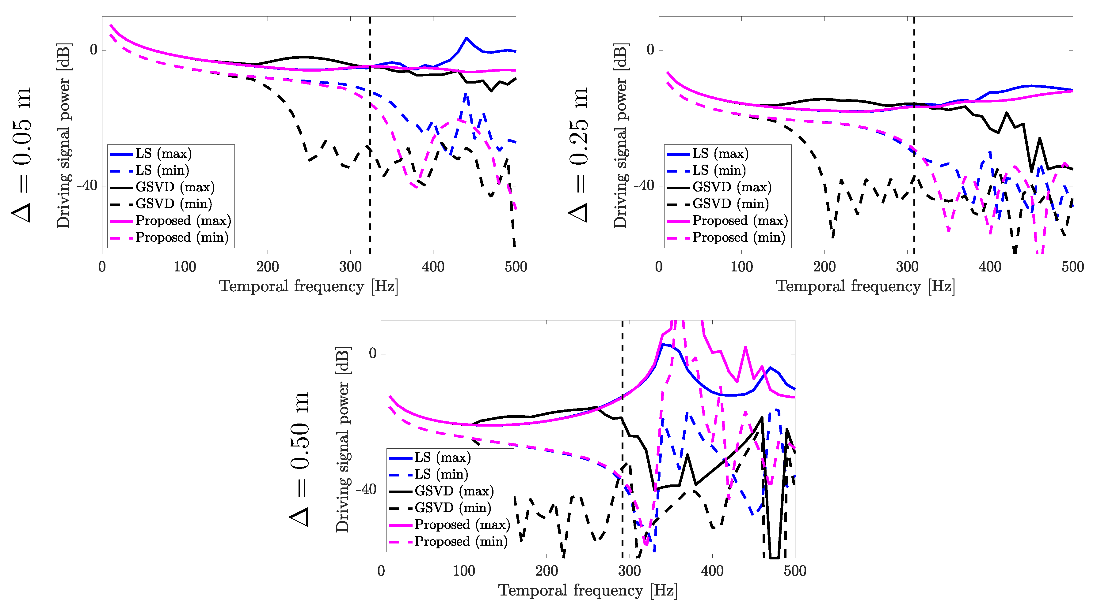
4.3. Driving Signal Stability

To evaluate the driving signal stability, Figure 10 plots maximum and minimum driving signal powers 10 log 10 max ( | D ( r 1 , 2 , ϕ l ) | 2 ) and 10 log 10 min ( | D ( r 1 , 2 , ϕ l ) | 2 ) . The driving signals of the proposed method for all the layer intervals below the spatial Nyquist frequency are stable, similar to those of the LS method. These results suggest that the forbidden frequencies for J m ( k r 1 ) , J m ( k r 2 ) , J m ( k R 1 ) and J m ( k R 2 ) in Equations (16), (30) and (31) were effectively avoided by the proposed method in these array configurations.
The driving signal dynamic ranges of the GSVD method for all layer intervals were larger than the others, although the driving signal stability was not evaluated in a previous work [38].

4.4. Limitations

The proposed method has two limitations. One is that it cannot control the exterior field above the spatial Nyquist frequency because it is based on the spatial Fourier transformation in cylindrical coordinates [40] (Figure 9). The other is that circular and spherical double-layer array configurations with equiangular sampling are required for the proposed method to derive analytical formulations. In contrast, the conventional LS and GSVD methods can manage other configurations such as the rectangular and quadrate double-layer array employed in [39].
Consequently, the effectiveness of the proposed analytical approach using circular double-layer arrays of microphones and loudspeakers was confirmed in terms of its interior sound field synthesis accuracy and exterior propagation reduction within the spatial Nyquist frequency compared with the conventional numerical LS and GSVD methods in both the free-field and reverberant conditions.

5. Conclusions

This study proposed a sound field control approach to recording a primary sound field and synthesizing it at a secondary field without exterior radiation using circular double-layer arrays of microphones and loudspeakers. Although the conventional LS and GSVD methods are based on a numerical approach and control the discretized sound pressures at the interior and exterior control points, a mode-matching-based analytical method with circular double-layer receiver and source was proposed. The primary sound field cylindrical harmonic spectrum was analytically obtained from the recorded sound pressures without forbidden frequencies, and the driving signals of the loudspeakers for synthesizing it were analytically derived without interior and exterior control points. The proposed analytical approach’s better effectiveness with circular double-layer arrays of microphones and loudspeakers was confirmed by computer simulations in terms of the interior sound field synthesis accuracy and exterior propagation reduction within the spatial Nyquist frequency compared with the conventional numerical LS and GSVD methods in both the free-field and reverberant conditions. The proposal can also be easily extended for three-dimensional sound fields by introducing the three-dimensional Green’s function, spherical double-layer arrays, and spherical harmonic expansion.

Funding

This study was partly supported by JSPS KAKENHI Grant Numbers JP15K21674 and JP18K11387.

Conflicts of Interest

The author declare no conflict of interest.

References

  1. Choi, J.W.; Kim, Y.H. Generation of an acoustically bright zone with an illuminated region using multiple sources. J. Acoust. Soc. Am. 2002, 111, 1695–1700. [Google Scholar] [CrossRef] [PubMed]
  2. Jones, M.; Elliot, S.J. Personal audio with multiple dark zones. J. Acoust. Soc. Am. 2008, 124, 3497–3506. [Google Scholar] [CrossRef] [PubMed] [Green Version]
  3. Chang, J.H.; Lee, C.H.; Park, J.Y.; Kim, Y.H. A realization of sound focused personal audio system using acoustic contrast control. J. Acoust. Soc. Am. 2009, 125, 2091–2097. [Google Scholar] [CrossRef] [PubMed]
  4. Elliot, S.J.; Cheer, J.; Murfet, H.; Holland, K.R. Minimally radiating sources for personal audio. J. Acoust. Soc. Am. 2010, 128, 1721–1728. [Google Scholar] [CrossRef] [PubMed]
  5. Shin, M.; Lee, S.Q.; Fazi, F.M.; Nelson, P.A.; Kim, D.; Wang, S.; Park, K.H.; Seo, J. Maximization of acoustic energy difference between two spaces. J. Acoust. Soc. Am. 2010, 128, 121–131. [Google Scholar] [CrossRef] [PubMed]
  6. Elliott, S.J.; Cheer, J.; Choi, J.W.; Kim, Y. Robustness and regularization of personal audio systems. IEEE Trans. Audio Speech Lang. Process. 2012, 20, 2123–2133. [Google Scholar] [CrossRef]
  7. Coleman, P.; Jackson, P.J.B.; Olik, M.; Møller, M.; Olsen, M.; Pedersen, J.A. Acoustic contrast, planarity and robustness of sound zone methods using a circular loudspeaker array. J. Acoust. Soc. Am. 2014, 135, 1929–1940. [Google Scholar] [CrossRef] [PubMed] [Green Version]
  8. Cai, Y.; Wu, M.; Yang, J. Sound reproduction in personal audio systems using the least-squares approach with acoustic contrast control constraint. J. Acoust. Soc. Am. 2014, 135, 734–741. [Google Scholar] [CrossRef] [PubMed]
  9. Shin, M.; Fazi, F.M.; Nelson, P.A.; Hirono, F.C. Controlled sound field with a dual layer loudspeaker array. J. Sound Vib. 2014, 333, 3794–3817. [Google Scholar] [CrossRef]
  10. Helwani, K.; Spors, S.; Buchner, H. The synthesis of sound figures. Multidimens. Syst. Signal Process. 2014, 25, 379–403. [Google Scholar] [CrossRef]
  11. Coleman, P.; Jackson, P.J.B.; Olik, M.; Pedersen, J.A. Personal audio with a planar bright zone. J. Acoust. Soc. Am. 2014, 136, 1725–1735. [Google Scholar] [CrossRef] [PubMed] [Green Version]
  12. Olik, M.; Jackson, P.J.B.; Coleman, P. Optimal source placement for sound zone reproduction with first order reflections. J. Acoust. Soc. Am. 2014, 136, 3085–3096. [Google Scholar] [CrossRef] [PubMed] [Green Version]
  13. Gálvez, M.F.S.; Elliott, S.J.; Cheer, J. Time domain optimization of filters used in a loudspeaker array for personal audio. IEEE/ACM Trans. Audio Speech Lang. Process. 2015, 23, 1869–1878. [Google Scholar] [CrossRef]
  14. Okamoto, T.; Sakaguchi, A. Experimental validation of spatial Fourier transform-based multiple sound zone generation with a linear loudspeaker array. J. Acoust. Soc. Am. 2017, 141, 1769–1780. [Google Scholar] [CrossRef] [PubMed] [Green Version]
  15. Olivieri, F.; Fazi, F.M.; Fontana, S.; Menzies, D.; Nelson, P.A. Generation of private sound with a circular loudspeaker array and the weighted pressure matching method. IEEE/ACM Trans. Audio Speech Lang. Process. 2017, 25, 1579–1591. [Google Scholar] [CrossRef]
  16. Wu, Y.J.; Abhayapala, T.D. Spatial multizone soundfield reproduction: Theory and design. IEEE Trans. Audio Speech Lang. Process. 2011, 19, 1711–1720. [Google Scholar] [CrossRef]
  17. Radmanesh, N.; Burnett, I.S. Generation of isolated wideband sound fields using a combined two-stage Lasso-LS algorithm. IEEE Trans. Audio Speech Lang. Process. 2013, 21, 378–387. [Google Scholar] [CrossRef]
  18. Poletti, M.A.; Fazi, F.M. An approach to generating two zones of silence with application to personal sound systems. J. Acoust. Soc. Am. 2015, 137, 598–605. [Google Scholar] [CrossRef] [PubMed] [Green Version]
  19. Betlehem, T.; Zhang, W.; Poletti, M.; Abhayapala, T. Personal sound zones: Delivering interface-free audio to multiple listeners. IEEE Signal Process. Mag. 2015, 32, 81–91. [Google Scholar] [CrossRef]
  20. Jin, W.; Kleijn, W.B. Theory and design of multizone soundfield reproduction using sparse methods. IEEE/ACM Trans. Audio Speech Lang. Process. 2015, 23, 2343–2355. [Google Scholar]
  21. Radmanesh, N.; Burnett, I.S.; Rao, B.D. A Lasso-LS optimization with a frequency variable dictionary in a multizone sound system. IEEE/ACM Trans. Audio Speech Lang. Process. 2016, 24, 583–593. [Google Scholar] [CrossRef]
  22. Poletti, M.A.; Fazi, F.M. Generation of half-space sound fields with application to personal sound systems. J. Acoust. Soc. Am. 2016, 139, 1294–1302. [Google Scholar] [CrossRef] [PubMed] [Green Version]
  23. Zhang, W.; Abhayapala, T.D.; Betlehem, T.; Fazi, F.M. Analysis and control of multi-zone sound field reproduction using modal-domain approach. J. Acoust. Soc. Am. 2016, 140, 2134–2144. [Google Scholar] [CrossRef] [PubMed] [Green Version]
  24. Buerger, M.; Hofmann, C.; Kellermann, W. Broadband multizone sound rendering by jointly optimizing the sound pressure and particle velocity. J. Acoust. Soc. Am. 2018, 143, 1477–1490. [Google Scholar] [CrossRef] [PubMed] [Green Version]
  25. Donley, J.; Ritz, C.H.; Kleijn, W.B. Multizone soundfield reproduction with privacy and quality based speech masking filters. IEEE/ACM Trans. Audio Speech Lang. Process. 2018, 26, 1041–1055. [Google Scholar] [CrossRef]
  26. Berkhout, A.J.; de Vries, D.; Vogel, P. Acoustic control by wave field synthesis. J. Acoust. Soc. Am. 1993, 93, 2764–2778. [Google Scholar] [CrossRef]
  27. Spors, S.; Rabenstein, R.; Ahrens, J. The theory of wave field synthesis revisited. In Proceedings of the 124th Audio Engineering Society Convention 2008, Amsterdam, The Netherlands, 17–20 May 2008. [Google Scholar]
  28. Poletti, M.A. Three-dimensional surround sound systems based on spherical harmonics. J. Audio Eng. Soc. 2005, 53, 1004–1025. [Google Scholar]
  29. Ahrens, J.; Spors, S. An analytical approach to sound field reproduction using circular and spherical loudspeaker distributions. Acta Acust. Acust. 2008, 94, 988–999. [Google Scholar] [CrossRef]
  30. Ahrens, J.; Spors, S. Sound field reproduction using planar and linear arrays of loudspeakers. IEEE Trans. Audio Speech Lang. Process. 2010, 18, 2038–2050. [Google Scholar] [CrossRef]
  31. Poletti, M.A.; Abhayapala, T.D. Interior and exterior sound field control using general two-dimensional first-order sources. J. Acoust. Soc. Am. 2011, 129, 234–244. [Google Scholar] [CrossRef] [PubMed]
  32. Poletti, M.A.; Abhayapala, T.D.; Samarasinghe, P. Interior and exterior sound field control using two dimensional higher-order variable-directivity sources. J. Acoust. Soc. Am. 2012, 131, 3814–3823. [Google Scholar] [CrossRef] [PubMed]
  33. Chang, J.H.; Jacobsen, F. Sound field control with a circular double-layer array of loudspeaker. J. Acoust. Soc. Am. 2012, 131, 4518–4525. [Google Scholar] [CrossRef] [PubMed]
  34. Okamoto, T. Analytical approach to 2.5D sound field control using a circular double-layer array of fixed-directivity loudspeakers. In Proceedings of the 42nd IEEE International Conference on Acoustics, Speech and Signal ICASSP 2017, New Orleans, LA, USA, 5–9 May 2017; pp. 91–95. [Google Scholar]
  35. Zhang, W.; Samarasinghe, P.N.; Chen, H.; Abhayapala, T.D. Surround by sound: A review of spatial audio recording and reproduction. Appl. Sci. 2017, 7, 532. [Google Scholar] [CrossRef]
  36. Kirkeby, O.; Nelson, P. Reproduction of plane wave sound fields. J. Acoust. Soc. Am. 1993, 94, 2992–3000. [Google Scholar] [CrossRef]
  37. Betlehem, T.; Abhayapala, T.D. Theory and design of sound field reproduction in reverberant rooms. J. Acoust. Soc. Am. 2005, 117, 2100–2111. [Google Scholar] [CrossRef] [PubMed]
  38. Bai, Z.; Demmel, J.W. Computing the generalized singular value decomposition. SIAM J. Sci. Comput. 1993, 14, 1464–1486. [Google Scholar] [CrossRef]
  39. Pasco, Y.; Gauthier, P.A.; Berry, A.; Moreau, S. Interior sound field control using generalized singular value decomposition in the frequency domain. J. Acoust. Soc. Am. 2017, 141, 334–345. [Google Scholar] [CrossRef] [PubMed]
  40. Williams, E.G. Fourier Acoustics: Sound Radiation and Nearfield Acoustic Holography; Academic Press: London, UK, 1999. [Google Scholar]
  41. Okamoto, T. Generation of multiple sound zones by spatial filtering in wavenumber domain using a linear array of loudspeakers. In Proceedings of the IEEE International Conference on Acoustics, Speech and Signal Processing ICASSP 2014, Florence, Italy, 4–9 May 2014; pp. 4733–4737. [Google Scholar]
  42. Okamoto, T. Analytical methods of generating multiple sound zones for open and baffled circular loudspeaker arrays. In Proceedings of the IEEE Workshop on Applications of Signal Processing to Audio and Acoustics WASPAA 2015, New Paltz, NY, USA, 18–21 October 2015. [Google Scholar]
  43. Balmages, I.; Rafaely, B. Open-sphere designs for spherical microphone arrays. IEEE Trans. Audio Speech Lang. Process. 2007, 15, 727–732. [Google Scholar] [CrossRef]
  44. Poletti, M.A. A unified theory of horizontal holographic sound systems. J. Audio Eng. Soc. 2000, 48, 1155–1182. [Google Scholar]
  45. Tiana-Roig, E.; Jacobsen, F.; Grande, E.F. Beamforming with a circular microphone array for localization of environmental noise sources. J. Acoust. Soc. Am. 2010, 128, 3535–3542. [Google Scholar] [CrossRef] [PubMed]
  46. Fahim, A.; Samarasinghe, P.; Abhayapala, T.D. Extraction of exterior field from a mixed sound field for 2D height-invariant sound propagation. In Proceedings of the 2016 IEEE International Workshop on Acoustic Signal Enhancement (IWAENC), Xi’an, China, 13–16 September 2016. [Google Scholar]
  47. Allen, J.B.; Berkley, D.A. Image method for efficiently simulating small-room acoustics. J. Acoust. Soc. Am. 1979, 65, 943–950. [Google Scholar] [CrossRef]
Figure 1. Comparison of two-dimensional sound field syntheses with a circular array: (a) typical interior sound field synthesis in a free-field; (b) typical interior sound field synthesis in a reverberant environment; and (c) undesired propagation-free sound field synthesis in a reverberant environment.
Applsci 08 01084 g001
Figure 2. Arrangements: (a) double-layer microphone array for recording a primary sound field; and (b) double-layer arrays of loudspeakers and control points for synthesizing recorded primary sound field at a secondary field.
Applsci 08 01084 g002
Figure 3. Definition of spherical coordinates relative to Cartesian coordinates.
Applsci 08 01084 g003
Figure 4. Arrangements: (a) circular double-layer monopole receiver for recording a primary sound field; and (b) circular double-layer monopole source for synthesizing recorded primary sound field at a secondary field.
Applsci 08 01084 g004
Figure 5. Computer simulations conditions: (a) double-layer microphone array; and (b) double-layer arrays of loudspeakers and control points. Each layer has 24 elements with equiangular sampling.
Applsci 08 01084 g005
Figure 6. Results of primary sound field, synthesized sound field, interior sound field synthesis accuracy and exterior acoustic contrast by LS, GSDV, and proposed mode-matching methods with Δ = 0.25 m in free-field condition for f = 200 Hz. Blue ∘, △ and + are microphones, loudspeakers and control points, respectively.
Applsci 08 01084 g006
Figure 7. Results of primary sound field, synthesized sound field, interior sound field synthesis accuracy and exterior acoustic contrast by LS, GSDV, and proposed mode-matching methods with Δ = 0.25 m in reverberant condition for f = 200 Hz. Blue ∘, △ and + are microphones, loudspeakers and control points, respectively.
Applsci 08 01084 g007
Figure 8. Results of spatially-averaged synthesis error for interior sound field within r 1.5 m.
Applsci 08 01084 g008
Figure 9. Results of spatially-averaged acoustic contrast for exterior sound field with 2.5 m r 4.5 m.
Applsci 08 01084 g009
Figure 10. Results of maximum and minimum driving signal power.
Applsci 08 01084 g010

