Fabrication and Testing of Thermoelectric CMOS-MEMS Microgenerators with CNCs Film

1
Department of Mechanical Engineering, National Chung Hsing University, Taichung 402, Taiwan
2
Department of Mechanical and Electro-Mechanical Engineering, Tamkang University, Tamsui 251, Taiwan
3
Department of Electro-Optical Engineering, Yuan Ze University, Taoyuan 320, Taiwan
*
Author to whom correspondence should be addressed.
Appl. Sci. 2018, 8(7), 1047; https://doi.org/10.3390/app8071047
Submission received: 27 May 2018
/
Revised: 20 June 2018
/
Accepted: 25 June 2018
/
Published: 27 June 2018
(This article belongs to the Special Issue Selected Papers from the 2017 International Conference on Inventions)
Abstract
:Featured Application
The thermoelectric microgenerators converted waste heat to electrical power and thus have a potential for application in electronic devices and microsensors.
Abstract
Manufacturing and testing of a TMG (thermoelectric microgenerator) with CNCs (carbon nanocapsules) film fabricated utilizing a CMOS (complementary metal oxide semiconductor) technology are investigated. The microgenerator includes a CNCs layer, thermopiles, and thermometers. CNCs, a heat absorbing material, are coated on the microgenerator, so that the TD (temperature difference) of HP (hot part) and CP (cold part) in the thermopiles increases, resulting in an enhancement of the microgenerator OP (output power). Thermometers fabricated in the microgenerator are employed to detect the HP and CP temperature in thermopiles. In order to enhance thermopiles’ TD, the HP in thermopiles was manufactured as suspension structures isolating heat dissipation, and the CP in thermopiles was made on a silicon substrate to increase the heat sink. Experiments showed that the microgenerator OV (output voltage) was 3.3 mV and its output power was 125 pW at TD 3 K. Voltage and power factors of TMG were 0.71 mV/K/mm2 and 9.04 pW/K2/mm2, respectively.
1. Introduction
A rapidly growing population results in the consumption of a large amount of energy. Nowadays, fossil fuels are the main energy source in the world. Unfortunately, fossil fuels increase exhausts, which cause air pollution and the greenhouse effect. After most of the energy is used, it is transformed into waste heat, and then dissipated ambiently. If waste heat can be converted to electrical power, it will provide more energy and reduce carbon emissions.
Micro-electro-mechanical-system (MEMS) techniques have been applied in the manufacturing of microactuators and microdevices [1,2,3,4,5]. Recently, micro thermoelectric generators were developed using MEMS technology. For instance, Zhang et al. [6] manufactured TMG using micromachining and electroplating. Materials of thermopiles in the microgenerator were bismuth telluride and antimony telluride because they had a high thermoelectric coefficient. Bismuth telluride and antimony telluride that were n-type and p-type semiconductors, respectively, were deposited on a polymer substrate. Thereby, the microgenerator had a flexible property, and its power density was 9.2 mW/cm2 at TD 52 K. Yuan [7] proposed planar TMG with an excellent thermal property. The structure of TMG contained polysilicon-based thermopiles and a membrane, which were fabricated by periodically etching silicon substrates. Perez-Marin et al. [8] fabricated a TMG on a silicon substrate utilizing a CMOS process. The structure of the thermogenerator consisted of a single-crystalline silicon membrane that was 100 nm thick with n- and p-type doped thermopiles. This device had an OP density of 4.5 μW/cm2 at TD 5 K. Kouma [9] utilized micromachining to make the TMG. Thermopiles of the generator had a high aspect ratio structure. The microgenerator had an OV factor of 0.16 V/K/cm2 and an OP factor of 9.3 μW/K2/cm2. Feng et al. [10] manufactured a thermoelectric microgenerator on a glass substrate using a single Sb doped ZnO microwire. The microgenerator had a maximum OV of 68 mV at TD 20 K. Yamamuro [11] made flexible thin-film thermoelectric generators utilizing electroplating. Thermopiles were constructed by n-type bismuth telluride and p-type antimony telluride, which were deposited on a flexible substrate using electroplating, followed by a transfer process. The flexible TMG power was 10.4 nW under TD 60 K. Hashimoto [12] developed a silicon nanowire TMG. The thermoelectric generator was made on a silicon substrate utilizing micromachining, and the surface of the generator was covered with silicon dioxide layers.
Many MEMS components manufactured utilizing CMOS technology are called CMOS-MEMS devices [13,14,15,16]. Fabrication of these devices is compatible with the IC (integrated circuit) process, so that they are able to integrate with IC on a chip [17,18,19,20,21]. In this study, we make a COMS-MEMS thermoelectric microgenerator with a CNCs film. The microgenerator is a kind of CMOS-MEMS device, and it has potential for integration with IC for application in electronic devices and sensors. In order to enhance heat absorption at HP in thermopiles, CNCs are deposited on the surface in the microgenerator. The HP in the thermopiles is a suspension structure isolating heat dissipation, and the CP in thermopiles is anchored on the substrate increasing the heat sink, leading to enhancement of the TD in thermopiles.
2. Design of Microgenerator
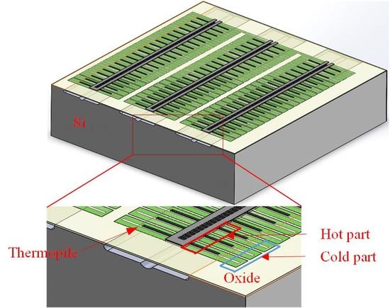
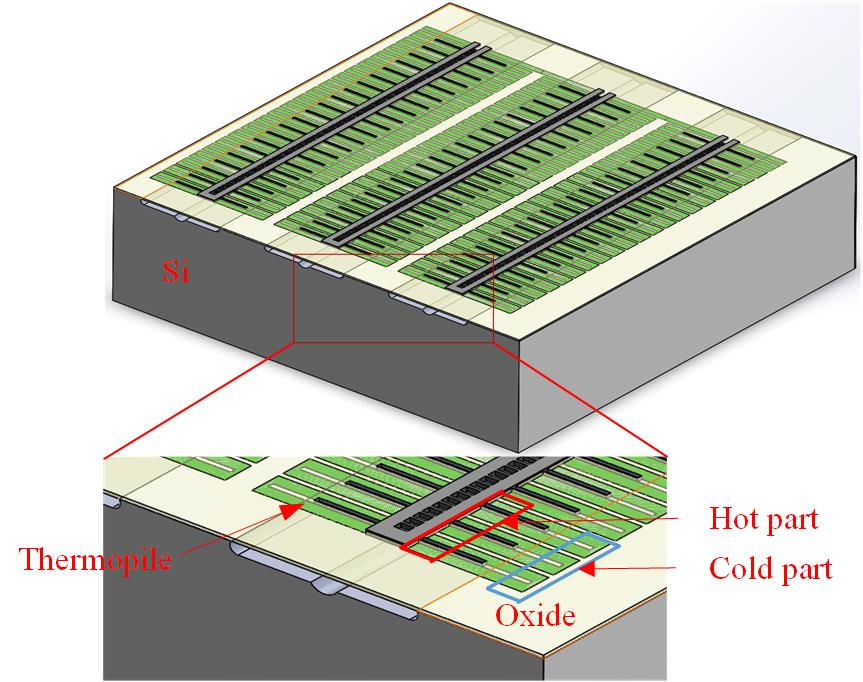
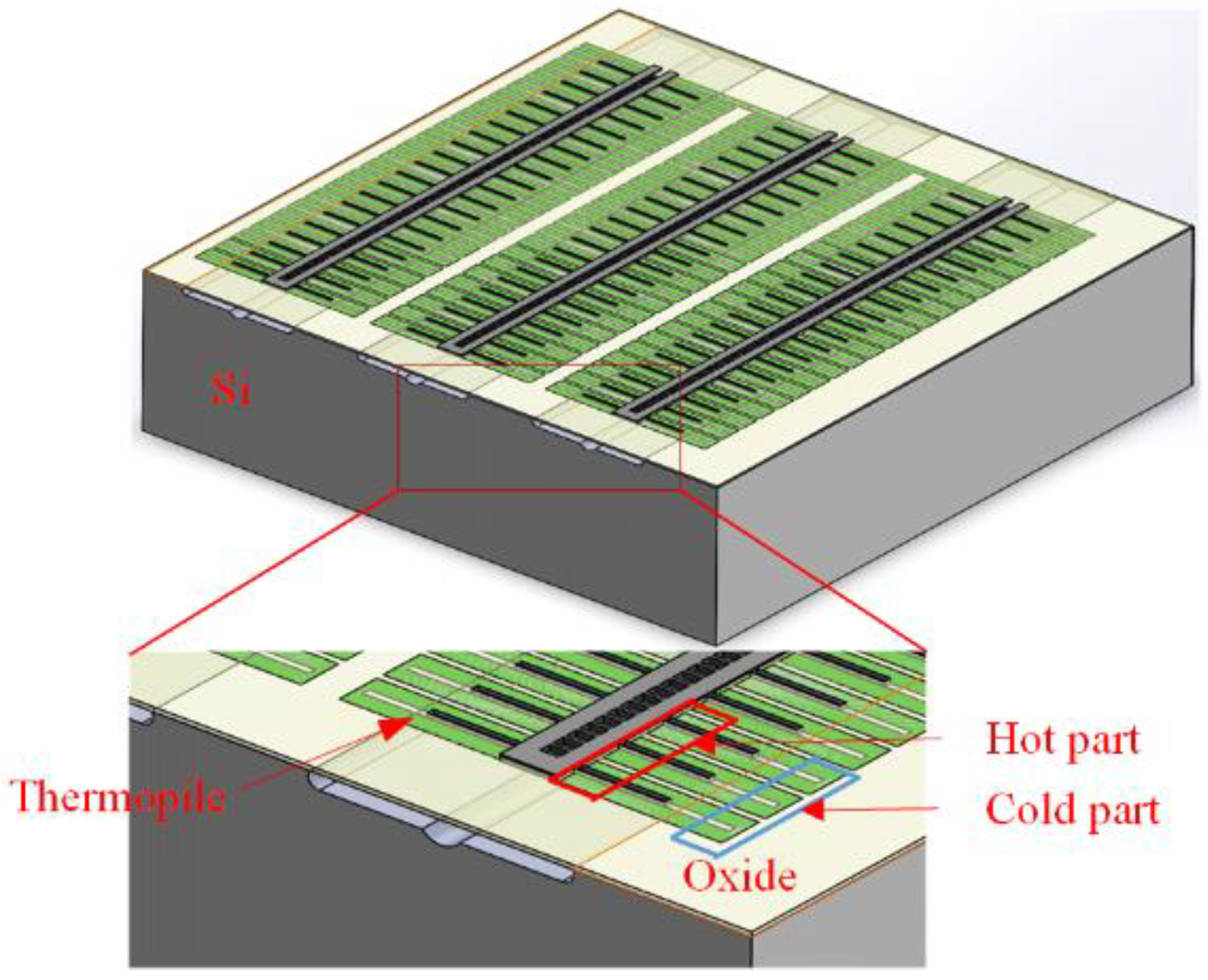
The TMG structure is illustrated in Figure 1. The microgenerator is constructed by thermopiles, thermometers, and CNCs film. There are 129 thermopiles in series. Each thermopile includes n-type and p-type polysilicon.
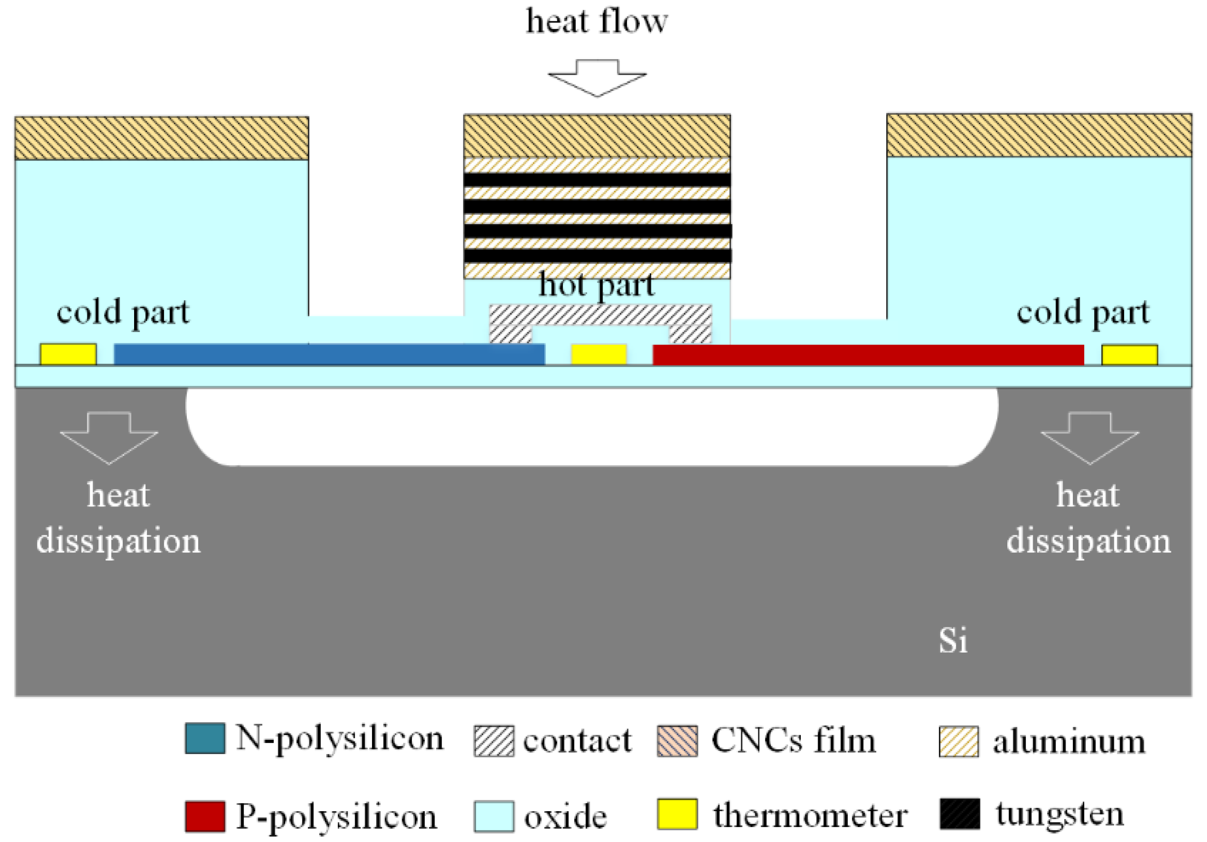
Figure 2 illustrates the schematic thermoelectric microgenerator cross-sectional structure. P-type and n-type polysilicon junctions in thermopiles are designed as hot and cold parts. According to the Seebeck effect [22], the greater the temperature difference of HP and CP in thermopiles is, the more increased the output voltage of the TMG becomes. To enhance the temperature difference of HP and CP, the hot part is designed as a suspension structure to isolate heat dissipation. A stacked metal layer with tungsten and aluminum, which covers the top of the hot part, increases heat conducting to the hot part because metal has a higher thermal conductivity than silicon oxide. The cold part anchors on the silicon substrate to increase heat dissipation, and a low thermal conductivity silicon oxide layer covers the cold part to reduce heat absorption. The CNCs layer is deposited on the surface of the microgenerator, and the layer is used to enhance heat absorption of the microgenerator. The thermometers are arranged at HP and CP in thermopiles, and they are employed to detect the temperature at HP and CP. The microgenerator area is 1.28 × 1.2 mm2. The length, thickness, and width of each thermopile are 180 μm, 0.2 μm, and 20 μm, respectively.
The operation mechanism of the TMG is demonstrated in Figure 2. Heat radiates to the CNCs film and is absorbed by the film. The heat absorbed by CNCs has two conducting ways. One conducts to the hot part through the metal layer, and the other conducts to the cold part through the thick silicon oxide layer. The thermal conductivity of metal is better than that of silicon oxide, so the metal layer is good for heat conducting to the hot part. The hot part that is part of the suspension structure can keep heat well. The heat at the cold part is dissipated through the silicon substrate. Thereby, the temperature at the hot part is higher than the temperature at the cold part, resulting in a temperature difference between HP and CP. The output voltage of the TMG is given by [23],
where n is the thermopile number, αn represents the n-type polysilicon Seebeck coefficients, αp represents the p-type polysilicon Seebeck coefficients, Th is the HP temperature, and Tc is the CP temperature. Th − Tc represents TD between HP and CP. αn − αp is the Seebeck coefficient difference of n-type and p-type polysilicon. The higher the thermopile number and TD between the HP and CP are, the more increased the microgenerator OV becomes. In this evaluation, there are 129 thermopiles and αn − αp is 8.14 μV/K. The values are substituted into Equation (1), and we obtain the microgenerator OV. Figure 3 shows the evaluated OV of the microgenerator. The results show that the microgenerator OV is 3.1 mV at TD 3 K.
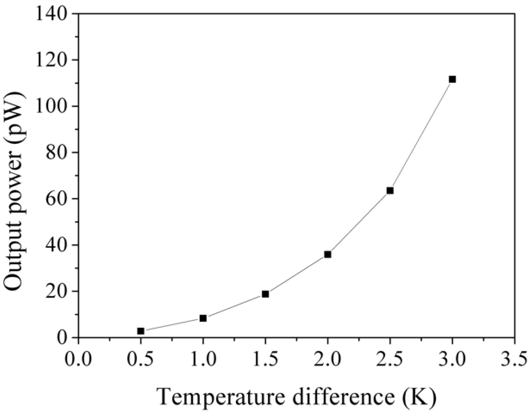
The output power of the TMG is given by [24],
where Rg is the microgenerator internal resistance. The output power is inversely proportional to microgenerator internal resistance and is related to the square of its output voltage. As the microgenerator internal resistance reduces, the microgenerator OP enhances. The internal resistance of the TMG is given by [25],
where ρp represents the p-type polysilicon resistivity of the thermocouple, Lp is the p-type polysilicon length of the thermocouple, tp is the p-type polysilicon thickness of the thermocouple, Wp is the p-type polysilicon width, ρn is the n-type polysilicon resistivity of the thermocouple, Ln is the n-type polysilicon length of the thermocouple, tn is the n-type polysilicon thickness of the thermocouple, and Wn is the n-type polysilicon width. The microgenerator internal resistance is proportional to thermopile length and resistivity, and it is inversely proportional to thermopile width and thickness. In this microgenerator, the number of the thermopiles is 129, Lp = 180 μm, Ln = 180 μm, Wp = 20 μm, Wn = 20 μm, tp = 0.2 μm, and tn = 0.2 μm. The values are substituted into Equation (3), and we can see that the internal resistance of the microgenerator is 21.8 kΩ. According to Equation (2), the microgenerator OP is obtained using the values in Figure 3 and Rg = 21.8 kΩ. Figure 4 demonstrates the evaluated output power of the microgenerator. The evaluated results reveal that the microgenerator OP is 111 pW at TD 3 K.
The thermometer is a resistive type. The material of the thermometer is polysilicon. Length and width of thermometer are 2925 μm and 0.3 μm, respectively. Sheet resistance of polysilicon for the thermometer is 8.3 Ω/sq. The initial resistance of the thermometer at room temperature is given by [26],
where Rs denotes the thermometer sheet resistance, L is the thermometer length, and W is the thermometer width. The values Rs = 8.3 Ω/sq, L = 2925 μm, and W = 0.3 μm are substituted into Equation (4), and we compute that the initial resistance of the thermometer at room temperature is 80.9 kΩ. The resistance of the thermometer with respect to temperature is given by [26],
where R0 is the thermometer initial resistance, αT is the temperature coefficient of the resistor for the thermometer, T is the temperature, and T0 is the initial temperature. The temperature coefficient of the resistor of the thermometer is 0.0015/°C. The value and R0 = 80.9 kΩ are substituted into Equation (5), and the resistance of the thermometer with respect to temperature can be yielded. Figure 5 reveals the resistance versus temperature in the thermometer.
3. Fabrication of Microgenerator
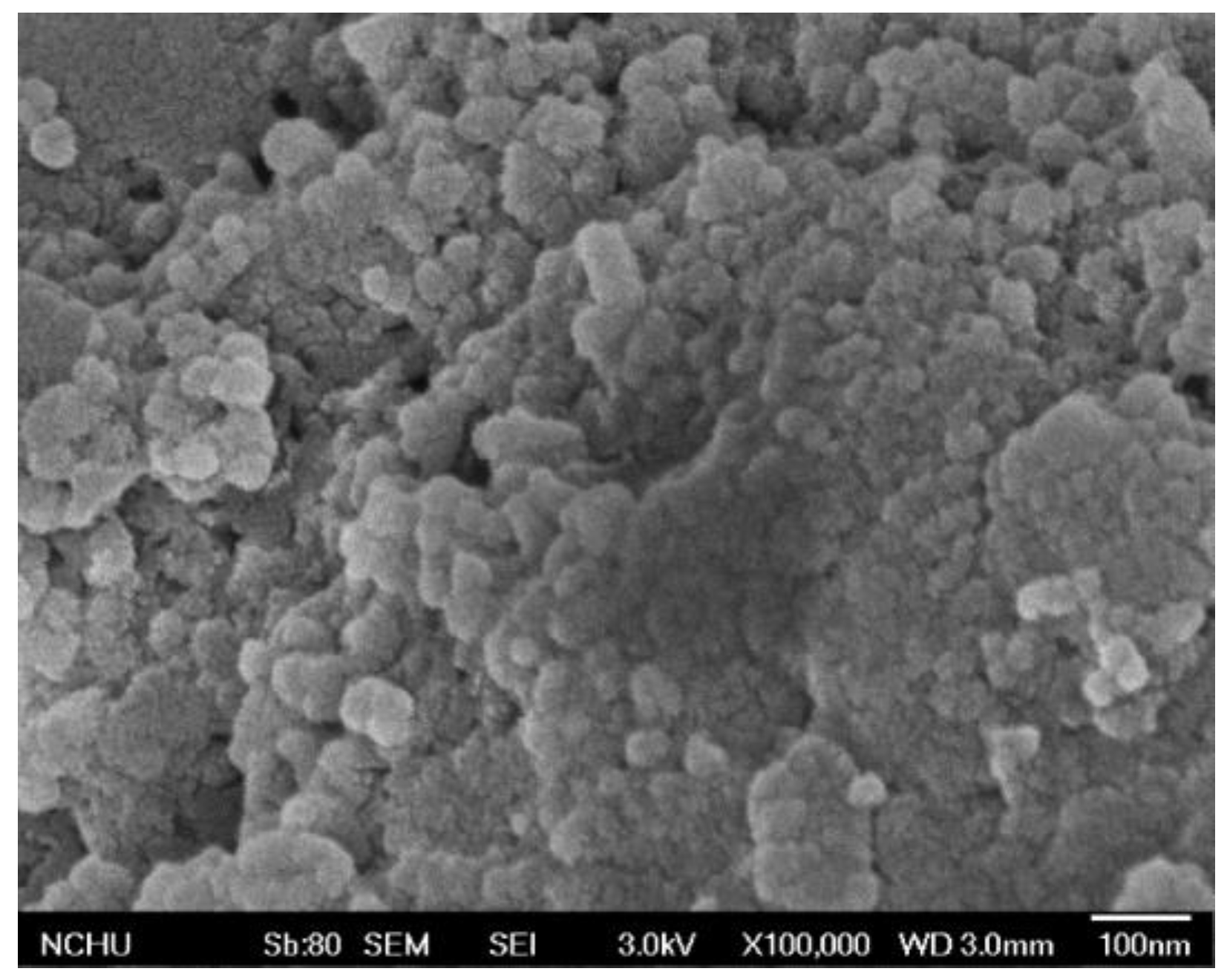
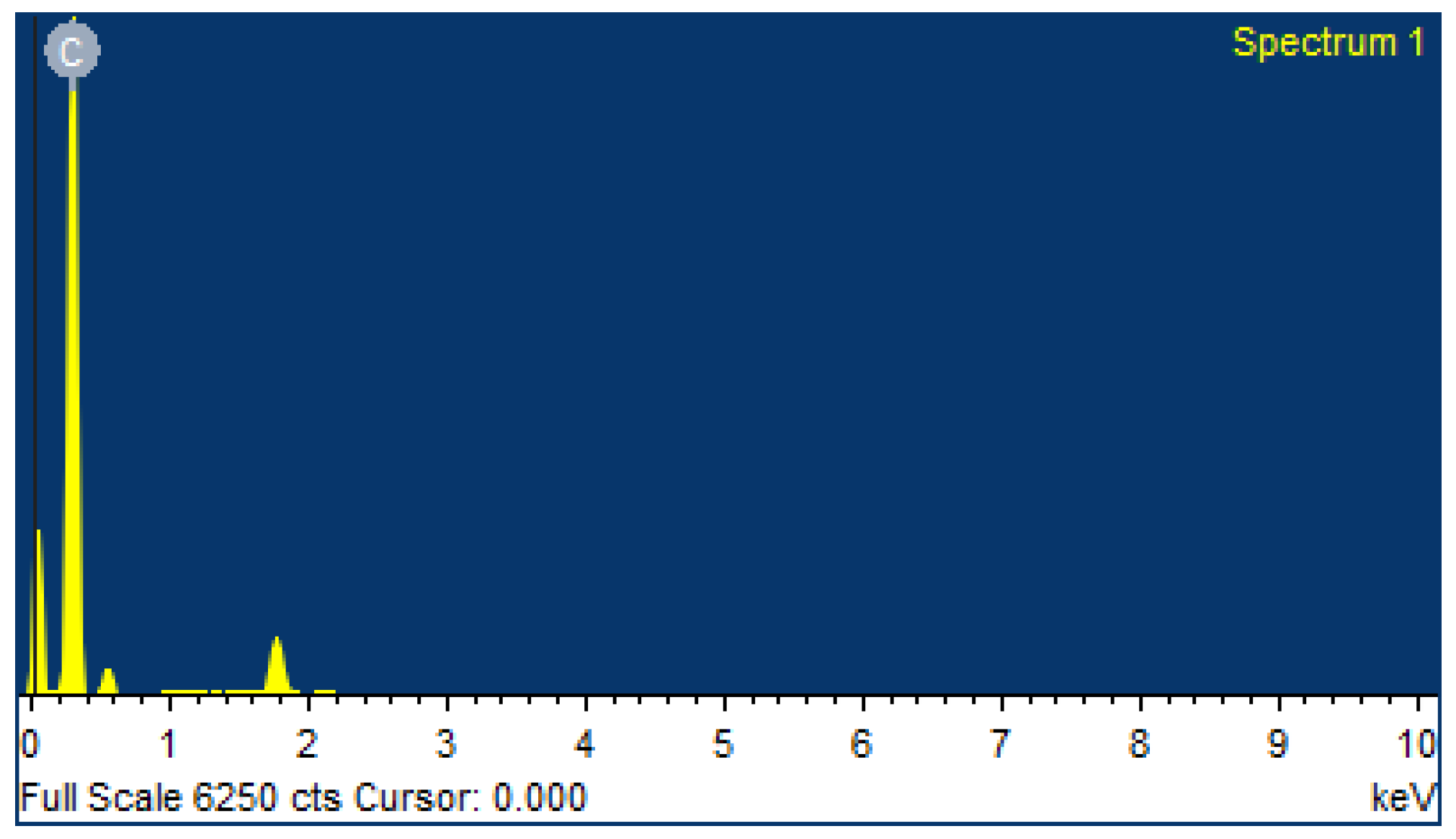
To increase the heat absorption of the thermoelectric microgenerator, a CNCs film which was a heating absorbing material was coated on the surface of the microgenerator. The preparation of the CNCs film was completed as follows. Carbon nanocapsules powder of 3 g was dissolved in ethanol with stirring, followed by mixing the solution uniformly. The slurry of CNCs was filtered, and it was deposited on the TMG surface, followed by baking at 120 °C for 1 h. Figure 6 demonstrates a scanning electron microscope (SEM) picture of the CNCs. Figure 7 depicts an energy dispersive spectrometer (EDS) image of the CNCs film, where the main elements are carbon.
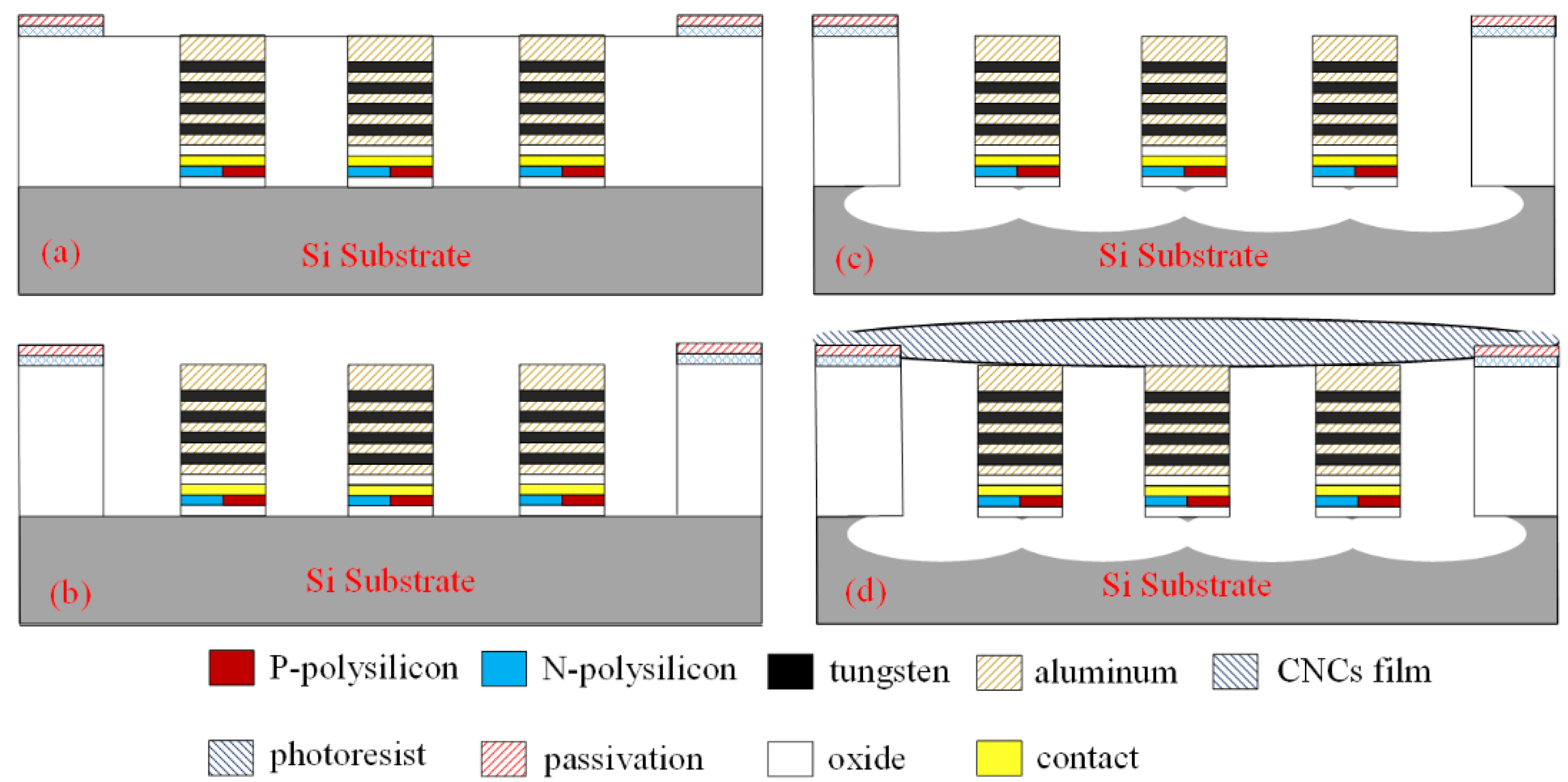
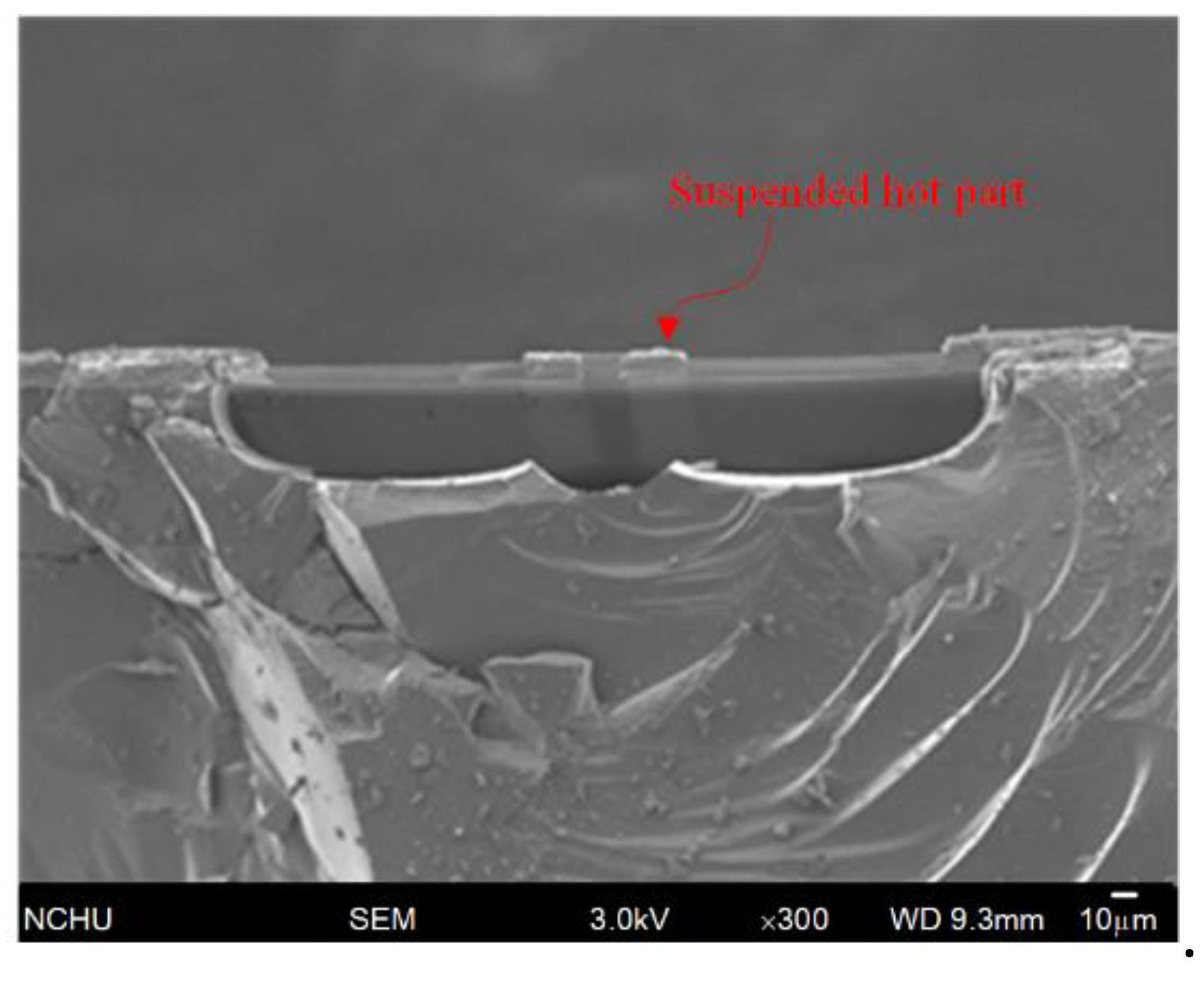
Figure 8 presents the thermoelectric microgenerator manufacturing flow. Taiwan Semiconductor Manufacturing Company (TSMC) employed a CMOS process to make the microgenerator [27]. Figure 8a illustrates the TMG cross-sectional view after completion of the CMOS process. The microgenerator required post-CMOS processing to form the HP suspension structure in thermopiles. The post-CMOS processing [28,29] was used to etch sacrificial layers of the microgenerator. The sacrifice layers are silicon oxide and silicon substrate. The post-process included removing silicon oxide and silicon substrate. As shown in Figure 8b, a photoresist was patterned by the photolithography process. Then, anisotropic dry etching with reactive ion etching (RIE) CHF3/O2 was adopted, thus removing silicon oxide and exposing silicon substrate. As presented in Figure 8c, RIE XeF2/O2 isotropic etching was utilized to remove the substrate. The HP suspension structure in thermopiles was obtained. A stacked metal layer with aluminum and tungsten had a higher thermal conductivity than silicon oxide, and it was good for heat conducting to the hot part in the thermopiles. Figure 9 demonstrates an SEM picture of the microgenerator post-CMOS process. Figure 10 demonstrates an SEM picture of the cross-sectional view of the microgenerator. As illustrated in Figure 10, the hot part of the microgenerator is suspended.
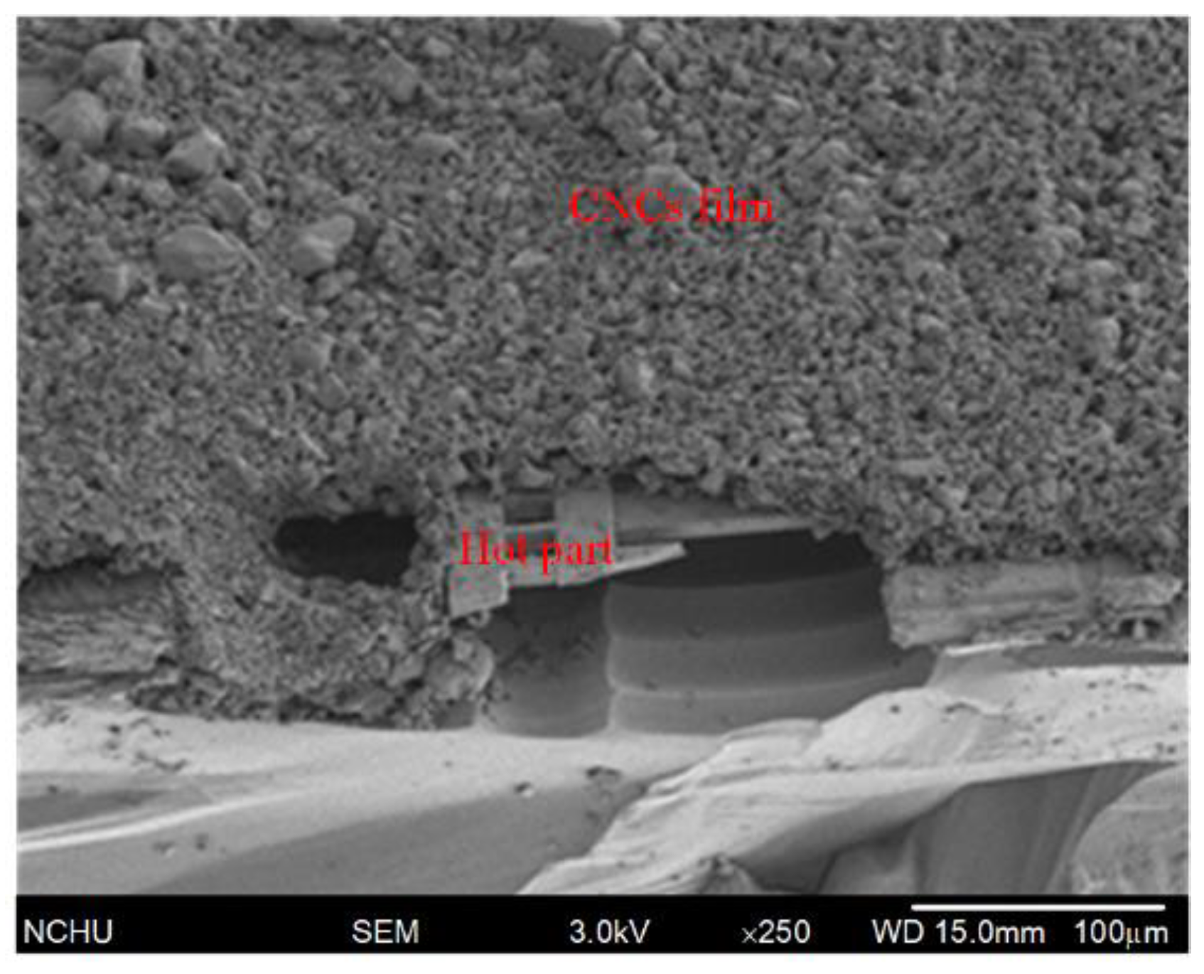
Finally, the CNCs heat absorption film was deposited on the microgenerator. As demonstrated in Figure 8d, CNCs were deposited on the surface of the microgenerator utilizing a precision-control dropper system, followed by baking at 120 °C for 1 h. Figure 11 demonstrates an SEM picture of the microgenerator with the CNCs film.
4. Results
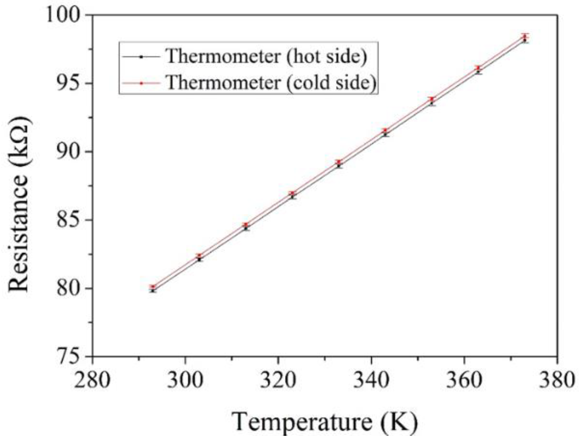
The thermoelectric microgenerator contained two thermometers, where one was located at the hot part of the thermopiles and the other was located at the cold part of the thermopiles. The thermometer was employed to detect the temperature of HP and CP in the thermopiles. A heat chamber, a temperature detector, and a digital multimeter were used to measure the performance of the thermometers. The thermometers were set in a heat chamber. The heat chamber gave a heat source to the thermometers. The temperature detector calibrated the temperature in the heat chamber. The digital multimeter recorded the resistance change of the thermometers. Figure 12 shows resistance versus temperature in the thermometer. The results showed that the ratio of resistance and temperature at the cold part thermometer was the same as that at the hot part thermometer.
The TMG performance was tested utilizing a heater, a cooler, a PID (proportional integral derivative) controller, and digital multimeters. The heater supplied heat to the microgenerator. The cooler provided cooling to the microgenerator. The PID controller was utilized to control the heat source of the heater and to control the function of the cooler. The digital multimeters measured the microgenerator OV and thermometers resistance. The thermometers in the microgenerator directly measured the TD of the cold and hot parts in the microgenerator.
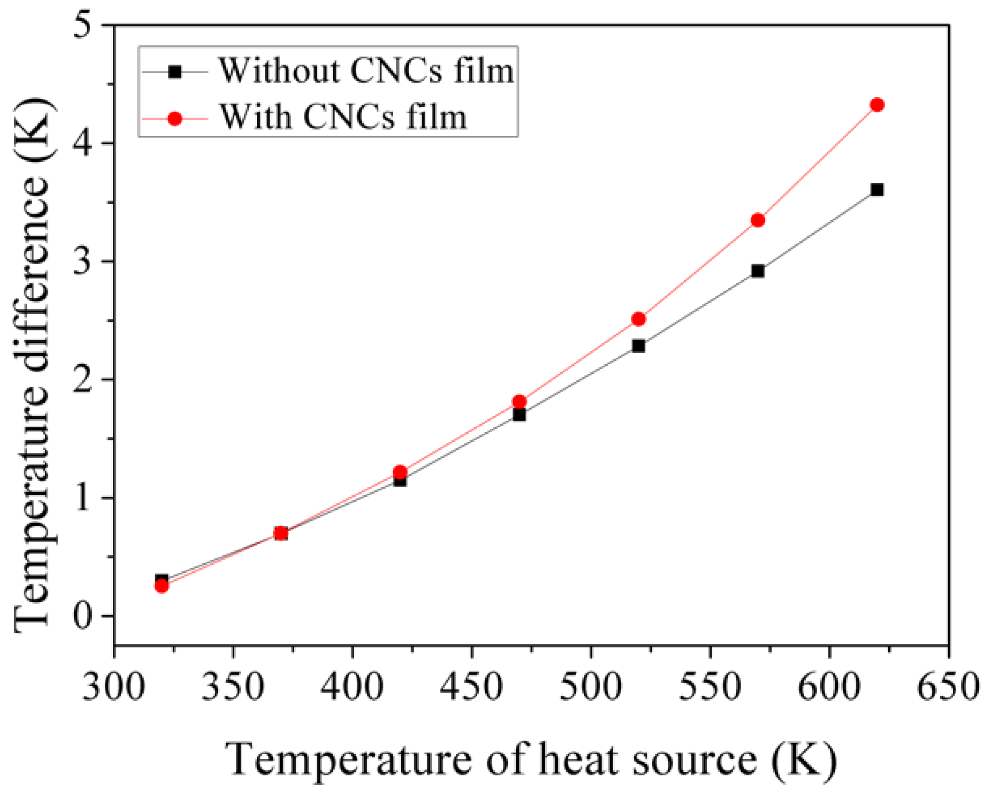
To characterize the heat absorption effect of the CNCs film, the microgenerator with the CNCs film and one without the CNCs film were tested, respectively. The microgenerator without the CNCs film was set on the testing system. The heat was given by heater, and cooling was supplied by the cooler. The thermometers measured the temperature difference of HP and CP in the microgenerator. Figure 13 reveals the measurement results of the microgenerator without the CNCs film. Then, the microgenerator with the CNCs film was tested. Figure 13 presents the measurement results of the microgenerator with the CNCs film. The results depicted that the temperature difference of the microgenerator with CNCs exceeded that without CNCs at the same heat source. The CNCs film had a heat absorption effect.
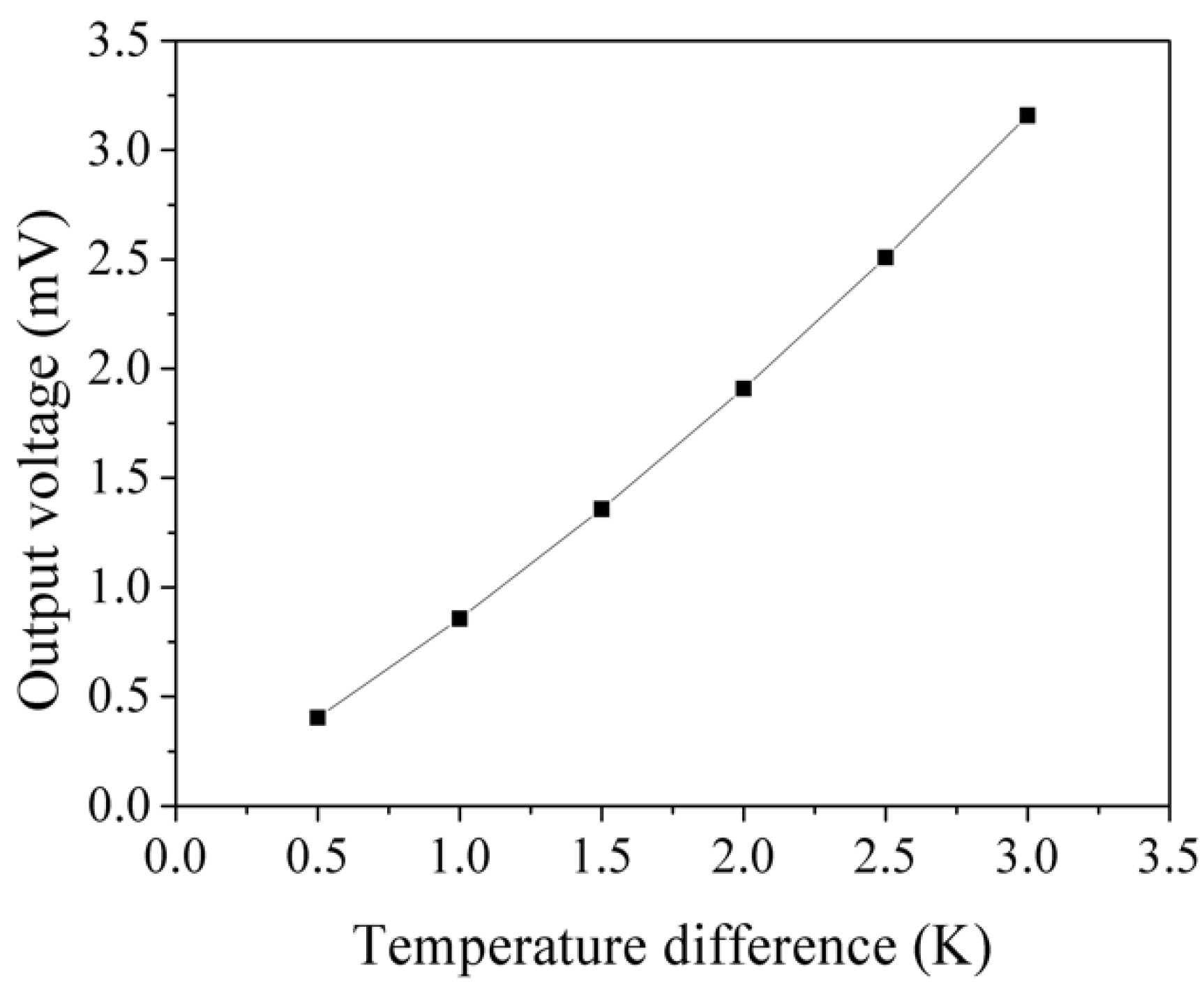
The OV of the thermoelectric microgenerator with the CNCs film was tested. Figure 14 shows the measured OV of the microgenerator with the CNCs film. The measured results showed that the microgenerator OV was 3.3 mV at TD of 3 K. When comparing the experiment and simulation results, the error percentage of the microgenerator OV was 6%.
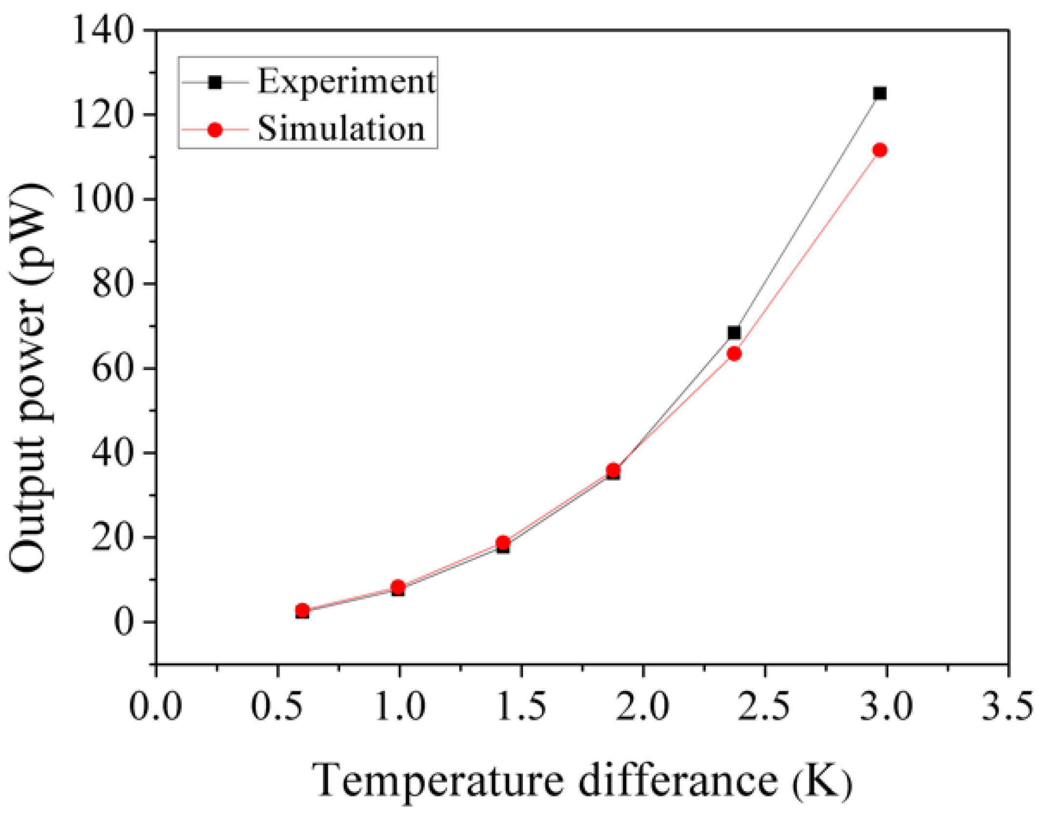
The OP of the thermoelectric microgenerator with the CNCs film can be obtained in accordance with Equation (2). The initial resistance of the microgenerator was 21.8 kΩ. The measured OV as shown in Figure 14 and the initial resistance value were substituted into Equation (2), and the OP of the microgenerator with the CNCs film was obtained. Figure 15 depicts the measured OP of the microgenerator. The results showed that the microgenerator OP was 125 pW at TD 3 K. Area of the microgenerator was 1.28 × 1.2 μm2. According to the measured OV and OP of the microgenerator with the CNCs film, we evaluated the voltage factor and power factor of the microgenerator. The voltage factor of the microgenerator was 0.71 mV/K/mm2, and its power factor was 9.04 pW/K2/mm2. Table 1 shows a list of voltage and power factors for various thermoelectric microgenerators. As depicted in Table 1, the voltage factor and power factor of the microgenerator in this work exceed that of Kao [27], Jo [30], Siddique [31], Peng [32], and Yeh [33].
5. Conclusions
The manufacture of a microgenerator with a CNCs film was carried out employing a CMOS-MEMS technology. Experiments showed that the TD of thermopiles in the microgenerator with CNCs exceeded that without a CNCs film. The CNCs film had a heat absorption effect, which enhanced the thermopile temperature difference, so that the microgenerator output power increased. To enhance the temperature difference of the thermopiles in the microgenerator, the hot part in the microgenerator was etched as suspension structures. The cold part in the microgenerator was anchored on silicon substrate and covered with a low thermal conductivity silicon dioxide layer. The post-process employed RIE etching to form hot part suspension structures in the microgenerator and coated the CNCs film on the microgenerator surface. The tested results depicted that the microgenerator output voltage was 3.3 mV and its output power was 125 pW at TD 3 K. Voltage factor of the microgenerator was 0.71 mV/K/mm2 and its power factor was 9.04 pW/K2/mm2. The CNCs film enhanced heat absorption of the hot part in the microgenerator and increased the temperature difference of the microgenerator. Comparing to the microgenerators [27,30,31,32,33] shown in Table 1, the voltage and power factors of the microgenerator in this work exhibited a little enhancement.
Author Contributions
Y.-W.C. carried out the fabrication and measurement of the thermoelectric microgenerator. C.-C.W. and C.-C.H. analyzed the performance of the thermoelectric microgenerator. C.-L.D. supervised the work of Y.-W.C. and wrote the paper. All authors read and approved the final manuscript.
Funding
This research was funded by the Ministry of Science and Technology (MOST) of the Republic of China grant number MOST 105-2221-E-005-037-MY3 and MOST 106-2221-E-005-050-MY2.
Acknowledgments
The authors would like to thank the National Center for High-performance Computing (NCHC) for chip simulation, National Chip Implementation Center (CIC) for chip fabrication and the MOST of the Republic of China for financially supporting.
Conflicts of Interest
The authors declare no conflict of interest.
References
- Tian, W.; Ling, Z.; Yu, W.; Shi, J. A review of MEMS scale piezoelectric energy harvester. Appl. Sci. 2018, 8, 645. [Google Scholar] [CrossRef]
- Lin, C.Y.; Hsu, C.C.; Dai, C.L. Fabrication of a micromachined capacitive switch using the CMOS-MEMS technology. Micromachines 2015, 6, 1645–1654. [Google Scholar] [CrossRef]
- Blanche, P.A.; LaComb, L.; Wang, Y.; Wu, M.C. Diffraction-based optical switching with MEMS. Appl. Sci. 2017, 7, 411. [Google Scholar] [CrossRef]
- Huang, C.Y.; Chen, J.H. Development of dual-axis MEMS accelerometers for machine tools vibration monitoring. Appl. Sci. 2016, 6, 201. [Google Scholar] [CrossRef]
- Fong, C.F.; Dai, C.L.; Wu, C.C. Fabrication and characterization of a micro methanol sensor using the CMOS-MEMS technique. Sensors 2015, 15, 27047–27059. [Google Scholar] [CrossRef] [PubMed]
- Zhang, W.; Yang, J.; Xu, D. A high power density micro-thermoelectric generator fabricated by an integrated bottom-up approach. J. Microelectromech. Syst. 2016, 25, 744–749. [Google Scholar] [CrossRef]
- Yuan, Z.; Ziouche, K.; Bougrioua, Z.; Lejeune, P.; Lasri, T.; Leclercq, D. A planar micro thermoelectric generator with high thermal resistance. Sens. Actuators A Phys. 2015, 221, 67–76. [Google Scholar] [CrossRef]
- Perez-Marin, A.P.; Lopeandia, A.F.; Abad, L.; Ferrando-Villaba, P.; Garcia, G.; Lopez, A.M.; Munoz-Pascual, F.X.; Rodriguez-Viejo, J. Micropower thermoelectric generator from thin Si membranes. Nano Energy 2014, 4, 73–80. [Google Scholar] [CrossRef] [Green Version]
- Kouma, N.; Nishino, T.; Tsuboi, O. A high-output-voltage micro-thermoelectric generator having high-aspect-ratio structure. J. Micromech. Microeng. 2013, 23, 114005. [Google Scholar] [CrossRef]
- Feng, Q.; Shi, X.; Xing, Y.; Li, T.; Li, F.; Pan, D.; Liang, H. Thermoelectric microgenerators using a single large-scale Sb doped ZnO microwires. J. Alloys Compd. 2018, 739, 298–304. [Google Scholar] [CrossRef]
- Yamamuro, H.; Hatsuta, N.; Wachi, M.; Takei, Y.; Takashiri, M. Combination of Electrodeposition and Transfer Processes for Flexible Thin-Film Thermoelectric Generators. Coatings 2018, 8, 22. [Google Scholar] [CrossRef]
- Hashimoto, S.; Asada, S.; Xu, T.; Oba, S.; Himeda, Y.; Yamato, R.; Matsukawa, T.; Matsuki, T.; Watanabe, T. Anomalous Seebeck coefficient observed in silicon nanowire micro thermoelectric generator. Appl. Phys. Lett. 2017, 111, 023105. [Google Scholar] [CrossRef]
- Maruyama, S.; Hizawa, T.; Takahashi, K.; Sawada, K. Optical-interferometry-based CMOS-MEMS sensor transduced by stress-induced nanomechanical deflection. Sensors 2018, 18, 138. [Google Scholar] [CrossRef] [PubMed]
- Liao, W.Z.; Dai, C.L.; Yang, M.Z. Micro ethanol sensors with a heater fabricated using the commercial 0.18 μm CMOS process. Sensors 2013, 13, 12760–12770. [Google Scholar] [CrossRef] [PubMed]
- Mansoor, M.; Haneef, I.; Akhtar, S.; Rafiq, M.A.; De Luca, A.; Ali, S.Z.; Udrea, F. An SOI CMOS-based multi-sensor MEMS chip for fluidic applications. Sensors 2016, 16, 1608. [Google Scholar] [CrossRef] [PubMed]
- Yang, M.Z.; Dai, C.L.; Lin, W.Y. Fabrication and characterization of polyaniline/PVA humidity microsensors. Sensors 2011, 11, 8143–8151. [Google Scholar] [CrossRef] [PubMed]
- Hu, Y.C.; Dai, C.L.; Hsu, C.C. Titanium dioxide nanoparticle humidity microsensors integrated with circuitry on-a-chip. Sensors 2014, 14, 4177–4188. [Google Scholar] [CrossRef] [PubMed] [Green Version]
- Wang, Y.; Chodavarapu, V.P. Differential wide temperature range CMOS interface circuit for capacitive MEMS pressure sensors. Sensors 2015, 15, 4253–4263. [Google Scholar] [CrossRef] [PubMed]
- Yang, M.Z.; Dai, C.L. Ethanol microsensors with a readout circuit manufactured using the CMOS-MEMS technique. Sensors 2015, 15, 1623–1634. [Google Scholar] [CrossRef] [PubMed]
- Dai, C.L.; Peng, H.J.; Liu, M.C.; Wu, C.C.; Hsu, H.M.; Yang, L.J. A micromachined microwave switch fabricated by the complementary metal-oxide semiconductor post-process of etching silicon dioxide. Jpn. J. Appl. Phys. 2005, 44, 6804–6809. [Google Scholar] [CrossRef]
- Székely, V. New type of thermal-function IC: 4-quadrant multiplier. Electron. Lett. 1976, 12, 372–373. [Google Scholar] [CrossRef]
- Ankireddy, K.; Menon, A.K.; Iezzi, B.; Yee, S.K.; Losego, M.D.; Jur, J.S. Electrical conductivity, thermal behavior, and Seebeck coefficient of conductive films for printed thermoelectric energy harvesting systems. J. Electron. Mater. 2016, 45, 5561–5569. [Google Scholar] [CrossRef]
- Strasser, M.; Aigner, R.; Lauterbach, C.; Sturm, T.F.; Franosch, M.; Wachutka, G. Micro machined CMOS TEG as on-chip power supply. Sens. Actuators A 2004, 144, 362–370. [Google Scholar] [CrossRef]
- Toriyama, T.; Yajima, M.; Sugiyama, S. Thermoelectric micro power generator utilizing self-standing polysilicon-metal thermopile. In Proceedings of the IEEE Micro Electro Mechanical Systems, Interlaken, Switzerland, 25 January 2001; pp. 562–565. [Google Scholar]
- Glatz, W.; Muntwyler, S.; Hierold, C. Optimization and fabrication of thick flexible polymer based micro thermoelectric generator. Sens. Actuators A Phys. 2006, 132, 337–345. [Google Scholar] [CrossRef]
- Gardner, J.W.; Varadan, V.K.; Awadelkarim, O.O. Microsensors MEMS and Smart Devices; John Wiley & Sons Ltd.: Chichester, UK, 2001. [Google Scholar]
- Kao, P.H.; Shih, P.J.; Dai, C.L.; Kiu, M.C. Fabrication and Characterization of CMOS-MEMS Thermoelectric Micro Generator. Sensors 2010, 10, 1315–1325. [Google Scholar] [CrossRef] [PubMed] [Green Version]
- Dai, C.L.; Chiou, J.H.; Lu, M.S.C. A maskless post-CMOS bulk micromachining process and its application. J. Micromech. Microeng. 2005, 15, 2366–2371. [Google Scholar] [CrossRef]
- Dai, C.L.; Chen, H.L.; Chang, P.Z. Fabrication of a micromachined optical modulator using the CMOS process. J. Micromech. Microeng. 2001, 11, 612–615. [Google Scholar] [CrossRef]
- Jo, S.E.; Kim, M.K.; Kim, M.S.; Kim, Y.J. Flexible thermoelectric generator for human body heat energy harvesting. Electron. Lett. 2012, 48, 1015–1017. [Google Scholar] [CrossRef]
- Siddique, A.R.M.; Rabari, R.; Mahmud, S.; Heyst, B.V. Thermal energy harvesting from the human body using flexible thermoelectric generator (FTEG) fabricated by a dispenser printing technique. Energy 2016, 115, 1081–1091. [Google Scholar] [CrossRef]
- Peng, S.W.; Shih, P.J.; Dai, C.L. Manufacturing and characterization of a thermoelectric energy harvester using the CMOS-MEMS technology. Micromachines 2015, 6, 1560–1568. [Google Scholar] [CrossRef]
- Yeh, C.C.; Dai, C.L.; Shih, H.F. Fabrication and characterization of thermoelectric microgenerators with carbon nanotube. Sens. Mater. 2014, 26, 75–83. [Google Scholar]
Figure 1.
Thermoelectric microgenerator structure.

Figure 2.
Schematic thermoelectric microgenerator cross-sectional structure.

Figure 3.
Evaluated output voltage of the microgenerator.

Figure 4.
Evaluated output power of the microgenerator.

Figure 5.
Evaluated resistance of the thermometer.
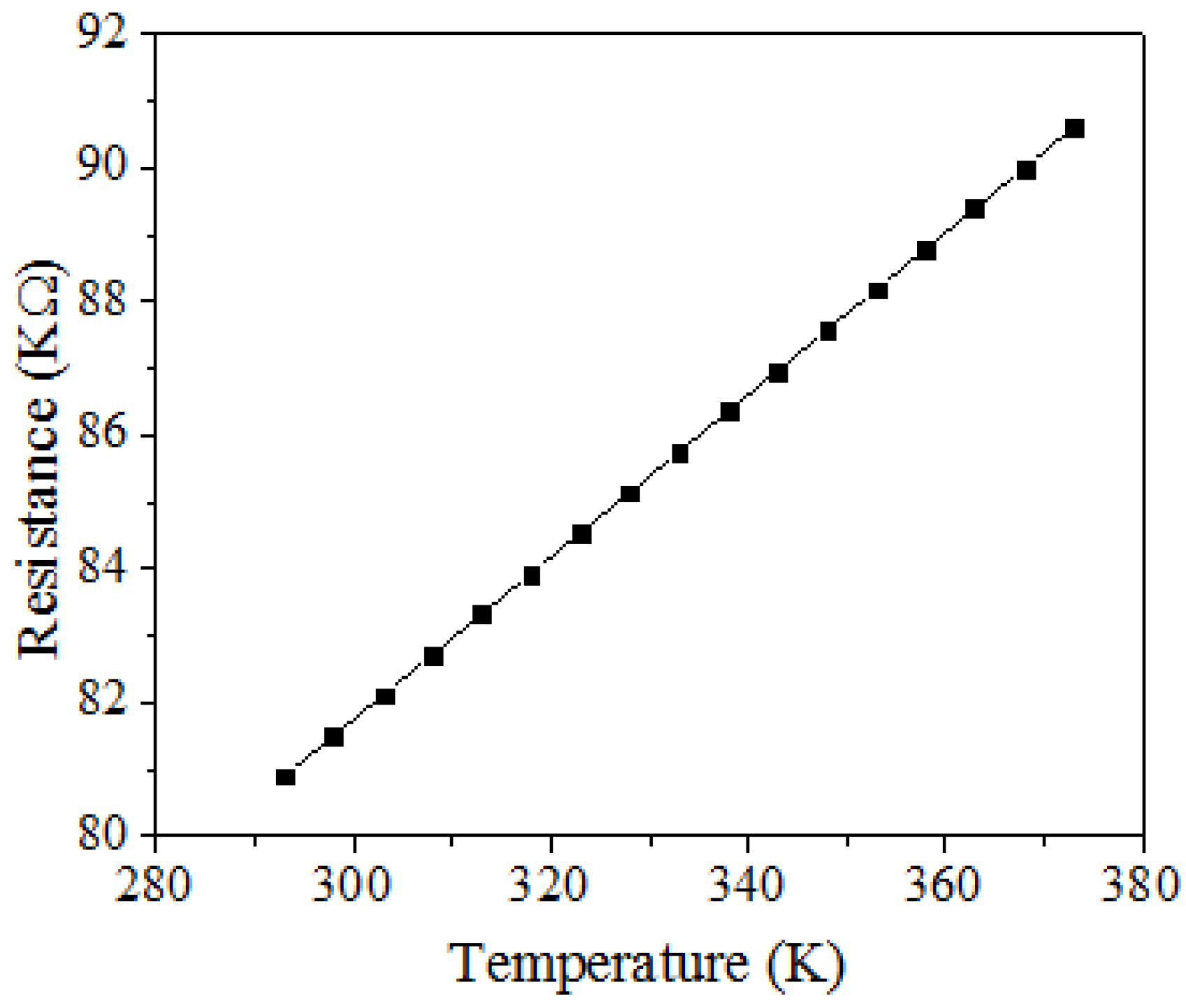
Figure 6.
CNCs (carbon nanocapsules) picture measured by SEM.

Figure 7.
CNCs components measured by energy dispersive spectrometer.

Figure 8.
Fabrication of the microgenerator, (a) completion of CMOS process; (b) etching silicon oxide; (c) removing substrate; (d) coating CNCs film.
Figure 8.
Fabrication of the microgenerator, (a) completion of CMOS process; (b) etching silicon oxide; (c) removing substrate; (d) coating CNCs film.

Figure 9.
SEM picture of the microgenerator post-CMOS processing.
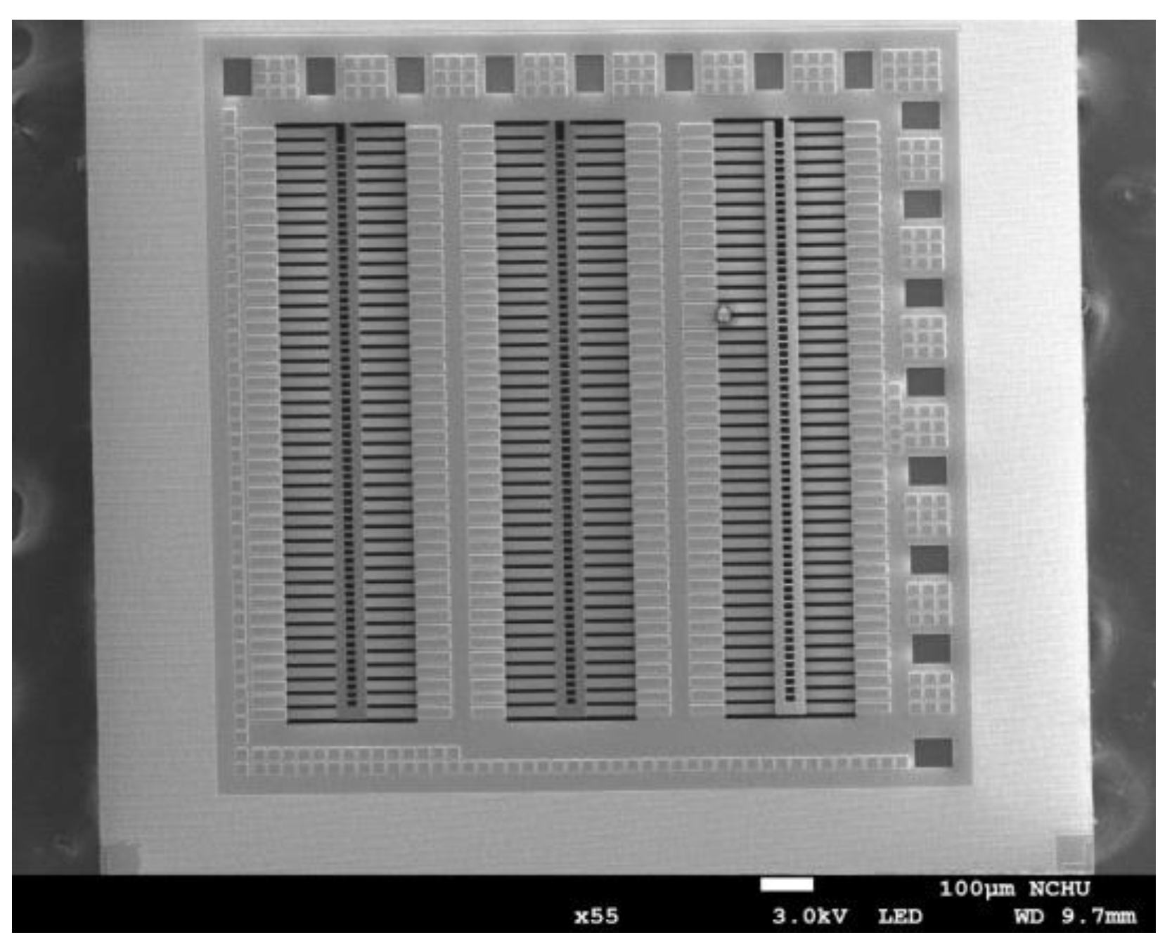
Figure 10.
Cross-sectional view of the microgenerator.

Figure 11.
SEM picture of the microgenerator with CNCs film.

Figure 12.
Measured resistance of the thermometers.

Figure 13.
Temperature difference of the microgenerator.

Figure 14.
Measured OV of the microgenerator.
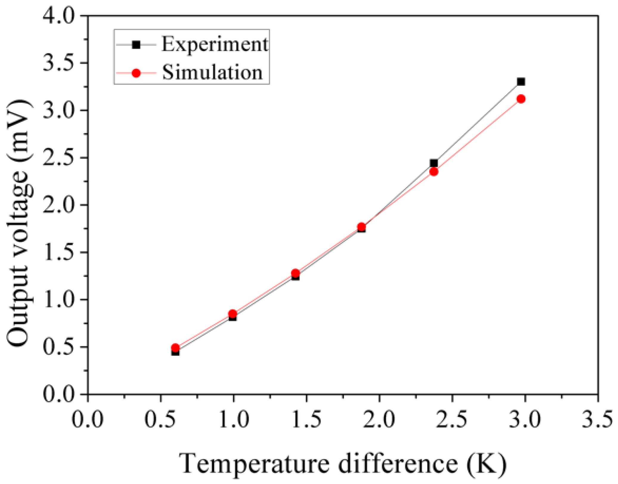
Figure 15.
Measured OP of the microgenerator.


© 2018 by the authors. Licensee MDPI, Basel, Switzerland. This article is an open access article distributed under the terms and conditions of the Creative Commons Attribution (CC BY) license (http://creativecommons.org/licenses/by/4.0/).
Share and Cite
MDPI and ACS Style
Chen, Y.-W.; Wu, C.-C.; Hsu, C.-C.; Dai, C.-L. Fabrication and Testing of Thermoelectric CMOS-MEMS Microgenerators with CNCs Film. Appl. Sci. 2018, 8, 1047. https://doi.org/10.3390/app8071047
AMA Style
Chen Y-W, Wu C-C, Hsu C-C, Dai C-L. Fabrication and Testing of Thermoelectric CMOS-MEMS Microgenerators with CNCs Film. Applied Sciences. 2018; 8(7):1047. https://doi.org/10.3390/app8071047
Chicago/Turabian StyleChen, Yu-Wei, Chyan-Chyi Wu, Cheng-Chih Hsu, and Ching-Liang Dai. 2018. "Fabrication and Testing of Thermoelectric CMOS-MEMS Microgenerators with CNCs Film" Applied Sciences 8, no. 7: 1047. https://doi.org/10.3390/app8071047
Note that from the first issue of 2016, this journal uses article numbers instead of page numbers. See further details here.