Modeling and Solving Method for Supporting ‘Vehicle-to-Anything’ EV Charging Mode


1
State Key Laboratory of HVDC, Electric Power Research Institute, China Southern Power Grid, Guangzhou 510663, China
2
School of Electrical and Electronic Engineering, Nanyang Technological University, 50 Nanyang Avenue, Singapore 639798, Singapore
*
Author to whom correspondence should be addressed.
Appl. Sci. 2018, 8(7), 1048; https://doi.org/10.3390/app8071048
Submission received: 29 May 2018
/
Revised: 13 June 2018
/
Accepted: 13 June 2018
/
Published: 27 June 2018
(This article belongs to the Special Issue Electric Vehicle Charging)
Abstract
:Electric vehicles (EVs) are an attractive solution to make traditional transportation energy-efficient and environmentally friendly. EVs are also considered an important element to bring new opportunities for power grids. In addition to the role of a pure load, along with the development of discharging technology for batteries, EVs can deliver energy back to power grids or another power consumption entity or community, performing various discharging activities such as vehicle-to-home (V2H), vehicle-to-building (V2B), vehicle-to-vehicle (V2V), vehicle-to-grid (V2G), etc. These charging scenarios can be uniformly named the ‘Vehicle-to-anything’ (V2A) charging mode. The paradigm of this charging mode has already been given; however, the modeling and solving approaches are still insufficient. Therefore, the analysis and modeling of V2A are investigated herein. The aim is to propose a generic model suitable for different applications of V2A in different places. The characteristics of the V2A charging mode are given and analyzed first. Then a model that can adapt to the V2A scenario is illustrated. The optimization problem is transformed and solved as an INLP (integer nonlinear programming) problem. The effectiveness of the approach is verified with simulation results. The outcome also indicates that V2A applications have great potential for lowering power consumption costs; for instance, a reduction of 4.37% in energy expense can be achieved in a case study with EV discharging enabled for a household.
1. Introduction
Electric vehicles (EVs) are an attractive transportation option that provides appealing benefits by reducing the use of fossil fuels with high energy efficiency and combatting CO2 emissions. As an alternative to traditional petrol or diesel vehicles, EVs are now receiving unprecedented interest from numerous users, investors, and countries [1,2]. According to a recent report on the global electric car stock, worldwide sales of EVs have hit a new record with over 0.75 million in 2016 and the transition to electric road transport is likely to keep growing over the coming decades [3]. The fast development of EVs has also attracted researchers into power systems. EVs should rely on power grids in procuring energy for voyage support. To accommodate the charging of EVs, certain infrastructures such as charging stations, a communication link, and a control interface and system must be developed or implemented. The penetration of massive EVs will also challenge the operation of the power system, since the additional load of EV charging may potentially amplify the daily peak of power load curve and induce some adverse impacts including voltage drops, frequency oscillations, power congestion [4,5], etc.
Besides the load impact, it is also expected that an EV can direct energy back into the power grid by utilizing the discharging activity of the EV battery. This envisaged technology is well known as Vehicle-to-Grid (V2G) technology [6]. With V2G enabled, EVs can act as moving energy banks, capable of procuring energy from the power grid and also injecting energy back when necessary. Therefore, the power flow of V2G can be unidirectional (charging only) or bidirectional [7], and EV owners have the opportunity to earn extra profit through charging their cars at low-price time slots while selling energy back to power grid during periods with high power prices. The discharging ability also enables EVs to participate in other various charging/discharging activities such as home energy management (V2H, Vehicle-to-Home) [8], building energy management (V2B, Vehicle-to-Building) [9], and charging station energy management (V2V, Vehicle-to-Vehicle). In essence, these discharging behaviors are operated to compensate for the power demand from other loads, thus achieving the optimization of energy consumption and operational costs for certain power consumption entities or communities (home, building, charging station, residential area, and so on). The above EV discharging activities, including V2H, V2B, V2V, and V2G, can be uniformly named the ‘Vehicle-to-anything’ (V2A) charging mode [10].
In [10], a thorough discussion of V2A scenarios is given, including the challenges and opportunities involved in this technology. To support the various charging/discharging activities of V2A, communication infrastructures and technologies are needed for essential information exchange [11,12]. In addition, it is also advised to develop and apply the ‘Vehicle-to-anything’ app for EV energy management [13]. Previous studies gave some basic concepts/future expectations of V2A [10,11,12,13], or only focused on the partial application of this charging mode (V2H, V2G, or V2B) [8,9], while the modeling and supporting approach for a more comprehensive utilization of V2A technology is still insufficient.
In order to support the V2A scenarios, its charging activities are investigated. The aim herein is to develop a solving model that can adapt to V2A technology. The main contributions of this work lie in:
- (1)
- Based on basic findings of V2H, V2B, V2V, and V2G, all the applications of V2A are considered and a generic model that can adapt to V2A is proposed;
- (2)
- Besides the consideration of EV charging satisfaction for EV user, battery degradation that can affect EV charging/discharging behaviors is also considered in the model through the evaluation via battery charging/discharging cycles;
- (3)
- In the proposed model, each of the EV behaviors (including the status of charging, V2H, V2B, V2V, and V2G) is assigned a single Boolean vector and the created model is then transformed into an INLP (integer nonlinear programming) problem. An intelligent module with treatment for easing the calculated variables is also designed to guide the optimization for different applications of V2A.
The remaining paper is organized as follows: the paradigm of V2A charging mode is presented in Section 2. The modeling and solving approach is described in Section 3. Then the simulation results to verify the model and solving approach are illustrated in Section 4. The conclusions are given in Section 5.
2. V2A Charging Mode
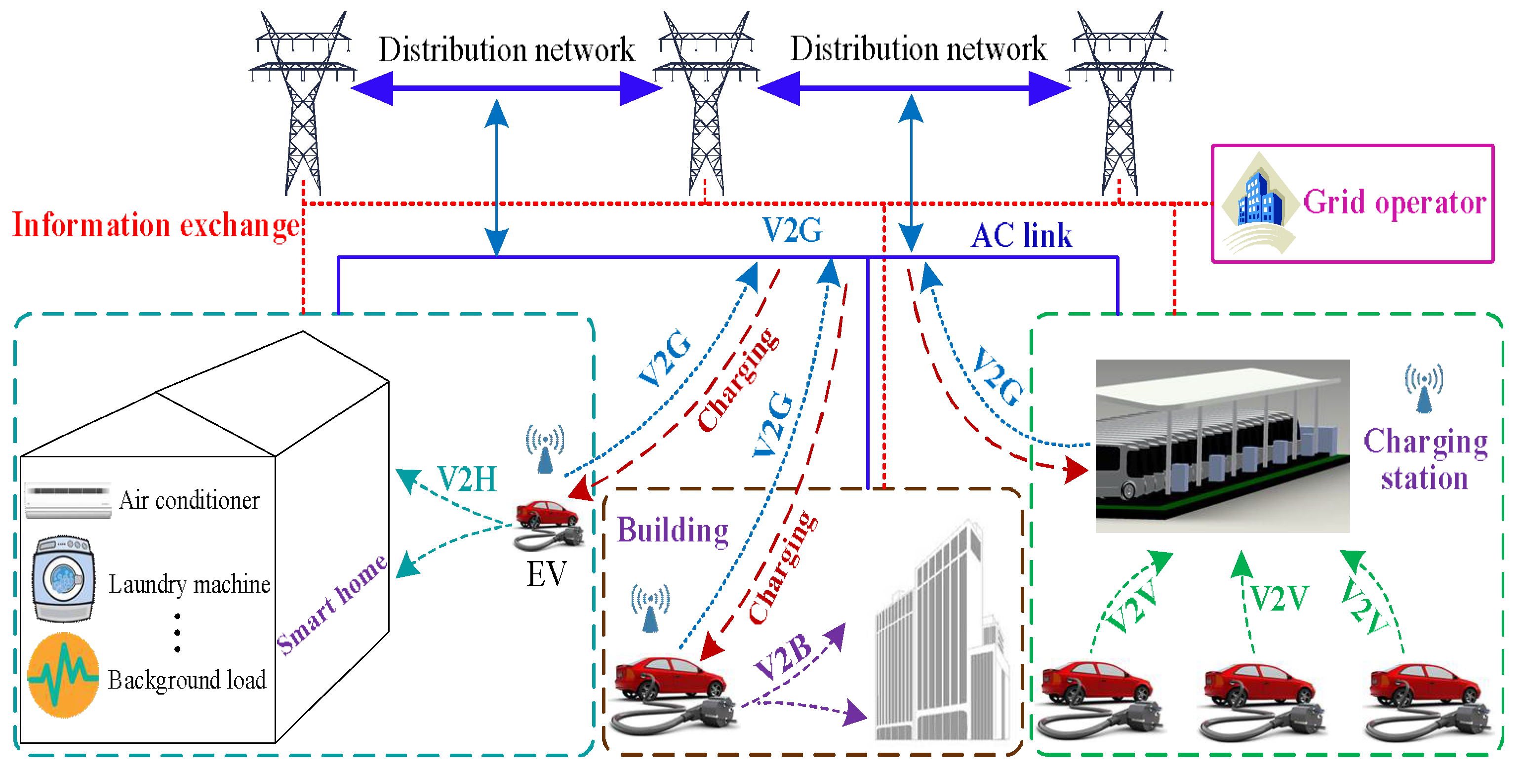
Due to the inherent mobility of vehicles, the charging activities of EV customers are hard to predict. EV owners can choose to park their cars in private garages when they return home, in their company charging places during weekdays, or in commercial parking stations for traveling purposes, to procure energy to refill EV batteries. When EVs are connected to the power grid, the power grid provides a channel for griddable EVs to perform ‘Grid-to-vehicle’ (G2V) charging. With the discharging capability enabled in the near future, EVs are also envisaged to perform various V2A activities, including V2H, V2B, V2V, and V2G. An overview of the V2A paradigm is given in Figure 1. The demonstrated architecture consists of a power grid operator, smart home, smart building, charging station, AC transmission link, communication channel, and other basic power system elements. EVs are parked in different places and can be controlled to perform various discharging activities, in detail: V2H for home usage, V2B for building energy management, V2V among different EVs in EV charging station, and V2G arranged in different places.
All the power consumption/supply units are supervised by the grid operator, which depends on the support of bidirectional communications. The details of the V2A charging mode are introduced below.
2.1. V2H Charging Scenario
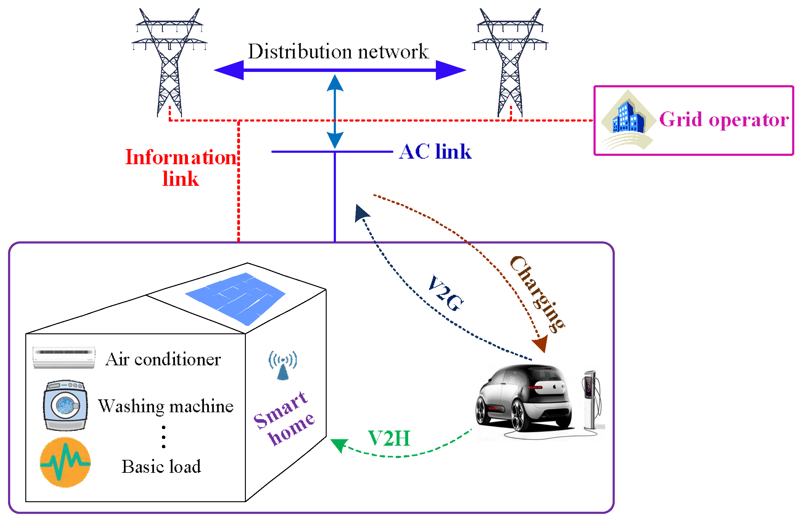
When an EV needs power refilling, the most convenient approach for EV users to recharge their cars is to connect EVs to home private charging piles. Meanwhile, it is assumed that EV and the other household appliances (e.g., air conditioner, washing machine, etc.) are all managed and controlled through a HEMS (Home Energy Management System). Under this condition, V2H can be operated. V2H refers to the power compensation from the EV battery to other home loads, e.g., air conditioner, washing machine, water heater, and so on, as shown in Figure 2. EV owners can choose to perform V2H in response to price variations; for instance, they can charge their cars when the power price is low and discharge their cars during high-price time slots. In this manner, EV users can achieve the goal of paying less for energy bills.
Generally, V2H endows EV with the following features: (1) V2H typically involves only one EV for a single house; (2) V2H can help reduce household power consumption bills; (3) V2H can smooth the daily load profile of a single family; (4) V2H can interact with the utilization of household distributed power resources, thus improving the energy efficiency of a house; (5) since a household is a basic unit for a gird, V2H can also enhance the development of the smart grid.
2.2. V2B Charging Scenario
V2B is defined as the energy transfer of EV battery to a building, e.g., a building located in a school or a company, for supporting its internal loads [9], as shown in Figure 3. Through V2B, the operation cost of the managed building can be lowered. Meanwhile, as a countermeasure, V2B can be arranged to mitigate the potential power mismatch between day-ahead scheduling energy demand and real-time power consumption [14].
EV users can perform V2B when they park their cars in a smart garage of a single building; this charging mode is attractive in several aspects: (1) V2B can help facilitate the participation of buildings in demand side management; to be more specific, it can reduce the on-peak load of buildings through load shifting operation; (2) V2B can be operated for emergency backup purposes, to generate power for power restoration of buildings when outage management is needed; (3) besides the energy regulation of buildings, V2B also provides extra profit for EV owners; (4) V2B is simpler than V2G, and is regarded as a more near-term alternative to V2G [9].
2.3. V2V Charging Scenario
V2V means the energy transaction among different EVs at an EV aggregator, an EV charging station, or a community [10,15]. In Figure 4, the V2V operation of an EV charging station is demonstrated. All EVs can interact with each other, controlled by the centralized controller deployed by the charging station. The charging station acts as an aggregator and is responsible for the group coordination of EV charging/discharging. The energy of EVs can be first distributed among each other, and then can be arranged to interact with the power grid for overall energy demand procurement.
Through the adoption of V2V, the power energy reserve within an aggregator or community can be maintained, which can offload the power demand from the power grid to the aggregated area. The application of V2V can bring the following benefits: (1) V2V can help coordinate the energy consumption within a community, thus facilitating the coordination of EVs and the power grid; (2) the execution of V2V involves very few power transmission losses; (3) with V2V operation, the charging efficiency of EVs can be greatly improved, while the power demand of a community can also be offloaded; (4) V2V can facilitate the utilization of renewable energy resources within a community grid and the development of the smart grid.
2.4. V2G Charging Scenario
V2G signifies the discharging power released from EVs to the power grid, as shown in Figure 5. The given framework consists of residential households, a battery swapping station, distributed renewable energy resources, an EV charging station, smart buildings, smart home, and other essential power grid elements. Based on practical applications and voltage levels, the energy distribution can be categorized into three clusters [10]: the first cluster performs charging/discharging for EVs at low-voltage networks such as at home or building parking lots; the second cluster implements EV charging/discharging at charging stations, particularly for fast power exchange of EVs at medium-voltage networks; the third cluster is EV batteries that are swapped at battery swapping stations while the discharged batteries are collectively recharged. It should be noted that the third role is not advised for V2G operation.
The discharging capability of a single EV, however, is normally limited due to its small capacity. To explore the full storage potential of V2G, a group of EVs is usually coordinated and governed through an internal agent, e.g., an EV charging station or an EV aggregator [16]. The EV user can choose an aggregator for V2G participation via signing a contract, while the aggregator can obtain regulation revenues through the incentives offered by the power operators. A thorough review of V2G can be found in [6] and the opportunities offered by V2G are briefly summarized below:
(1) V2G can be operated in various places, e.g., residential areas, commercial parking lots, and work places, as displayed in Figure 5; (2) with V2G participation of massive EVs, adequate power supply can be provided for a power regulation service; (3) V2G activity has the potential to improve the power stability, energy efficiency, and reliability of power grids; (4) V2G can be arranged to coordinate with distributed renewable energy resources; (5) V2G is considered an important element for the realization of smart grid.
The above activities constitute the paradigm of the V2A charging mode. Based on the above introduction, a single EV can perform different activities depending on the parking places, normally: (1) G2V, V2H, and V2G at home; (2) G2V, V2B, and V2G in building garages; (3) G2V, V2V, and V2G at a commercial charging station.
3. Modeling for V2A Charging Mode
The aim of this paper is to develop a generic model that can support the various charging activities of V2A applications. Therefore, all the charging statuses, including charging, V2H/V2B/V2V, and V2G should be determined at each timeslot. Meanwhile, for the development of the proposed model, the following assumptions are used: (1) The EV vehicles studied are pure EVs; (2) reactive power exchange is not considered at the current stage; (3) the price for EV charging and other loads is different from the V2G power price for incentive purposes [17], i.e., the power load price ϑL,t and the V2G power price ϑV2G,t are two different price signals; (4) the charging/discharging power is assumed to be the rated power of the EV battery.
In addition, EV charging decisions must be given on the basis of predefined objectives. In this work, the power consumers are supposed to be price followers, i.e., EVs or the load consumption unit would make decisions about EV charging in response to price signals released by power system operators.
3.1. Constraints
Other than charging for a whole day, an EV usually completes its power refilling within a certain period, while its charging/discharging should be subject to constraints from both user power demand and battery technical limitations:
(1) Constraint of battery SOC (State-of-charge)
(2) Energy requirement from EV user
The charging activity of a single EV during its charging period should satisfy the energy desire of the EV user for traveling purposes:
(3) Constraint for EV charging statuses
The charging and discharging of an EV cannot contradict each other. Namely, at each time slot, EV should be idling, charging, or in one of the V2A discharging activities, i.e.,
(4) Consideration of the lifetime of the EV battery
To prolong the lifetime of the EV battery, the charging degradation should also be considered, and it can be quantified through EV charging/discharging cycles [19]:
where denotes the discharging status of the ith EV.
(5) Constraint for special charging conditions
Under the condition of V2V charging scenario, the number of EVs transferring energy to other vehicles must be equal to the number of EVs procuring energy from other cars. This indicates that the number of EVs performing the charging activity should be no less than the number of EVs performing the V2V activity at each timeslot, i.e.,
3.2. Objective Function
The optimization goal for EV charging is to minimize the running costs of a power consumption unit (i.e., a home or a building), or maximize the profit of a power operation unit (e.g., an EV aggregator). The objective function of the above target can be given as:
For the final EV charging state limited by the energy desire from EV users, the constraint Equation (4) can be added to Equation (9) with an additional penalty function; the consideration Equation (6) for EV battery life can be also handled with the above method [17,19]. Then the objective function changes to:
where ρi denotes the penalty coefficient for EV charging satisfaction quantified through the deviation of final SOC state from the desired SOC; λi represents the penalty coefficient for EV battery degradation quantified through EV charging/discharging cycles.
In addition, the following limit should be guaranteed to ensure that the discharging power of V2H, V2B and V2V will not pour into the power grid:
3.3. Problem Transformation and Solving Method
For the above EV charging model, only the charging and discharging statuses are waiting to be solved. Therefore, the charging/discharging statuses are assigned as variables, with five Boolean state vectors attributed to the charging, V2H, V2B, V2V, and V2G statuses, respectively, for a single EV. Meanwhile, the constraints for EV charging are nonlinear. Based on existing studies, the proposed model can be transformed into the INLP (Integer Nonlinear Programming) optimization form [20,21], which can be expressed as:
where represents the objective goal; denotes the equal constraints constrained by the value set ; signifies the unequal constraints with limit set ; and denote the bounded lower and upper box constraints for ; and vector should be subject to integer space Z.
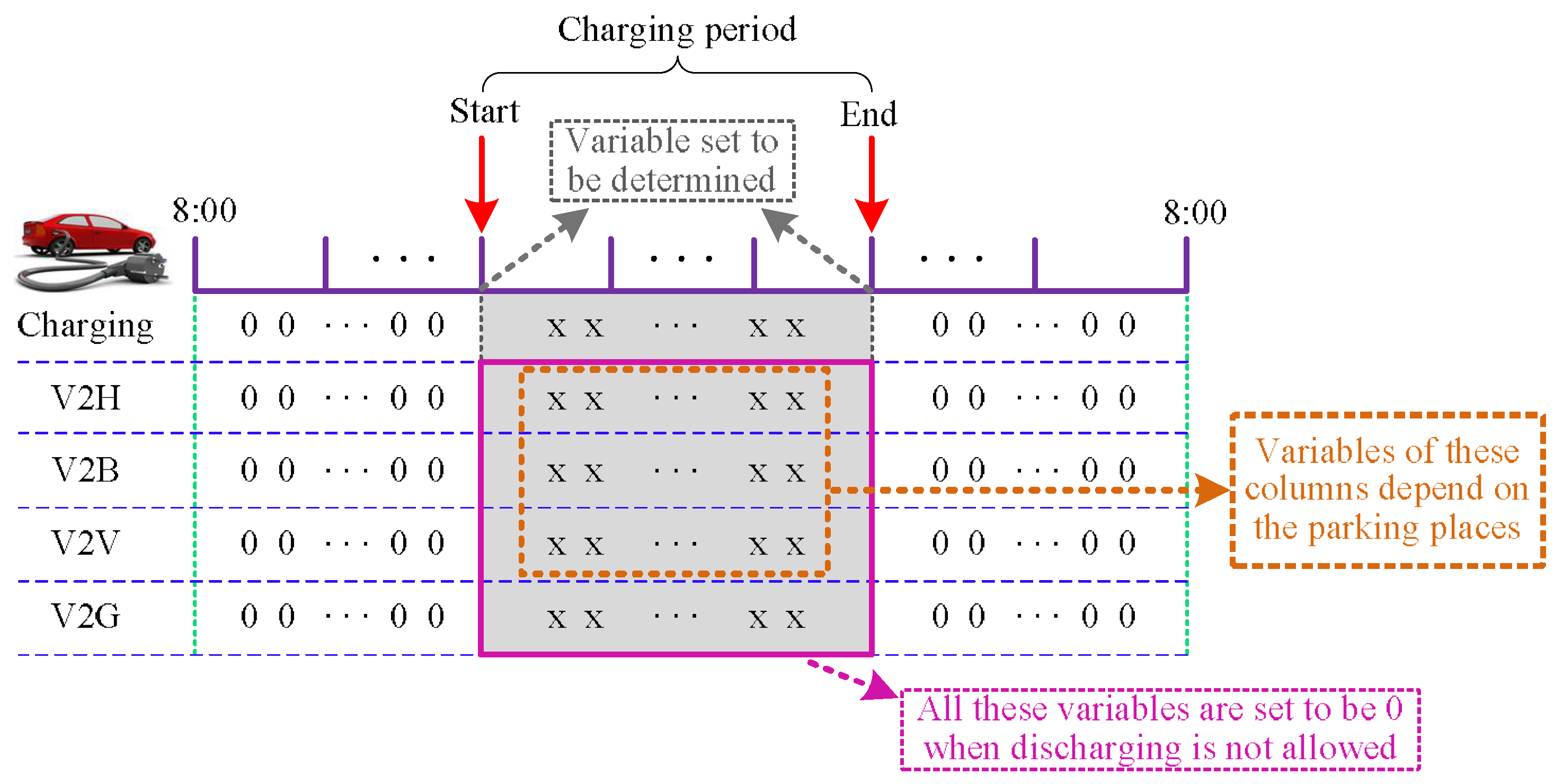
Taking all five Boolean state vectors into account, the computational effort for the INLP model would be enormous. For example, there would be 5 × 24 variables for a single EV. To ease the calculation burden, the variables for an EV can be preprocessed at the initialization stage. The control signals outside the EV charging period can be set to 0 to reduce the solved variables, as shown in Figure 6. Moreover, some variables can be predetermined based on practical charging scenarios. Specifically, all the discharging variables can be set to 0 when discharging activity is forbidden, while the state variables for V2H, V2B, and V2V can be partially determined based on the charging places discussed in Section 2.
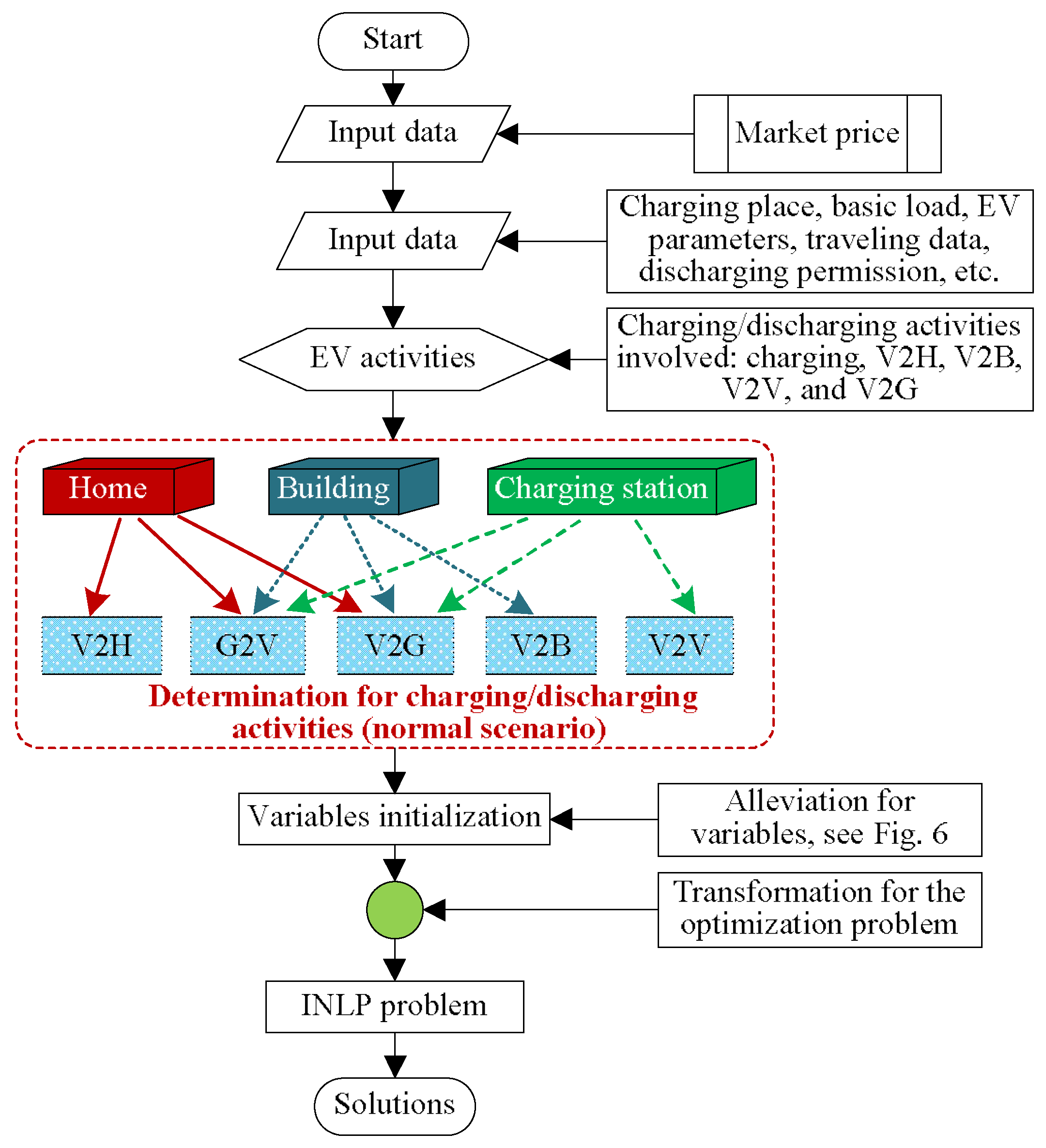
Since there are different charging places involved, an intelligent module is designed to guide the optimization for different applications of V2A, as displayed in Figure 7. The datasets including market prices, parking places, EV data, preference for charging/discharging activities in the charging location, and other essential information are collected at the initial stage. Based on the data obtained, the charging and V2A choices are determined, and the optimization problem is transformed into an INLP model, which will then be solved to finalize the solutions of charging/discharging statuses for the penetrated EV(s). It should be noted that the combinations of charging/discharging behaviors for different occasions can be adjusted based on practical demands.
The EV scheduling problem can be solved through many kinds of algorithms and tools; in this work, the optimization tool CVX [22] is utilized to work out the solutions of EV charging.
4. Simulation Cases
In this work, the model of V2A is given, which includes four discharging activities: V2H, V2B, V2V, and V2G. For illustration, the charging cases for a household, a building, and a commercial parking station are presented. The proposed charging model is coded and studied on a MATLAB platform.
4.1. Basic Parameters
The EVs simulated are supposed to be private vehicles with unified capacity of 24 kWh and nominal charging power of 3.3 kW. The charging and discharging efficiency are all set to 0.98. Furthermore, as EV users may arrive and depart the charging piles at random times, their charging behaviors should be predicted. Based on existing studies, the charging pattern of EVs can be captured through some stochastic methods [23,24]. In this work, Truncated Gaussian Distribution [23,24] is used to simulate the charging activities of EV customers, with the ranges of initial and expected SOC values given in Table 1. Moreover, for the household case, the EV charging is assumed to be performed during the night due to home user working/living habits [8]; for the building and charging station scenarios, EVs are supposed to park during the daytime, with ranges of plugging-in and unplugging times displayed in Table 1. In addition, the penalty coefficients ρi and λi are uniformly set to 1.5 and 0.15 for the test cases in Section 4.2 to Section 4.4. For the evaluation of battery degradation, Section 4.5 is given to simulate the influences of penalty coefficients ρi and λi on EV charging/discharging.
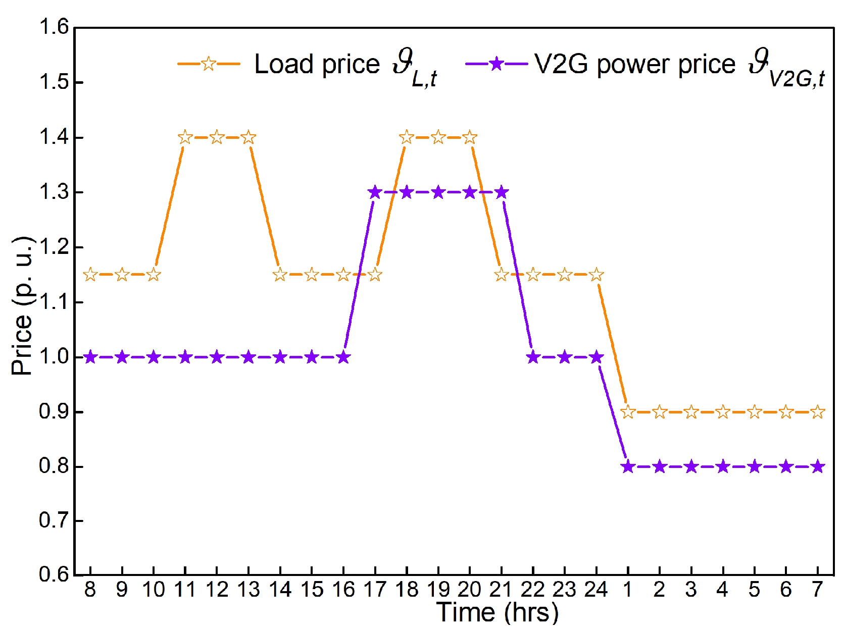
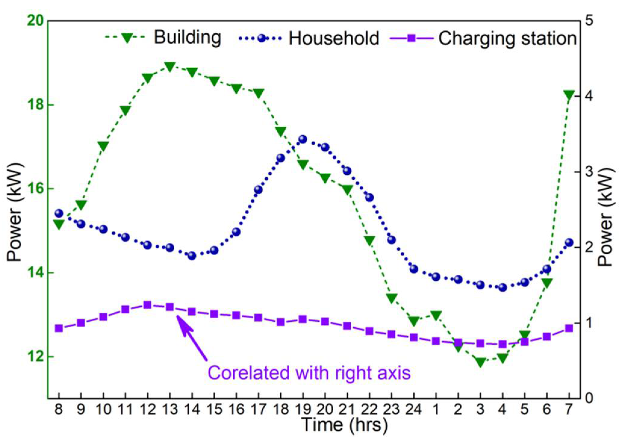
The simulated EV numbers for the test building and charging station are set at 5 and 10, respectively. The test signals for the power load price ϑL,t and the V2G power price ϑV2G,t are given in Figure 8. As stated before, the two price signals are differentiated for incentive purposes of EV charging/discharging activity in response to power load profiles [17]. Meanwhile, the two price vectors are just presupposed for testing purpose, which means the prices are fixed values. As can be seen, there are two high-power price periods (11:00–13:00 and 18:00–20:00) for ϑL,t to mitigate the morning and evening peak loads; there is one period (17:00–21:00) with high ϑV2G,t to motivate EV discharging since the power demand in the evening can be heavy due to increased residential loads (cooking, lighting, air conditioning, etc. when people return home after work) [25]. In addition, the basic loads for the household, the building, and the charging station are presented in Figure 9.
4.2. Simulation Results for the Household
The optimization goal for the EV charging of a household is to optimize the energy management so that the electricity cost of the home user can be minimized. The EV is set to plug into the power grid during the night when the EV user returns home. For comparison, a scenario where discharging of the EV is not allowed is also simulated. The simulation outcome for the household is given in Figure 10.
According to the results, for the case of EV charging with discharging ability permitted, in response to the price signals, the EV is arranged to perform charging for power refilling during lower price timeslots (i.e., 16:00–17:00, and 2:00–4:00) while choose to discharge for V2G when the V2G price is attractive (at 21:00) and perform V2H when the load price is high (during the time period 18:00–20:00). This demonstrates EV charging/discharging is smartly regulated based on the price tuples. In addition, the power consumption costs for the household are 101.09 p. u. and 105.71 p. u., respectively, with and without EV discharging, indicating a reduction of 4.37% in energy expense with V2A enabled. This proves that the discharging activity can help minimize the overall power consumption cost of the household.
The energy state for the EV battery is demonstrated in Figure 11. As demonstrated, the energy desire of the home user is well achieved without SOC bound violations. The above outcome indicates that the charging model can smartly support EV charging/discharging activities for home usage.
4.3. Simulation Results for the Building
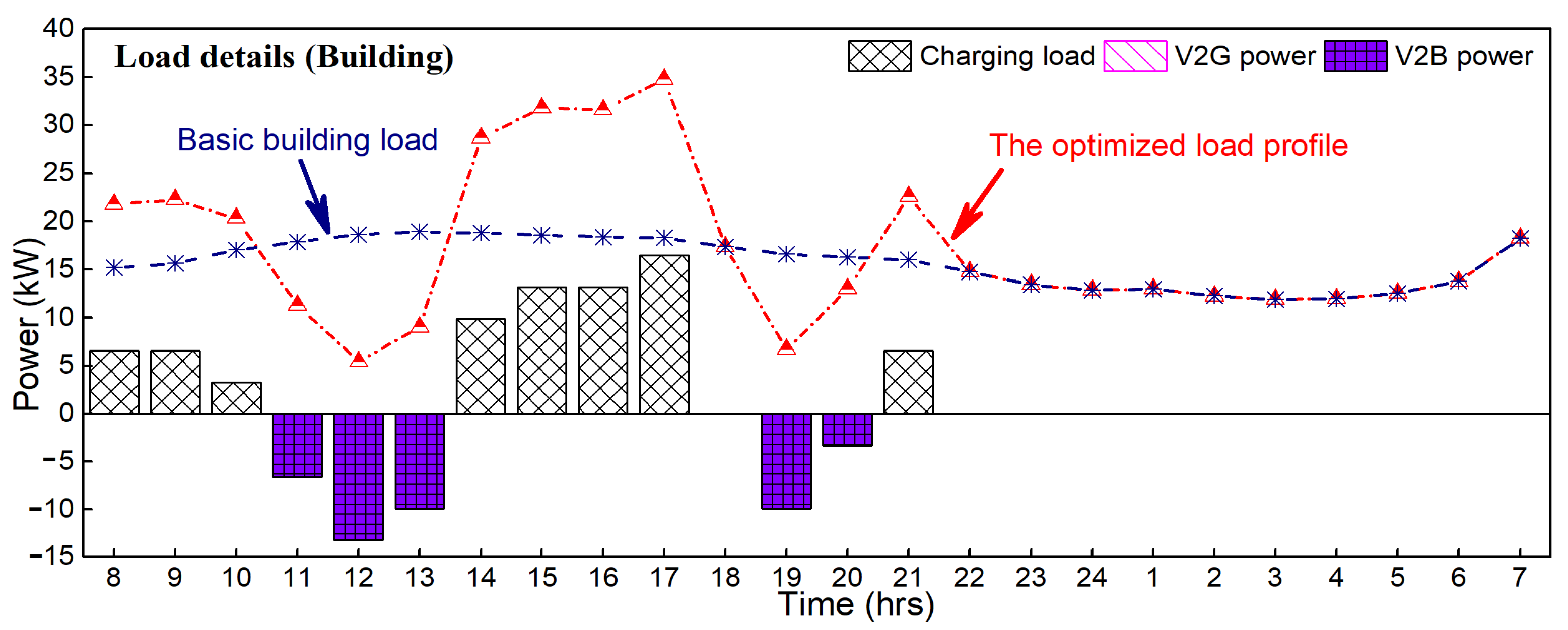
The simulation outcome for EV management of the building is given in Figure 12. As presented, EVs are managed to perform V2B activity to compensate for the daily load of the building at the time slots 11:00–13:00 and 19:00–20:00. It is also observed that no V2G activity is organized during the simulated time window. The reason is that the load profile of the building during the daily time when EVs are connected is apparently high. Therefore, in response to the price signals, the prior choice for the building is to perform V2B activity to lower the load consumption for the reduction of the overall power energy cost. This indicates that the charging model can also effectively support the EV charging/discharging decisions for EVs parked in a building.
4.4. Simulation Results for the EV Charging Station
The simulation outcome for EV management of the EV charging station is given in Figure 13. As demonstrated, some of the parked EVs are operated to perform V2V activity at 11:00–13:00 to support the charging demand of other EVs before their departure from the charging station. With this operation, the power energy cost can be reduced since the power prices during 11:00–13:00 are the highest during the whole day. Moreover, one of the EVs is managed to deliver its battery energy to the grid (V2G) at 18:00 when the V2G price provided is attractive. This indicates that the proposed model can also meet the regulation demand of charging, V2V, and V2G for an EV charging station in response to price signals.
4.5. Consideration for the Issue of Battery Degradation
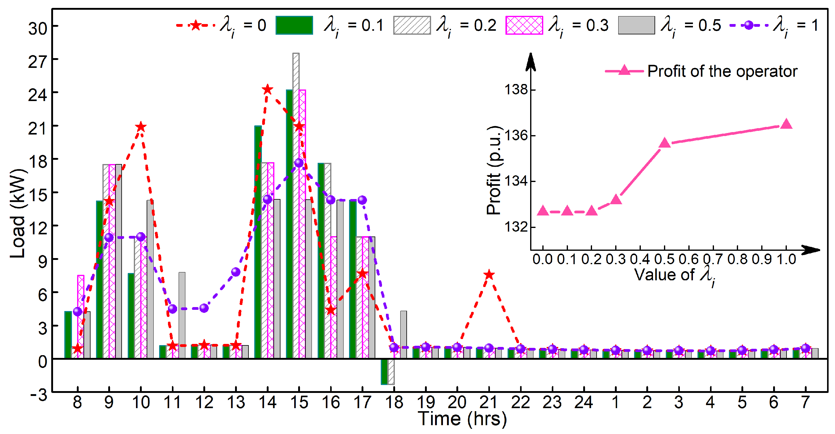
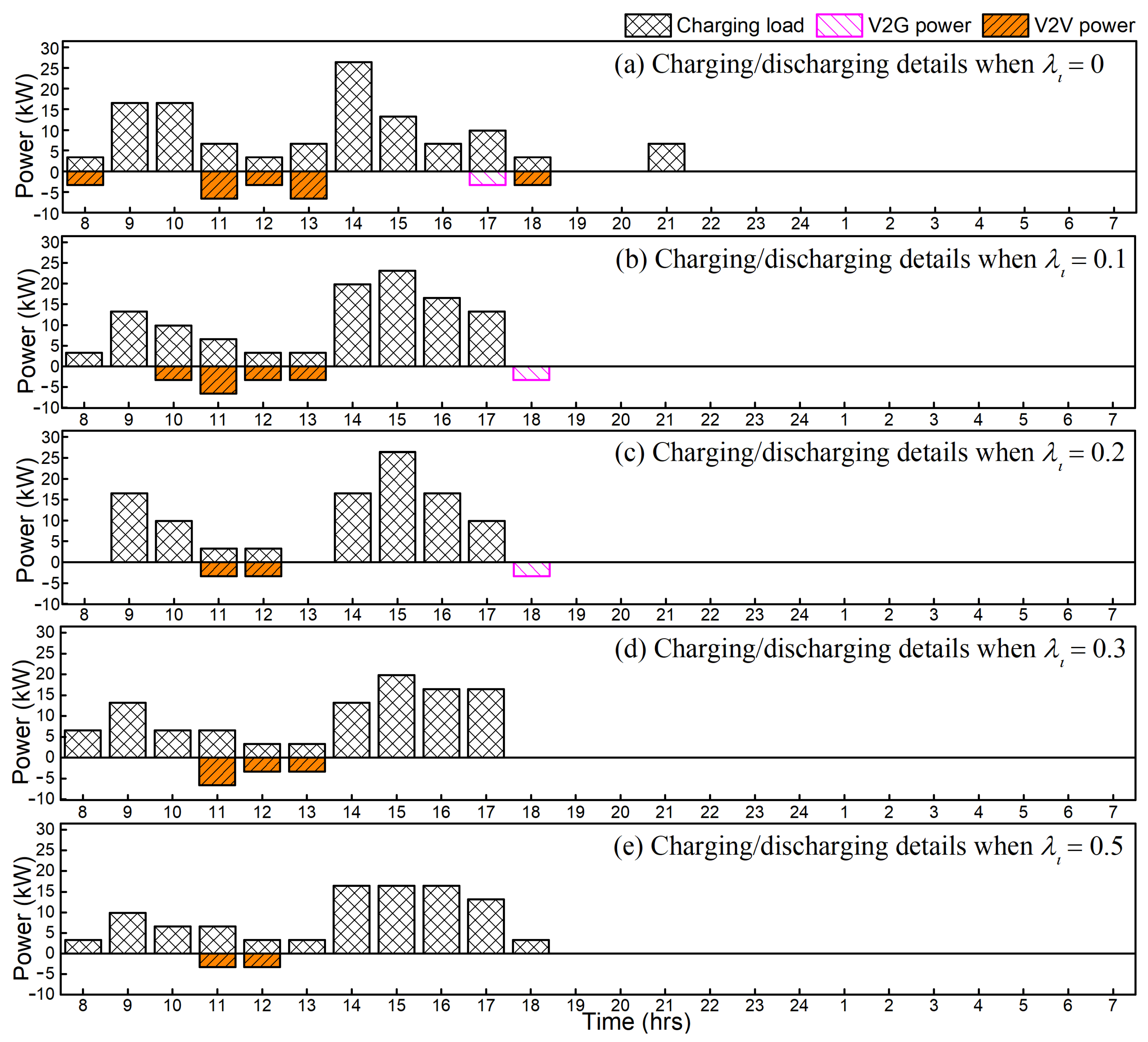
As modeled in Equations (6) and (10), the issue of battery degradation is quantified through the evaluation of EV charging/discharging cycles. The values of penalty coefficient for the charging cycles of EVs are therefore simulated to investigate the influence of battery degradation. For convenience, the values of λi are uniformly set for all EVs. The charging scenario of the EV charging station is analyzed with different λi and the simulation outcome including the total load and economic profit for the operator side is presented in Figure 14. The charging/discharging behaviors of EVs are given in Figure 15. Since no EV selects discharging under the case , the details of EV behaviors for this scenario are therefore omitted here.
As can be seen from Figure 15, with the increase of λi, EVs choose to perform less discharging due to the increased penalty for battery charging/discharging cycles. The users smartly choose to perform charging or discharging at adjacent time slots when λi increases, or even give up discharging when . Based on Figure 14, the load profile tends to fluctuate more when λi decreases, while the power consumption cost changes to be higher when the demand for the lifecycle of EV batteries changes is higher (i.e., with higher λi). The battery degradation is therefore an important concern that can affect the charging/discharging behavior of EVs and the operational costs of the power consumption entity.
5. Conclusions
A generic model that can fit the various activities of V2A application has been presented in this paper. With the proposed model, the decisions of charging/discharging statuses including charging, V2H, V2B, V2V, and V2G of EVs under the guidance of power price signals for different parking places can be supported. The battery degradation issue has also been considered. As demonstrated by the simulation results, the proposed model can be utilized to help minimize the power energy cost of the power consumption entity or community involved with V2A applications in response to the price signals released by the grid operator. For instance, a reduction of 4.37% in energy expenses can be achieved in a case study with EV discharging enabled for a household. This also reflects that EVs are prone to perform less discharging when the demand for the lifecycle of EV batteries is higher. Since power prices can induce different charging/discharging behaviors in EVs, future work should be focused on price tuning for regulating EV charging/discharging behaviors. The constraints of power grids can also be studied to fit the proposed model into more practical applications.
Author Contributions
T.M. conducted the investigation, designed the methodology and completed the original draft; X.Z. and B.Z. gave suggestions on the proposed idea and simulation cases; T.M. and X.Z. revised the paper based on comments from the reviewers; T.M. checked the proofreading.
Acknowledgments
This paper was supported by the project “Research on power system planning theory with high proportion of intermittent renewable energy resources” of the China Southern Power Grid (CSGTRC-K163007).
Conflicts of Interest
The authors declare no conflict of interest.
Nomenclature
| t | Time index |
| i | EV index |
| ST | Time interval set |
| SE | EV set at a power consumption unit |
| Lower SOC limit for the ith EV | |
| Upper SOC limit for the ith EV | |
| SOC state of the ith EV at time t | |
| SOC value at plugging-in time of ith EV | |
| SOC value at plugging-out time of ith EV | |
| Expected SOC value of ith EV from the car owner | |
| Nominal battery SOC of the ith EV | |
| Nominal charging power of the ith EV | |
| Battery capacity of the ith EV | |
| Charging efficiency of the ith EV | |
| Discharging efficiency of the ith EV | |
| Charging status (0 or 1) at time t of the ith EV | |
| V2H status (0 or 1) at time t of the ith EV | |
| V2B status (0 or 1) at time t of the ith EV | |
| V2V status (0 or 1) at time t of the ith EV | |
| V2G status (0 or 1) at time t of the ith EV | |
| tstart | Charging start time |
| tend | Charging end time |
| Working period of the ith EV | |
| TB | Time period of basic load for a power consumption unit |
| Basic power load at time t for a power consumption unit | |
| ϑV2G,t | V2G power price at time t |
| ϑL,t | Power load price at time t |
| ρi | Penalty coefficient for energy desire of the ith EV |
| λi | Penalty coefficient for charging cycles of the ith EV |
References
- Tesla Motors: ‘Tesla Motors—High Performance Electric Vehicles’. 2010. Available online: http://www.teslamotors.com/ (accessed on 15 June 2010).
- Sikes, K.; Gross, T.; Lin, Z.; Sullivan, J.; Cleary, T.; Ward, J. Plug-In Hybrid Electric Vehicle Market Introduction Study: Final Report; Tech. Rep. DE2010-972306; U.S. Department of Energy: Washington, DC, USA, 2010.
- International Energy Agency: ‘Global EV Outlook 2017’. 2017. Available online: https://www.iea.org/publications/freepublications/publication/global-ev-outlook-2017.html (accessed on 6 June 2017).
- De Quevedo, P.M.; Muñoz-Delgado, G.; Contreras, J. Impact of electric vehicles on the expansion planning of distribution systems considering renewable energy, storage and charging stations. IEEE Trans. Smart Grid 2017. [Google Scholar] [CrossRef]
- Tang, D.; Wang, P. Nodal impact assessment and alleviation of moving electric vehicle loads: From traffic flow to power flow. IEEE Trans. Power Syst. 2016, 31, 4231–4242. [Google Scholar] [CrossRef]
- Yilmaz, M.; Krein, P.T. Review of the impact of vehicle-to-grid technologies on distribution systems and utility interfaces. IEEE Trans. Power Electr. 2013, 28, 5673–5689. [Google Scholar] [CrossRef]
- Un-Noor, F.; Padmanaban, S.; Mihet-Popa, L.; Mollah, M.N.; Hossain, E. A comprehensive study of key electric vehicle (EV) components, technologies, challenges, impacts, and future direction of development. Energies 2017, 10, 1217. [Google Scholar] [CrossRef]
- Nguyen, D.T.; Le, L.B. Joint optimization of electric vehicle and home energy scheduling considering user comfort preference. IEEE Trans. Smart Grid 2014, 5, 188–199. [Google Scholar] [CrossRef]
- Pang, C.; Dutta, P.; Kezunovic, M. BEVs/PHEVs as dispersed energy storage for V2B uses in the smart grid. IEEE Trans. Smart Grid 2012, 3, 473–482. [Google Scholar] [CrossRef]
- Liu, C.; Chau, K.T.; Wu, D.; Gao, S. Opportunities and challenges of vehicle-to-home, vehicle-to-vehicle, and vehicle-to-grid technologies. Proc. IEEE 2013, 101, 2409–2427. [Google Scholar] [CrossRef] [Green Version]
- Abboud, K.; Omar, H.; Zhuang, W. Interworking of DSRC and cellular network technologies for V2X communications: A Survey. IEEE Trans. Veh. Technol. 2016, 65, 9457–9470. [Google Scholar] [CrossRef]
- Zheng, K.; Zheng, Q.; Chatzimisios, P.; Xiang, W.; Zhou, Y. Heterogeneous vehicular networking: A survey on architecture, challenges, and solutions. IEEE Commun. Surv. Tutor. 2015, 17, 2377–2396. [Google Scholar] [CrossRef]
- Ferreira, J.C.; Monteiro, V.; Afonso, J.L. Vehicle-to-Anything Application (V2Anything App) for Electric Vehicles. IEEE Trans. Ind. Inform. 2014, 10, 1927–1937. [Google Scholar] [CrossRef] [Green Version]
- Wu, D.; Zeng, H.; Lu, C.; Boulet, B. Two-stage energy management for office buildings with workplace EV charging and renewable energy. IEEE Trans. Transp. Electr. 2017, 3, 225–237. [Google Scholar] [CrossRef]
- Wang, M.; Ismail, M.; Zhang, R.; Shen, X.; Serpedinz, E.; Qaraqey, K. A semi-distributed V2V fast charging strategies based on price control. In Proceedings of the IEEE GLOBECOM, Austin, TX, USA, 8–12 December 2014; pp. 4550–4555. [Google Scholar]
- Ortega-Vazquez, M.A.; Bouffard, F.; Silva, V. Electric vehicle aggregator/system operator coordination for charging scheduling and services procurement. IEEE Trans. Power Syst. 2013, 28, 1806–1815. [Google Scholar] [CrossRef]
- Mao, T.; Lau, W.H.; Shum, C.; Chung, H.S.H.; Tsang, F.K.; Tse, N.C.F. A regulation policy of EV discharging price for demand scheduling. IEEE Trans. Power Syst. 2018, 33, 1275–1288. [Google Scholar] [CrossRef]
- Charging Lithium-IoN. Available online: http://batteryuniversity.com (accessed on 9 May 2017).
- Yifeng, H.; Venkatesh, B.; Ling, G. Optimal scheduling for charging and discharging of electric vehicles. IEEE Trans. Smart Grid 2012, 3, 1095–1105. [Google Scholar]
- Esmaili, M.; Rajabi, M. Optimal charging of plug-in electric vehicles observing power grid constraints. IET Gener. Transm. Distrib. 2014, 8, 583–590. [Google Scholar] [CrossRef]
- Tsui, K.M.; Chan, S.C. Demand response optimization for smart home scheduling under real-time pricing. IEEE Trans. Smart Grid 2012, 3, 1812–1821. [Google Scholar] [CrossRef]
- Michael, G.; Stephen, B. CVX: Matlab Software for Disciplined Convex Programming. Available online: http://cvxr.com/cvx (accessed on 4 September 2012).
- USA: “Summary of Travel Trends: 2009 National Household Travel Survey”, Federal Highway Administration. Available online: http://nhts.ornl.gov/2009/pub/stt.pdf (accessed on 10 August 2012).
- Shafie-khah, M.; Heydarian-Forushani, E.; Osório, G.J.; Gil, F.A.S.; Aghaei, J.; Barani, M.; Catalão, J.P.S. Optimal behavior of electric vehicle parking lots as demand response aggregation agents. IEEE Trans. Smart Grid 2016, 7, 2654–2665. [Google Scholar] [CrossRef]
- Leou, R.C. Optimal charging/discharging control for electric vehicles considering power system constraints and operation costs. IEEE Trans. Power Syst. 2016, 31, 1854–1860. [Google Scholar] [CrossRef]
Figure 1.
Overview of V2A paradigm.

Figure 2.
Paradigm of V2H.

Figure 3.
Paradigm of V2B.
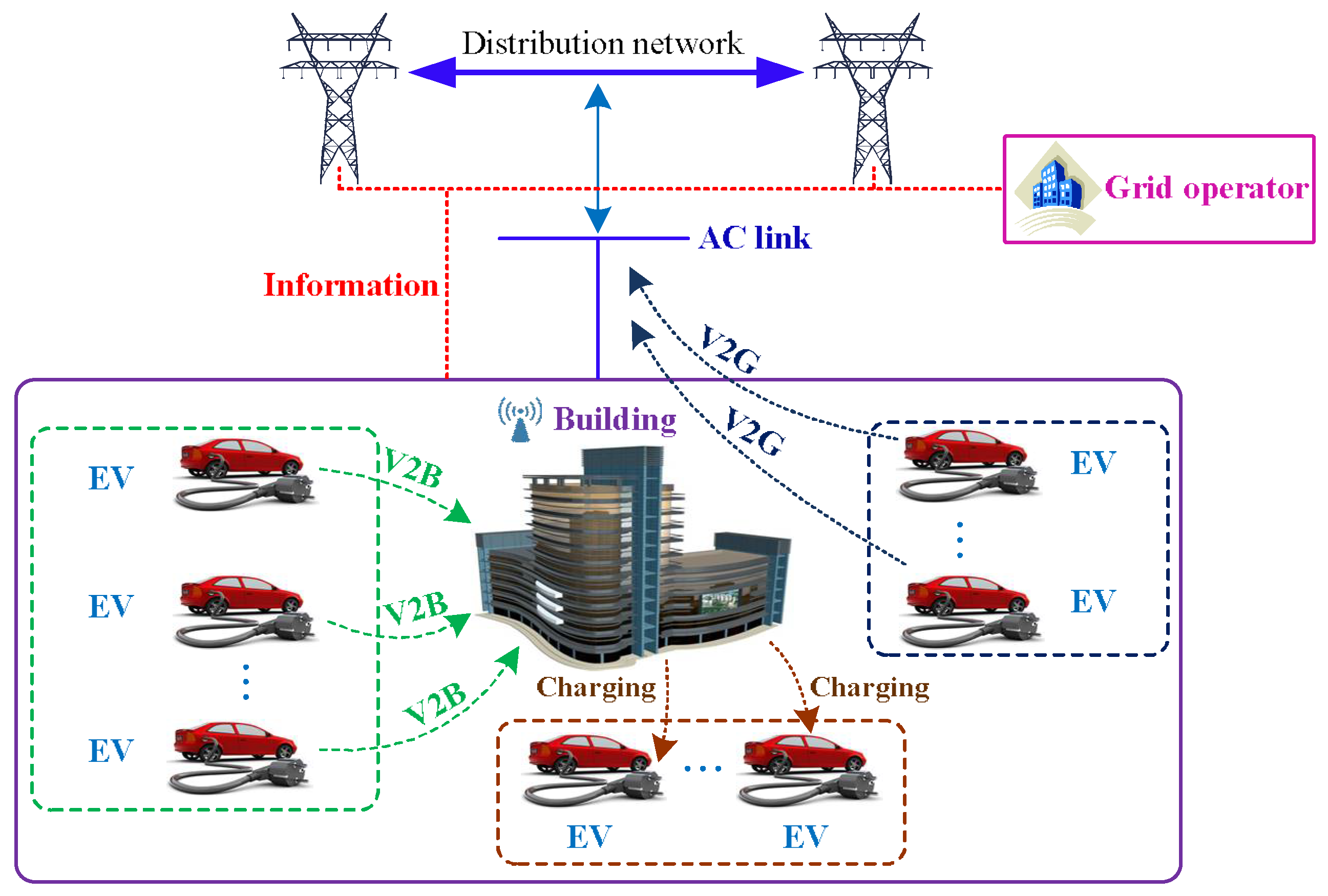
Figure 4.
Paradigm of V2V.
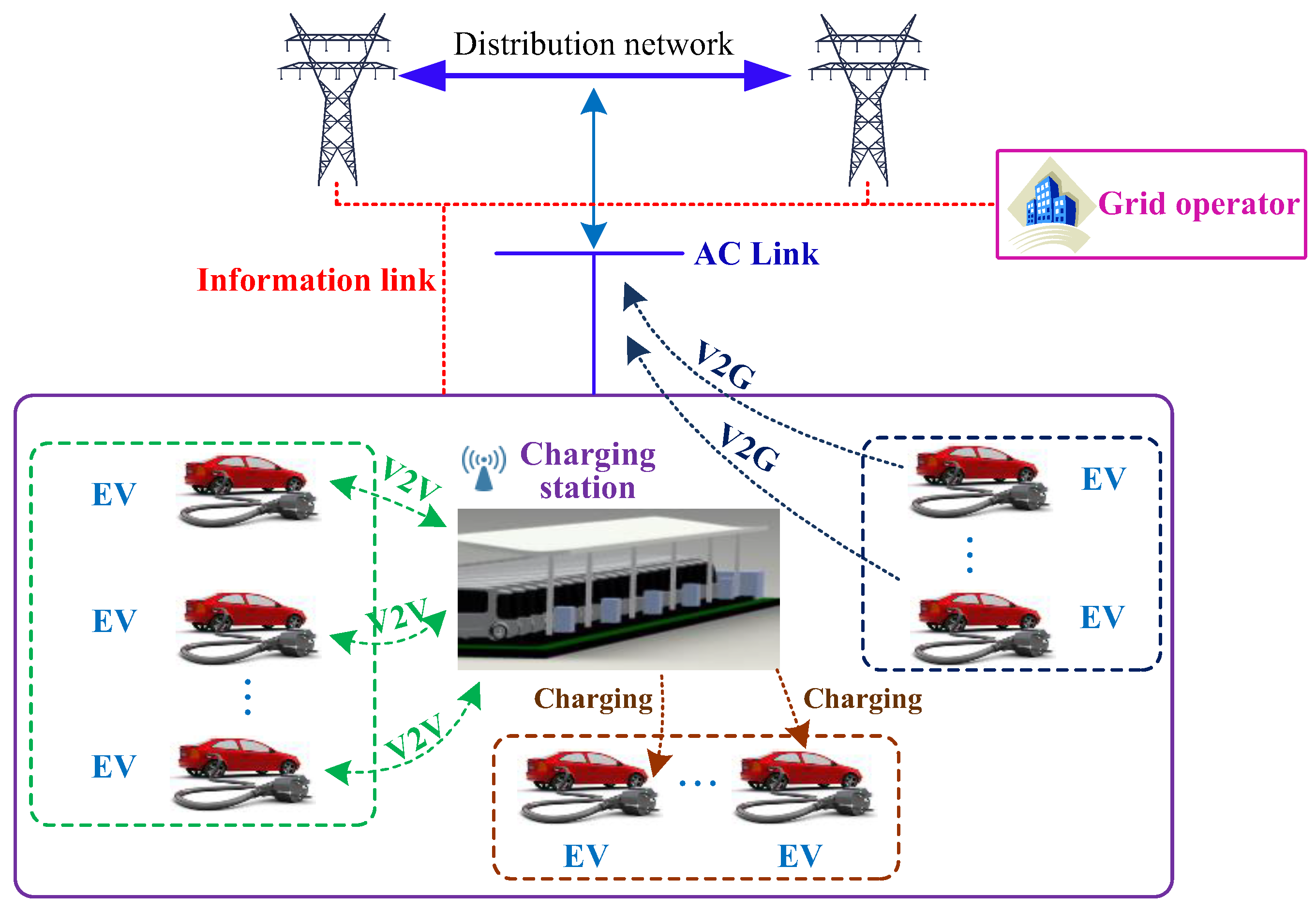
Figure 5.
Paradigm of V2G.
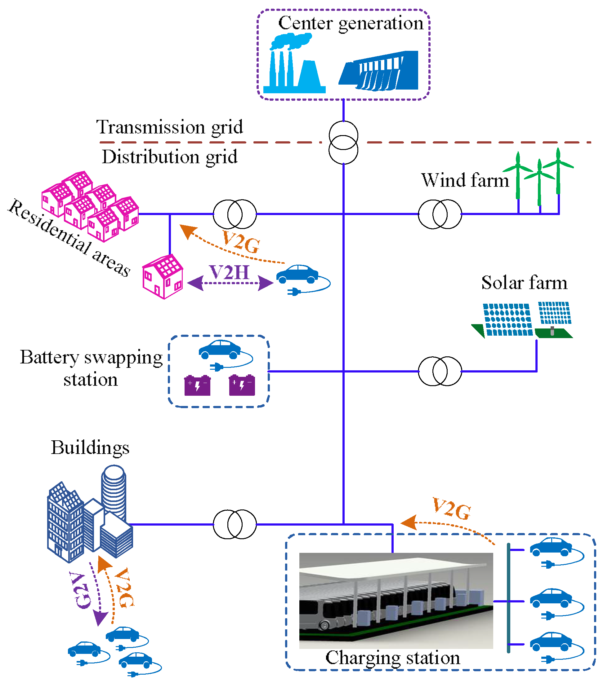
Figure 6.
Treatment for control variables of a single EV.

Figure 7.
Optimization process for different V2A applications.

Figure 8.
Price signals for simulation.

Figure 9.
Basic load profiles for simulation: left axis for the building and household load; right axis for the charging station load.
Figure 9.
Basic load profiles for simulation: left axis for the building and household load; right axis for the charging station load.

Figure 10.
Outcome for the EV management of the household: (a) load details with discharging; (b) load details without discharging; basic household load refers to the household load without EV load profile; the optimized load profile refers to the basic household load plus the aggregated EV charging/discharging result based on the proposed model.
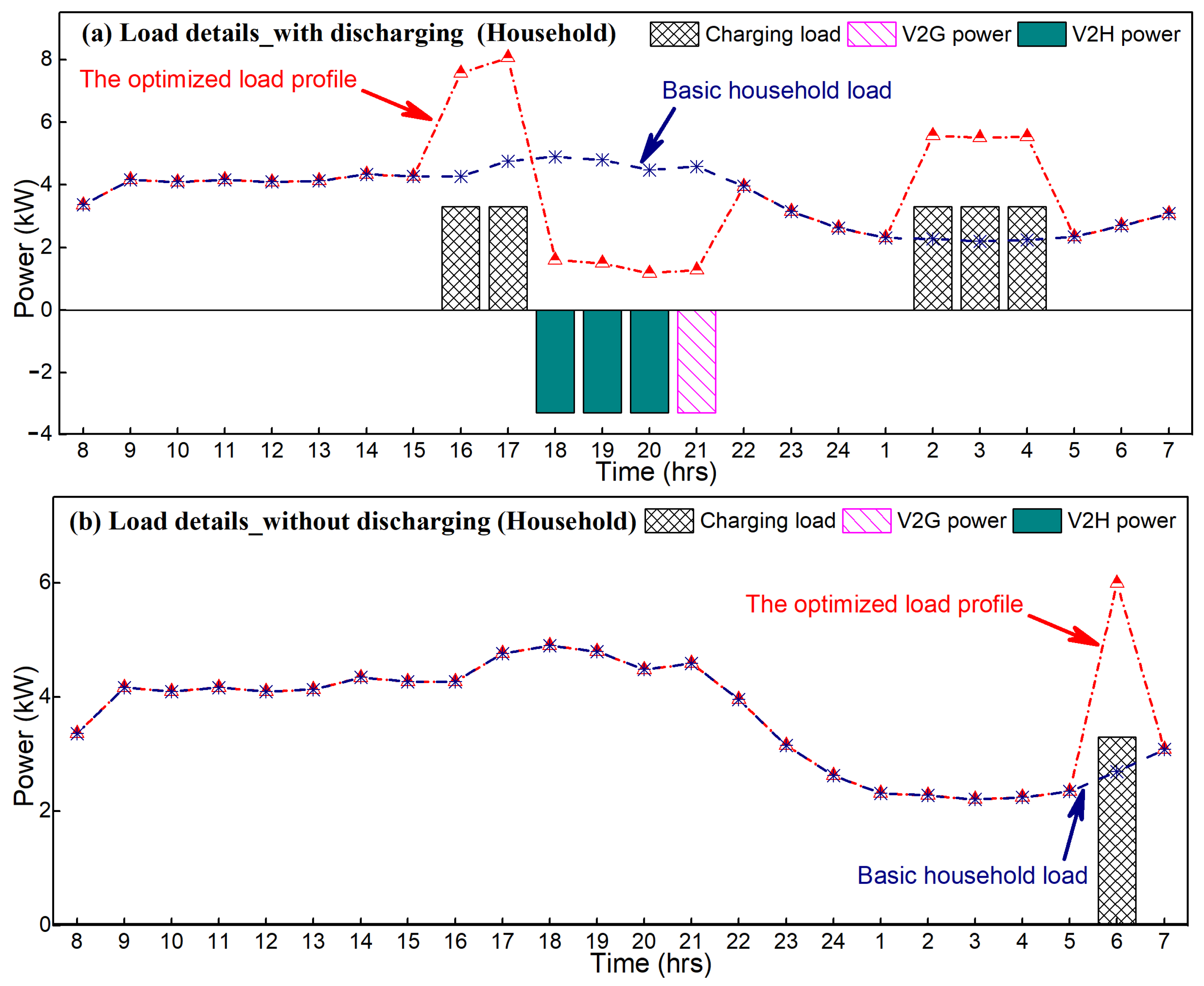
Figure 11.
Energy state of the managed EV.
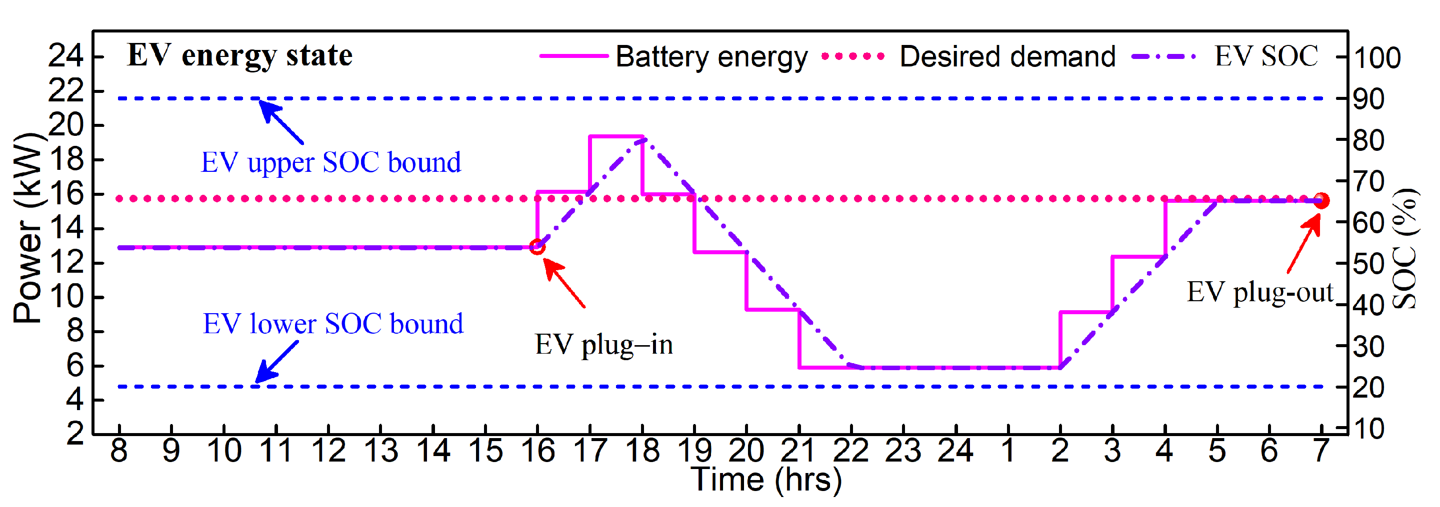
Figure 12.
Outcome for EV charging of the building: basic building load refers to the building load without EV load profile; the optimized load profile refers to the basic building load plus the aggregated EV charging/discharging result based on the proposed model.
Figure 12.
Outcome for EV charging of the building: basic building load refers to the building load without EV load profile; the optimized load profile refers to the basic building load plus the aggregated EV charging/discharging result based on the proposed model.

Figure 13.
Outcome for EV charging of the charging station: basic charging station load refers to the charging station load without EV load profile; the optimized load profile refers to the basic charging station load plus the aggregated EV charging/discharging result based on the proposed model.
Figure 13.
Outcome for EV charging of the charging station: basic charging station load refers to the charging station load without EV load profile; the optimized load profile refers to the basic charging station load plus the aggregated EV charging/discharging result based on the proposed model.
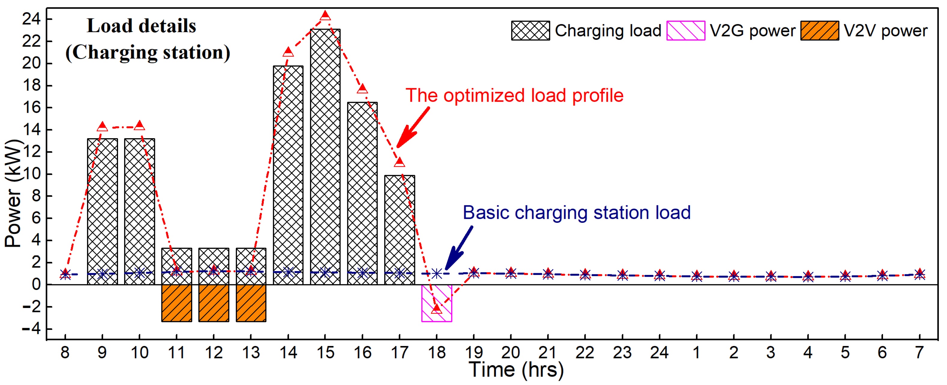
Figure 14.
Simulation results of the charging station with different λi: the load profiles in the big frame demonstrate the load curve changes to be more fluctuate with the increase of λi; the profit of the operator in the small frame indicates the profit can be improved with the increase of λi.
Figure 14.
Simulation results of the charging station with different λi: the load profiles in the big frame demonstrate the load curve changes to be more fluctuate with the increase of λi; the profit of the operator in the small frame indicates the profit can be improved with the increase of λi.

Figure 15.
Details of the aggregated EV charging/discharging profiles for the charging station with different λi: (a–e): λi = 0, 0.1, 0.2, 0.3 and 0.5 respectively; with the increase of λi, EVs choose to perform less discharging.
Figure 15.
Details of the aggregated EV charging/discharging profiles for the charging station with different λi: (a–e): λi = 0, 0.1, 0.2, 0.3 and 0.5 respectively; with the increase of λi, EVs choose to perform less discharging.


Table 1.
Simulation parameters.
| Parameter | Value | Parameter | Value |
|---|---|---|---|
| tstart range of EV | [8:00, 15:00] | 0.9 | |
| tend range of EV | [13:00, 22:00] | (kW) | 3.3 |
| (range) | [0.2, 0.65] | (kWh) | 24 |
| (range) | [0.6, 0.95] | 0.98 | |
| 0.2 | 0.98 |
© 2018 by the authors. Licensee MDPI, Basel, Switzerland. This article is an open access article distributed under the terms and conditions of the Creative Commons Attribution (CC BY) license (http://creativecommons.org/licenses/by/4.0/).
Share and Cite
MDPI and ACS Style
Mao, T.; Zhang, X.; Zhou, B. Modeling and Solving Method for Supporting ‘Vehicle-to-Anything’ EV Charging Mode. Appl. Sci. 2018, 8, 1048. https://doi.org/10.3390/app8071048
AMA Style
Mao T, Zhang X, Zhou B. Modeling and Solving Method for Supporting ‘Vehicle-to-Anything’ EV Charging Mode. Applied Sciences. 2018; 8(7):1048. https://doi.org/10.3390/app8071048
Chicago/Turabian StyleMao, Tian, Xin Zhang, and Baorong Zhou. 2018. "Modeling and Solving Method for Supporting ‘Vehicle-to-Anything’ EV Charging Mode" Applied Sciences 8, no. 7: 1048. https://doi.org/10.3390/app8071048
Note that from the first issue of 2016, this journal uses article numbers instead of page numbers. See further details here.