Progress in the Synthetic Holographic Stereogram Printing Technique

1
Department of Information Communication, Academy of Army Armored Forces, Beijing 100072, China
2
Academy of Army Armored Forces, Beijing 100072, China
*
Author to whom correspondence should be addressed.
†
These authors contributed equally to this work.
Appl. Sci. 2018, 8(6), 851; https://doi.org/10.3390/app8060851
Submission received: 23 April 2018
/
Revised: 11 May 2018
/
Accepted: 11 May 2018
/
Published: 23 May 2018
(This article belongs to the Special Issue Holography, 3D Imaging and 3D Display)
Abstract
:The synthetic holographic stereogram printing technique can achieve a three-dimensional (3D) display of a scene. The development and research status of the synthetic holographic stereogram printing technique is introduced in this paper. We propose a two-step method, an infinite viewpoint camera method, a single-step Lippmann method, a direct-write digital holography (DWDH) method and an effective perspective images’ segmentation and mosaicking (EPISM) method. The synthetic holographic stereogram printing technique is described, including the holographic display with large format, the large field of view with no distortion, the printing efficiency, the color reproduction characteristics, the imaging quality, the diffraction efficiency, the development of a holographic recording medium, the noise reduction, and the frequency response analysis of holographic stereograms.
1. Introduction
Holography is a three-dimensional (3D) display technology based on the interference and diffraction of light waves, and it was first proposed and realized by Gabor [1]. For almost two decades, computer technology and holography have been integrated more closely, and holographic printing techniques have developed rapidly. Compared with the conventional optical holography, the hologram of virtual scenes can be stored into the holographic recording medium with the help of holographic printing techniques. Holographic printing techniques have been widely used in various fields [2,3,4,5,6], such as military, architecture, commerce, automotive industry, and entertainment.
According to the different sources of interference patterns and different approaches of recording, holographic printing techniques can be categorized into three types: synthetic holographic stereogram printing, holographic fringe printing, and wavefront printing. In synthetic holographic stereogram printing, the 3D scene is reconstructed by sequential perspective images that are captured by a tracking camera or modeled by a computer with rendering techniques. After being interfered with by the reference beam, the information of perspective images is stored in the holographic recording medium. During the reconstruction of holographic stereograms, stereoscopic vision occurs when different perspective images with parallax information is viewed, and the parallax is changing when eyes are moving [7,8]. In holographic fringe printing, interference patterns are calculated by the computer, displayed by the spatial light modulator (SLM) and printed on the holographic recording medium directly [9,10,11,12,13,14]. Thin transmission holograms, such as the Fresnel hologram, the rainbow hologram, the image hologram, and the holographic stereogram, can be achieved [15,16,17]. In wavefront printing, the holograms are calculated by a computer, but the algorithm is different from that of holographic fringe printing. Holographic fringe patterns are diffracted and propagated to the recording medium, interfered with by the reference beam, and reflection volume-type holograms can be achieved [18,19,20,21,22,23,24,25,26].
Compared with holographic fringe printing and wavefront printing, since there is no complex diffraction calculation, synthetic holographic stereogram printing is the only holographic printing technique in application currently, and it is developing rapidly. In addition to the laboratory research, there are several companies worldwide engaging in synthetic holographic stereogram printing and providing related business services, such as Zebra Imaging Inc. in the United States as well as Geola Inc. and XYZ Imaging Inc. in Europe [3]. It is beneficial to readers to have a systematic review of the synthetic holographic stereogram printing technique. This paper introduces research on the synthetic holographic stereogram printing technique and other related topics.
2. Development of Synthetic Holographic Stereogram Printing Technique
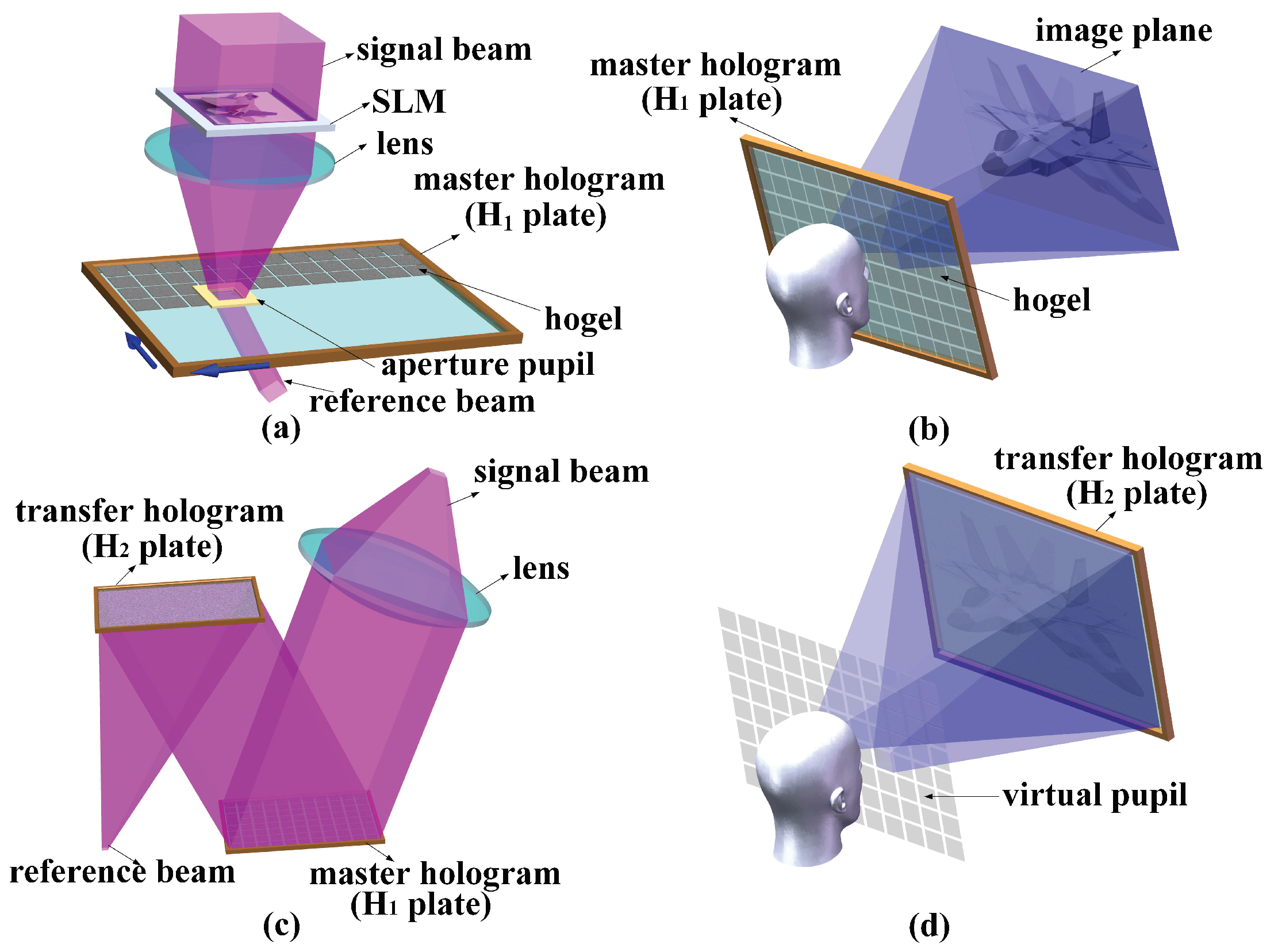
Synthetic holographic stereogram printing was first proposed by DeBitetto [27] and promoted by King et al. [28]. The earliest synthetic holographic stereograms are horizontal-parallax-only (HPO) holographic stereograms. When the viewer is not located at the slit plane of the stereogram, there will be image distortions. The problem will not occur in full parallax holographic stereograms. With the two-step method, we can achieve a real–virtual combined holographic stereogram, i.e., the reconstructed 3D scene is viewed inside or outside of the holographic recording medium. The production and reconstruction of the two-step method is shown in Figure 1 [29]. Full parallax perspective images of the scene are acquired under incoherent illumination, and Fresnel holograms of them are recorded in different hogels (holographic elements) successively (see Figure 1a). When viewing the master hologram, eyes should be close to the positions of aperture pupils (see Figure 1b). To separate the aperture pupil plane and the viewing plane, the master hologram ( plate) should be recopied to the transfer hologram (the plate) with the image hologram photographing method, i.e., there are double exposures in the two-step method (see Figure 1c). When viewing the transfer hologram from different virtual pupil positions, different perspective images can be captured by human eyes, and the stereoscopic vision is formed (see Figure 1d).
Since the 1990s, the media lab of Massachusetts Institute of Technology (MIT), the imaging science and engineering laboratory of Tokyo Institute of Technology, and the General Optics Laboratory (Geola) have been researching the synthetic holographic stereogram printing technique [30]. To simplify the process of the two-step method, they proposed the infinite viewpoint camera method [31,32], the single-step Lippmann method [33,34], and the direct-write digital holography (DWDH) method [3,35,36].
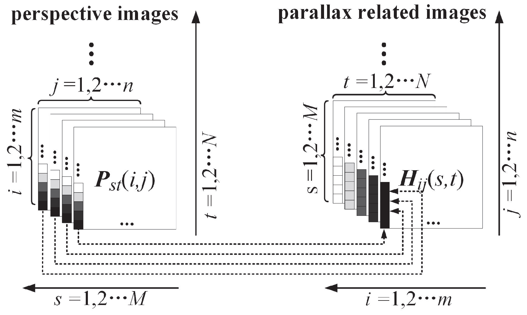
MIT studied the problem of image distortions in HPO holographic stereograms and proposed two predistortion techniques, i.e., the infinite camera predistortion method and the perspective slicing predistortion method. The infinite viewpoint camera method for synthetic holographic stereogram printing was proposed, whose core idea was to transform the perspective images into parallax related images. The perspective images are first captured by an infinite camera, and the light arriving at the hogels can be considered as bundles of parallel light approximately since the distance between the camera and the holographic recording medium is far enough. The transformation is just an operation on a series of arrays as shown in Figure 2 [29]. Suppose there are perspective images, and each image contains pixels. The perspective image matrix is expressed as . All pixels at the same location of each are extracted to form a new matrix , which denotes a parallax-related image. During the holographic printing, a convex lens is used to control the refraction direction of light rays. The resolution of reconstructed images equates to the number of hogels. A double-frustum algorithm for rapidly generating image data for full parallax holographic stereograms was proposed by Halle et al. [37]. There is a special renderer with an orthoscopic camera and a pseudoscopic camera together, and each exposing image is synthesized by using rendering images of these two cameras.
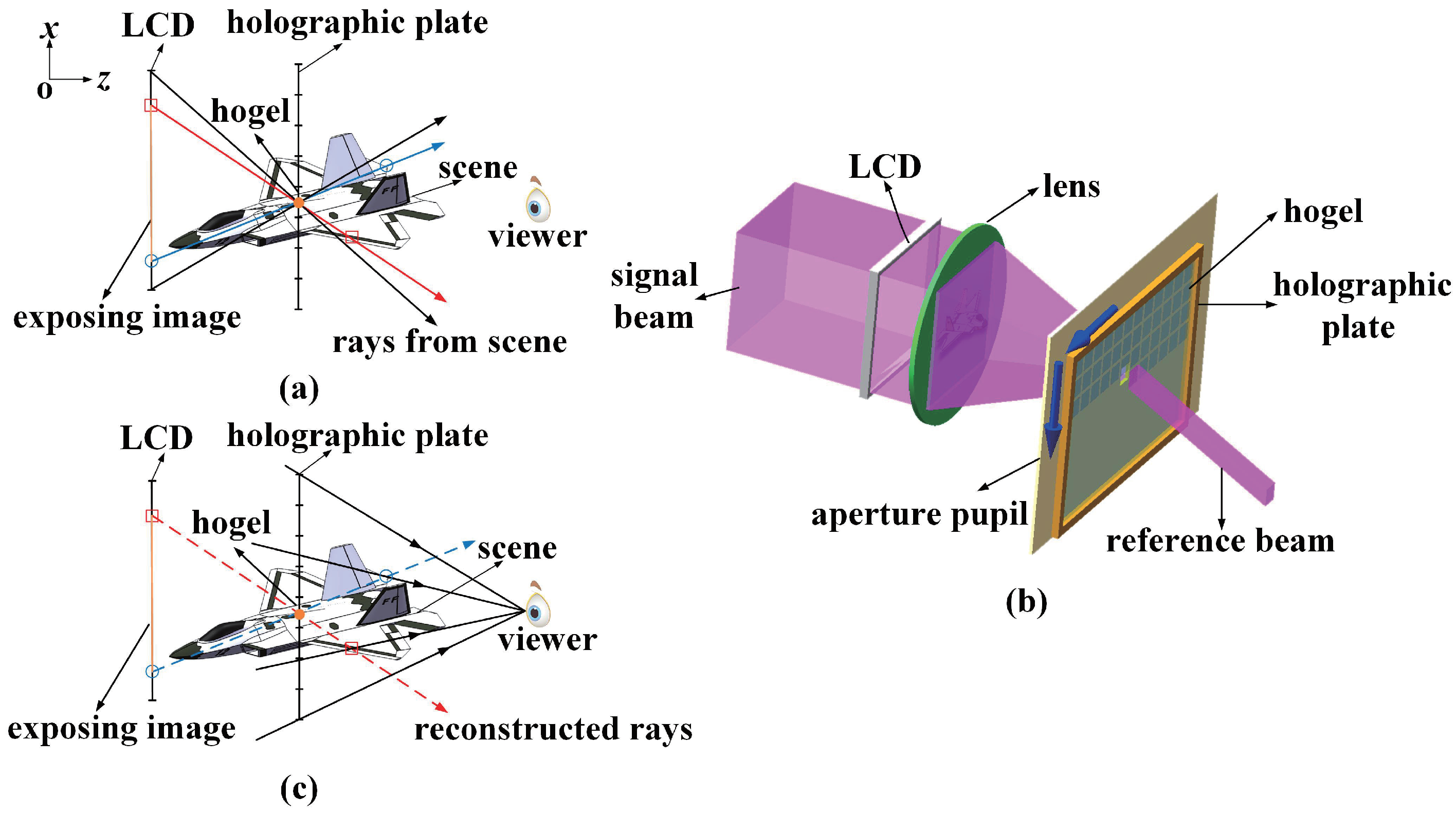
In the single-step Lippmann method, the exposing images for hogels are acquired by the perspective projection, not by camera sampling, and the principle of this method is shown in Figure 3 [29]. Based on the center of each hogel, scene points are projected to the position of liquid crystal display (LCD), respectively (see Figure 3a). According to the viewer’s position, the occlusion relation of scene points in space should be considered and the hidden surfaces should be removed. The calculated images are then displayed on the LCD, converged through the lens, and recorded on the hogels (see Figure 3b). During the reconstruction of the scene, light rays are diffracted from each hogel in the same way as the image calculation; thus, the viewer can perceive the scene (see Figure 3c). The double-frustum algorithm can be also applied to the single-step Lippmann method.
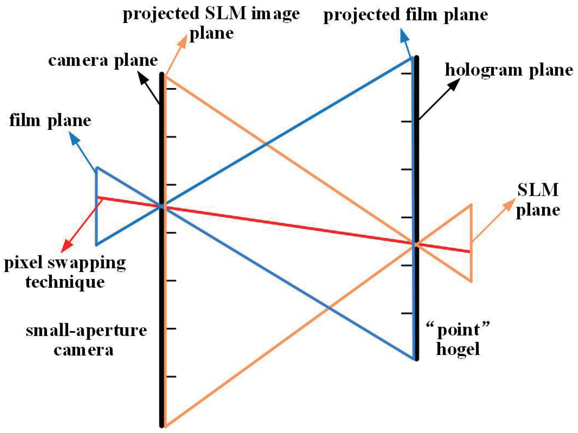
Geola Inc. has realized full parallax holographic stereogram printers with pulse lasers [35], while the commercial products provided by Geola Inc. are only HPO holographic stereograms. The DWDH method was proposed by Bjelkhagen and Brotherton-Ratcliffe. The core idea of the DWDH method is the conversion, i.e., the image transformation from the camera film plane to the SLM plane, which is usually referred as “I-to-S” transforming [38]. The principle of the DWDH method is shown in Figure 4. There are six principal planes, i.e., the hologram plane, the SLM plane, the projected SLM image plane, the camera plane, the film plane, and the projected film plane. There is the assumption of a small-aperture camera and a “point” hogel, and each image of the SLM plane is acquired by the pixel swapping technique from different images of film planes according to the ray-tracing principle. The spatial location relations of these planes are easily established, and there is an exact pixel matching relationship between the SLM plane and film plane.
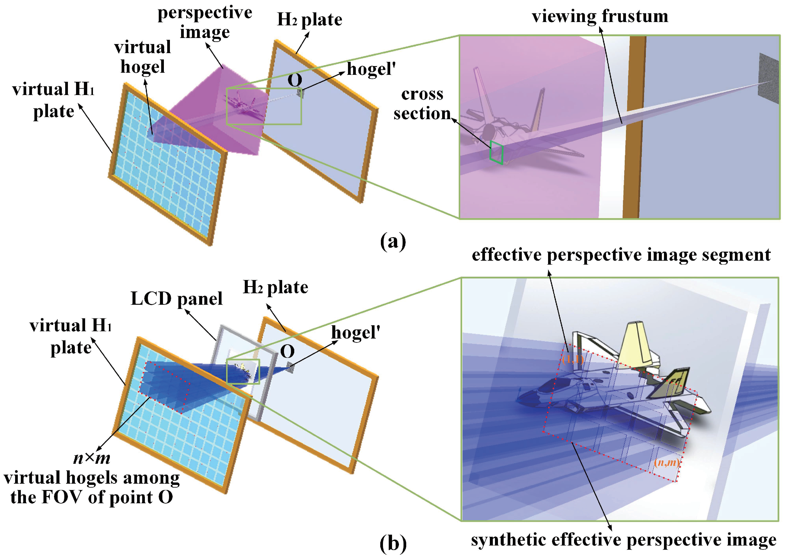
In the two-step method, the process is relatively complex with double exposures, and it is difficult to make a large-size hologram since we can hardly achieve large-format collimating light during the second exposure. There is only single exposure in the infinite viewpoint camera method, in the single-step Lippmann method, or in the DWDH method. Recently, a novel method based on effective perspective image segmentation and mosaicking (EPISM) was proposed by our group [29,38]. The principle of the EPISM method is shown in Figure 5. On the basis of ray-tracing principle and the reversibility of light propagation, the viewing frustum effect of human eyes is analyzed and simulated (see Figure 5a). With the segmentation and mosaicking of effective perspective images, synthetic effective perspective images for single-step exposure can be achieved (see Figure 5b). By using the EPISM holographic stereogram printing method, the image processing is simple and the reconstructed images are of high resolution.
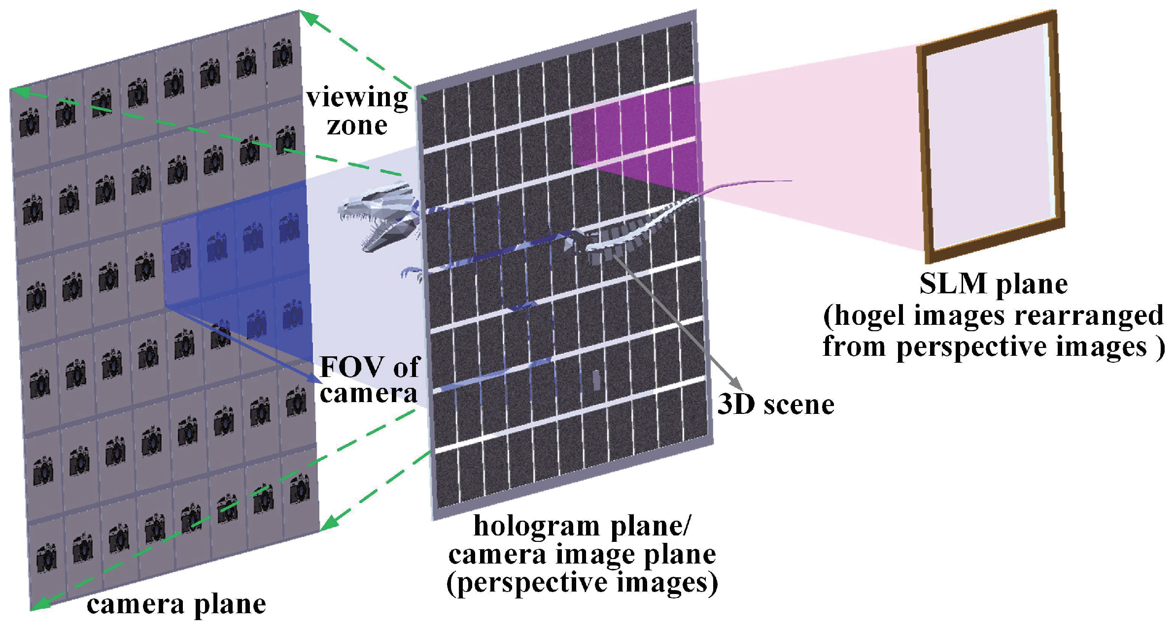
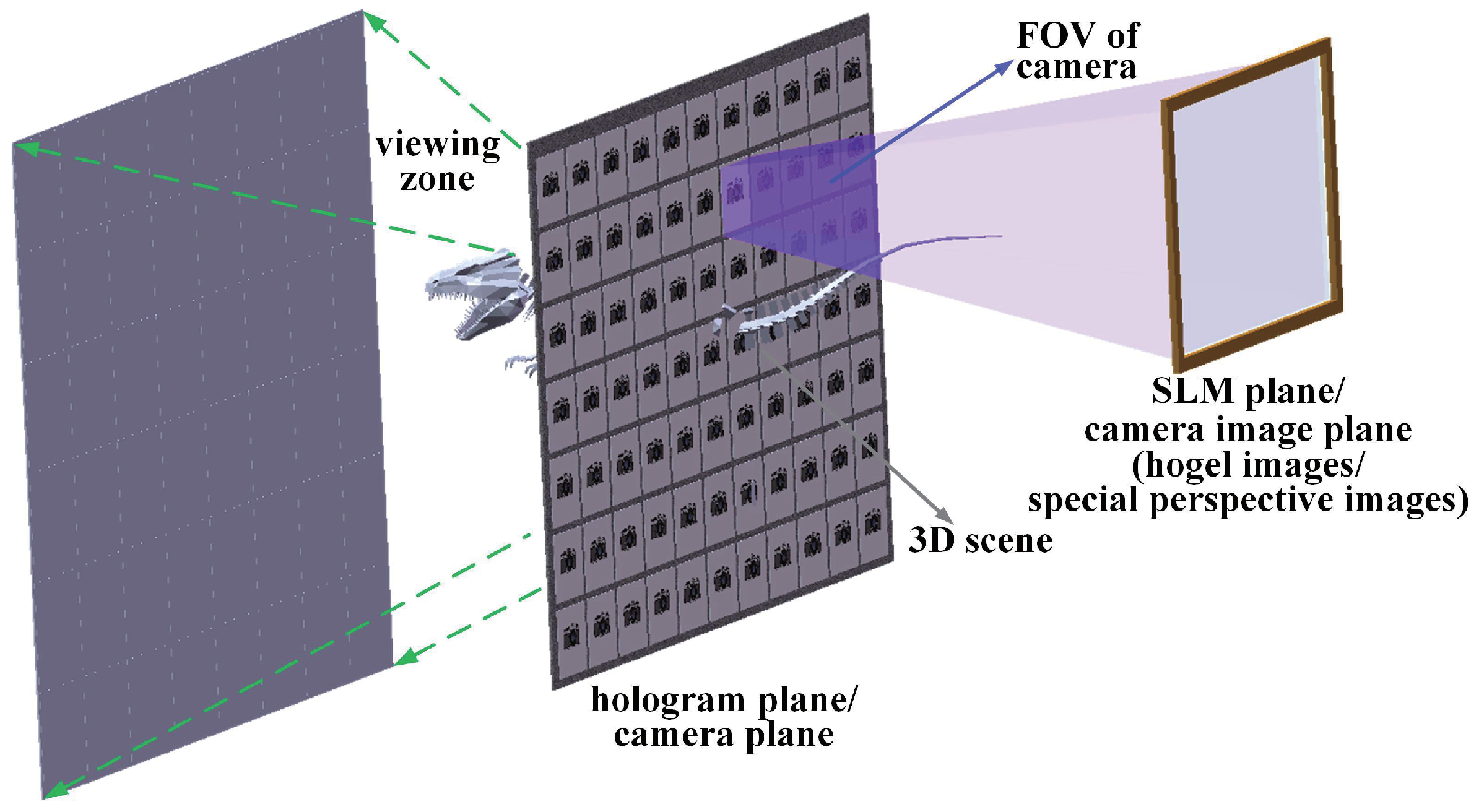
Principles of different synthetic holographic stereogram printing methods have been described. Except for the two-step method, there is only single exposure in the other printing methods. According to different models to generate the hogel images, the methods mentioned above can be classified as two types [39]. In the first type, hogel images are generated by a camera placed on the viewing zone of the holographic stereogram. As shown in Figure 6, the hologram plane coincides with the camera image plane, and the camera is placed on every point of view on the viewing zone. Perspective images of the 3D scene are first captured by the camera, and they are then rearranged to generate hogel images. According to different transformation algorithms, there are examples of the infinite viewpoint camera method and the DWDH method. Although the hologram plane is not matched with the camera image plane in the EPISM method, the EPISM method can be also considered as the first type since the camera is placed on the viewing zone of the holographic stereogram. In the second type, hogel images are generated by a camera placed on the hologram plane. As shown in Figure 7, the camera is placed on every hogel of the holographic stereogram and the SLM plane coincides with the camera image plane. Hogel images are generated directly, and there are examples of the single-step Lippmann method and double-frustum algorithm. The camera’s field of view (FOV) is coincided with the hogel’s FOV, and the hogel image’s resolution coincides with the SLM’s resolution.
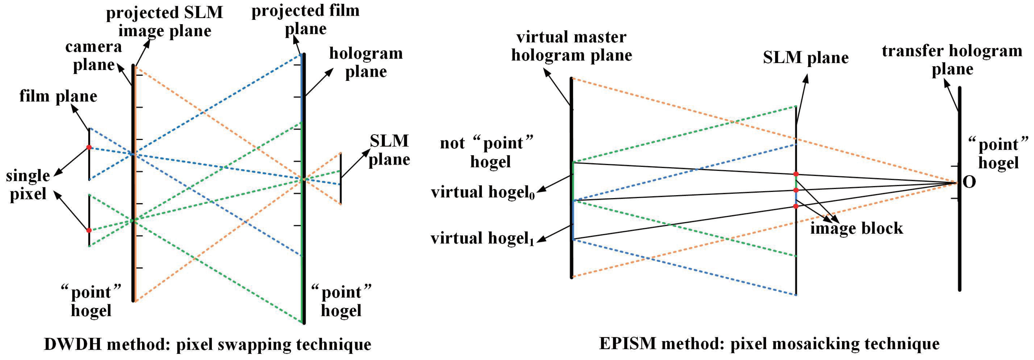
For either the DWDH method or the EPISM method, the core idea is the conversion. However, they are different, as shown in Figure 8. In the DWDH method, there are six principal planes, i.e., the hologram plane, the SLM plane, the projected SLM image plane, the camera plane, the film plane, and the projected film plane. There is the assumption of a small-aperture camera and a “point” hogel, and each image of the SLM plane is acquired by the pixel swapping technique from different images of film planes according to the ray-tracing principle. Consequently, there is an exact pixel matching relationship between the SLM plane and the film plane. Once the parameters of the printing system (such as the distance between the camera plane and the hologram plane as well as the pixel intervals of the film plane and SLM plane) are determined, the relationship between the hogel sizes of the camera plane and the hologram plane are fixed. In our proposed EPISM method, there are only three principal planes, i.e., the virtual master hologram plane, the SLM plane, and the transfer hologram plane, and only the hogels in the transfer hologram are considered as “point” hogels. The virtual master hologram plane and the transfer hologram plane in the EPISM method can be considered equally to the camera plane and the hologram plane in the DWDH method correspondingly. The images for hogels in the transfer hologram are acquired by the pixel mosaicking technique, not the pixel swapping technique. The DWDH method is based on single pixel mapping, whereas the EPISM method is based on the image block operation. The calculation burden in the EPISM method is much less than that of the DWDH method, especially for a full parallax holographic stereogram. Moreover, since it is the pixel mosaicking technique, the hogel sizes in the virtual master hologram and the transfer hologram can be arbitrary, without any limitations.
3. The Research Status of Synthetic Holographic Stereogram Printing
3.1. Holographic Display with a Large Format, a Large Field of View, and No Distortion
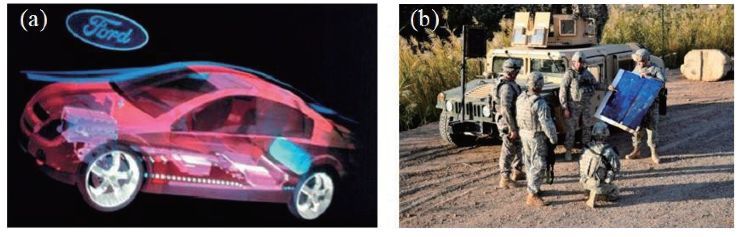
The MIT group studied the principle of synthetic holographic stereogram, which has a large format, a large FOV, and no distortions during image reconstruction. Ultragram was proposed to improve the distortion properties in HPO holographic stereograms [30,31]. A holographic display in the m2 level was achieved with hogels spliced by Benton et al. [40]. Zebra Imaging Inc. was founded by scientists from the media lab of MIT, and has successfully achieved holographic stereogram printing with high quality [41]. Zebra Imaging Inc. has provided tens of thousands of holographic maps for the US army since 2006. Holographic advertisement and holographic map produced by Zebra Imaging Inc. are shown in Figure 9.
From the perspective of diffraction efficiency and the FOV, holographic stereogram printing systems based on a diffuser or a diffraction optical element (DOE) were compared by Zherdev et al. Two embodiments of diffractive lens, i.e., the composite holographic lens (CHL) and the amplitude diffractive lens (ADL), were used to increase the FOV, and the FOV could be up to 120° [42].
Since the objective lens, the telecentric lens, and other optical elements are used in the holographic stereogram printing systems, there will be radial distortions when the images are projected by the SLM [43]. The radial distortions caused by the optical elements during the reconstruction of a full parallax and full color white light viewable holographic stereogram were studied by Park et al., while the peak signal-to-noise ratio (PSNR) and the structural similarity (SSIM) were used as imaging quality metrics [43].
3.2. Printing Efficiency
Printing efficiency is critical in holographic stereogram printing as it is the hogel-by-hogel printing method. The relationship between the total time of holographic printing and the factors such as hogel size, the light sensitivity of recording material, laser output power, exposure time, moving time, and waiting time was studied by Morozov et al. [44]. Spatial splitting technology and time sequential technology were proposed to improve the printing efficiency, and for a hologram with size , the overall printing time 250 min for conventional method reduced to 67 and 32 min, respectively.
A multichannel holographic printing method was proposed by Rong et al. [45]. Each perspective image of the 3D scene was segmented into nonoverlapping subimages, and subimages were rearranged to the encoding images firstly. The SLM was then partitioned into multi-areas that were independent spatially, and each encoding image was loaded to the corresponding channel of the SLM for exposing. With the proposed method, the printing time could be reduced significantly for large-scale holograms.
An array of small lenses and reduction optics were used to realize the parallel exposure by Yamaguchi et al. [46]. Since 12 hogels were simultaneously exposed by each exposure, the printing efficiency could be improved greatly, as the printing speed was about 10 times faster than the conventional method.
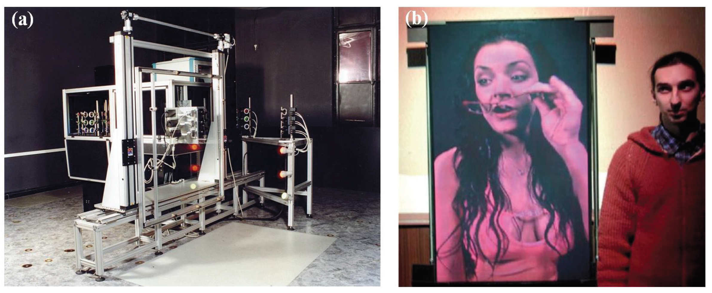
Compared with the continuous wave laser, the pulsed laser is not sensitive to vibrations or tiny temperature fluctuations, so the waiting time could be negligible during the exposure. Many researches and companies have successfully realized the synthetic holographic stereogram printing with pulsed lasers [47,48,49]. Geola Inc. and XYZ Imaging Inc. have cooperated to produce holographic printers, which could print differently sized, high-quality, and colorful holograms automatically. The first RGB pulsed laser holographic printer made by Geola Inc. in 2001 and the printed hologram are shown in Figure 10 [3,47].
3.3. Color Reproduction Characteristic
With the development of the holographic recording medium, color reflection holography has been the focus of research in recent years. The diffraction wavelength selectivity of reflection holography and the colorimetric principle were analyzed, and the expression of reflection hologram colorimetric system was proposed by Wang et al., meanwhile the color reproduction quality of reconstructed images was evaluated [50]. Based on the spectral measurement of reproduced light, a new method of color management for a full-color holographic stereogram printing was proposed by Yamaguchi et al. [51]. The color shifts with the variations of illumination beam angle were also discussed, and it was shown that the specified colors could still be reproduced within a certain range of incident angle variation.
Based on the sensitometric characteristic of the holographic recording medium, multi-exposure [52] or space-division exposure [51] could be used in full-color holographic printing. In the multi-exposure method, the hogels were exposed by a single laser beam which combined the lasers of RGB colors simultaneously, and the recording effect depended on the dynamic range of recording material since there were three different gratings recorded in the region of the hologram [53]. In the space-division exposure method, the hogels were divided into different parts spatially, and each part was exposed with a single-color laser, and the diffracted light intensity would then decrease to one-third of that of monochromatic exposure as the recording density decreased.
A high-density light-ray recording method for a full-color, full-parallax holographic stereogram was proposed by Yamaguchi et al. [54]. RGB lasers were used for the production and reconstruction of colorful holographic stereogram, and the relationship between the hogel size and the reconstruction effects, such as the angular resolution and the visibility of the hogel’s array structure, was discussed. Experiment results showed that the angular resolution of reproduced light rays was 1.08° when the hogel size was 50 × 50 µm, which could satisfy the demand of the human visual system.
3.4. Imaging Quality
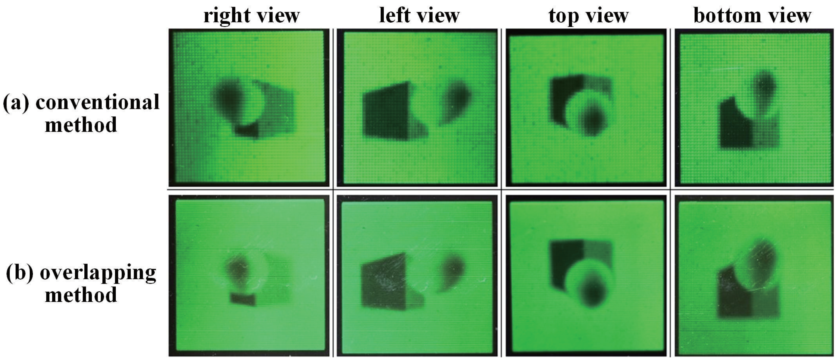
The relationship between the hogel size and the lateral resolution of the stereogram was analyzed by Lucente [55]. A hogel overlapping method for enhancing the lateral resolution of holographic stereogram was proposed by Hong et al. [56]. The shifting distance of hogel was smaller than the hogel size, and the maximum number of recordable overlapped hogels depended on the dynamic range of the holographic recording medium. Perspective images captured from different viewing points for the conventional and overlapping methods are shown in Figure 11. However, with such hard pupils overlapped method, the reconstructed images were blurred because of spectral aliasing.
A band-limited diffuser was localized before the holographic recording medium to produce a high-resolution holographic stereogram by Yamaguchi et al., but some additional noises were introduced [57].
3.5. Diffraction Efficiency
Diffraction efficiency of the hologram is related to various factors, such as the properties of the recording medium, the light intensity ratio between the signal beam and the reference beam, the polarization properties of the beams, and the follow-up processing. Diffraction efficiency is highest when the light intensity ratio between the signal beam and the reference beam is about 1. A pseudorandom band-limited diffuser was used to modulate the signal beam and broaden the frequency spectrum of the Fourier-plane of the lens by Klug et al., and this resulted in an improvement of diffraction efficiency [58].
Additionally, in the optical hologram, from the perspective of the recording medium’s properties, some scholars have added nanoparticles to the recording materials to improve the diffraction efficiency, and the research results could also be applied to the holographic printing. For instance, 13 nm silica nanoparticles were added to the methacrylate photopolymers by Suzuki et al., and a noticeable reduction of scattering loss and a high-contrast refractive-index change were achieved [59]. A gold-nanoparticle-doped photopolymer was used to suppress side lobes of angle selectivity of volume holographic gratings by Cao et al., achieving a higher diffraction efficiency [60,61].
3.6. The Development of a Holographic Recording Medium
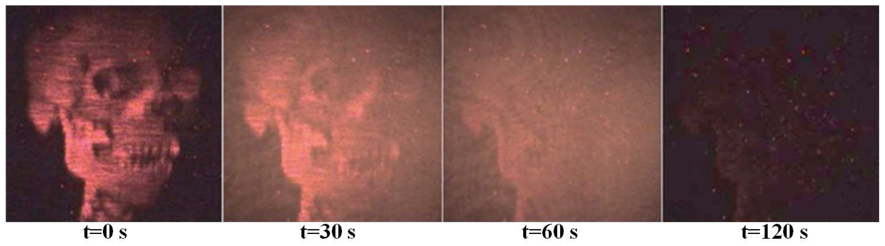
Three main types of holographic recording medium are silver-halide materials, dichromate gelatin materials, and photopolymer materials [3]. With such conventional materials, the holograms cannot be modified once the information is recorded into the materials, which means the lack of image-updating capability, leading to restricted use and high cost. Consequently, many scholars are committed to the study of updatable holographic recording medium. A holographic stereogram was recorded into a photorefractive polymer material achieved by Peyghambarian et al., resulting in a dynamically updatable holographic display, which could refresh images every 2 s [62,63]. Images from the updatable holographic 3D display is shown in Figure 12. Poly-doped organic compound was used in a holographic stereographic technique by Tsutsumi et al., resulting in an updatable holographic 3D display with fast response time and high diffraction efficiency [64,65]. A permanent holographic recording photosensitive material with high diffraction efficiency of about 90% was investigated by Gao et al. [66,67].
3.7. Noises Reduction
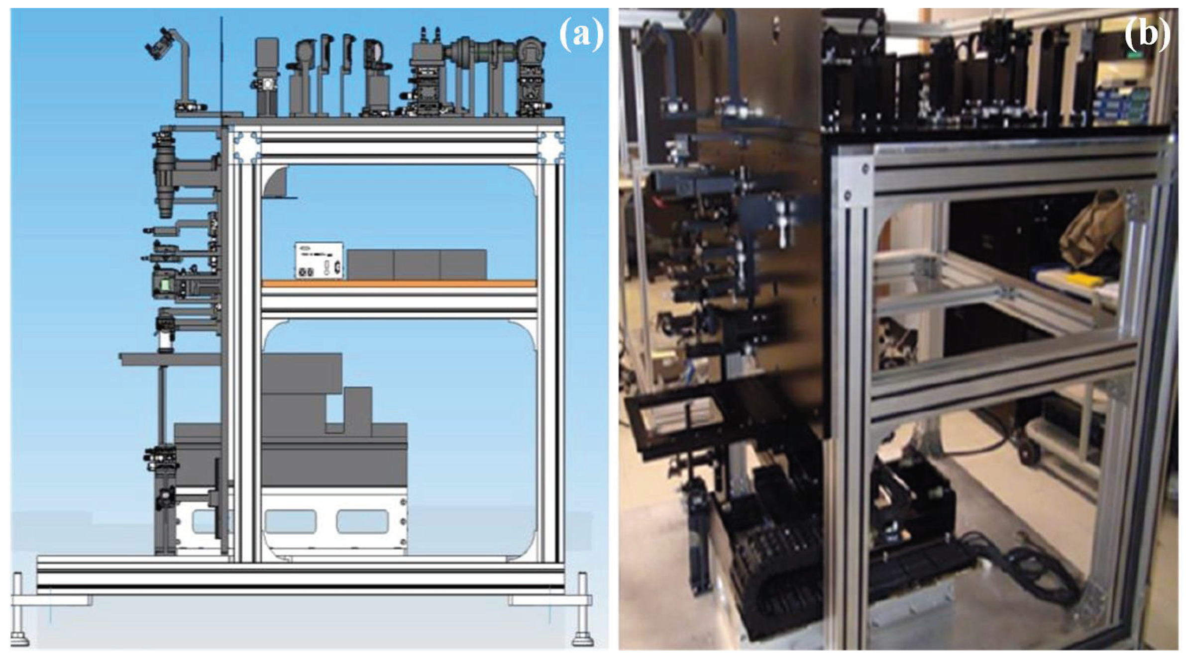
In synthetic holographic stereogram printing, since it is usually set up on an anti-vibration system with an optical table, the main source of the noises comes from the movement of the motorized X-Y stage with the holographic recording medium hogel by hogel. In order to enhance the robustness of the printing system against the ambient noises, an anti-vibration algorithm was designed and applied by Lee et al., reducing the vibration significantly [68]. The schematic and prototype of the holographic stereogram printer is shown in Figure 13.
The problem of speckle noises in synthetic holographic stereogram printing was also studied by Yamaguchi et al. [57]. A diffuser was used in the printing system to equalize the intensity distribution of the signal beam inside the hogel, but it would generate speckles. A moving diffuser was used to suppress the granularity noises and a multiple exposure method was used to suppress the high-frequency noises.
3.8. Frequency Response Analysis of the Holographic Stereogram
Holographic stereogram is an optical system, especially a diffraction limited system. It is difficult to understand the working mechanism of the system comprehensively if just from the perspective of geometrical optics. Considering from the angular spectrum, some scholars establish the angular regulation model, analyze the regulation mechanism, and discuss the frequency response of the holographic stereogram [69].
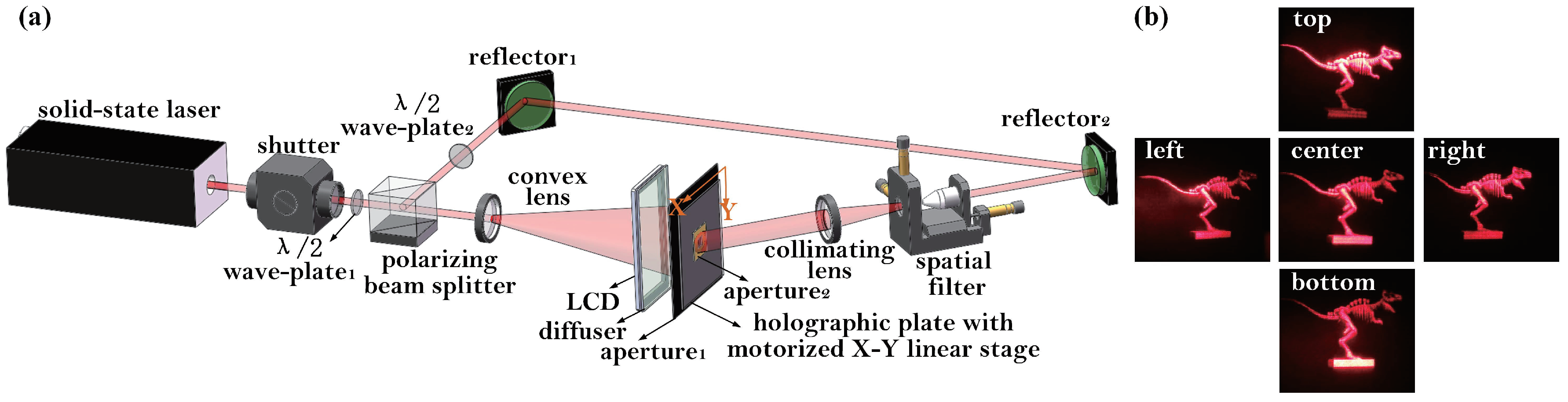
The modulation transfer function (MTF) of HPO image-plane holographic stereograms was constructed by St Hilaire et al., and the optimum sampling of the slit plane with fixed depth object points was also discussed [70]. The optical transfer function (OTF) of 3D display systems was investigated by Helseth et al., and the influence of the Stiles–Crawford effect of human eyes was also considered [71]. In our previous study, the wavefront reconstructed errors in the holographic stereogram were expressed as defocusing aberrations, and the frequency responses of the full-parallax holographic stereogram were studied when the Rectangle, the shaped Gaussian, and the shaped Blackman window functions were used as the exit pupil functions, respectively. The design criterion of the exit pupil function was then discussed [72]. Moreover, exit modeling and OTF analysis of the EPSIM-based holographic stereogram were carried out [38]. Characteristics of the OTF with respect to the exit pupil size and the aberration were investigated in detail. Hogel sizes, i.e., the sampling interval of original perspective images and the printing interval of synthetic effective perspective images, were optimized for the reconstruction. Optical setup of the holographic stereogram printing system and images of optical reconstruction from different perspectives are shown in Figure 14.
4. Conclusions
Holographic printing techniques can be used for a realistic 3D display, and synthetic holographic stereogram printing is the only holographic printing technique in application currently. In this paper, the development and research status of the synthetic holographic stereogram printing technique is introduced in detail. We predict that the synthetic holographic stereogram printing technique will rapidly develop and that holographic stereogram printers will enter our daily lives for personal use in the future.
Author Contributions
J.S. structured and wrote the paper; X.Y. selected topic and supervised the progress of the whole work; Y.H. guided other authors to complete the paper; X.J. and Y.C. supplied the materials to the paper; T.Z. helped to proofread the manuscript.
Acknowledgments
The authors are grateful to the National Key Research and Development Program of China (Grant No.2017YFB1104500), the National Natural Science Foundation of China (Grant No.61775240), and the Foundation for the Author of National Excellent Doctoral Dissertation of the People’s Republic of China (FANEDD) (Grant No.201432).
Conflicts of Interest
The authors declare no conflict of interest.
References
- Gabor, D. A new microscopic principle. Nature 1948, 161, 777–778. [Google Scholar] [CrossRef] [PubMed]
- Lucente, M. The first 20 years of holographic video—And the next 20. In Proceedings of the SMPTE 2nd Annual International Conference on Stereoscopic 3D for Media and Entertainment, New York, NY, USA, 21–23 June 2011. [Google Scholar]
- Bjelkhagen, H.I.; Brotherton-Ratcliffe, D. Ultrarealistic imaging: The future of display holography. Opt. Eng. 2014, 53, 112310. [Google Scholar] [CrossRef]
- Yamaguchi, M. Full-parallax holographic light-field 3-D displays and interactive 3-D touch. Proc. IEEE 2017, 105, 947–959. [Google Scholar] [CrossRef]
- Park, J.S.; Stoykova, E.; Kang, H.J. White light viewable silver-halide holograms in design applications. Bulg. Chem. Commun. 2016, 48, 37–40. [Google Scholar]
- Zheng, H.; Sun, G.; Yu, Y. A review of holographic printing technologies. Laser Optoelectron. Prog. 2012, 49, 110002. (In Chinese) [Google Scholar] [CrossRef]
- Yamaguchi, M. Light-field and holographic three-dimensional displays [Invited]. J. Opt. Soc. Am. A 2016, 33, 2348–2364. [Google Scholar] [CrossRef] [PubMed]
- Kang, H.; Stoykova, E.; Berberova, N.; Park, J.; Nazarova, D.; Park, J.S.; Kim, Y.; Hong, S.; Ivanov, B.; Malinowski, N. Three-dimensional imaging of cultural heritage artifacts with holographic printers. In Proceedings of the SPIE 19th International Conference and School on Quantum Electronics: Laser Physics and Applications, Sozopol, Bulgaria, 26–30 September 2016; Volume 10226, p. 102261I. [Google Scholar]
- Yoshikawa, H.; Yamaguchi, T. Review of holographic printers for computer-generated holograms. IEEE Trans. Ind. Inform. 2016, 12, 1584–1589. [Google Scholar] [CrossRef]
- Jolly, S.; Smalley, D.E.; Barabas, J.; Bove, V.M. Direct fringe writing architecture for photorefractive polymer-based holographic displays: Analysis and implementation. Opt. Eng. 2013, 52, 055801. [Google Scholar] [CrossRef]
- Yoshikawa, H. Research activities on digital holographic displays in Japan. In Proceedings of the SPIE Three-Dimensional Imaging, Visualization, and Display 2011, Orlando, FL, USA, 25–29 April 2011; Volume 8043, p. 804305. [Google Scholar]
- Li, Y.; Wang, H.; Ma, L.; Shi, Y. Three-dimensional imaging and display of real-existing scene using fringe. In Proceedings of the SPIE International Conference on Optics in Precision Engineering and Nanotechnology (icOPEN2013), Singapore, 9–11 April 2013; Volume 8769, p. 87691I. [Google Scholar]
- Yoshikawa, H.; Yamaguchi, T. Computer-generated holograms for 3D display (Invited Paper). Chin. Opt. Lett. 2009, 7, 1079–1082. [Google Scholar]
- Su, J.; Yan, X.; Huang, Y.; Chen, Y.; Jiang, X. Resolution matching in laser direct printing of a computer-generated hologram. J. Opt. Soc. Am. B 2017, 34, B1–B8. [Google Scholar] [CrossRef]
- Yoshikawa, H.; Takei, K. Development of a compact direct fringe printer for computer-generated holograms. In Proceedings of the SPIE Practical Holography XVIII: Materials and Applications, San Jose, CA, USA, 18–22 January 2004; Volume 5290, pp. 114–121. [Google Scholar]
- Yamaguchi, T.; Yoshikawa, H. Computer-generated image hologram. Chin. Opt. Lett. 2011, 9, 120006. [Google Scholar] [CrossRef]
- Sohn, I.B.; Choi, H.K.; Yoo, D.; Noh, Y.C.; Noh, J.; Ahsan, M.S. Three-dimensional hologram printing by single beam femtosecond laser direct writing. Appl. Surf. Sci. 2018, 427, 396–400. [Google Scholar] [CrossRef]
- Kang, H.; Stoykova, E.; Yoshikawa, H.; Hong, S.; Kim, Y. Comparison of System Properties for Wave-Front Holographic Printers; Osten, W., Ed.; Springer: Berlin/Heidelberg, Germany, 2014; pp. 851–854. ISBN 978-3-642-36359-7. [Google Scholar]
- Oi, R.; Chou, P.-Y.; Jackin, B.J.; Wakunami, K.; Ichihashi, Y.; Okui, M.; Huang, Y.-P.; Yamamoto, K. Three-dimensional reflection screens fabricated by holographic wavefront printer. Opt. Eng. 2018, 57, 061605. [Google Scholar]
- Yamaguchi, T.; Miyamoto, O.; Yoshikawa, H. Volume hologram printer to record the wavefront of three-dimensional objects. Opt. Eng. 2012, 51, 075802. [Google Scholar] [CrossRef]
- Kim, Y.; Stoykova, E.; Kang, H.; Hong, S.; Park, J.; Park, J.; Hong, J. Seamless full color holographic printing method based on spatial partitioning of SLM. Opt. Express 2015, 23, 172–182. [Google Scholar] [CrossRef] [PubMed]
- Kang, H.; Stoykova, E.; Kim, Y.; Hong, S.; Park, J.; Hong, J. Color holographic wavefront printing technique for realistic representation. IEEE Trans. Ind. Inform. 2017, 12, 1590–1598. [Google Scholar] [CrossRef]
- Kang, H.; Stoykova, E.; Kim, Y.; Hong, S.; Park, J.; Hong, J. Color wavefront printer with mosaic delivery of primary colors. Opt. Commun. 2015, 350, 47–55. [Google Scholar] [CrossRef]
- Cao, L.; Wang, Z.; Zhang, H.; Jin, G.; Gu, C. Volume holographic printing using unconventional angular multiplexing for three-dimensional display. Appl. Opt. 2016, 55, 6046–6051. [Google Scholar] [CrossRef] [PubMed]
- Wakunami, K.; Oi, R.; Senoh, T.; Ichihashi, Y.; Yamamoto, K. Wavefront printing technique with overlapping approach toward high definition holographic image reconstruction. In Proceedings of the SPIE Three-Dimensional Imaging, Visualization, and Display 2016, Baltimore, MD, USA, 17–21 April 2016; Volume 9867, p. 98670J. [Google Scholar]
- Ichihashi, Y.; Yamamoto, K.; Wakunami, K.; Oi, R.; Okui, M.; Senoh, T. An analysis of printing conditions for wavefront overlapping printing. In Proceedings of the SPIE Practical Holography XXXI: Materials and Applications, San Francisco, CA, USA, 28 January–2 February 2017; Volume 10127, p. 101270L. [Google Scholar]
- DeBitetto, D.J. Holographic panoramic stereograms synthesized from white light recordings. Appl. Opt. 1969, 8, 1740–1741. [Google Scholar] [CrossRef] [PubMed]
- King, M.C.; Noll, A.M.; Berry, D.H. A new approach to computer-generated holography. Appl. Opt. 1970, 9, 471–476. [Google Scholar] [CrossRef] [PubMed]
- Su, J.; Yuan, Q.; Huang, Y.; Jiang, X.; Yan, X. Method of single-step full parallax synthetic holographic stereogram printing based on effective perspective images’ segmentation and mosaicking. Opt. Express 2017, 25, 23523–23544. [Google Scholar] [CrossRef] [PubMed]
- Kang, H.; Stoykova, E.; Park, J.; Hong, S.; Kim, Y. Holographic Printing of White-Light Viewable Holograms and Stereograms; Mihaylova, E., Ed.; InTech: London, UK, 2013; pp. 171–201. ISBN 978-953-51-1117-7. [Google Scholar]
- Halle, M.W.; Benton, S.A.; Klug, M.A.; Underkoffler, J.S. Ultrgram: A generalized holographic stereogram. In Proceedings of the SPIE Practical Holography V, San Jose, CA, USA, 1–7 February 1991; Volume 1461, pp. 142–155. [Google Scholar]
- Halle, M.W. The Generalized Holographic Stereogram. Master’s Thesis, Massachusetts Institute of Technology, Cambridge, MA, USA, 1991. [Google Scholar]
- Yamaguchi, M.; Ohyama, N.; Honda, T. Holographic three-dimensional printer: New method. Appl. Opt. 1992, 31, 217–222. [Google Scholar] [CrossRef] [PubMed]
- Yamaguchi, M.; Endoh, H.; Honda, T.; Ohyama, N. High-quality recording of a full-parallax holographic sterogram with a digital diffuser. Opt. Lett. 1994, 19, 135–137. [Google Scholar] [CrossRef] [PubMed]
- Bjelkhagen, H.I.; Brotherton-Ratcliffe, D. Ultra-Realistic Imaging: Advanced Techniques in Analogue and Digital Colour Holography; CRC Press: Boca Raton, FL, USA, 2013; ISBN 978-1-4398-2800-7. [Google Scholar]
- Brotherton-Ratcliffe, D.; Rodin, A. Holographic Printer. U.S. Patent 7,161,722, 9 January 2007. [Google Scholar]
- Halle, M.W.; Kropp, A.B. Fast computer graphics rendering for full parallax spatial displays. In Proceedings of the SPIE Practical Holography XI and Holographic Materials III, San Jose, CA, USA, 8–14 February 1997; Volume 3011, pp. 105–112. [Google Scholar]
- Su, J.; Yan, X.; Jiang, X.; Huang, Y.; Chen, Y.; Zhang, T. Characteristic and optimization of the effective perspective images’ segmentation and mosaicking (EPISM) based holographic stereogram: An optical transfer function approachg. Sci. Rep. 2018, 8, 4488. [Google Scholar] [CrossRef] [PubMed]
- Sánchez, A.M.; Prieto, D.V. Design, development and implementation of a low-cost full-parallax holoprinter. In Proceedings of the SPIE Practical Holography XXXII: Displays, Materials, and Applications, San Francisco, CA, USA, 27 January–1 February 2018; Volume 10558, p. 105580H. [Google Scholar]
- Benton, S.A.; Bove, V.M. Holographic Imaging; John Wiley & Sons: Hoboken, NJ, USA, 2008; ISBN 978-0-470-06806-9. [Google Scholar]
- Newswanger, C.; Klug, M. Holograms for the masses. In Proceedings of the 9th International Symposium on Display Holography (ISDH), Cambridge, MA, USA, 25–29 June 2012; Volume 415, p. 012082. [Google Scholar]
- Zherdev, A.Y.; Odinokov, S.B.; Lushnikov, D.S.; Shishova, M.V.; Gurylev, O.A.; Kaytukov, C.B. High-aperture diffractive lens for holographic printer. In Proceedings of the SPIE, Holography, Diffractive Optics, and Applications VII, Beijing, China, 12–14 October 2016; Volume 10022, p. 100220I. [Google Scholar]
- Park, J.; Kang, H.; Stoykova, E.; Kim, Y.; Hong, S.; Choi, Y.; Kwon, S.; Lee, S. Numerical reconstruction of a full parallax holographic stereogram with radial distortion. Opt. Express 2014, 22, 20776–20788. [Google Scholar] [CrossRef] [PubMed]
- Morozov, A.V.; Putilin, A.N.; Kopenkin, S.S.; Borodin, Y.P.; Druzhin, V.V.; Dubynin, S.E.; Dubinin, G.B. 3D holographic printer: Fast printing approach. Opt. Express 2014, 22, 2193–2206. [Google Scholar] [CrossRef] [PubMed]
- Rong, X.; Yu, X.; Guan, C. Multichannel holographic recording method for three-dimensional displays. Appl. Opt. 2011, 50, B77–B80. [Google Scholar] [CrossRef] [PubMed]
- Yamaguchi, M.; Endoh, H.; Koyama, T.; Ohyama, N. High-speed recording of full-parallax holographic stereograms by a parallel exposure system. Opt. Eng. 1996, 35, 1556–1559. [Google Scholar] [CrossRef]
- Brotherton-Ratcliffe, D.; Zacharovas, S.J.; Bakanas, R.J.; Pileckas, J.; Nikolskij, A.; Kuchin, J. Digital holographic printing using pulsed RGB lasers. Opt. Eng. 2011, 50, 091307. [Google Scholar]
- Bakanas, R.; Jankauskaitė, V.; Bulanovs, A.; Zacharovas, S.; Vilkauskas, A. Comparison of diffraction patterns exposed by pulsed and CW lasers on positive-tone photoresist. Appl. Opt. 2017, 56, 2241–2249. [Google Scholar] [CrossRef] [PubMed]
- Brotherton-Ratcliffe, D.; Vergnes, F.M.R.; Rodin, A.; Grichine, M. Holographic Printer. U.S. Patent 7,800,803, 21 September 2010. [Google Scholar]
- Wu, Q.; Wang, H.; Shi, Y.; Li, Y. Color reproduction quantitative analysis of color reflection holography. Chin. J. Lasers 2016, 43, 213–221. (In Chinese) [Google Scholar]
- Yang, F.; Murakami, Y.; Yamaguchi, M. Digital color management in full-color holographic three-dimensional printer. Appl. Opt. 2012, 51, 4343–4352. [Google Scholar] [CrossRef] [PubMed]
- Takano, M.; Shigeta, H.; Nishihara, T.; Yamaguchi, M.; Takahashi, S.; Ohyama, N.; Kobayashi, A.; Iwata, F. Full-color holographic 3D printer. In Proceedings of the SPIE Practical Holography XVII and Holographic Materials IX, Santa Clara, CA, USA, 20–24 January 2003; Volume 5005, pp. 126–136. [Google Scholar]
- Bjelkhagen, H.I.; Mirlis, E. Color holography to produce highly realistic three-dimensional images. Appl. Opt. 2008, 47, 123–133. [Google Scholar] [CrossRef]
- Maruyama, S.; Ono, Y.; Yamaguchi, M. High-density recording of full-color full-parallax holographic stereogram. In Proceedings of the SPIE, Practical Holography XXII: Materials and Applications, San Jose, CA, USA, 19–24 January 2008; Volume 6912, p. 69120N. [Google Scholar]
- Lucente, M. Diffraction-Specific Fringe Computation for Electro-Holography. Ph.D. Thesis, Massachusetts Institute of Technology, Cambridge, MA, USA, 1994. [Google Scholar]
- Hong, K.; Park, S.-G.; Yeom, J.; Kim, J.; Chen, N.; Pyun, K.; Choi, C.; Kim, S.; An, J.; Lee, H.-S.; et al. Resolution enhancement of holographic printer using a hogel overlapping method. Opt. Express 2013, 21, 14047–14055. [Google Scholar] [CrossRef] [PubMed]
- Utsugi, T.; Yamaguchi, M. Reduction of the recorded speckle noise in holographic 3D printer. Opt. Express 2013, 21, 662–674. [Google Scholar] [CrossRef] [PubMed]
- Klug, M.A.; Halle, M.W.; Lucente, M.; Plesniak, W.J. A compact prototype one-step Ultragram printer. In Proceedings of the SPIE Practical Holography VII: Imaging and Materials, San Jose, CA, USA, 31 January–5 February 1993; Volume 1914, pp. 15–24. [Google Scholar]
- Suzuki, N.; Tomita, Y. Silica-nanoparticle-dispersed methacrylate photopolymers with net diffraction efficiency near 100%. Appl. Opt. 2004, 43, 2125–2129. [Google Scholar] [CrossRef] [PubMed]
- Li, C.; Cao, L.; Wang, Z.; Jin, G. Hybrid polarization-angle multiplexing for volume holography in gold nanoparticle-doped photopolymer. Opt. Lett. 2014, 39, 6891–6894. [Google Scholar] [CrossRef] [PubMed]
- Li, C.; Cao, L.; Li, J.; He, Q.; Jin, G.; Zhang, S.; Zhang, F. Improvement of volume holographic performance by plasmon-induced holographic absorption grating. Appl. Phys. Lett. 2013, 102, 061108. [Google Scholar] [CrossRef]
- Tay, S.; Blanche, P.-A.; Voorakaranam, R.; Tunç, A.V.; Lin, W.; Rokutanda, S.; Gu, T.; Flores, D.; Wang, P.; Li, G.; et al. An updatable holographic three-dimensional display. Nature 2008, 451, 694–698. [Google Scholar] [CrossRef] [PubMed]
- Blanche, P.-A.; Bablumian, A.; Voorakaranam, R.; Christenson, C.; Lin, W.; Gu, T.; Flores, D.; Wang, P.; Hsieh, W.-Y.; Kathaperumal, M.; et al. Holographic three-dimensional telepresence using large-area photorefractive polymer. Nature 2010, 468, 80–83. [Google Scholar] [CrossRef] [PubMed]
- Tsutsumi, N.; Kinashi, K.; Tada, K.; Fukuzawa, K.; Kawabe, Y. Fully updatable three-dimensional holographic stereogram display device based on organic monolithic compound. Opt. Express 2013, 21, 19880–19884. [Google Scholar] [CrossRef] [PubMed]
- Tsutsumi, N.; Kinashi, K.; Sakai, W.; Nishide, J.; Kawabe, Y.; Sasabe, H. Real-time three-dimensional holographic display using a monolithic organic compound dispersed film. Opt. Mater. Express 2012, 2, 1003–1010. [Google Scholar] [CrossRef]
- Gao, H.; Liu, P.; Liu, J.; Zheng, Z.; Yao, Q.; Zhou, W.; Xu, F.; Yu, Y.; Zheng, H. Study on permanent holographic recording in trimethylol propane triacrylate-based photopolymer films with high diffraction efficiency. J. Opt. Soc. Am. B 2017, 34, B22–B27. [Google Scholar] [CrossRef]
- Gao, H.; Liu, P.; Zeng, C.; Yao, Q.; Zheng, Z.; Liu, J.; Zheng, H.; Yu, Y.; Zeng, Z.; Sun, T. Holographic storage of three-dimensional image and data using photopolymer and polymer dispersed liquid crystal films. Chin. Phys. B 2016, 25, 094205. [Google Scholar] [CrossRef]
- Lee, B.; Kim, J.-H.; Moon, K.; Kim, I.-J.; Kim, J. Holographic stereogram printing under the non-vibration environment. In Proceedings of the SPIE Three-Dimensional Imaging, Visualization, and Display 2014, Baltimore, MD, USA, 5–9 May 2014; Volume 9117, p. 911704. [Google Scholar]
- Plesniak, W.; Halle, M.; Bove, V.M.; Barabas, J.; Pappu, R. Reconfigurable image projection holograms. Opt. Eng. 2006, 45, 2365–2372. [Google Scholar] [CrossRef]
- St Hilaire, P. Modulation transfer function and optimum sampling of holographic stereograms. Appl. Opt. 1994, 33, 768–774. [Google Scholar] [CrossRef] [PubMed]
- Helseth, L.E. Optical transfer function of three-dimensional display systems. J. Opt. Soc. Am. A 2006, 23, 816–820. [Google Scholar] [CrossRef]
- Jiang, X.; Pei, C.; Liu, J.; Zhao, K.; Yan, X. Optimization of exit pupil function: Improvement on the OTF of full parallax holographic stereograms. J. Opt. 2013, 15, 125402. [Google Scholar] [CrossRef]
Figure 1.
Production and reconstruction of the two-step method. (a) The production of the master hologram. (b) The reconstruction of the master hologram. (c) The reproduction of the master hologram to the transfer hologram. (d) The reconstruction of the transfer hologram. (Reprinted with permission from ref [29], [OSA]).

Figure 2.
Transformation principle of perspective images in the infinite viewpoint camera method. (Reprinted with permission from ref [29], [OSA]).
Figure 2.
Transformation principle of perspective images in the infinite viewpoint camera method. (Reprinted with permission from ref [29], [OSA]).

Figure 3.
Principle of the single-step Lippmann method. (a) Calculation of an exposing image. (b) Optical setup of the method. (c) Reconstruction geometry for the holographic stereogram. (Reprinted with permission from ref [29], [OSA]).
Figure 3.
Principle of the single-step Lippmann method. (a) Calculation of an exposing image. (b) Optical setup of the method. (c) Reconstruction geometry for the holographic stereogram. (Reprinted with permission from ref [29], [OSA]).

Figure 4.
Principle of the direct-write digital holography (DWDH) method.

Figure 5.
Principle of the effective perspective image segmentation and mosaicking (EPISM) method. (a) The extraction of effective perspective image segment corresponding to a single virtual hogel. (b) The synthetic effective perspective image mosaicked by effective images segments of multiple virtual hogels. (Reprinted with permission from ref [29], [OSA]).

Figure 6.
Hogel images are generated by a camera placed on the viewing zone of the holographic stereogram.
Figure 6.
Hogel images are generated by a camera placed on the viewing zone of the holographic stereogram.

Figure 7.
Hogel images are generated by a camera placed on the hologram plane.

Figure 8.
Differences between the DWDH method and the EPISM method.

Figure 9.
Holographic advertisement (a) and holographic map (b) produced by Zebra Imaging Inc.

Figure 10.
The first RGB pulsed laser holographic printer made by Geola in 2001 (a) and the printed hologram (b). (Reprinted with permission from ref [47], [SPIE]).
Figure 10.
The first RGB pulsed laser holographic printer made by Geola in 2001 (a) and the printed hologram (b). (Reprinted with permission from ref [47], [SPIE]).

Figure 11.
Perspective images captured from different viewing points by Hong’s group: (a) conventional method and (b) overlapping method. (Reprinted with permission from ref [56], [OSA]).
Figure 11.
Perspective images captured from different viewing points by Hong’s group: (a) conventional method and (b) overlapping method. (Reprinted with permission from ref [56], [OSA]).

Figure 12.
Images from the updatable holographic 3D display achieved by Peyghambarian’s group. (Reprinted with permission from ref [62], [Springer Nature]).
Figure 12.
Images from the updatable holographic 3D display achieved by Peyghambarian’s group. (Reprinted with permission from ref [62], [Springer Nature]).

Figure 13.
Schematic and prototype of the holographic stereogram printer produced by Lee’s group. (Reprinted with permission from ref [68], [SPIE]).
Figure 13.
Schematic and prototype of the holographic stereogram printer produced by Lee’s group. (Reprinted with permission from ref [68], [SPIE]).

Figure 14.
Optical setup of the holographic stereogram printing system (a) and images of optical reconstruction from different perspectives produced by our group (b). (Reprinted with permission from ref [38], [Springer Nature]).
Figure 14.
Optical setup of the holographic stereogram printing system (a) and images of optical reconstruction from different perspectives produced by our group (b). (Reprinted with permission from ref [38], [Springer Nature]).

© 2018 by the authors. Licensee MDPI, Basel, Switzerland. This article is an open access article distributed under the terms and conditions of the Creative Commons Attribution (CC BY) license (http://creativecommons.org/licenses/by/4.0/).
Share and Cite
MDPI and ACS Style
Su, J.; Yan, X.; Huang, Y.; Jiang, X.; Chen, Y.; Zhang, T. Progress in the Synthetic Holographic Stereogram Printing Technique. Appl. Sci. 2018, 8, 851. https://doi.org/10.3390/app8060851
AMA Style
Su J, Yan X, Huang Y, Jiang X, Chen Y, Zhang T. Progress in the Synthetic Holographic Stereogram Printing Technique. Applied Sciences. 2018; 8(6):851. https://doi.org/10.3390/app8060851
Chicago/Turabian StyleSu, Jian, Xingpeng Yan, Yingqing Huang, Xiaoyu Jiang, Yibei Chen, and Teng Zhang. 2018. "Progress in the Synthetic Holographic Stereogram Printing Technique" Applied Sciences 8, no. 6: 851. https://doi.org/10.3390/app8060851
Note that from the first issue of 2016, this journal uses article numbers instead of page numbers. See further details here.