Pitch Channel Control of a REMUS AUV with Input Saturation and Coupling Disturbances

1
State Key Laboratory of Ocean Engineering, Shanghai Jiao Tong University, Shanghai 200240, China
2
School of Naval Architecture, Ocean and Civil Engineering, Shanghai Jiao Tong University, Shanghai 200240, China
3
College of Engineering, Ocean University of China, Qingdao 266100, China
*
Author to whom correspondence should be addressed.
Appl. Sci. 2018, 8(2), 253; https://doi.org/10.3390/app8020253
Submission received: 2 January 2018
/
Revised: 3 February 2018
/
Accepted: 6 February 2018
/
Published: 8 February 2018
Abstract
:The motion of an underwater vehicle is prone to be affected by time-varying model parameters and the actuator limitation in control practice. Adaptive control is an effective method to deal with the general system dynamic uncertainties and disturbances. However, the effect of disturbances control on transient dynamics is not prominent. In this paper, we redesign the adaptive control architecture (L1AC) with anti-windup (AW) compensator to guarantee robust and fast adaption of the underwater vehicle with input saturation and coupling disturbances. To reduce the fluctuation of vehicle states, the Riccati-based AW compensator is utilized to compensate the output signal from L1AC controller via taking proper modification. The proposed method is applied to the pitch channel of REMUS vehicle’s six Degrees Of Freedom (DOF) model with strong nonlinearities and compared with L1AC baseline controller. Simulations show the effectiveness of the proposed control strategy compared to the original L1AC. Besides, the fluctuation in roll channel coupled with pitch channel is suppressed according to the performances of control tests.
1. Introduction
Underwater vehicle has been widely used in applications such as underwater oil and gas extraction, resource exploration, and monitoring operations, which bring practical challenges for developing underwater systems with better performance. Underwater vehicle working system is prone to be affected by many factors including system dynamics, navigation, motion control and path planning [1]. Among these, a variety of concerns have been focused on the controller designed for vehicle considering actuator nonlinearities and model uncertainties. The controller is required to have the ability to deal with fundamental problems such as actuator saturation, adaptation to changes in model parameters along with the vibrations caused by coupling motions [1,2,3]. To achieve this, appropriate control techniques are necessary to be adopted. In practice, PID (Proportional–Integral–Derivative) control with simple structure regarded as model free control has been widely used in the attitude and position control of autonomous vehicles operating underwater or flying in the air. Unfortunately, the realization of PID controller is at the cost of plenty of parameter tuning [4]. In ddition, the accuracy of the tasks performed and the complexity of underwater environments, as well as dynamic nonlinearities of model and measurement errors caused by sensors, make adaptive control a better solution [5,6,7,8,9].
The key to adaptive control of underwater vehicle is to approach the challenges arising from nonlinearities of actuator, uncertainties and inherent coupling disturbances in vehicle system [4,6,10,11]. Adaptive control is investigated to pursue the potential of required robustness, stability and response speed in the presence of unmodeled dynamics and time-varying parameters [7]. To tackle the stability problem of adaptive depth control of Remotely Operated Vehicle (ROV), direct Model Reference Adaptive Control (MRAC) is used to deal with the time-varying buoyancy and gravity problem by updating parameters of controller [12]. Although direct MRAC can track desired depth via computing adaption law, it is time consuming to adjust controller parameters. Several adaptive controllers based on MRAC approaches have been employed in autonomous vehicle, and multiple neural network and fuzzy logic techniques were presented to update controller parameters [9,11,13,14]. Integral feedback MRAC with input saturation was developed to investigate the yaw and pitch angle adaptive control to confront with the practical actuator nonlinearity when vehicle tracks desired commands under different working status [15]. MRAC method has attracted many researchers to solve the coupling problem between rate of adaption and robustness, but the modification attempt still requires sacrificing robust performance such as response speed. Besides, the controller parameters and reference models should be treated carefully. To solve the coupling issue between response speed and robustness of the adaptive controller, L1AC strategy has been proposed by Hovakimyan and Cao [16,17,18]. adaptive controller has novelly decoupled the problem of adaption, robustness and convergence speed, where the superiority of the method compared to MRAC is demonstrated. L1AC can guarantee robustness and fast adaption to uncertainties. The L1AC architecture is recently implemented to control the depth and pitch of an underwater inspection vehicle named AC-ROV with success in [19,20,21]. adaptive control is an effective method to deal with the general system dynamic uncertainties and disturbances. However, the effect of disturbances control on transient dynamics is not prominent. The disturbances in the system should be reduced in controller design stage, especially disturbances from transient dynamics caused by actuator or vehicle nonlinearities, such as input saturation [22,23,24]. In this paper, we redesign the adaptive control architecture (L1AC) with anti-windup (AW) compensator for vehicle, and input saturation, coupling disturbances and fluctuations of vehicle states are all considered. The purpose of this paper is to combine the effective adaptive control architecture with a modern AW compensator to improve the response of vehicle control via exploiting the full potential of actuators with constraints.
Apart from model parameter uncertainties, input saturation brought by actuators as well as control instructions should be considered in controller design. AW compensator has been proposed to address the problem of input nonlinearities, and it also has been used in conjunction with adaptive control approach to tackle the adaptive control problem of a class of nonlinear systems with input saturation [13]. MRAC is extended with AW compensator to control the pitch angle in the presence of input saturation [4,15,25]. In contrast with MRAC sacrificing the performance of response speed during adaption, L1AC method accelerates the process of adaption and update reference model simultaneously. L1AC surpasses MRAC in control performance and parameters adjustment [21,26,27]. It is valuable to augment L1AC architecture using an AW compensator in autonomous vehicle control with input constraints, where Riccati equation is used to determine the gain vector for compensator’s state feedback equation. The output of the compensator is devoted to modifying and improving the output value of the control law.
In this paper, L1AC with Riccati-based compensator is proposed to control the pitch mode of the six DOF REMUS vehicle model with actuator nonlinearities and coupling disturbances. REMUS vehicle model is an accurate model extracted from the pool experimental data. The controller designed is executed in REMUS vehicle and compares results with L1AC controller [28,29]. The hypothetical linear plant model of the vehicle and the realistic nonlinear six DOF system models are compared and investigated comprehensively. Moreover, the pitch channel control for the six DOF unsteady vehicle system is also implemented using the proposed method with coupling dynamics and hydrostatics disturbances. Simulation results can demonstrate the effectiveness of pitch channel control of the REMUS vehicle.
This article is structured as follows. Section 2 describes kinematics and dynamic model of the REMUS vehicle, and simplifies the nonlinear six degrees of freedom model in pitch channel for the vehicle to obtain the linear one. Section 3 presents the control strategy where adaptive control approach is combined with a Riccati-based AW compensator. In Section 4, the introduced approach is studied using different vehicle plants, illustrating the performance of controller developed when taking into account model uncertainties, input nonlinearities, measurement noise, etc. Section 5 provides some conclusions to close the paper.
2. Model
System models of vehicle often used in adaptive control applications can be separated into linear and nonlinear systems in terms of the form of plant models. However, linear plant system introduced in most adaptive control is derived from realistic vehicle via ignoring high-order or nonlinear terms in vehicle system. The six DOF nonlinear system model of REMUS 100 AUV supplied by Hydroid (a US subsidiary of Kongsberg Maritime and the manufacturer of marine robotics, Houston, TX, USA), obtained via combining theory and empirical data provides a more precise vehicle platform for improving the control of REMUS [30]. In this section, the six DOF general model and kinematics transformation of REMUS AUV are described in detail. To comprehensively evaluate our proposed control method, the hypothetical linear plant model of REMUS in pitch channel is then achieved for L1AC controller.
2.1. Underwater Vehicle Model
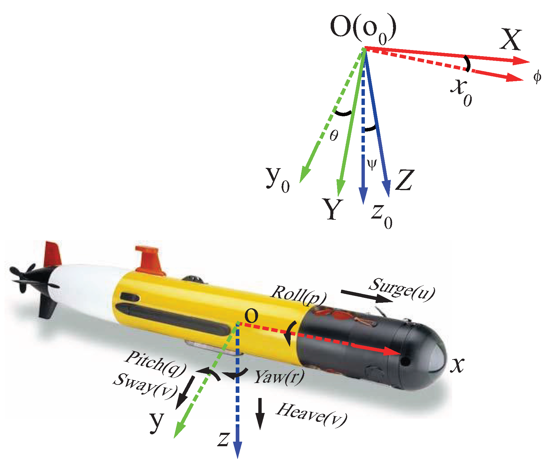
For underwater vehicle, two coordinate systems are usually used for convenience [1]. As shown in Figure 1, is inertial frames in earth (E-frame), and is the coordinate system for a vehicle, which is defined as B-frame. In addition, REMUS 100 vehicle’s states are drawn in Figure 1 and reflected in Table 1. The vehicle has only one propeller fixed in the tail, and four control fins are mounted in the form of a across shape near the tail of the vehicle.
The kinematics transformation between vehicle’s velocity in B-frame and position in E-frame is listed as Equations (1) and (2) [1,28,30].
where , , .
According to the states shown in Table 1 as well as assumptions that the origin of the body frame is at the REMUS vehicle center of buoyancy, the vehicle is treated as a rigid body. The general mathematical descriptions for the motion of the vehicle are listed in Equation (3) [28,30].
In Equation (3), and stand for the gravity and buoyancy center coordinates in vehicle’s B-frame, respectively. m represents the mass of REMUS vehicle.
Hydrostatic force brought by gravity and buoyancy of vehicle, control force of actuator, added mass, hydrodynamic force as well as force and torque generated by the thruster are included in the six DOF nonlinear model of REMUS vehicle. Considering the external forces and torques, we can obtain the exact mathematical expression listed in Equation (4) [30].
where W and B are the gravity and buoyancy of REMUS vehicle. denotes the absolute value of v, and so on for the other state items. The coefficients have been achieved from REMUS vehicle’s experimental data successfully. Explanations and details for coefficients in Equation (4) can be referred to Prestero’s thesis [30]. are the cross flow drag and added mass coefficients in x direction. Similarly, we can have cross flow drag and added mass coefficients for other five directions. It should be noted that stand for resultants of added mass and Fin lift. represent coefficients which take fin lift, body lift force and munk moment into account. are hydrodynamic coefficients related to control fins and thrusters.
Coupling disturbances are the interference of various degrees of freedom in underwater vehicle due to dynamic coupling. Vibrations in the state of one freedom such as pitch channel will bring oscillations for other freedoms such as roll channel, and vice versa. Hence, the vehicle system has to consume more energy to keep the vehicle balanced in the water. In Equation (4), changes in pitch channel are transmitted to the roll by the variation of the pitch angle , the oscillation in p affect items in pitch freedom that are related to the roll rate p and the roll angle (i.e., , , ).
2.2. Pitch Channel Model for REMUS AUV via Taylor Formula Simplification
The nonlinear model of REMUS AUV is examined to evaluate the performance of the proposed control strategy. The actuator of REMUS includes one propeller and four rudders, which are physically restricted to the ranges of 90 degrees. According to models introduced by Prestero [30], the governing equations of pitch channel can be extracted using Equation (5) [4].
where is elevator fins input.
To obtain the equation for control, Equation (5) should be simplified around operating points , , , , using Taylor series, and the linear model is achieved by neglecting high order terms [4,30,31,32]. The simplification model is as follows:
The simplified equation should then be transformed to the state space model with uncertainties added:
where , , and are coefficients of uncertainties associated with u, q, and in nonlinear terms, respectively. In addition, the roll state and p are treated as disturbances in Equation (7). and in Equation (7) are defined below:
Parameters in Equation (7) are time varying, and unknown due to different operating conditions. Linearization approximations and nonlinearities of vehicle actuators also bring additional uncertainties and coupling disturbances. Adaptive control technique is an effective means for dealing with underwater vehicle control with general uncertainties. However, the transient dynamics caused by actuator nonlinearities cannot be handled by adaptive control. A compensator, therefore, should be introduced and integrated with adaptive control such as L1AC. In Section 4, hypothetical linear plant as well as the nonlinear six DOF model of REMUS with uncertainties and nonlinearities of actuator are investigated in the simulation using the proposed approach.
3. Control Strategy
Proper adaptive scheme should be selected to cope with general uncertainties and disturbances, while compensators is employed to improve the transient response. In this section, adaptive control method augmented with a modern AW compensator is presented for systems with uncertainties and input saturation. Firstly, the L1AC is introduced to guarantee fast adaption and robustness. Then, Riccati-based AW compensator is chosen to augment the L1AC architecture to cope with input saturation.
3.1. L1 Adaptive Control
Attempting to address limitations associated with MRAC, L1AC architecture was proposed by Hovakimyan and Cao [16]. L1AC guarantees transient response via decoupling adaption rate from robustness, and reduces the impact of high-frequency oscillation in the control signal. Adaption gains scheduling is eliminated to ensure fast and smooth convergence. It can be used to deal with rapid changes of the system parameters and environmental disturbances. L1AC is described in detail in the following [16].
The state space system used in L1AC takes the general form with uncertainties:
where , ; is the initial condition with bounded set; A is the plant state matrix; y is the measured output; B and C are vectors defined for actuator and observation; u is an input used to control the plant; is an unknown bounded parameter expressing the efficiency of uncertain command; and is an unclear, nonlinear term representing unmodeled dynamics.
The purpose of this controller is to track the desired with y in the presence of unknown A, and . Considering matrix to express the system matrix and rewrite the nonlinear term in the plant as the following [20]:
where and are unknown varying parameters; is state matrix related with ; and is the norm of . Note that in this section is not the pitch angle defined before.
That provides desired performance in the existence of uncertainties, when the controller tracks the control input signal using a reference system model as described:
where , and are estimated parameters obtained from adaption laws in each iteration.
Then, the error signal of the model is formed using the plant measured states and the estimated ones .
Thus, the error can be used to adapt the parameters via computing adaption laws, where a projection method is employed to ensure the uniform boundedness. Furthermore, the projection operator can maintain stability of closed-loop system and achieve fast adaption. Calculation of adaptive laws is accomplished using equations indicated in Equation (12):
where is the adaption gain. Symmetric and positive definite diagonal matrix P is the algebraic answer to the Lyapunov equation: for any arbitrary symmetric matrix .
Projection operator in Equation (12) is defined:
and
where is a projection tolerance, and is the parameter bound.
Then, the L1AC control signal composed by adding a low pass filter is given in the Laplace domain:
where is a strictly proper transfer function used to filter out high-frequency signal; k is the feedback gain; is the gain applied to the reference signal ; and is the control input used to drive the actuator.
3.2. Augment Adaptive Control with Riccati-Based Anti-Windup Compensator
In this part, a modern anti-windup scheme is extended into the L1AC controller. To strengthen the feasibility of controller implemented in practice, the problem of actuator saturation is considered. Recently, several modern AW compensators have been used to tackle input saturation [22,25]. However, most of the solutions to Linear Matrix Inequality (LMI) are prone to numerical errors due to bad initialization [22]. Moreover, the robustness of AW compensator controller is less concerned. The compensator selected is what can modify the performance of the controller when the saturation takes place. Riccati-based AWs is proposed to reduce the computational burden of solving LMI problem [22,33]. Block diagram of the proposed controller is described in Figure 2.
As shown in the diagram, the compensator produces two different outputs when the saturation of actuator is activated: one is fed back to control law, and the other is utilized to modify the control signal.
The problem of AW compensator is transformed into a state feedback form, and is given by:
where and are two outputs of the AW compensator; is compensator measured output; and F is a free parameter. is necessary to be . Therefore, the problem of designing a full-order AW compensator becomes that of choosing an appropriate state feedback gain matrix, F.
The term is computed in Equation (17):
Considering the saturation of actuator input, the nonlinear function of actuator is
In Equations (17) and (18), is the control signal output of L1AC controller, is the actuator or thrust output signal of compensator, and is the maximum applicable control signal. Specific form of actuator’s output signal is expressed as
Feedback gain vector F obtained by computing the following Riccati equation:
where , W and are the AW compensator parameters. The robust analysis of these parameters has been investigated [22]. In this paper, the Riccati-based AW compensator is augmented into L1AC architecture to modify control signal. The equation for the control law is granted as the following.
where is the input of actuator, and is often defined as .
The L1AC controller is required to satisfy norm condition to ensure the stability of the system, and, when proper feedback gain k and filter can be chosen, the following inequality holds.
where
In Equation (23), is a strictly stable closed-loop filter, and the steady state value of the gain is . A straightforward choice of is to keep a first-order filter, that is
Comparing the two control methods with and without the AW compensator, since and are constant after AW compensator is extended into L1AC, it can be seen that in Equation (23) does not change. Thus, the proposed controller can fulfill norm condition. The compensator will output signals only when is not zero, and the two signals can be used to correct the or compensate the speed q as well as the pitch angle . In Equation (21), the modification for controller is simply achieved through replacing with in adaption law and control law. The stability of L1AC controller can be ensured because the value of the control law given by the Equation (21) is always less than , which means the set of u is a subset of the set of . The model of REMUS and linear system model for control has been introduced in Section 2. In Section 4, this controller is implemented in REMUS underwater vehicle. As shown in Figure 2, L1AC with AW compensator approach is utilized to control the pitch channel of REMUS vehicle with desired set-points .
4. Results and Discussion
Models oriented for adaptive control are obtained from simplification of the nonlinear model. However, the performance of vehicle controllers is susceptible to actuator nonlinearities and uncertainties in the model. In this section, the kinetic characteristics of the REMUS vehicle in roll mode and the hydrostatics are studied. Then, simulations are conducted using different plant models of underwater vehicle obtained using methods mentioned in the previous Section 2. In addition, tracking performances of controllers with or without AW compensator are compared in this section.
4.1. Model Characteristics
Considering the input limitation in physical space and requirements of input instructions, the input range of the actuator should be smaller than the maximum operating range. The parameters of L1AC controller and AW compensator for REMUS pitch channel differ due to different types of plant model employed. All coefficients for REMUS AUV are all obtained from Prestero’s thesis [30].
In realistic experiment, roll angle of the vehicle is not zero due to the moment of the propeller. Thus, the pitch motion controlled with horizontal rudders is coupled with roll angle and roll rate. The linear plant model is derived under the assumptions that pitch motion of REMUS is independent, which brings more certainties for vehicle control. The roll angle of the REMUS vehicle running in steady conditions is observed to have an average roll offset of about −5.3 degrees when the pitch angle is zero. The roll channel is coupled with pitch channel in practice, and the fluctuation in the roll channel will magnify the value of the disturbance. Therefore, coupling perturbations must be treated properly.
Figure 3 depicts the roll angle and rate response of REMUS vehicle when propeller force is 3.86 N, and propeller torque is −0.534 Nm. The roll channel is coupled with REMUS vehicle’s other freedoms, which can be treated as a disturbance in pitch motion control. Note that the coupled relationship between roll rate and actuators allows us to focus on the frequency and amplitude of the rudders of the underwater vehicle. In addition, the rate of roll should be confined in a small range to suppress coupling disturbances in vehicle systems when controller is working.
Underwater vehicle’s buoyancy varies in different density of the water environment, which brings two effects: uncertainty and steady-state error. Uncertainty in system dynamic due to the water density changes, together with water flow [19], can be predicted using adaptive law. The buoyancy changes of underwater vehicle make it a static instability system. However, the REMUS vehicle is an under-actuated system and only the horizontal rudder can be used to adjust the pitch angle of the underwater vehicle model with positive buoyancy. Part of the forces and moments resulted from the horizontal rudder is used to balance the positive buoyancy force of the vehicle. This can help explain why there is a steady-state error in pitch channel control. Figure 4 shows the relationship between steady-state error and underwater robot buoyancy.
4.2. Conditions and Parameters
Linear system plant with uncertainties and unknown parameters is mostly utilized in adaptive control, but neither the influence of roll angle offset nor the effect of the hydrostatics is considered in most studies. The hypothetical linear model for pitch channel is determined with and . To signify the shortcoming of L1AC controller in the presence of input limitations, performances of L1AC and our proposed controller are compared in the following with and . The parameters for compensator are listed: , , . In the case of linear plant for pitch channel, the input saturation for elevator angles is restricted from to 20 degrees owing to the effectiveness of input values within physical space.
4.3. Control Experiments Comparison
In Figure 5, pitch angle, rate and control signals for L1AC and our proposed controller are compared in the presence of model uncertainties and bounded disturbances.
L1AC and the proposed method can both adapt to time-varying inaccurate model parameters of vehicle, but the performance of L1AC with AW compensator surpasses L1AC in performance, which verifies the capability of L1AC with AW compensator controller. It should be noted that the proposed controller can make better use of the potential of the actuator of the vehicle and reduce the fluctuation of pitch rate q and roll rate p. The coupling disturbance between roll channel and pitch channel is suppressed, thus the desired set-points can be achieved at lower cost of energy.
The six DOF model of REMUS vehicle is a system with strong nonlinearities. It cannot keep steady in the water due to gravity and buoyancy when the system shut down, which brings more uncertainties to the control. In the case of pitch control for REMUS vehicle, the input saturation for elevator angles is restricted from to , where is the input signal from horizontal rudders when pitch angle of REMUS vehicle is zero. In the simulation, is , which is extracted from the instruction database and the status measurements when underwater vehicle navigates in the water.
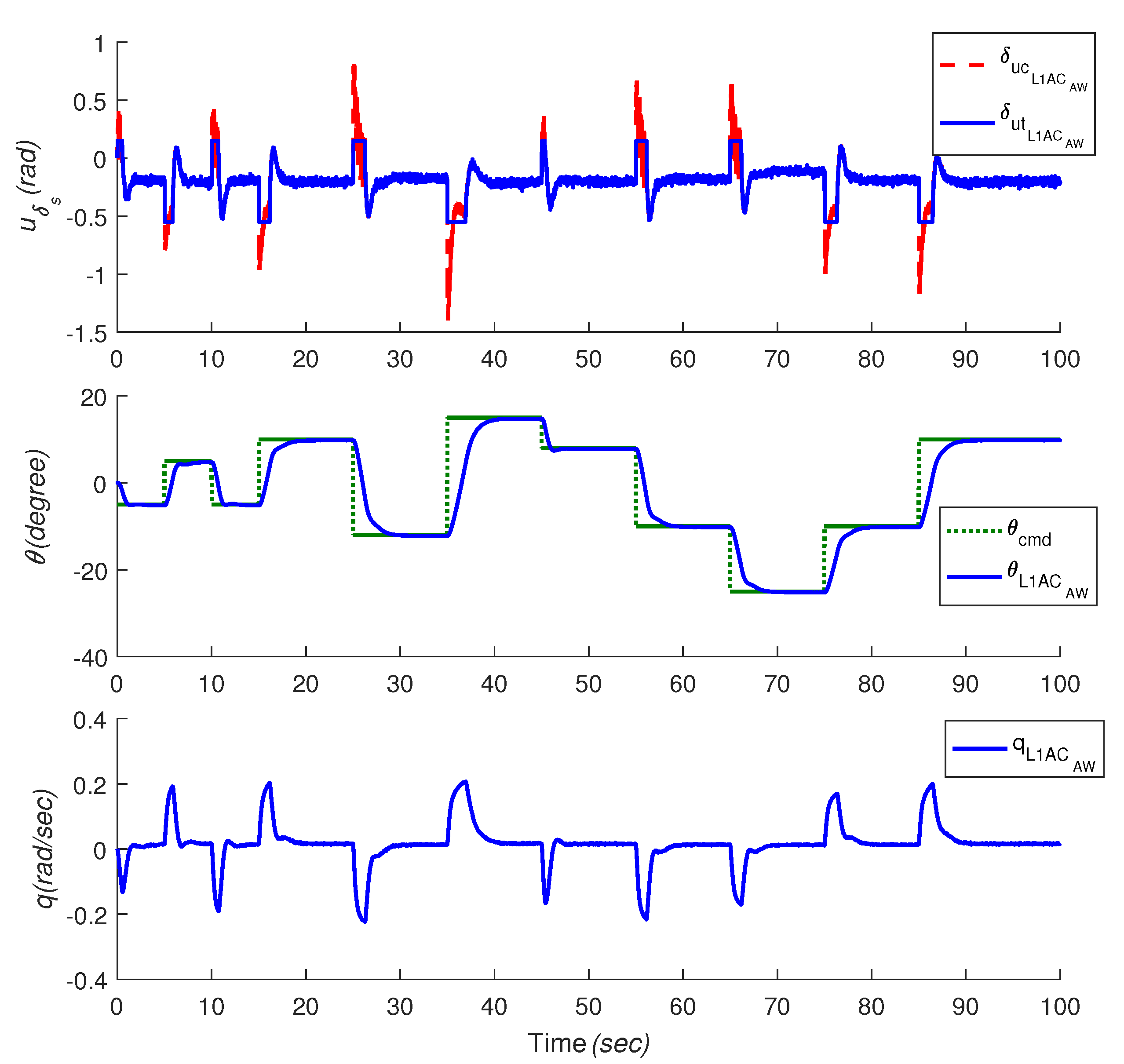
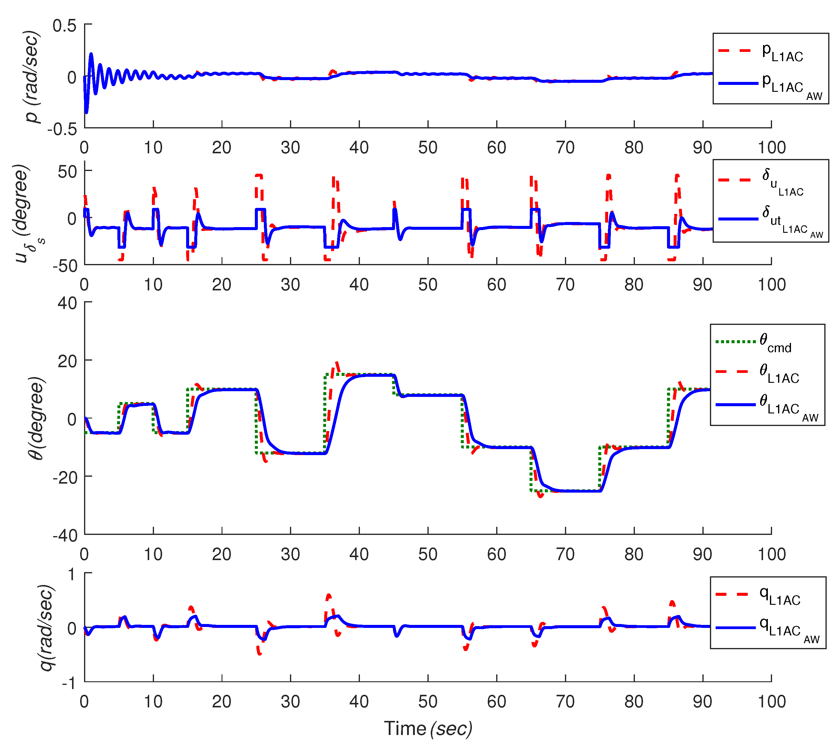
In view of the battery life and overall stability of the vehicle system control, the input signal should be deliberated. As seen in Figure 6 and Figure 7, the overall performance of L1AC can be improved with AW compensator compared with L1AC via exploiting the potential of propeller within the permissible range when there is an input constraint. Unexpected fluctuations in control signals, pitch angle and roll rate p caused by tracking instructions, disturbances, unknown model uncertainties and system coupling effects can be weakened. It should be noted that the overall stability of L1AC controller will not be affected by the compensator augmented according to Figure 5, Figure 6 and Figure 7. From the viewpoint of energy conservation, the adaptive control method with a compensator can moderately suppress the coupling disturbance (i.e., roll rate) of the underwater robot and reduce the energy loss.
Furthermore, the nonlinear six DOF model of REMUS AUV is considered to track a desired pitch angle aiming to further investigate the realistic performance of our proposed approach. As seen in Figure 8, although the roll angle fluctuation exists in the six DOF model simulation, the L1AC controller with AW compensator can cope with actuator nonlinearities and improve the performances of control signal as well as pitch angle tracking results when the disturbance of actuator (height of Power Spectral Density (PSD) is ), measurement noises (heights of PSD are [, ]) and input time-delay (the value is 0.01 s) are considered, which reveals that the introduced control strategy is appropriate to control the motion of vehicle with model uncertainties and actuator limitations in control practice.
5. Conclusions
In this paper, a control strategy is put forward to deal with challenges in underwater vehicle control practice. Considering unmodeled uncertainties and coupling disturbances in underwater vehicle system, adaptive control is employed as the control architecture to guarantee robustness and fast adaption. A modern compensator based on Riccati equation is combined with adaptive control to deal with the transient dynamics caused by input nonlinearities. The proposed method is successfully applied to the pitch channel of REMUS vehicle model. REMUS model is a six DOF nonlinear dynamic model extracted from experimental data. The pitch channel control vehicle is systematically coupled with other degrees of freedom. In this paper, the performance of the proposed control method is studied by tracking the desired command in several scenarios. Results show that adaptive control with Riccati based AW compensator can tackle input saturation in practice as well as adapt to model uncertainties, coupling disturbances and noise. Hence, the proposed control scheme could be considered as a candidate for control practice on the physical platform in the future.
Acknowledgments
This work is supported by the National Natural Science Foundation of the National Research and Development of major scientific instruments (41427806), ROV System For Exploration and Sampling (DY125-21-Js-06) funded by the State Oceanic Administration People’s Republic Of China and National High Technology Research and Development Program of China (863 Program, Grant No. 2012AA092103). The authors would also like to express their appreciation to LW Yu and P Sarhadi for their great help on completing this work successfully.
Author Contributions
Nailong Wu put forward the original concept, proposed the control approach and wrote the article. Chao Wu, Tong Ge, and Deqing Yang gave their valuable suggestions on research design. Besides, Nailong Wu, Chao Wu, along with Rui Yang, analyzed and discussed the simulation results.
Conflicts of Interest
The authors declare no conflict of interest.
References
- Fossen, T.I. Guidance and Control of Ocean Vehicles; John Wiley & Sons Inc.: Chichester, UK, 1994. [Google Scholar]
- Cui, R.; Zhang, X.; Cui, D. Adaptive sliding-mode attitude control for autonomous underwater vehicles with input nonlinearities. Ocean Eng. 2016, 123, 45–54. [Google Scholar] [CrossRef]
- Li, H.; Jing, X.; Karimi, H.R. Output-feedback-based H∞ control for vehicle suspension systems with control delay. IEEE Trans. Ind. Electron. 2014, 61, 436–446. [Google Scholar] [CrossRef]
- Sarhadi, P.; Noei, A.R.; Khosravi, A. Model reference adaptive pid control with anti-windup compensator for an autonomous underwater vehicle. Robot. Auton. Syst. 2016, 83, 87–93. [Google Scholar] [CrossRef]
- Hassanein, O.; Anavatti, S.G.; Shim, H.; Ray, T. Model-based adaptive control system for autonomous underwater vehicles. Ocean Eng. 2016, 127, 58–69. [Google Scholar] [CrossRef]
- Lavretsky, E.; Gadient, R.; Gregory, I.M. Predictor-based model reference adaptive control. J. Guid. Control Dyn. 2010, 33, 1195–1201. [Google Scholar] [CrossRef]
- Lavretsky, E.; Wise, K. Robust and Adaptive Control with Aerospace Applications; Springer: London, UK, 2013. [Google Scholar]
- He, W.; Dong, Y.; Sun, C. Adaptive neural impedance control of a robotic manipulator with input saturation. IEEE Trans. Syst. Man Cybern. Syst. 2016, 46, 334–344. [Google Scholar] [CrossRef]
- He, W.; Chen, Y.; Yin, Z. Adaptive neural network control of an uncertain robot with full-state constraints. IEEE Trans. Cybern. 2016, 46, 620–629. [Google Scholar] [CrossRef] [PubMed]
- Xiao, B.; Yin, S.; Kaynak, O. Tracking control of robotic manipulators with uncertain kinematics and dynamics. IEEE Trans. Ind. Electron. 2016, 63, 6439–6449. [Google Scholar] [CrossRef]
- He, W.; Kong, L.; Dong, Y.; Yu, Y.; Yang, C.; Sun, C. Fuzzy tracking control for a class of uncertain mimo nonlinear systems with state constraints. IEEE Trans. Syst. Man Cybern. Syst. 2017, 1–12. [Google Scholar] [CrossRef]
- Nicholas, L.T.; Valladarez, D.; Du Toit, N.E. Robust adaptive control of underwater vehicles for precision operations. In Proceedings of the OCEANS’15 MTS/IEEE, Washington, DC, USA, 19–22 October 2015; pp. 1–7. [Google Scholar]
- Wang, H.; Chen, B.; Liu, X.; Liu, K.; Lin, C. Robust adaptive fuzzy tracking control for pure-feedback stochastic nonlinear systems with input constraints. IEEE Trans. Cybern. 2013, 43, 2093–2104. [Google Scholar] [CrossRef] [PubMed]
- Wang, H.; Liu, X.; Liu, K. Adaptive neural data-based compensation control of non-linear systems with dynamic uncertainties and input saturation. IET Control Theory Appl. 2015, 9, 1058–1065. [Google Scholar] [CrossRef]
- Sarhadi, P.; Noei, A.R.; Khosravi, A. Adaptive integral feedback controller for pitch and yaw channels of an auv with actuator saturations. ISA Trans. 2016, 65, 284–295. [Google Scholar] [CrossRef] [PubMed]
- Hovakimyan, N.; Cao, C. L1 Adaptive Control Theory: Guaranteed Robustness with Fast Adaptation; SIAM: Philadelphia, PA, USA, 2010. [Google Scholar]
- Wang, X.; Hovakimyan, N. L1 adaptive controller for nonlinear reference systems. In Proceedings of the American Control Conference (ACC), San Francisco, CA, USA, 29 June–1 July 2011; pp. 594–599. [Google Scholar]
- Kharisov, E.; Hovakimyan, N.; Åström, K.J. Comparison of architectures and robustness of model reference adaptive controllers and L1 adaptive controllers. Int. J. Adapt. Control Signal Process. 2014, 28, 633–663. [Google Scholar] [CrossRef]
- Maalouf, D.; Chemori, A.; Creuze, V. Stability analysis of a new extended L1 controller with experimental validation on an underwater vehicle. In Proceedings of the 2013 IEEE 52nd Annual Conference on Decision and Control (CDC), Florence, Italy, 10–13 December 2013; pp. 6149–6155. [Google Scholar]
- Maalouf, D.; Chemori, A.; Creuze, V. L1 adaptive depth and pitch control of an underwater vehicle with real-time experiments. Ocean Eng. 2015, 98, 66–77. [Google Scholar] [CrossRef]
- Maalouf, D.; Creuze, V.; Chemori, A. A novel application of multivariable L1 adaptive control: From design to real-time implementation on an underwater vehicle. In Proceedings of the 2012 IEEE/RSJ International Conference on Intelligent Robots and Systems(IROS), Vilamoura-Algarve, Portugal, 7–11 October 2012; pp. 76–81. [Google Scholar]
- Sofrony, J.; Turner, M.C.; Postlethwaite, I. Anti-windup synthesis using riccati equations. Int. J. Control 2007, 80, 112–128. [Google Scholar] [CrossRef]
- Yin, S.; Gao, H.; Qiu, J.; Kaynak, O. Adaptive Fault-Tolerant Control for Nonlinear System With Unknown Control Directions Based on Fuzzy Approximation. IEEE Trans. Syst. Man. Cybern. Syst. 2017, 47, 1909–1918. [Google Scholar] [CrossRef]
- Yin, S.; Gao, H.; Qiu, J.; Kaynak, O. Fault detection for nonlinear process with deterministic disturbances: A just-in-time learning based data driven method. IEEE Trans. Cybern. 2017, 47, 3649–3657. [Google Scholar] [CrossRef] [PubMed]
- Oliveira, M.Z.; da Silva, J.M.G.; Coutinho, D.; Tarbouriech, S. Design of anti-windup compensators for a class of nonlinear control systems with actuator saturation. J. Control Autom. Electr. Syst. 2013, 24, 212–222. [Google Scholar] [CrossRef]
- Sarhadi, P.; Ranjbar Noei, A.; Khosravi, A. L1 adaptive pitch control of an autonomous underwater vehicle. Int. J. Intell. Unmanned Syst. 2014, 2, 107–120. [Google Scholar] [CrossRef]
- Valladarez, ND. An Adaptive Approach for Precise Underwater Vehicle Control in Combined Robot-Diver Operations. Master Thesis, Naval Postgraduate Naval Postgraduate School, Monterey, CA, USA, 2015. [Google Scholar]
- Prestero, T. Development of a six-degree of freedom simulation model for the REMUS autonomous underwater vehicle. In Proceedings of the OCEANS, MTS/IEEE Conference and Exhibition, Honolulu, HI, USA, 5–8 November 2001; Volume 1, pp. 450–455. [Google Scholar]
- Sarhadi, P.; Yousefpour, S. State of the art: Hardware in the loop modeling and simulation with its applications in design, development and implementation of system and control software. Int. J. Dyn. Control 2015, 3, 470–479. [Google Scholar] [CrossRef]
- Prestero, T. Verification of a Six-Degree of Freedom Simulation Model for the Remus Autonomous Underwater Vehicle. Master Thesis, Massachusetts Institute of Technology, Cambridge, MA, USA, 2001. [Google Scholar]
- Wu, N.L.; Wang, X.Y.; Ge, T.; Wu, C.; Yang, R. Parametric identification and structure searching for underwater vehicle model using symbolic regression. J. Mar. Sci. Technol. 2016, 1, 51–60. [Google Scholar] [CrossRef]
- Yang, R.; Clement, B.; Mansour, A.; Li, M.; Wu, N. Modeling of a complex-shaped underwater vehicle for robust control scheme. J. Intell. Robot. Syst. 2015, 80, 491–506. [Google Scholar] [CrossRef]
- Yang, S.-K. Observer-based anti-windup compensator design for saturated control systems using an LMI approach. Comput. Math. Appl. 2012, 64, 747–758. [Google Scholar] [CrossRef]
Figure 1.
REMUS body frame and inertial reference frame.

Figure 2.
Block diagram of L1AC with AW compensator for REMUS AUV in pitch channel.

Figure 3.
Roll angle and rate p of REMUS in six DOF model simulation.

Figure 4.
Relationship between the buoyancy and the steady-state error.
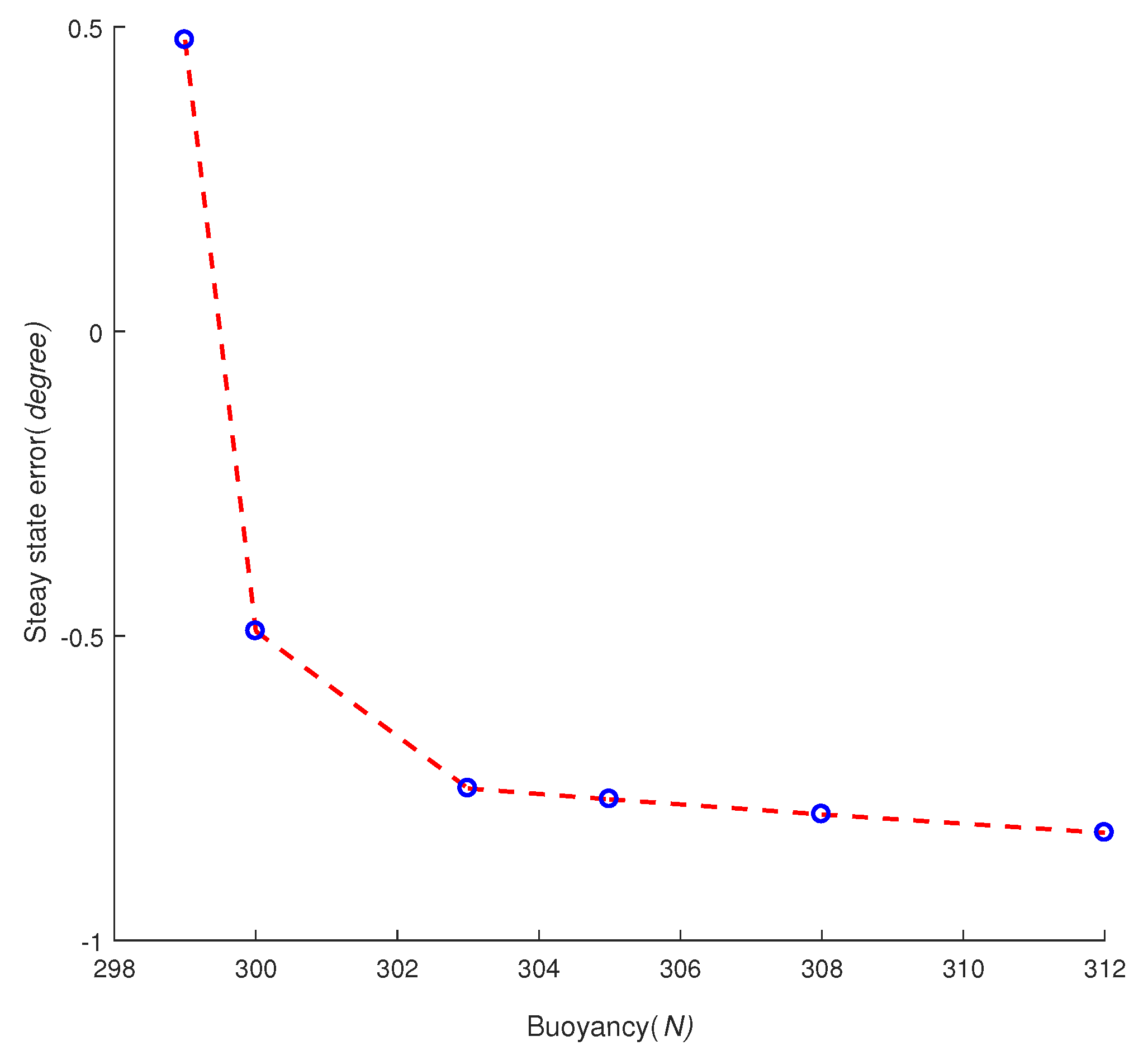
Figure 5.
Pitch channel control in the presence of the actuator saturation for linear plant tracking (pulse signal).
Figure 5.
Pitch channel control in the presence of the actuator saturation for linear plant tracking (pulse signal).

Figure 6.
Pitch channel control in the presence of the actuator saturation for REMUS six DOF model tracking (pulse signal).
Figure 6.
Pitch channel control in the presence of the actuator saturation for REMUS six DOF model tracking (pulse signal).
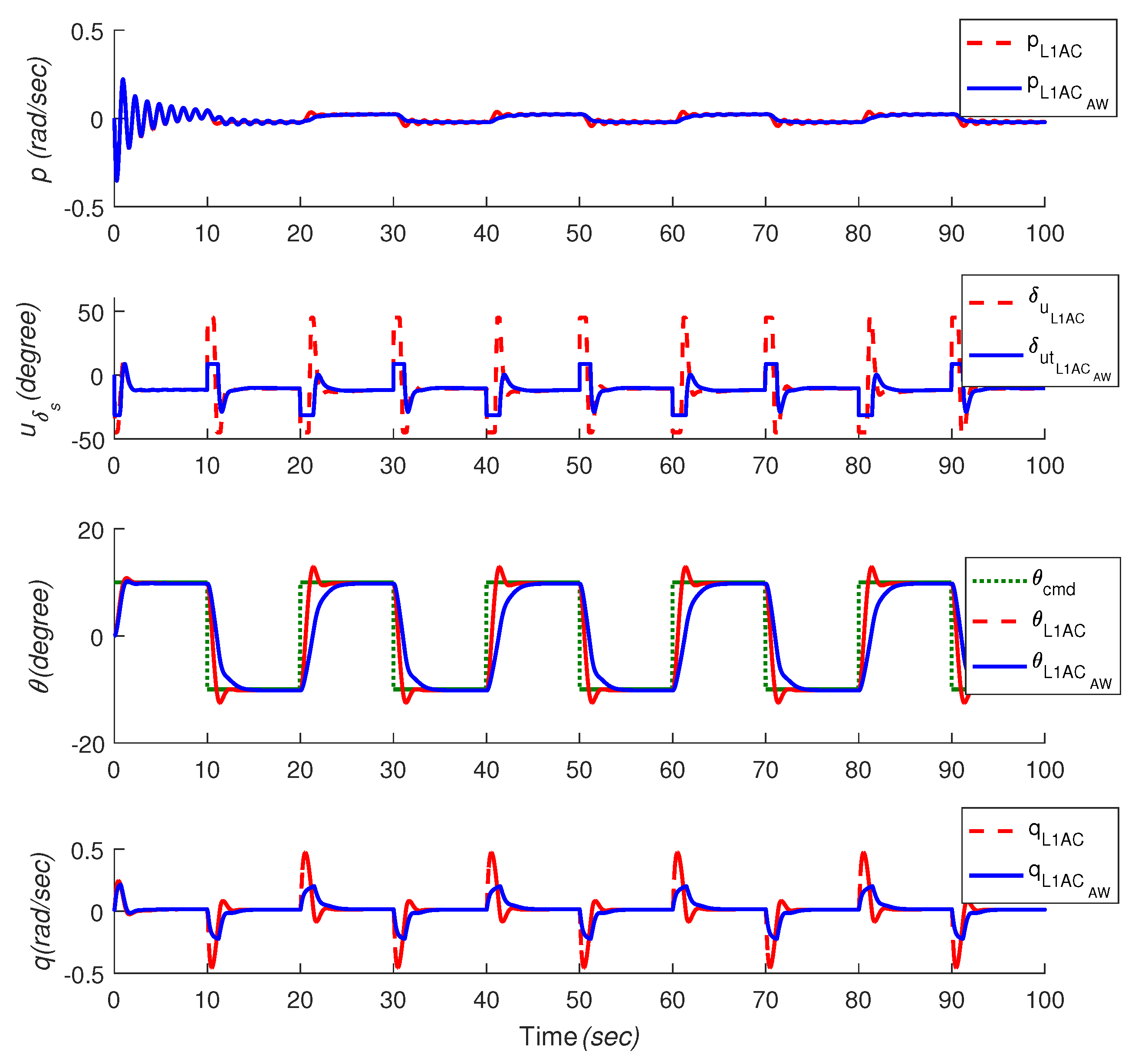
Figure 7.
Pitch channel control in the presence of the actuator saturation for REMUS six DOF model tracking with different set-points.
Figure 7.
Pitch channel control in the presence of the actuator saturation for REMUS six DOF model tracking with different set-points.

Figure 8.
Pitch channel control in the presence of the actuator saturation for REMUS six DOF model tracking with different set-points with measurement noise, elevator disturbance and input time-delay.
Figure 8.
Pitch channel control in the presence of the actuator saturation for REMUS six DOF model tracking with different set-points with measurement noise, elevator disturbance and input time-delay.

Table 1.
Notations for Underwater vehicle.
| Coordinate | Position & Angles E-Frame | Linear & Angular Velocities B-Frame | Forces & Moments B-Frame |
|---|---|---|---|
| Surge | X | u | |
| Sway | Y | v | |
| Heave | Z | w | |
| Roll | p | ||
| Pitch | q | ||
| Yaw | r |
© 2018 by the authors. Licensee MDPI, Basel, Switzerland. This article is an open access article distributed under the terms and conditions of the Creative Commons Attribution (CC BY) license (http://creativecommons.org/licenses/by/4.0/).
Share and Cite
MDPI and ACS Style
Wu, N.; Wu, C.; Ge, T.; Yang, D.; Yang, R. Pitch Channel Control of a REMUS AUV with Input Saturation and Coupling Disturbances. Appl. Sci. 2018, 8, 253. https://doi.org/10.3390/app8020253
AMA Style
Wu N, Wu C, Ge T, Yang D, Yang R. Pitch Channel Control of a REMUS AUV with Input Saturation and Coupling Disturbances. Applied Sciences. 2018; 8(2):253. https://doi.org/10.3390/app8020253
Chicago/Turabian StyleWu, Nailong, Chao Wu, Tong Ge, Deqing Yang, and Rui Yang. 2018. "Pitch Channel Control of a REMUS AUV with Input Saturation and Coupling Disturbances" Applied Sciences 8, no. 2: 253. https://doi.org/10.3390/app8020253
Note that from the first issue of 2016, this journal uses article numbers instead of page numbers. See further details here.