1. Introduction
Induction machine (IM) drives [
1,
2] have been widely utilized in motion control applications such as the speed control of a pump, or a machine tool, or an electric vehicle, etc. (e.g., [
3,
4]). To achieve high servo quality, many studies (e.g., [
5,
6]) have been focused on the speed control of a direct-field-oriented (DFO) IM. However, additional design efforts for decoupling the torque and flux control of a DFO IM are required. Additionally, the decoupling control is vulnerable to adverse load disturbances and parameter variations which can severely degrade tracking performance. In comparison, the speed controller design for a voltage/frequency (V/f) controlled IM is generally much simpler than that for a DFO IM. Accordingly, this paper adopts a V/f controlled IM framework for speed control.
In motion control applications, it is desirable that a controlled IM should closely follow a reference speed trajectory in situations with or without torque disturbances. Though the system stability may be guaranteed by using the conventional proportional-integral (PI) or proportional-integral-derivative (PID) speed controllers (e.g., [
7]) with well-chosen parameter values, the robustness to abrupt load changes in the motor may not be improved. This difficulty may be overcome by using a model-based predictive control strategy (e.g., [
5,
6,
8]), an adaptive backstepping method (e.g., [
9]), a descriptor approach (e.g., [
10]), a composite nonlinear feedback control scheme (e.g., [
11]), or a
output-feedback control method (e.g., [
12]). However, the control performance relies on how well the system is described by the model. Accordingly, the incorporation of machine intelligence into the control of IM drives has been widely used as a viable alternative for improving the system stability, performance and robustness. Specifically, intelligent controllers for IM drives have been proposed based on fuzzy logic (e.g., [
13,
14,
15]) or neural networks (e.g., [
16]) or neuro-fuzzy inferences (e.g., [
17,
18,
19]) or a particle swarm optimization algorithm (e.g., [
3]). Based on the use of a fuzzy controller for adaptively adjusting PID parameter values, a fuzzy P+ID controller in [
20], a fuzzy PI self-tuning controller in [
21,
22,
23] and a fuzzy self-tuning fuzzy PID controller in [
24,
25] may also be employed. In addition, a fuzzy model-based predictive control strategy (e.g., [
26]) may be utilized. Nevertheless, the aforementioned controller structures did not investigate a control scheme composed of a fixed-gain PI or PID in combination with a fuzzy-logic controller (FLC). Thus, a Ziegler-Nichols (Z-N) PID (e.g., [
27]) in tandem with a FLC was proposed in [
28] for the control of a DFO IM. Unlike best trial-and-error PI or PID controllers, the foregoing intelligent controllers can adaptively mitigate the adverse effects of torque disturbances and achieve desirable performance.
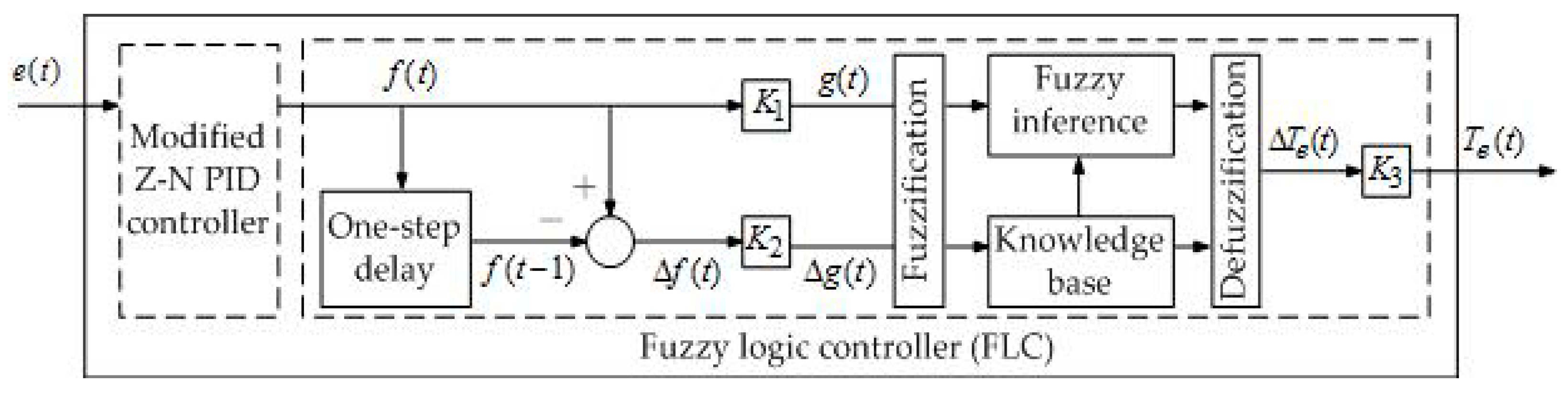
The first objective of this paper is to present an intelligent control scheme which has simple design and satisfactory performance for robust speed control of a V/f controlled IM. In this regard, we propose a modified Z-N PID+Fuzzy controller, which consists of a fixed-gain modified Z-N PID in [
29] together with an FLC. Our proposed approach is distinct from other schemes (e.g., [
30,
31,
32]). The modified Z-N PID is adopted because it can outperform the Z-N PID. Like the Z-N PID+Fuzzy in [
28], the modified Z-N PID and the FLC of the proposed controller are connected in tandem. We design an adequate FLC, distinct from the FLC in [
28,
33] in membership functions, based on the output signal of the modified Z-N PID. The FLC gives adequate torque commands which in turn yield appropriate stator frequency commands for controlling the speed of the IM. Meanwhile, the FLC does not tune PID parameter values.
The second objective of this paper is to feasibly achieve low-cost control implementation. In this regard, we propose an Arduino rather than a Field-Programmable Gate Array (FPGA) (e.g., [
34,
35,
36,
37]) for the implementation of the proposed speed controller. Our main reasons for this choice are given as follows. Firstly, the use of a software programming language to develop a control scheme is simpler and more user-friendly than that of a hardware description language. Secondly, the use of an Arduino may save more computational resources. Thirdly, an Arduino is much more economical than an FPGA.
The advantages of the proposed control scheme for speed tracking of a V/f controlled Nikki Denso NA21-3F 0.14-hp squirrel-cage IM are evaluated. Despite various motor horsepower, induction motors have a similar internal functional structure. Thus, a control design methodology for the 0.14-hp induction motor is in general applicable to the control design of induction motors with larger horsepower. Experiments with/without load torque disturbances are performed by PC-based and Arduino-based control. The PC and the Arduino plus the circuits which we design cost around US $600.00 and US $32.00, respectively. The experimental results consistently demonstrate that the proposed scheme can noticeably outperform several control schemes such as a Z-N PID and a modified Z-N PID in speed tracking and robustness. It is noted that the Arduino-implemented modified Z-N PID+Fuzzy for speed control of the V/f controlled IM yields slightly higher tracking errors than the PC-based modified Z-N PID+Fuzzy. Nevertheless, the Arduino-implemented controller is preferable in consideration of price, size, and robust tracking performance.
The outline of this paper is as follows.
Section 2 describes the framework for speed control of a V/f controlled IM.
Section 3 presents the proposed intelligent control method. The experimental setups are described in
Section 4. The experimental results of PC- and Arduino-implementation of the proposed control design method and other schemes are provided. Conclusions are given in
Section 5.
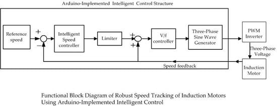
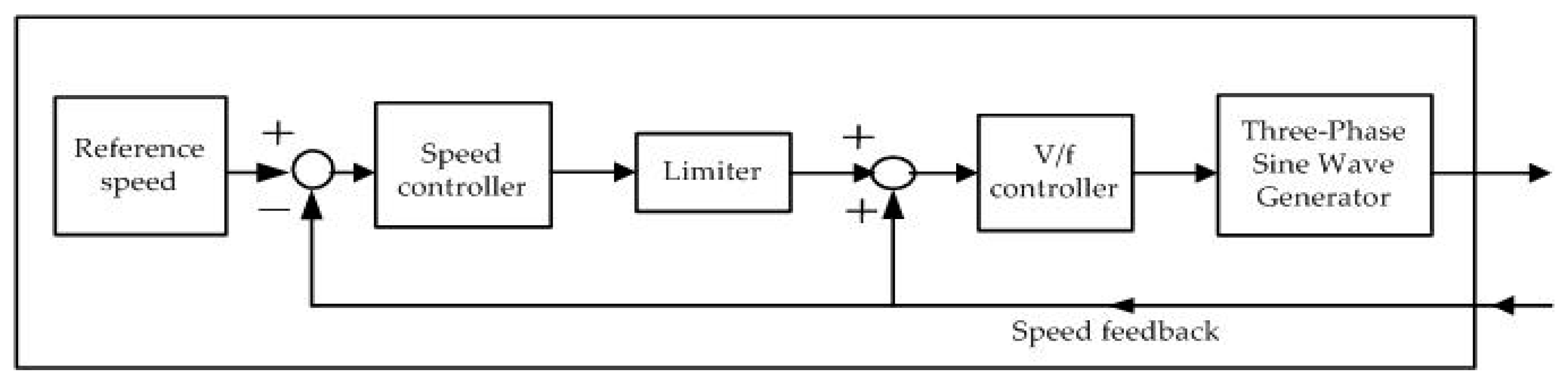
2. System Description
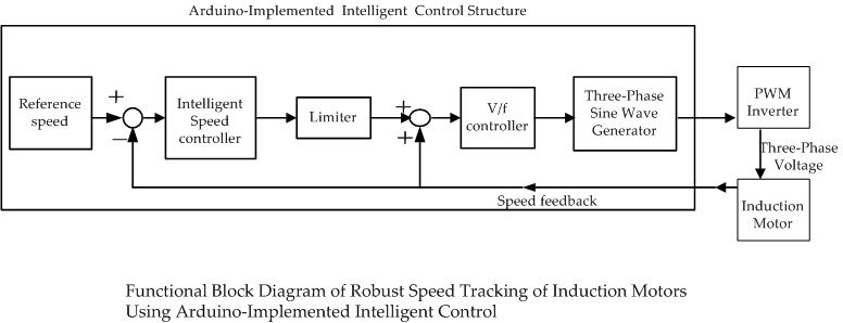
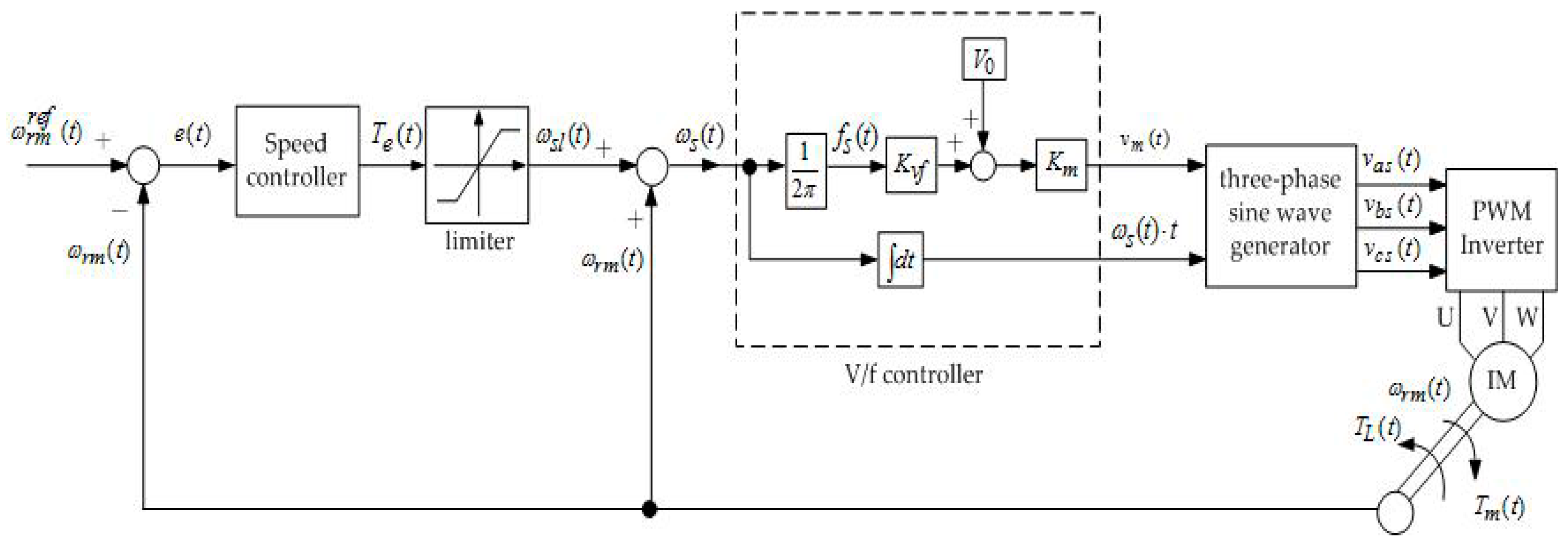
For the velocity control of the V/f controlled IM, the system mainly consists of three parts: IM, V/f controller and speed controller. The block diagram of the closed-loop system structure is shown in
Figure 1 (cf. Figure 7.18 in [
2]).
For the IM, its input phase voltages are transformed from three-phase stator rms voltage inputs
,
and
, which are generated by the outputs of the V/f controller via a three-phase sine wave generator as follows:
where
and
denote the supply voltage and the electrical angular velocity, respectively. A simplified IM model represented by the input–output relation between the electromagnetic torque
and the mechanical angular velocity
(rad/s) can be written as
where
represents an external load torque;
and
stand for the rotor inertia and the coefficient of viscous damping, respectively.
For the V/f controller, its inputs are
and
, which stand for a stator frequency command (Hz) and an offset voltage to counter the stator resistive voltage drop, respectively. The stator frequency command is set as
where
is the slip speed. The outputs of the V/f controller are
and
. The input and output relations are given by
and
where
is a constant ratio between the stator-phase voltage and the stator frequency, and
is a constant gain.
For the speed controller, its input is the difference error
and its output is the control command
where
denotes the reference speed (rad/s). The input of the limiter is
and its output is given by
where
denotes the rotor resistance;
and
stand for the stator and rotor inductances, respectively.
4. Experimental Study
The experimental tests are performed on a Nikki Denso NA21-3F 0.14-hp induction motor. We carry out various PC- and Arduino-implemented experimental tests on the performance of the proposed method and other controller schemes. The experimental results consistently confirm that the proposed modified Z-N PID+Fuzzy method can give noticeable robustness and improvements over other schemes tested. In addition, it is demonstrated that the proposed low-cost Arduino-implemented control scheme can feasibly and effectively yield satisfactory robust performance though it gives slightly higher tracking errors than the proposed PC-based counterpart.
4.1. Experimental Setup
For the V/f controller in
Figure 1, the parameter values are set as follows:
,
and
In accordance with the information in the specification and instruction manual of the Nikki Denso NA21-3F 0.14-hp induction motor, the motor parameter values in Equations (4) and (9) are given by
(kg·cm·s
2),
(g·cm/rpm),
and
.
To obtain various speed controllers, we use the Matlab/Simulink software and the system functional structure in
Figure 1 to develop a computer simulation model in which the three-phase induction motor is used with parameters provided as above, and no external load torque is applied. To obtain a Z-N PID and a modified Z-N PID, we first employ a linear proportional speed controller in the simulation model. Next, a step input is applied, and the proportional gain is adjusted until the system reaches the stability limit. However, no critical oscillation takes place at the system output; only system output divergence can occur. Therefore, we adapt the design steps described in [
29] and in
Section 3.1 to obtain the critical gain and the critical time period. In practice, we increase the gain, and get the approximate critical gain
with which the system diverges immediately at the approximate time 0.049 s. Then, we take
. This together with the formula in [
27], the Z-N PID is given by
. Moreover, based on Equations (10)–(12) with
and
= −135°, the modified Z-N PID is given by
.
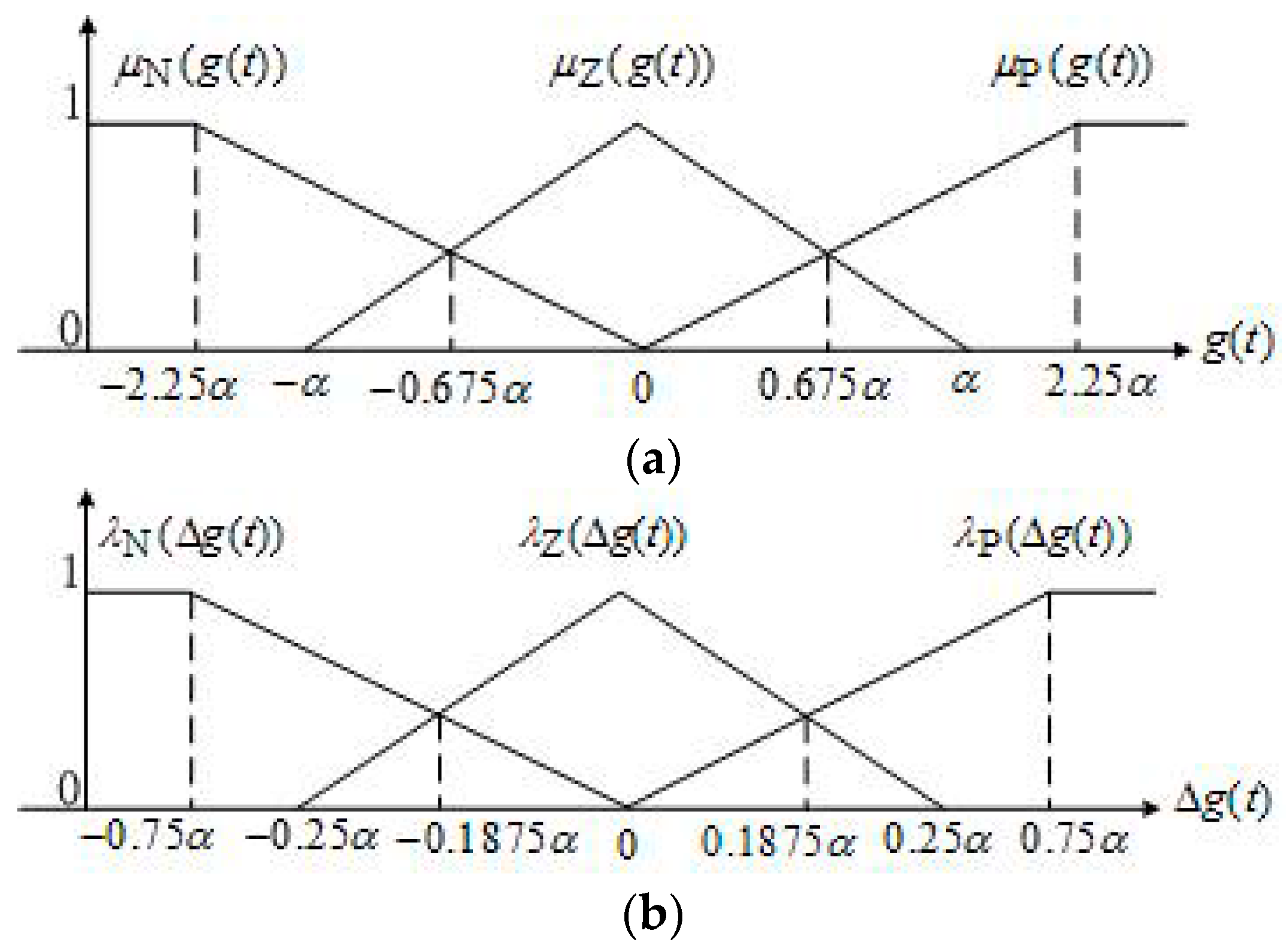
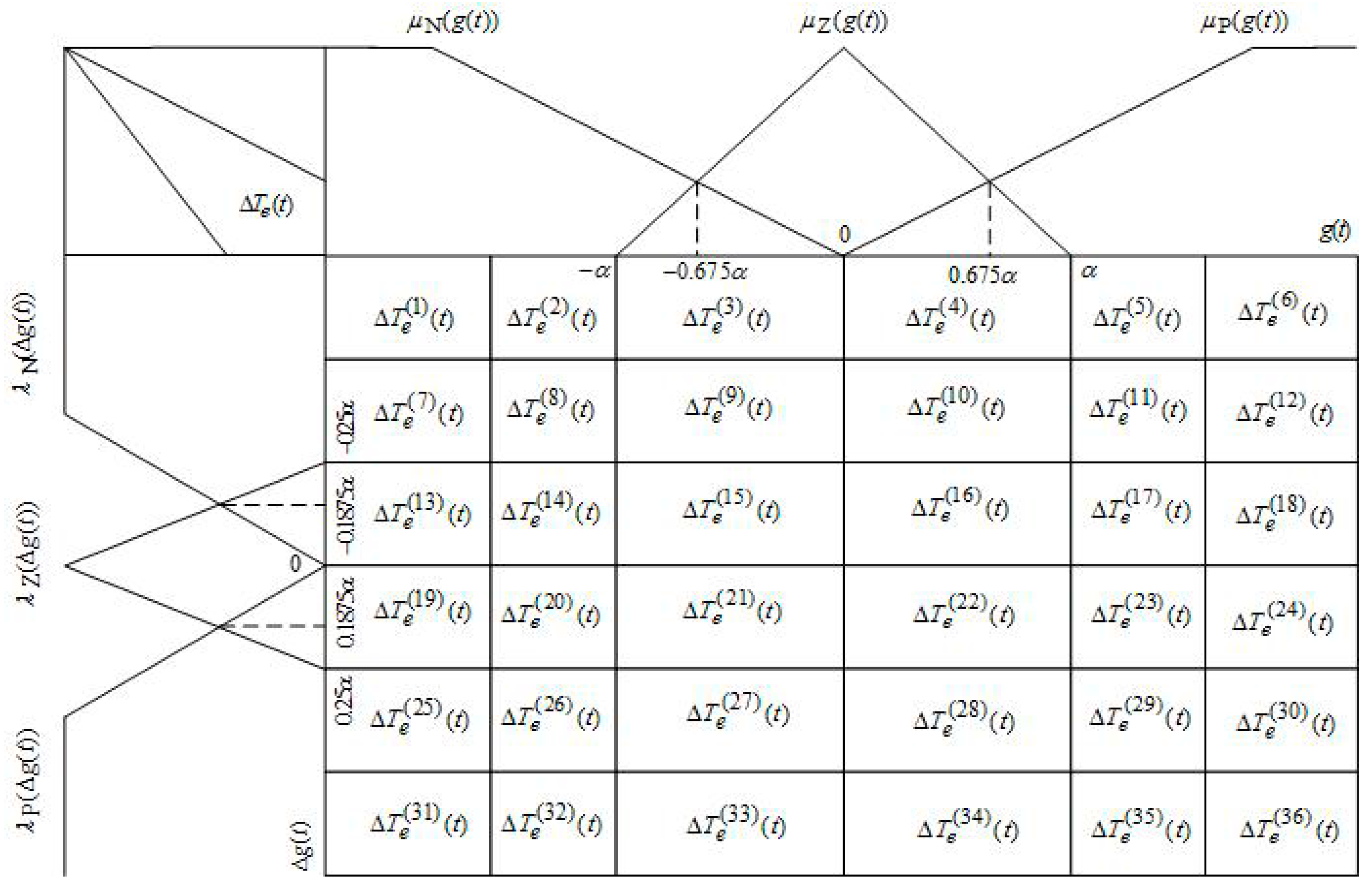
To obtain a desirable FLC for the modified Z-N PID+Fuzzy, we first heuristically set the parameter values and . Next, we use Equations (14)–(23) and adjust the values of the parameters and until closed-loop system responses of the Matlab/Simulink computer simulation model under no torque disturbance are satisfactory. As a result, we get and .
The experimental tests are carried out using the PC-based and the Arduino-based control schemes. In addition, all speed controllers obtained above are employed in the experimental tests.
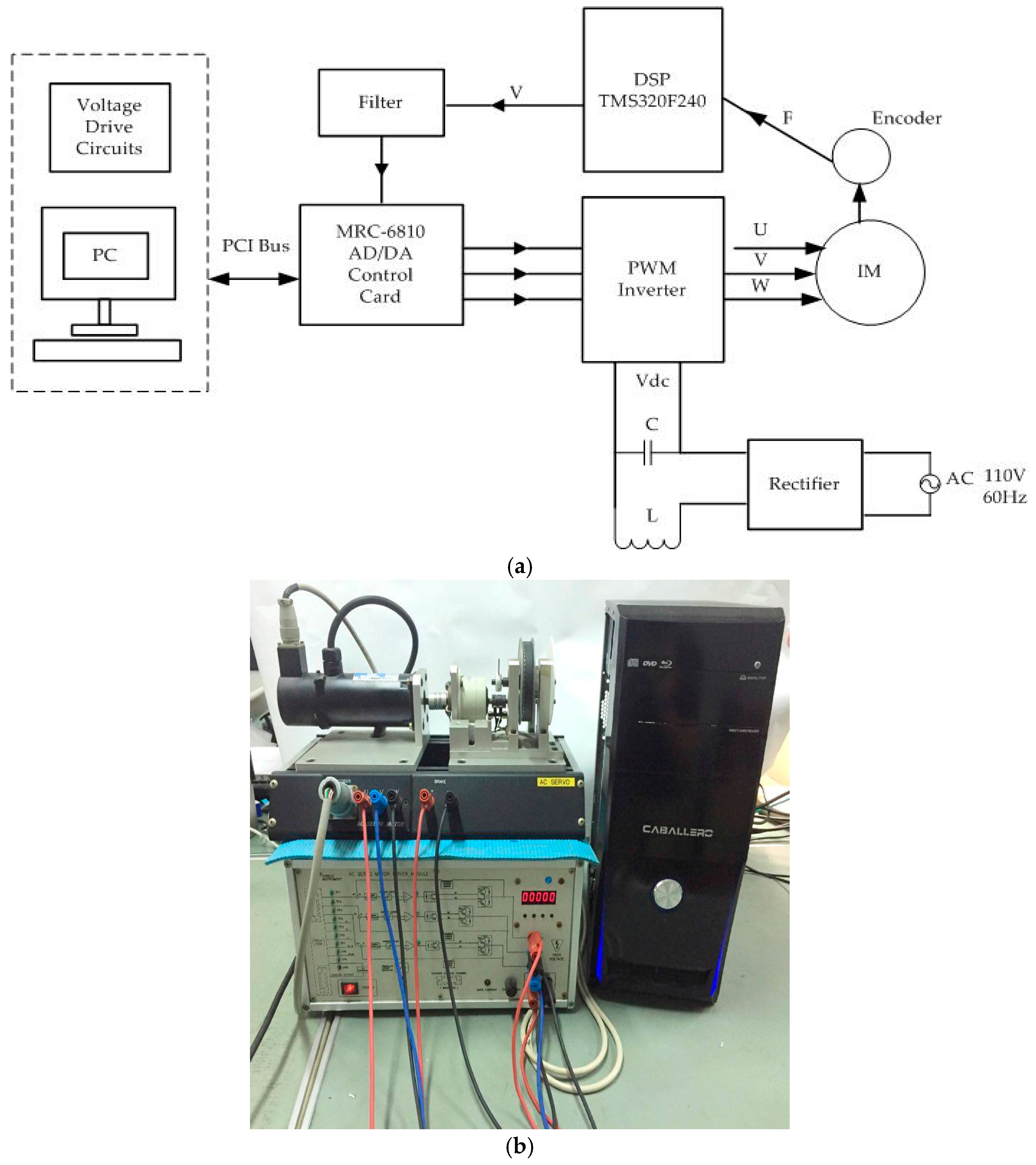
Figure 6 shows the block diagram of the functional implementation structure of the Matlab/Simulink on the PC and the Arduino. The details of those modules and connections can be referred to in
Figure 1 and Equations (1)–(3), (5)–(10) and (14)–(23).
Figure 7 displays the PC-implemented induction motor control system. The real-time implementation of the control system employs the MRC-6810 AD/DA servo control card as the interface between software and hardware. The MRC-6810 card resides in the PC and is directly connected to the block diagram of the multi-channel AD/DA converter of the Matlab/Simulink on the PC to send and receive signals. The voltage drive circuit residing in PC yields adequate voltage signals based on signal outputs from the Matlab/Simulink on the PC to the PWM inverter via the D/A channel of the MRC-6810 card. The motor speed is sensed by the speed encoder mounted on the rotor shaft. The encoder produces a pulse signal, and then the frequency (F) of the pulse signal is converted into a voltage signal (V) by the DSP TMS320F240. The voltage signal is fed back to the Matlab/Simulink on the PC via the A/D channel of the MRC-6810 card to complete the speed feedback action.
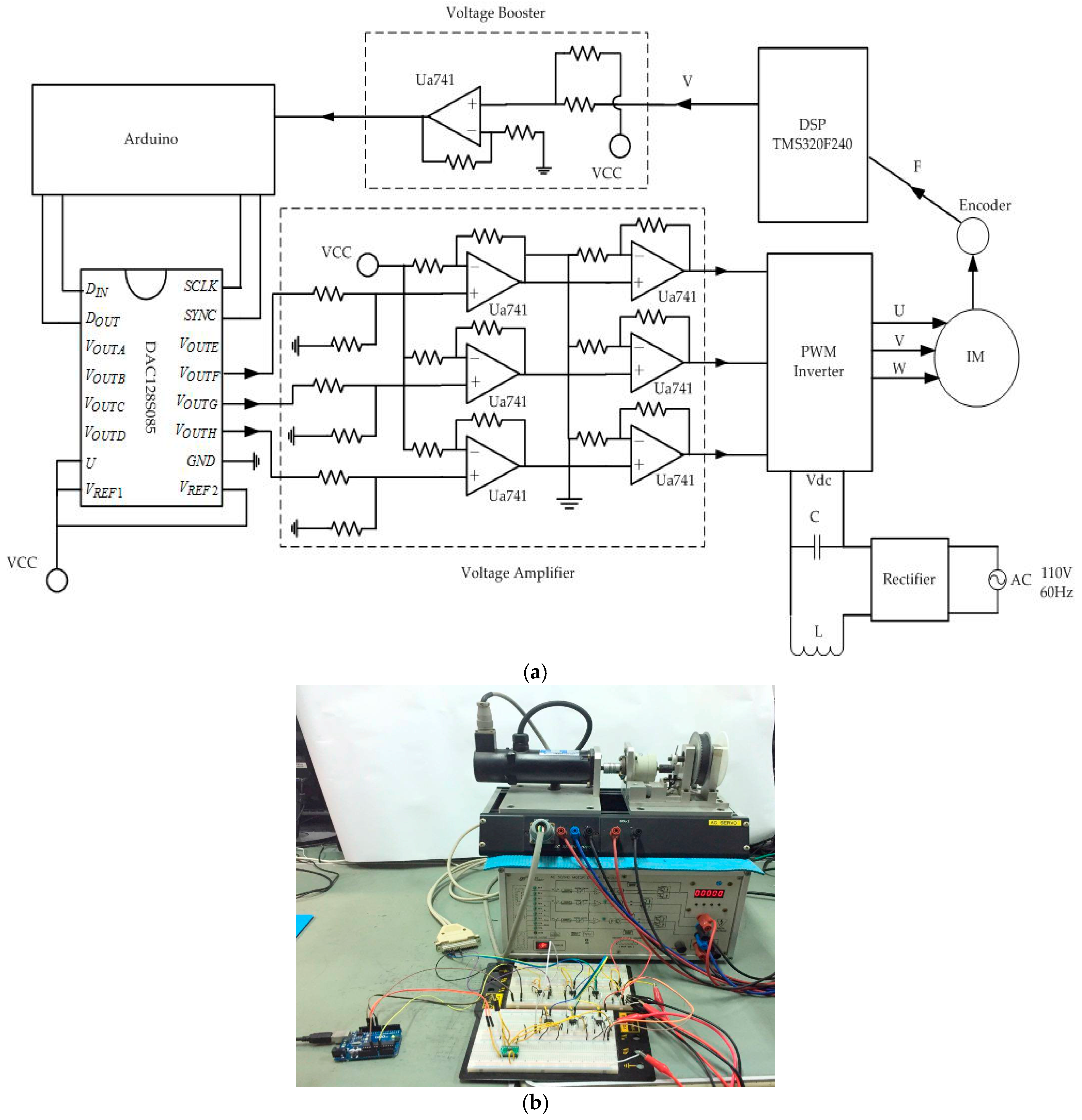
Figure 8 shows the Arduino-implemented induction motor control system. The Arduino model UNO—a single-chip microcomputer—is used. It provides the simplicity of operating its I/O interface, and a user-friendly Java programming development environment. It has the built-in A/D operation but has no D/A function. Furthermore, the operating ranges of its input and output voltages are different from those of the output voltages of the DSP TMS320F240 as well as those of input voltages of the PWM inverter. Thus, we design adequate external circuits to integrate the Arduino into the induction motor control system. First, a voltage booster circuit is designed and utilized for increasing analog feedback voltage signals from the DSP TMS320F240 with a range of ±1.5 V to reach the voltage range of zero to five volts as the Arduino input. Then zero to five volt analog signals are converted to digital signals via the Arduino’s built-in A/D converter. Second, since the Arduino has no built-in D/A converter, the 12-bit DAC128S085 chip is used. Moreover, a voltage amplifier circuit is designed and utilized for increasing analog signal outputs from the D/A converter to the voltage range of −10 V to +10 V as the PWM inverter inputs.
4.2. Experimental Results
In the sequel, the proposed modified Z-N PID+Fuzzy, the modified Z-N PID and the Z-N PID are abbreviated as Modified Z-N+Fuzzy, Modified Z-N and Z-N, respectively.
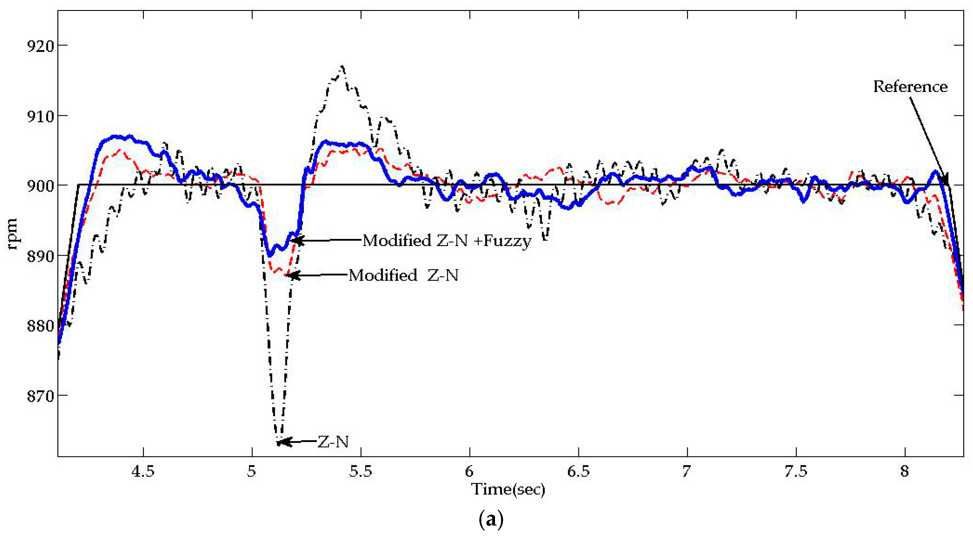
In the experimental tests, we use a cycle of the reference speed command. The reference speed is increased from 0 rpm to 900 rpm at 4.25 s and then starts decreasing from 900 rpm at 8.25 s to −900 rpm at 16.25 s and subsequently, starts increasing from −900 rpm at 20.25 s to 0 rpm at 24.25 s. In addition, test cases with and without sudden load change are as follows:
Case A. No external load torque is applied to the shaft;
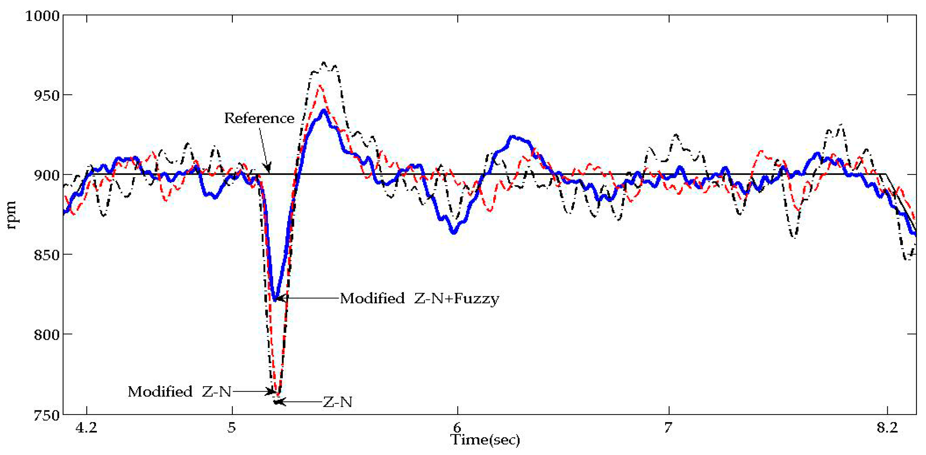
Case B. An external load torque of 1.1 Nm is suddenly applied to the shaft at 5 s;
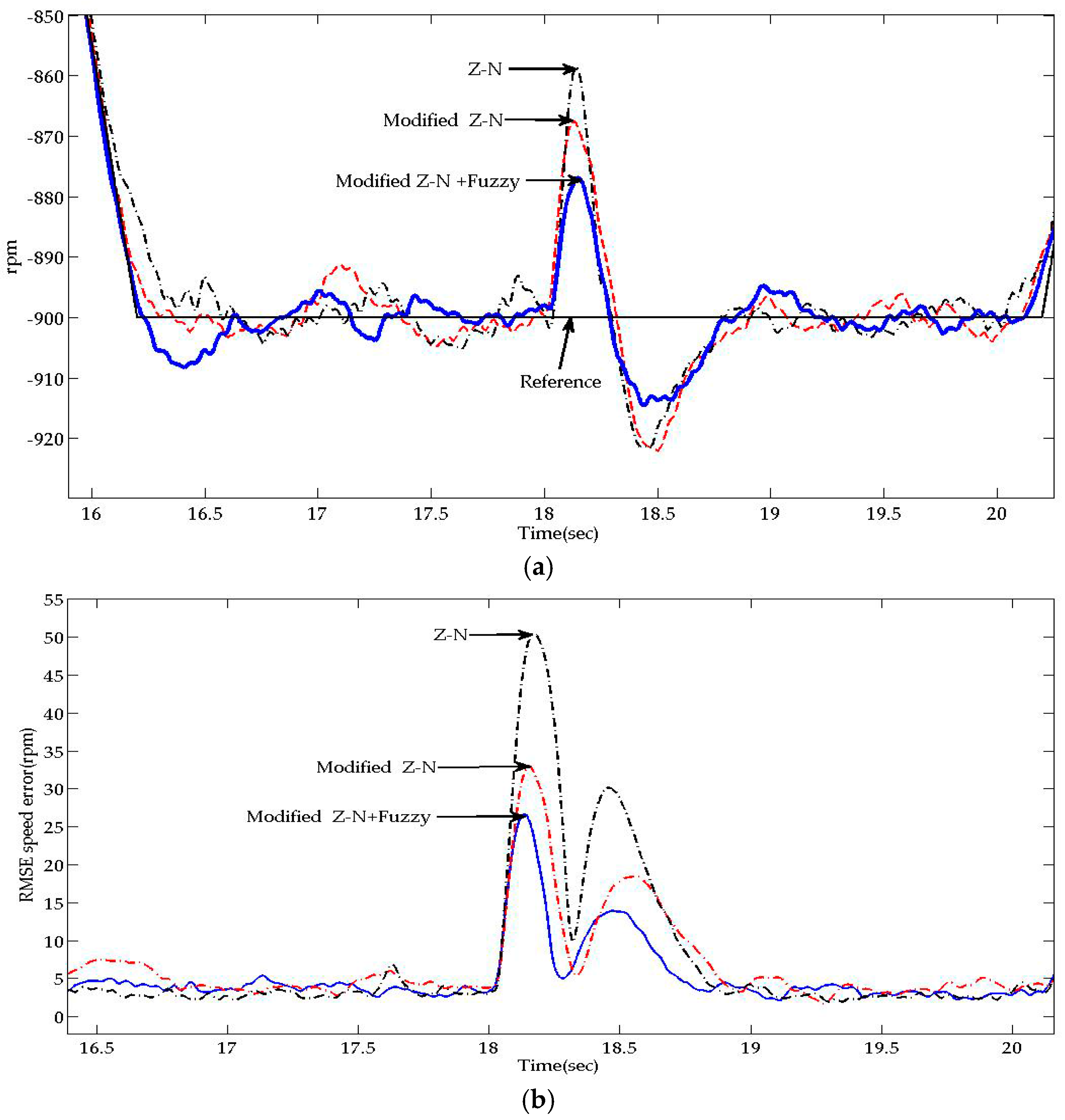
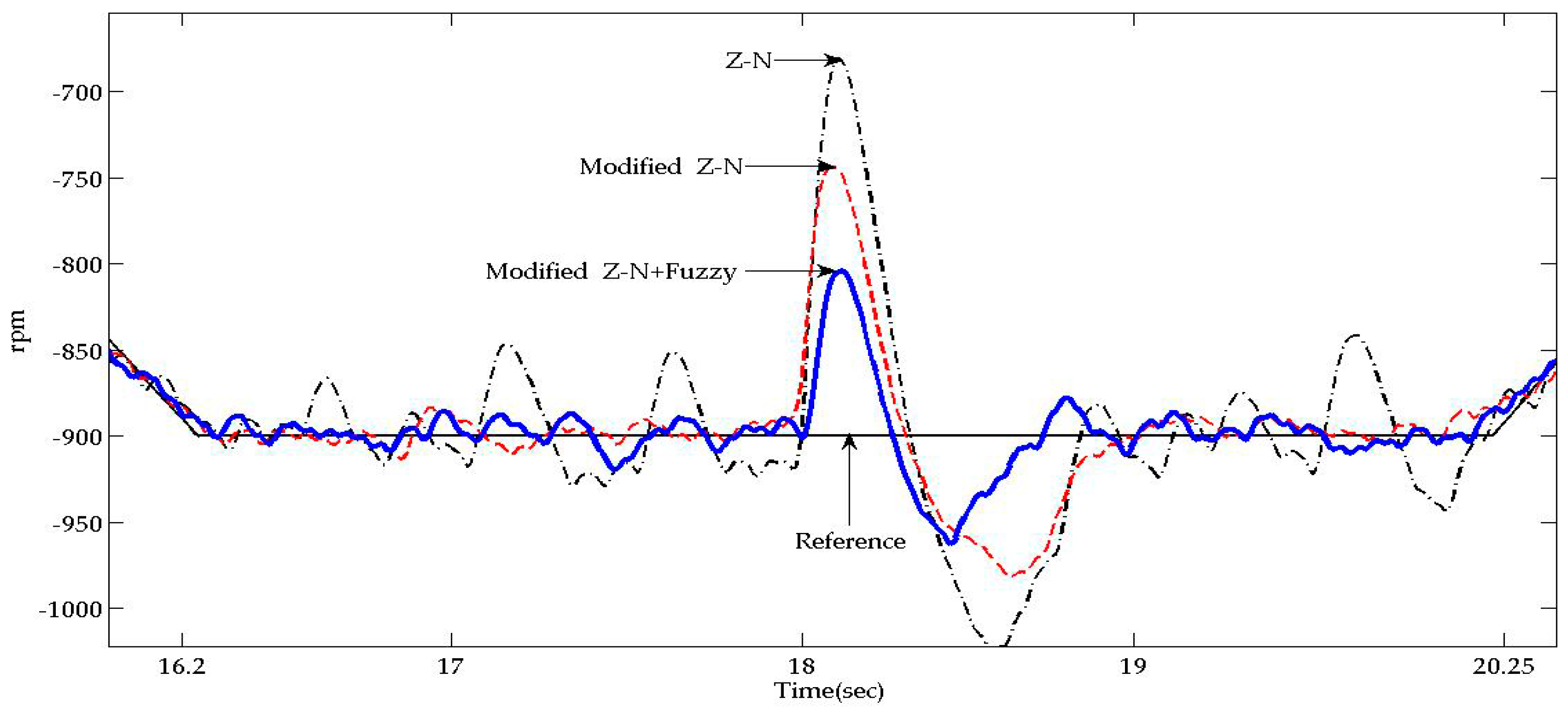
Case C. An external load torque of 1.1 Nm is suddenly applied to the shaft at 18 s.
For the PC-based and the Arduino-based experiments, we obtain the instantaneous velocity tracking performance of the V/f controlled IM using Modified Z-N+Fuzzy, Modified Z-N and Z-N. We also obtain the root-mean-square-errors (RMSE) of each method based on the average over 100 runs for the PC-based experiments. In addition, numerical comparisons of robust tracking performance with and without sudden load changes can be acquired based on maximum speed error (%) between 4.2 s and 8.25 s as well as that between 16.25 s and 20.25 s). The settling time is also taken into account (i.e., when the reference speed 900 rpm/or −900 rpm, after the motor speed reaches 900 rpm/or −900 rpm, the last time that the motor speed lies between 855 rpm and 945 rpm/or −855 rpm). No steady state error is considered since the command speed is time-varying.
The experimental results consistently confirm that the proposed Modified Z-N+Fuzzy is the best among controllers tested. The Arduino-implemented Modified Z-N+Fuzzy for the V/f controlled IM speed tracking generally yields higher tracking errors (e.g., larger maximum speed error) and longer settling time than its PC-based counterpart. Even so, it is a favorable choice when the tradeoff between price, size and robust tracking performance is taken into account.
4.2.1. PC-Based IM Speed Tracking
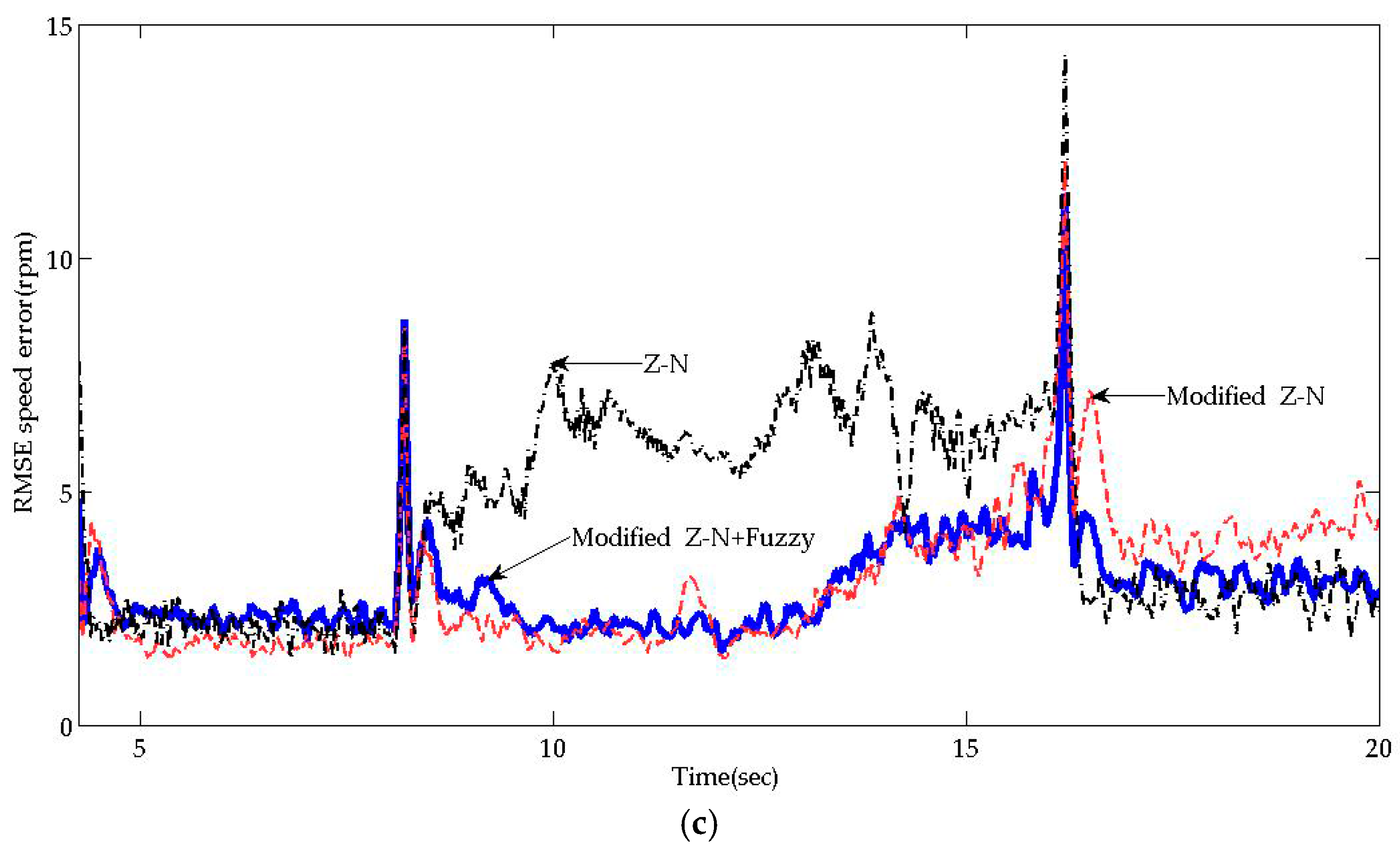
Experimental results for the Case A are shown in
Figure 9 and
Table 1. The instantaneous and the RMSE performance in
Figure 9 show that the proposed Modified Z-N+Fuzzy can track the command speed slightly better than other controllers.
Table 1 shows that the proposed Modified Z-N+Fuzzy slightly outperforms other controllers under no sudden load change in terms of smaller maximum speed error and quicker settling time.
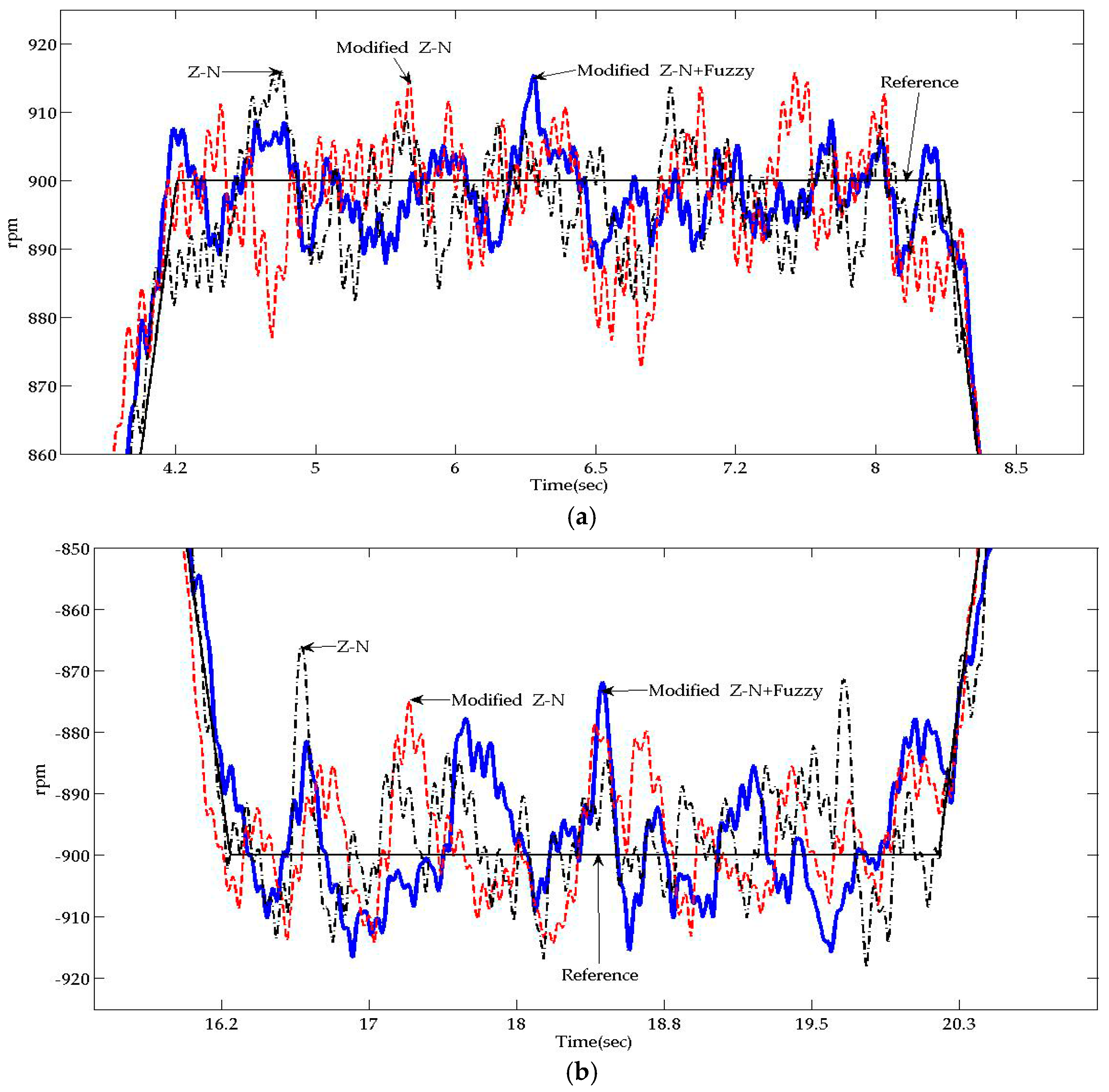
Experimental results for the Case B and those for the Case C are shown in
Figure 10 and
Figure 11, respectively.
Figure 10 and
Figure 11 show that the proposed Modified Z-N+Fuzzy is more robust than the other controllers since it results in both smaller velocity tracking errors and quicker system response reversion to normal when a load torque disturbance suddenly takes place. Moreover,
Table 2 and
Table 3, show that the proposed Modified Z-N+Fuzzy has smaller maximum speed error and shorter settling time under a sudden load change.
4.2.2. Arduino-Based IM Speed Tracking
Unlike a PC, the Arduino is far cheaper but it does not have sufficient memory for storing a large amount of data. As a result, Arduino-based experimental tests can only yield instantaneous performance. No RMSE performance can be acquired.
For the case with no sudden load change, the experimental results are shown in
Figure 12 and
Table 4.
Figure 12 displays that the Modified Z-N+Fuzzy yields slightly smaller velocity tracking errors than other controllers.
Table 4 indicates that the proposed Modified Z-N+Fuzzy achieves slightly smaller maximum speed error and settling time. They are consistent with the conclusion resulting from the PC-based experimental outcomes in
Figure 9 and
Table 1. For the cases with sudden load changes, the experimental outcomes are shown in
Figure 13 and
Figure 14 and
Table 5 and
Table 6. They show that the Modified Z-N+Fuzzy is much more robust than the other controllers because it yields much smaller peak tracking error and faster settling time when a load torque disturbance suddenly takes place. This is consistent with the conclusion drawn from
Figure 10 and
Figure 11 and
Table 2 and
Table 3.


