Seismic Analysis of Steel Solid Web Girder-RC Tubular Column Hybrid Structure

1
School of Civil Engineering, Xi’an University of Science and Technology, Xi’an 710054, China
2
School of Civil Engineering, Chang’an University, Xi’an 710061, China
*
Author to whom correspondence should be addressed.
Appl. Sci. 2018, 8(11), 2095; https://doi.org/10.3390/app8112095
Submission received: 12 September 2018
/
Revised: 17 October 2018
/
Accepted: 24 October 2018
/
Published: 31 October 2018
(This article belongs to the Special Issue Seismic Metamaterials)
Abstract
:This paper aims to investigate the seismic performance of a novel type of steel–concrete hybrid supporting structure consisting of reinforced concrete (RC) tubular columns, steel solid web girder platform, and A-shaped steel frames. It is typically used to house air-cooled condensers (ACC) in thermal power plants (TPPs). First, the finite-element (FE) model was implemented in ABAQUS and the simulation approaches were validated by pseudo-dynamic test results of a scaled steel-concrete hybrid supporting structure. Then, the elasto-plastic time-history analysis of the steel solid web girder-RC tubular column hybrid structure was conducted. The El Centro (NS) record was scaled to peak ground acceleration (PGA) of 0.07, 0.20, 0.40 and 0.62 g to reflect the frequent, basic, rare, and very rare earthquakes. The dynamic characteristics, base shear force, lateral deformation performance, stiffness deterioration, and damage evolution characteristics were analyzed. The numerical results showed that the first vibration mode of this hybrid structure is torsion, due to its small torsional stiffness and the nonuniform distribution characteristics of stiffness and mass in the vertical direction; the lateral deformation shape is shear mode; and the damage mainly occurred on the RC tubular columns, while the steel components did not yield under severe earthquakes. In general, the overall seismic performance of the steel solid web girder-RC tubular column hybrid structural system could meet the seismic design requirements with respect to the high-intensity earthquakes.
1. Introduction
Steel–concrete hybrid structural systems are obtained through the combination of structural components made of steel, reinforced concrete (RC), and composite steel–concrete. They are more efficient and economical compared to either traditional steel or RC structures, since they can make full use of the advantages of different materials [1,2,3,4]. A great deal of research on steel–concrete hybrid structures has been carried out in the past, and many high-rise buildings have applied steel–concrete hybrid structural systems [5,6,7]. Especially for industrial buildings, a steel–concrete hybrid structure is a good structural system to realize flexible structural layouts to meet special industrial and load demands [8,9,10]. Attention in this study is focused on a peculiar steel–concrete hybrid structure typically applied as the supporting structural system to house air-cooled condensers (ACCs) in thermal power plants (TPPs).
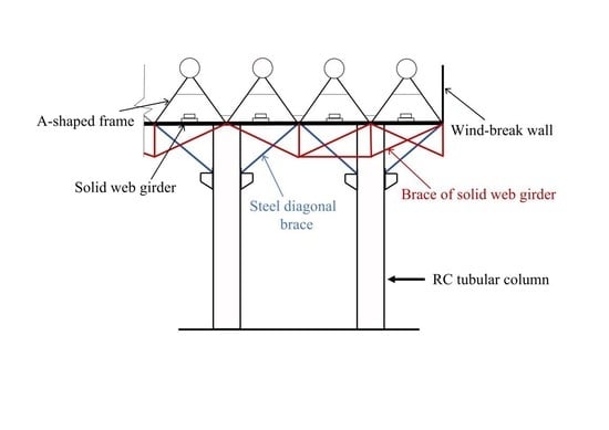
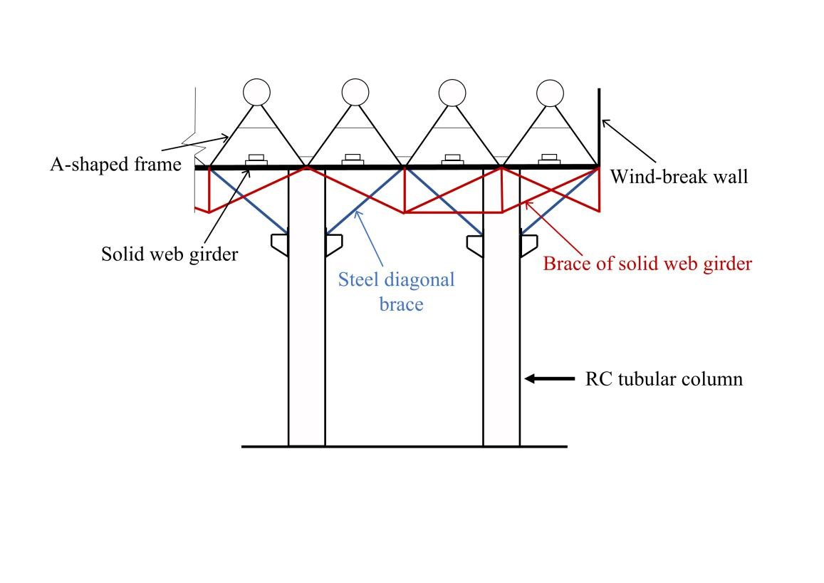
Nowadays, the most popular supporting structural system in TPPs is the steel truss-RC tubular column hybrid structure, which consists of A-shaped steel frames, steel space-truss platform and RC tubular columns [11,12]. However, past research results showed that this kind of structural system is suitable for a medium capacity of TPPs of no greater than 600 MW because of its lower lateral and vertical stiffness [13]. To satisfy the design requirements with the increase of unit capacity of TPPs, several researchers proposed a novel supporting structural system named the steel braced truss-RC tubular column hybrid structure, in which diagonal steel braces were used to connect the steel truss and RC tubular columns to upgrade the structural safety performance [14,15]. However, since there are too many steel elements and connections in this kind of hybrid structure, the constructions are rather complex, and the cost is very high. To solve this problem, some researchers suggested to replace the steel truss by using the steel solid web girder in two orthogonal directions, developing a novel supporting structural system referred to as steel solid web girder-RC tubular column hybrid structure, which has been applied in practice. Figure 1 shows the schematic diagram and a typical photo for this kind of hybrid structure. Similar with the steel braced truss-RC tubular column hybrid structure, steel diagonal braces were used to connect the RC tubular columns and the solid web girder. In addition, steel braces were also set below the solid web girder to improve the overall stiffness of the platform. The statistical analysis showed that the amount of steel used in the steel solid web girder-RC tubular column structure could decrease about 30% compared with the steel braced truss-RC tubular column structure [16]. However, the seismic performance of the steel solid web girder-RC tubular column hybrid structure has not been verified yet.
In this study, the seismic analysis of a steel solid web girder-RC tubular column hybrid structure was conducted. First, numerical modeling approaches were validated by a range of pseudo-dynamic test results. Then, the numerical model of steel solid web girder-RC tubular column hybrid structure was developed to carry out the elasto-plastic time-history analysis. The dynamic characteristics, time-history curves of base shear force and roof lateral displacement, lateral deformation pattern, maximum drift ratios, lateral stiffness deterioration, and damage evolution characteristics were analyzed.
2. Case Study
A typical steel solid web girder-RC tubular column hybrid structure was designed for the case study. The total height was 61.4 m. According to the China seismic design code [17], the seismic precautionary intensity is 8-degree with a peak ground acceleration (PGA) of 0.20 g. This means that when an earthquake with 10% probability of exceedance in 50 years occurs in this region, the seismic intensity is 8 degrees and the corresponding PGA is 0.20 g. The site soil class was II. The structural plan layouts and elevation views are shown in Figure 2. Table 1 lists the strength grades of the materials and cross sections of main components.
All the structures should satisfy the seismic demands under three hazard levels according to the China seismic design code [17]. The three hazard levels mean frequent, basic and rare earthquakes, respectively. The corresponding probabilities of exceedance in 50 years for the three hazard levels are 63.3%, 10% and 2%. All the structures should keep elastic under frequent earthquakes (Level 1), be in use after repair under basic earthquakes (Level 2), and not collapse under rare earthquakes (Level 3). Especially, according to the seismic ground motion parameters zonation map of China [18], the air-cooled condenser supporting structure presented in this paper should also not collapse under very rare earthquakes with 10−4 probability of exceedance in one year (Level 4) except for the three hazard levels introduced above, since it belongs to lifeline engineering, which should have much higher reliability compared to ordinary buildings.
3. Numerical Approaches and Validation
3.1. Simulation of RC Tubular Columns
A general shell element with four nodes S4R was adopted to simulate the tubular column. It was a quadrilateral shell element with reduced integration. Transverse shear deformation was considered. For each cross-sectional point along the thickness direction of the shell element, the numerical integration method was adopted to calculate the stress and strain. To simulate the progressive failure process of the shell element, five integration points were assigned in the thickness direction [19,20,21,22].
The concrete damaged plasticity (CDP) model was adopted to simulate the mechanical behavior of concrete [23]. According to the China design code of concrete structures [24], the parameters of the CDP model can be determined using Equations (1)–(7).
where dt and dc are respectively the uniaxial tensile and compressive damage evolution parameters for concrete; E0 is the initial elastic modulus of concrete; εt0 and εc0 are, respectively, the peak strains of the uniaxial tensile and compressive stress-strain curves for concrete; αt and αc are, respectively, the descending stage parameters of the uniaxial tensile and compressive stress–strain curves for concrete, equal to 1.95 and 1.94, respectively; fc is the uniaxial compressive strength of concrete.
Equations (8) and (9), respectively, give the expression of elastic complementary energy for the undamaged and damaged materials.
where σ and are, respectively, the Cauchy stress and effective stress; D is the scalar damage variable.
It is supposed that there is no damage before the stresses reach the peak values. Correspondingly, Equations (12) and (13) can be used to illustrate the CDP model, as shown in Figure 3.
3.2. Simulation of Steel Components
A three-dimensional beam element B31 with two nodes was adopted to simulate the steel components, i.e., the solid web girder, braces, and A-shaped frames. The bilinear kinematic hardening model was employed to model the stress-strain relationship of steel. Four types of cross sections including box-, I-, circular-, and L-shaped were used for the steel components, and the number of integration points are, respectively, 16, 13, 8, and 9.
3.3. Validation of the Modelling Approaches
In the past, the authors conducted pseudo-dynamic tests (PDTs) on a 1/8 scaled substructure to investigate the seismic behavior of steel braced truss-RC tubular column hybrid structure [14]. The scaled El Centro (NS) records with PGA of 0.05, 0.10, 0.20, 0.30, 0.40, 0.60, and 0.80 g were used to simulate different hazard levels. The case of the test is very suitable to the objectives of this study, since the test specimen was also a steel–concrete hybrid supporting structure. Accordingly, the experimental results were adopted to validate the accuracy of the numerical simulation approaches as introduced above. Figure 4a shows the test specimen. The FE model of the specimen was established based on the proposed simulation approaches, as shown in Figure 4b. Figure 5 shows the comparison of time-history curves for lateral displacements and maximum lateral displacements versus height curves between the FE simulation and test results. It can be observed that the numerical and test results exhibited a good agreement, indicating that the proposed FE modelling approaches could reasonably simulate the seismic behavior of this kind of steel–concrete hybrid structure.
3.4. Numerical Model of the Steel Solid Web Girder-RC Tubular Column Hybrid Structure
Based on the modeling approaches which have been validated above, the FE model of the steel solid web girder-RC tubular column hybrid structure was developed, as shown in Figure 6.
4. Numerical Results and Discussion
4.1. Dynamic Characteristics
Table 2 provides the numerical results of natural periods, mode shapes, and participating mass coefficients for the first three vibration modes. As shown in Figure 7a, the first vibration mode of the steel solid web girder-RC tubular column hybrid structure was torsion due to its small torsional stiffness. This is caused by the uniform distribution of stiffness and mass which mainly distribute on the superstructure. Both second and third vibration modes were translations, as shown in Figure 7b,c. Since the torsion is averse to the seismic resistance, the China seismic design code recommended that the first torsion to first translation period ratio should not be greater than 0.85 [17]. For the steel solid web girder-RC tubular column hybrid structure, the calculated period ratio was about 1.03 greater than 0.85, indicating that the torsional effect of this hybrid structure should be considered in the structural design.
4.2. Nonlinear Dynamic Time-History Analysis
The El Centro (NS) record was selected as the input ground motion because of its ample spectral components and adaptability to the sites. As introduced in Section 2, the steel solid web grider-RC tubular column hybrid structure should satisfy the seismic demands under four hazard levels. Since the seismic precautionary intensity is 8-degree, the PGA of input ground motion was respectively scaled to 0.07, 0.20, 0.40, and 0.62 g to reflect the frequent, basic, rare, and very rare earthquakes according to the China seismic design code [17] and the seismic ground motion parameters zonation map of China [18].
Table 3 provides the numerical results of maximum base shear forces and shear-weight ratios. The shear-weight ratio of the structure was defined as the maximum base shear force to the representative value of gravity load ratio. According to the China technical specification for concrete structures of tall buildings [26], the floor shear-weight ratio of the structure with significant torsion effect or whose fundamental period is less than 3.5 s under the frequent earthquake should be no less than 0.032. The numerical results showed that the shear-weight ratio of the solid web girder-RC tubular column hybrid structure under the frequent earthquake was 0.059 greater than 0.032, indicating that it could meet the design requirements.
Figure 8 shows the time-history curves of base shear force and roof lateral displacement for the solid web girder-RC tubular column hybrid structure under different hazard levels. It can be observed that the occurring moment of peak responses were delayed with increase of PGA. This is because the structural damage gradually generated and accumulated with increase of PGA, resulting in the deterioration of lateral stiffness.
4.3. Lateral Deformation Performance
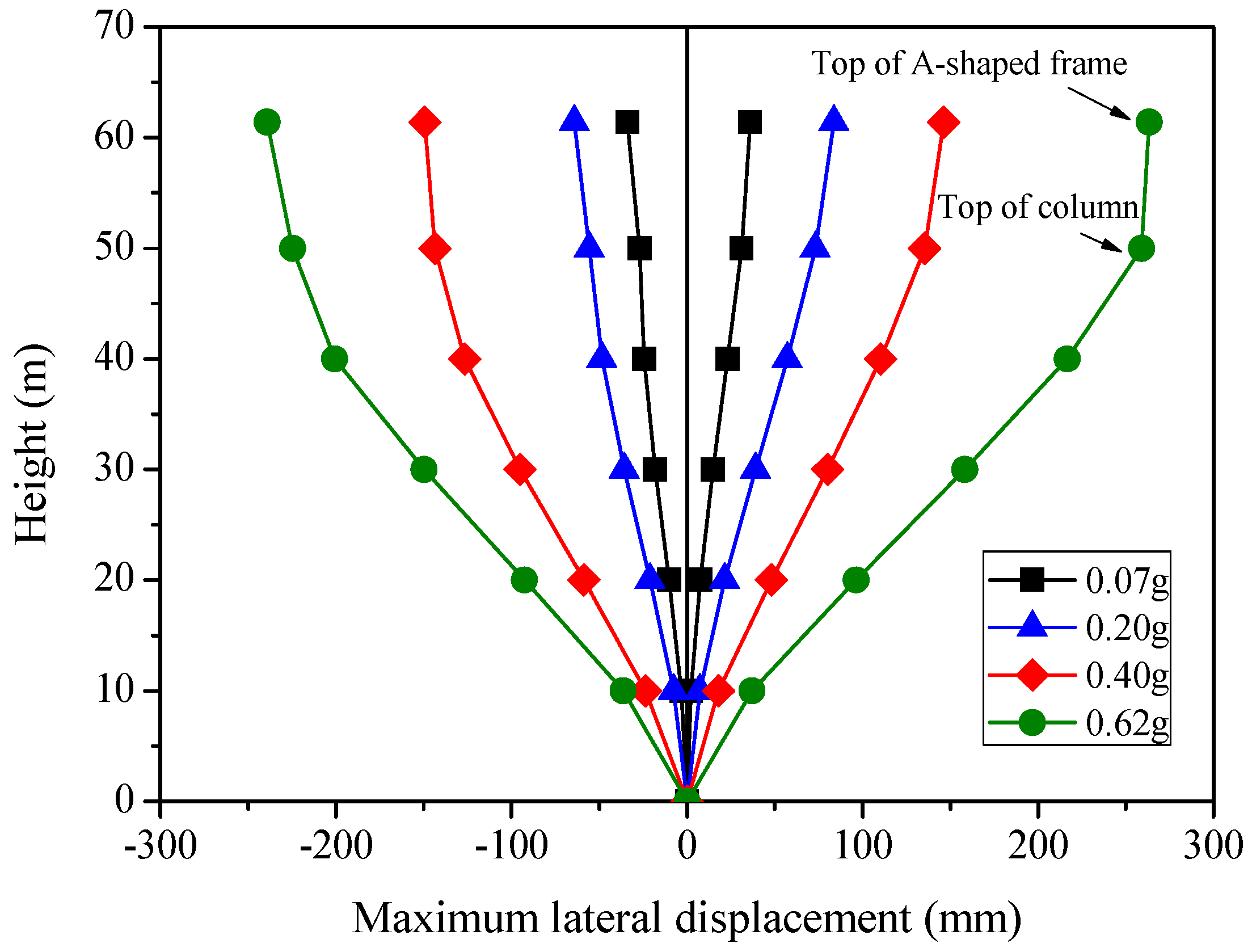
Table 4 summarizes the numerical results of maximum lateral displacements and drift ratios. According to the China technical code for the design of civil structure of fossil-fired power plant [27], the maximum drift ratio on the top of column for the air-condenser supporting structure should not be larger than 0.2% under normal service stages. The numerical results showed that the maximum drift ratios on the top of column under the frequent and basic earthquakes were respectively 0.06 and 0.15 less than the upper limit value, indicating that the solid web girder-RC tubular column hybrid structure could meet the design requirements of the seismic resistant structures; that is, the structure should keep elastic under the frequent earthquake and be in use after repairment under the basic earthquake.
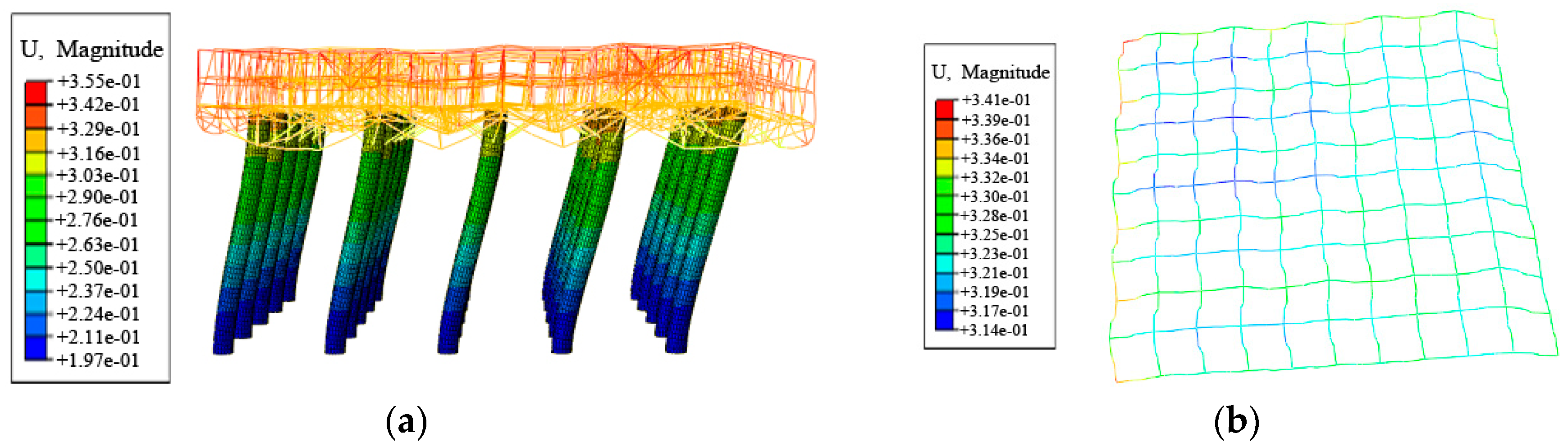
Figure 9 shows the maximum lateral displacement versus height curves under different hazard levels. Figure 10a,b shows the lateral deformation nephograms of the whole structure and steel solid web girder platform under the rare earthquake. It can be observed that the lateral deformation pattern of the steel solid web girder-RC tubular column hybrid structure was shear mode. Since the stiffness of the superstructure is much larger than that of the substructure, the in-plane deformation of the steel solid web girder was very small, as shown in Figure 10b.
4.4. Lateral Stiffness Deterioration and Damage Analysis
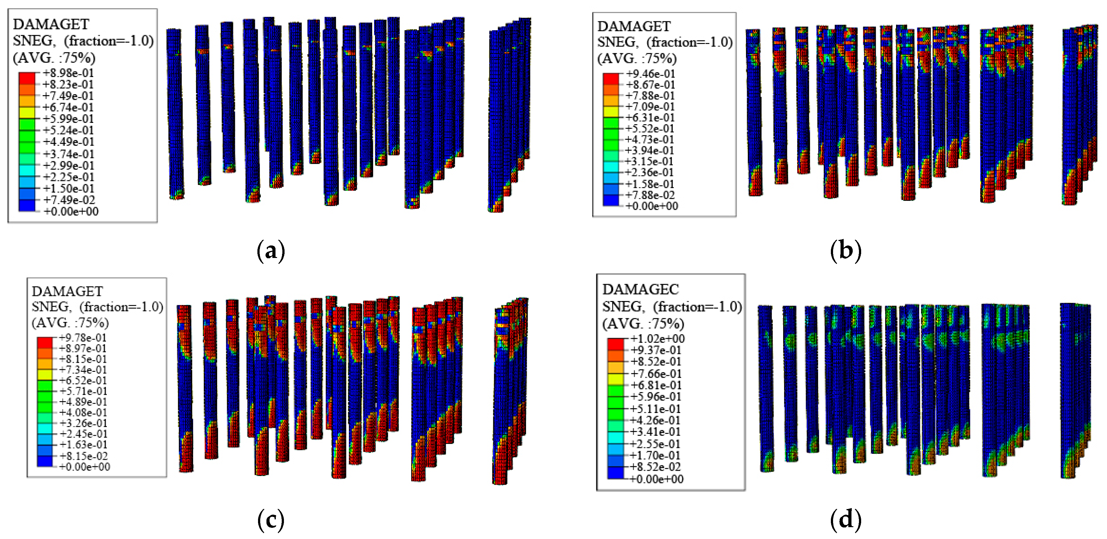
Table 5 summarizes the numerical results of maximum stresses of A-shaped steel frames, steel braces and steel solid web girder under different hazard levels, as shown in Figure 11. It can be observed that the steel components of steel solid web girder-RC tubular column hybrid structure did not yield under the earthquakes. Figure 12 shows the damage distribution patterns of the RC tubular columns under different hazard levels. It can be seen that the damage mainly occurred on the bottom of the RC tubular column, lower part of the corbel, and upper part of the corbel. This phenomenon is similar with the experimental result of the steel braced truss-RC tubular column hybrid structure and the failure mechanism has been clarified through mechanical analysis [14]. Generally, in the seismic design, the failure hierarchy criterion strong column-weak beam is applied. The aim of the proposed procedure is the earlier development of yielding in beams rather in columns [28,29,30]. However, for the structure described in this paper, the damage mainly occurred on the columns while the steel components did not yield. In fact, this coincided with the expected design results. Since the steel solid web girder platform and A-shaped frames must bear the important industrial units directly in practical engineering, if the steel components yield untimely, the normal use of the industrial units would be affected. Accordingly, they are expected to suffer negligible damage under earthquakes. In addition, as the key components to improve the overall stiffness and structural integrity, the steel diagonal braces should be designed strong enough.
Figure 13 shows the changing rules of relative stiffness ratios and maximum damage indexes with increase of the PGA. It can be found that the lateral stiffness of solid web girder-RC tubular column hybrid structure under the very rare earthquake was still 39% of the initial stiffness, although the stiffness deteriorated significantly with increase of the PGA. In addition, it can be observed that the maximum tensile damage index was 0.90 under the very rare earthquake (PGA = 0.62 g), indicating that the structure was severely damaged but did not collapse. Overall, the numerical results showed that the steel solid web girder-RC tubular column hybrid structure could satisfy the seismic design requirements under the four hazard levels.
5. Conclusions
The steel solid web girder-RC tubular column hybrid structure is a novel supporting structural system typically used to house air-cooled condensers in TPPs. This paper investigates the seismic performance of this hybrid structure through finite element analysis. The El Centro (NS) record was scaled to peak ground acceleration (PGA) of 0.07, 0.20, 0.40, and 0.62 g to reflect the frequent, basic, rare, and very rare earthquakes. The main conclusions are summarized as follows:
- (1)
- This paper proposes the modelling approaches for this kind of supporting structural system. The comparison between the FE numerical results and test results of a model structure indicated that the proposed FE modeling approaches are reasonable to simulate the seismic behavior of this kind of steel-concrete hybrid structure.
- (2)
- Due to the small torsional stiffness and the nonuniform distribution characteristics of stiffness and mass in vertical direction, the first vibration mode of steel solid web girder-RC tubular column hybrid structure was torsion. The calculation results of the first torsion to translation period ratio of this hybrid structure showed that it was greater than the upper limit value recommended by the China seismic design code. This indicated that the torsion effect can not be ignored in the design for this kind of hybrid structure. In addition, the shear-weight ratio of this hybrid structure under the frequent earthquake was 0.059, which was greater than the lower limit value recommended by the China technical specification for concrete structures of tall building.
- (3)
- The numerical results of lateral deformation performance showed that it was shear mode for this hybrid structure. The maximum drift ratios on the top of column under the frequent and basic earthquakes were 0.06 and 0.15, respectively. They were less than the upper limit value recommended by the China technical code for the design of civil structure of fossil-fired power plant. In addition, the numerical results showed that the damage mainly occurred on the RC tubular columns, while the steel components of this hybrid structure did not yield under the earthquakes. This coincided with the expected design results considering the normal use of the industrial units directly supported by the steel solid web girder platform and A-shaped frames. Moreover, under the very rare earthquake, the residual lateral stiffness ratio and the maximum tensile damage index of this hybrid structure was 39% and 0.90. This indicated that the structure was severely damaged but did not collapse. Overall, the numerical investigations showed that the seismic performance of steel solid web girder-RC tubular column hybrid structure could satisfy the design requirements in the strong earthquake region.
Author Contributions
H.D. modeled the structure and wrote the paper; B.W. designed the study.
Funding
This research was funded as follows: the National Natural Science Foundation of China (NSFC, Grant No. 51708037), Natural Science Foundation of Shaanxi Province of China (Grant No. 2018JQ5078), China Postdoctoral Science Foundation (Grant No. 2017M610616), Shaanxi Province Postdoctoral Science Foundation (Grant No. 2017BSHEDZZ111), Xi’an Municipal Science and Technology Planning Project (Grant No. 201805045YD23CG29(6)) and the Fundamental Research Funds for the Central Universities (Grant No. 300102288111).
Acknowledgments
Special thanks to Guoliang Bai from Xi’an University of Architecture and Technology for helpful and valuable discussions on the research program.
Conflicts of Interest
The authors declare no conflict of interest.
References
- Dall’Asta, A.; Leoni, G.; Morelli, F.; Salvatore, W.; Zona, A. An innovative seismic-resistant steel frame with reinforced concrete infill walls. Eng. Struct. 2017, 141, 144–158. [Google Scholar] [CrossRef]
- Dall’Asta, A.; Leoni, G.; Zona, A.; Hoffmeister, B.; Bigelow, H.; Degée, H.; Braham, C.; Bogdan, T.; Salvatore, W.; Morelli, F.; et al. Innovative Hybrid and Composite Steel-Concrete Structural Solutions for Building in Seismic Area; Final Report EUR 26932 EN; European Commission: Brussels, Belgium, 2015. [Google Scholar]
- Hajjar, J.F. Composite steel and concrete structural systems for seismic engineering. J. Constr. Steel Res. 2002, 58, 703–723. [Google Scholar] [CrossRef]
- Deierlein, G.G.; Noguchi, H. Overview of US-Japan research on the seismic design of composite reinforced concrete and steel moment frame structures. J. Struct. Eng. 2004, 130, 361–367. [Google Scholar] [CrossRef]
- Sivandi-Pour, A.; Gerami, M.; Kheyroddin, A. Uniform damping ratio for non-classically damped hybrid steel concrete structures. Int. J. Civ. Eng. 2016, 14, 1–11. [Google Scholar] [CrossRef]
- Nguyen, Q.H.; Tran, V.T.; Hjiaj, M. Hybrid RC-steel members under bending and shear: Experimental investigation and design model. J. Constr. Steel Res. 2017, 138, 837–850. [Google Scholar] [CrossRef]
- Keo, P.; Lepourry, C.; Somja, H.; Palas, F. Behavior of a new shear connector for U-shaped steel-concrete hybrid beams. J. Constr. Steel Res. 2018, 145, 153–166. [Google Scholar] [CrossRef]
- Bai, Y.T.; Bai, G.L. Pseudo-dynamic and quasi-static testing of an irregular steel concrete composite frame with wing walls. Int. J. Struct. Stab. Dyn. 2016, 16, 1450095. [Google Scholar] [CrossRef]
- Wang, B.; Bai, G.L.; Dai, H.J.; Zhu, J.N.; Li, H.X. Research on mechanical properties of abnormal SRC joints with short-limb shear walls. Eng. Mech. 2014, 31, 68–75. (In Chinese) [Google Scholar]
- Wang, B.; Bai, G.L.; Liu, L.; Dai, H.J. Elastic-plastic seismic response and anti-seismic lines of SRC frame-bent hybrid structure. J. Vib. Shock 2014, 33, 46–52. (In Chinese) [Google Scholar]
- Bai, G.L.; Zhu, L.H.; Zhao, C.L.; Li, H.X. Model test on behavior of direct air cooled condenser support plat form under service load and earthquake action. J. Build. Struct. 2008, 10, 42–49. (In Chinese) [Google Scholar]
- Yao, Z.L.; Bai, G.L.; Dang, F.N.; Li, H.X. Study on seismic behavior of a steel truss-reinforced concrete column structure. J. Build. Struct. 2011, 32, 30–36. (In Chinese) [Google Scholar]
- Dai, H.J. Study on Seismic Performance Experiment and Methods of the Steel Space Truss-Umbrella Brace Air-Cooled Condenser Structure System. Ph.D. Thesis, Xi’an University of Architecture and Technology, Xi’an, China, 2013. (In Chinese). [Google Scholar]
- Wang, B.; Dai, H.J.; Wu, T.; Bai, G.L.; Bai, Y.T. Experimental investigation on seismic behavior of steel truss-RC column hybrid structure with steel diagonal braces. Appl. Sci. 2018, 8, 131. [Google Scholar] [CrossRef]
- Wang, B.; Wu, T.; Dai, H.J.; Bai, G.L. Numerical Study on the Seismic Performance of a Steel–Concrete Hybrid Supporting Structure in Thermal Power Plants. Appl. Sci. 2018, 8, 294. [Google Scholar] [CrossRef]
- Liu, L. Optimization and Selection of Large-Capacity Unit for Air-Cooling Island Structure; Research Report; Jiangsu Shuangliang Eco-Energy Group: Wuxi, China, 2012. (In Chinese) [Google Scholar]
- Ministry of Housing and Urban-Rural Development of the People’s Republic of China. Code for Seismic Design of Buildings (GB 50011-2010); China Architecture and Building Press: Beijing, China, 2016. (In Chinese)
- General Administration of Quality Supervision. Inspection and Quarantine of the People’s Republic of China; Standardization Administration of the People’s Republic of China; Seismic Ground Motion Parameters Zonation Map of China (GB 18306-2015); China Zhijian Publishing House; China Standards Press: Beijing, China, 2015. (In Chinese)
- Nascimbene, R. Numerical model of a reinforced concrete building: Earthquake analysis and experimental validation. Period. Polytech. Civ. Eng. 2015, 59, 521–530. [Google Scholar] [CrossRef]
- Nascimbene, R. Towards non-standard numerical modeling of thin-shell structures: Geometrically linear formulation. Int. J. Comput. Methods Eng. Sci. Mech. 2014, 15, 126–141. [Google Scholar] [CrossRef]
- Brunesi, E.; Nascimbene, R. Extreme response of reinforced concrete buildings through fiber force-based finite element analysis. Eng. Struct. 2014, 69, 206–215. [Google Scholar] [CrossRef]
- Nascimbene, R. An arbitrary cross section, locking free shear-flexible curved beam finite element. Int. J. Comput. Methods Eng. Sci. Mech. 2013, 14, 90–103. [Google Scholar] [CrossRef]
- Abaqus Documentation and User Manua, version 6.10; Dassault Systemes: Vélizy-Villacoublay, France, 2010.
- Ministry of Housing and Urban-Rural Development of the People’s Republic of China. Code for Design of Concrete Structures (GB50010-2010); China Architecture and Building Press: Beijing, China, 2011. (In Chinese)
- Sidoroff, F. Description of Anisotropic Damage Application to Elasticity; IUTAM Colloquium on Physical Nonlinearities in Structural Analysis; Springer: Berlin, Germany, 1981; pp. 237–244. [Google Scholar]
- Ministry of Housing and Urban-Rural Development of the People’s Republic of China. Technical Specification for Concrete Structures of Tall Building (IGJ3-2010); China Architecture and Building Press: Beijing, China, 2010. (In Chinese)
- National Energy Administration of the People’s Republic of China. Technical Code for the Design of Civil Structure of Fossil-Fired Power Plant (DL 5022-2012); China Plan Press: Beijing, China, 2012. (In Chinese)
- Longo, A.; Montuori, R.; Piluso, V. Moment frames—Concentrically braced frames dual systems: Analysis of different design criteria. Struct. Infrastruct. Eng. 2016, 12, 122–141. [Google Scholar] [CrossRef]
- Montuori, R.; Muscati, R. Smart and simple design of seismic resistant reinforced concrete frame. Compos. Part B 2017, 115, 360–368. [Google Scholar] [CrossRef]
- Montuori, R.; Sagarese, V. The use of steel rbs to increase ductility of wooden beams. Eng. Struct. 2018, 169, 154–161. [Google Scholar] [CrossRef]
Figure 1.
Solid web girder-RC tubular column hybrid structure: (a) Schematic diagram; (b) A typical photo of practical engineering.
Figure 1.
Solid web girder-RC tubular column hybrid structure: (a) Schematic diagram; (b) A typical photo of practical engineering.

Figure 2.
Structural layouts (unit: mm): (a) Plan layouts of RC tubular columns; (b) elevation view along the A-shaped frame direction; (c) elevation view perpendicular to A-shaped frame direction.
Figure 2.
Structural layouts (unit: mm): (a) Plan layouts of RC tubular columns; (b) elevation view along the A-shaped frame direction; (c) elevation view perpendicular to A-shaped frame direction.

Figure 3.
The damage evolution rules of stress-strain laws in the CDP (concrete damaged plasticity) model.
Figure 3.
The damage evolution rules of stress-strain laws in the CDP (concrete damaged plasticity) model.

Figure 4.
Test specimen and numerical model: (a) Test specimen; (b) numerical model.

Figure 5.
Comparison of numerical and test lateral displacements: (a) Top of A-shaped frame under 0.20 g; (b) top of A-shaped frame under 0.40 g; (c) top of A-shaped frame under 0.60 g; (d) maximum lateral displacements.
Figure 5.
Comparison of numerical and test lateral displacements: (a) Top of A-shaped frame under 0.20 g; (b) top of A-shaped frame under 0.40 g; (c) top of A-shaped frame under 0.60 g; (d) maximum lateral displacements.

Figure 6.
FE (Finite element) model of the steel solid web girder-RC tubular column hybrid structure: (a) Whole model; (b) part of the model.
Figure 6.
FE (Finite element) model of the steel solid web girder-RC tubular column hybrid structure: (a) Whole model; (b) part of the model.

Figure 7.
Vibration mode shapes: (a) First mode; (b) second mode; (c) third mode.

Figure 8.
Time-history curves of base shear force and roof lateral displacement under different hazard levels: (a) Base shear force; (b) roof lateral displacement.
Figure 8.
Time-history curves of base shear force and roof lateral displacement under different hazard levels: (a) Base shear force; (b) roof lateral displacement.

Figure 9.
Maximum lateral displacement versus height curves under different hazard levels.

Figure 10.
Lateral deformation nephograms of the structure under the rare earthquake (PGA (Peak ground acceleration) = 0.40 g): (a) Whole structure; (b) steel solid web girder platform.
Figure 10.
Lateral deformation nephograms of the structure under the rare earthquake (PGA (Peak ground acceleration) = 0.40 g): (a) Whole structure; (b) steel solid web girder platform.

Figure 11.
Maximum stresses of the steel components under different hazard levels.

Figure 12.
Damage distribution of RC tubular columns subjected to different hazard levels: (a) Tensile damage under basic earthquakes; (b) tensile damage under rare earthquakes; (c) tensile damage under very rare earthquakes; (d) compressive damage under very rare earthquakes.
Figure 12.
Damage distribution of RC tubular columns subjected to different hazard levels: (a) Tensile damage under basic earthquakes; (b) tensile damage under rare earthquakes; (c) tensile damage under very rare earthquakes; (d) compressive damage under very rare earthquakes.

Figure 13.
Relative stiffness ratios and maximum damage indexes under different hazard levels.


Table 1.
Strength grades of materials and cross sections of the main components.
| Component | Material | Strength Grade | Location | Cross Section (mm) | |
|---|---|---|---|---|---|
| Tubular column | Concrete | C40 | External diameter | 4000 | |
| Wall thickness | 400 | ||||
| Steel rebar | HRB400 | Longitudinal rebar | Φ25 | ||
| HPB300 | Circular stirrup | Φ10 | |||
| Steel solid web girder platform | Steel | Q345 | Solid web girder | Main direction | H1300 × 450 × 16 × 22 |
| Secondary direction | H1300 × 450 × 16 × 22 | ||||
| Brace of solid web girder | TUB250 × 250 × 12 | ||||
| Steel diagonal brace | Diagonal brace | TUB450 × 450 × 20 | |||
| A-shaped frame | Horizontal beam | HM390 × 300 | |||
| Diagonal column | HW250 × 250 | ||||
Table 2.
Numerical results of dynamic characteristic parameters.
| Mode | Natural Period (s) | Mode Shapes | Participating Mass Coefficient | ||
|---|---|---|---|---|---|
| X Direction | Y Direction | RZ Direction | |||
| 1 | 1.291 | Torsion | 0.001 | 0.000 | 0.976 |
| 2 | 1.251 | Y-direction translation | 0.987 | 0.000 | 0.001 |
| 3 | 1.239 | X-direction translation | 0.000 (0.988) | 0.986 (0.986) | 0.977 (0.977) |
Note: The value in the bracket means the accumulated participating mass coefficient for the first three modes.
Table 3.
Maximum base shear forces and shear-weight ratios.
| Hazard Level (PGA) | Frequent Earthquake (0.07 g) | Basic Earthquake (0.20 g) | Rare Earthquake (0.40 g) | Very Rare Earthquake (0.62 g) | ||||
|---|---|---|---|---|---|---|---|---|
| Positive (+) | Negative (−) | Positive (+) | Negative (−) | Positive (+) | Negative (−) | Positive (+) | Negative (−) | |
| Maximum base shear force (kN) | 18,361 | 15,741 | 29,612 | 32,927 | 43,055 | 41,666 | 60,826 | 61,718 |
| Shear-weight ratio | 0.059 | 0.050 | 0.094 | 0.105 | 0.137 | 0.133 | 0.194 | 0.197 |
Table 4.
Summary of maximum lateral displacements and drift ratios.
| Hazard Level (PGA) | Maximum Lateral Displacement (mm) | Maximum Drift Ratio (%) | ||
|---|---|---|---|---|
| Top of A-Shaped Frame | Top of Column | Top of A-Shaped Frame | Top of Column | |
| Frequent earthquake (0.07 g) | 36.04 | 31.16 | 0.06 | 0.06 |
| Basic earthquake (0.20 g) | 83.71 | 73.26 | 0.14 | 0.15 |
| Rare earthquake (0.40 g) | 149.25 | 143.65 | 0.24 | 0.29 |
| Very rare earthquake (0.62 g) | 263.45 | 259.02 | 0.43 | 0.52 |
Table 5.
Maximum stresses of steel components under different hazard levels (MPa).
| Hazard Level (PGA) | A-Shaped Frame | Solid Web Girder | Brace of Solid Web Girder | Steel Diagonal Brace |
|---|---|---|---|---|
| Frequent earthquake (0.07 g) | 72 | 98 | 88 | 115 |
| Basic earthquake (0.20 g) | 112 | 156 | 117 | 173 |
| Rare earthquake (0.40 g) | 167 | 211 | 144 | 243 |
| Very rare earthquake (0.62 g) | 207 | 253 | 167 | 276 |
© 2018 by the authors. Licensee MDPI, Basel, Switzerland. This article is an open access article distributed under the terms and conditions of the Creative Commons Attribution (CC BY) license (http://creativecommons.org/licenses/by/4.0/).
Share and Cite
MDPI and ACS Style
Dai, H.; Wang, B. Seismic Analysis of Steel Solid Web Girder-RC Tubular Column Hybrid Structure. Appl. Sci. 2018, 8, 2095. https://doi.org/10.3390/app8112095
AMA Style
Dai H, Wang B. Seismic Analysis of Steel Solid Web Girder-RC Tubular Column Hybrid Structure. Applied Sciences. 2018; 8(11):2095. https://doi.org/10.3390/app8112095
Chicago/Turabian StyleDai, Huijuan, and Bo Wang. 2018. "Seismic Analysis of Steel Solid Web Girder-RC Tubular Column Hybrid Structure" Applied Sciences 8, no. 11: 2095. https://doi.org/10.3390/app8112095
Note that from the first issue of 2016, this journal uses article numbers instead of page numbers. See further details here.