Project Report

Status of the SXFEL Facility

Shanghai Institute of Applied Physics, Chinese Academy of Sciences, Shanghai 201800, China
*
Author to whom correspondence should be addressed.
Appl. Sci. 2017, 7(6), 607; https://doi.org/10.3390/app7060607
Submission received: 24 April 2017 / Revised: 5 June 2017 / Accepted: 6 June 2017 / Published: 12 June 2017
(This article belongs to the Special Issue X-Ray Free-Electron Laser)

Abstract

:
The Shanghai soft X-ray Free-Electron Laser facility (SXFEL) is being developed in two steps; the SXFEL test facility (SXFEL-TF), and the SXFEL user facility (SXFEL-UF). The SXFEL-TF is a critical development step towards the construction a soft X-ray FEL user facility in China, and is under commissioning at the Shanghai Synchrotron Radiation Facility (SSRF) campus. The test facility is going to generate 8.8 nm FEL radiation using an 840 MeV electron linac passing through the two-stage cascaded HGHG-HGHG or EEHG-HGHG (high-gain harmonic generation, echo-enabled harmonic generation) scheme. The construction of the SXFEL-TF started at the end of 2014. Its accelerator tunnel and klystron gallery were ready for equipment installation in April 2016, and the installation of the SXFEL-TF linac and radiator undulators were completed by the end of 2016. In the meantime, the SXFEL-UF, with a designated wavelength in the water window region, began construction in November 2016. This was based on upgrading the linac energy to 1.5 GeV, and the building of a second undulator line and five experimental end-stations. Construction status and the future plans of the SXFEL are reported in this paper.

1. Introduction

Free-electron lasers (FELs) hold the ability to generate extremely high intensity, ultra-short, and coherent radiation pulses, which can open up new frontiers of ultra-fast and ultra-small sciences at the atomic scale. In the X-ray region, most of the existing FEL facilities, such as FLASH [1], LCLS [2], SACLA [3], PAL [4], SwissFEL [5], and European XFEL [6], are based on the self-amplified spontaneous emission (SASE) principle [7,8]. While SASE FEL has the advantages of simple setup, technological maturity, and excellent transverse coherence, it typically has rather limited temporal coherence. In order to improve the temporal coherence of SASE, several seeding schemes, including external seeding [9,10,11,12,13,14] or self-seeding [15,16,17,18], have been developed in recent years. Among these schemes, high-gain harmonic generation (HGHG) [9] and echo-enabled harmonic generation (EEHG) [11,12] have been proven as promising candidates for generating nearly Fourier-transform limited pulses with better stabilities of central wavelength and intensity [19,20,21,22,23]. To further extend the output wavelength of an external seeding FEL down to the X-ray regime, cascading stages of HGHG FEL with the fresh bunch technique [10] have been demonstrated both with SDUV-FEL [21] and FERMI FEL [24]. The cascaded HGHG at FERMI has already been applied for FEL user experiments and has prominent advantages in temporal coherence and controllable longitudinal phase.
The Shanghai soft X-ray Free-Electron Laser Facility (SXFEL), as a phased project, is composed of the SXFEL test facility (SXFEL-TF), and the SXFEL user facility (SXFEL-UF). The main purpose of the SXFEL-TF is to promote FEL research in China, including exploring the possibility of the seeded X-ray FEL with two stages of cascaded HGHG-HGHG, or a new scheme based on an EEHG-HGHG cascade and performing research and development on X-ray FEL-related key technologies. After a series of discussions and comparisons organized by the Chinese Academy of Sciences, it was decided to establish this test facility in the campus of the Shanghai Synchrotron Radiation Facility (SSRF). The civil construction started at the end of 2014. The tunnel and technical buildings were ready in April 2016, and the installation was almost completed by the end of 2016. Currently, the test facility is under commissioning and is expected to be finished by the end of 2017. The upgrading of the test facility to the water window user facility, SXFEL-UF, has been undertaken by the collaboration between the Shanghai Institute of Applied Physics (SINAP) and Shanghai-Tech University. Shanghai-Tech University is in charge of developing science cases and experimental end-stations, and SINAP is responsible for the remaining parts of facility development, including upgrading the linac energy to 1.5 GeV, building a second undulator line, facility integration, and constructing the utility and SXFEL-UF buildings. The civil construction was started in November 2016, and the user facility is scheduled to be open to users in 2019.

2. The SXFEL Test Facility

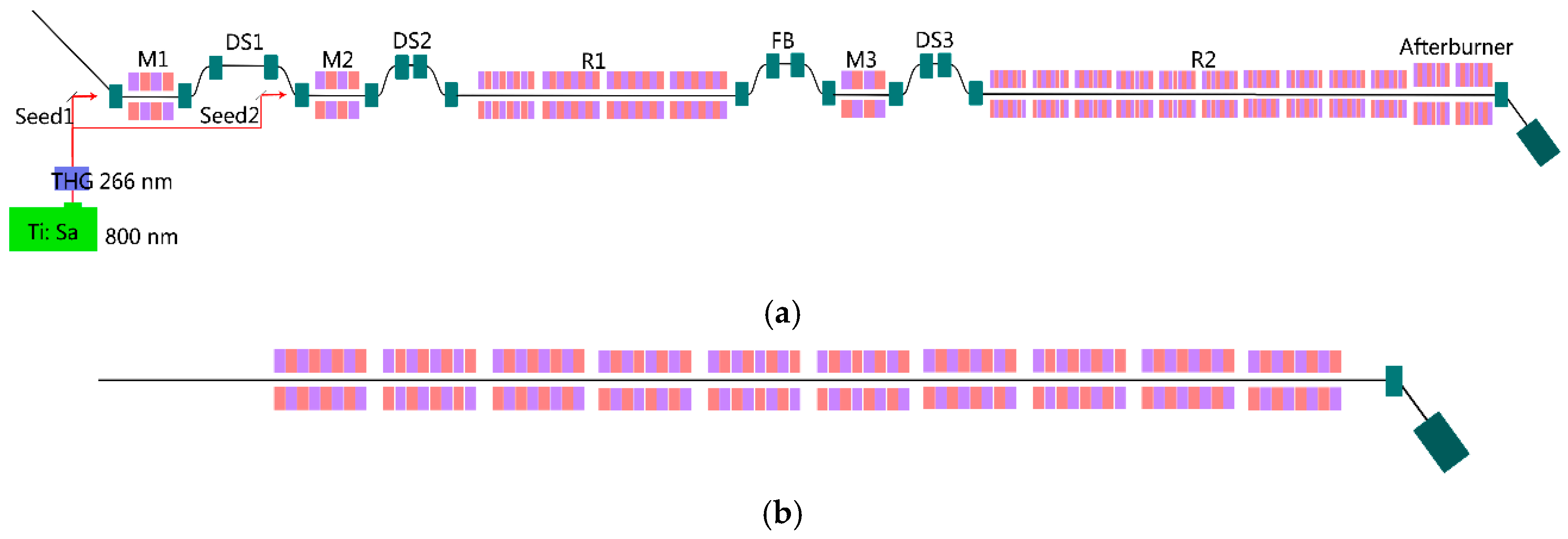
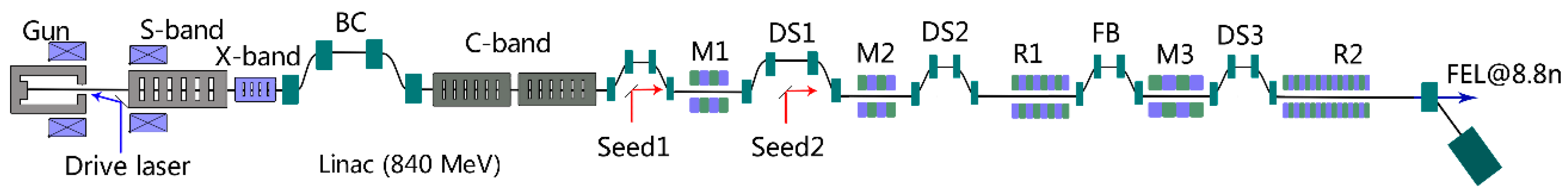
2.1. Layout and Main Parameters
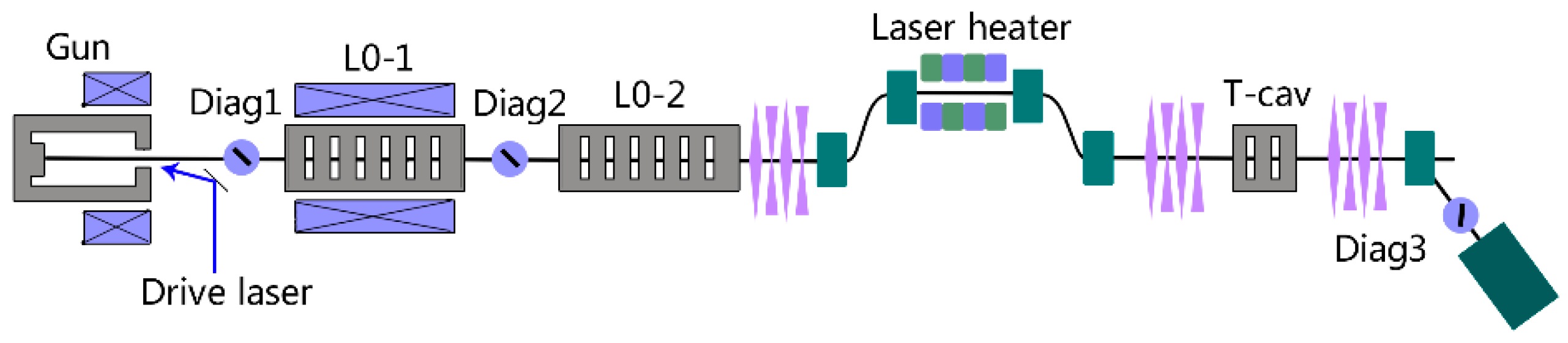
The SXFEL-TF consists of an 840 MeV electron linac and a two-stage cascaded seeding scheme-based undulator system, as shown in Figure 1. The initial proposal of the SXFEL-TF project in 2016 was to test the cascaded HGHG scheme [25]. In the following years, it was gradually optimized and more contents of the EEHG were added to the project when the construction started in 2014. A new cascaded EEHG-HGHG operation scheme was incorporated into the SXFEL-TF to further improve the ultra-high harmonic up-conversion efficiency.
The main parameters of the SXFEL-TF are shown in Table 1. The wavelength of the seeding laser used in the first stage is 265 nm. The output radiation wavelength from the first stage is about 44 nm. In the second stage, an 8.8 nm soft X-ray FEL radiation pulse will be eventually produced based on the HGHG scheme. The total harmonic up-conversion number of the two stages is 30.

2.2. Injector

The SXFEL photo-injector, as shown in Figure 2, consists of an S-band photo-cathode radio frequency (RF) gun, emittance compensating solenoids, a drive laser, two S-band accelerating structures, and a laser heater. To generate a flat-top driving laser pulse, the pulse stacking technique is adopted in the temporal shaping system. Three diagnostic stations are employed in the injector. The 6D phase space of the electron bunch can be reconstructed by the combination of a transverse deflecting cavity and a 2-cell FODO lattice, each cell contains a focusing quadrupole (F), a space (O), a defocusing quadrupole (D) and a space (O).
The beam parameters at the exit of the injector are shown in Table 2. The injector aims at achieving sub-μm level normalized emittance with the bunch charge of 0.5 nC, and the operation parameter errors of photo-cathode gun, drive laser, solenoids, and accelerating structures are well controlled to make sure the beam parameters lie within the specifications.

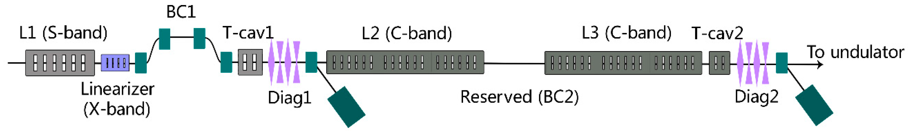
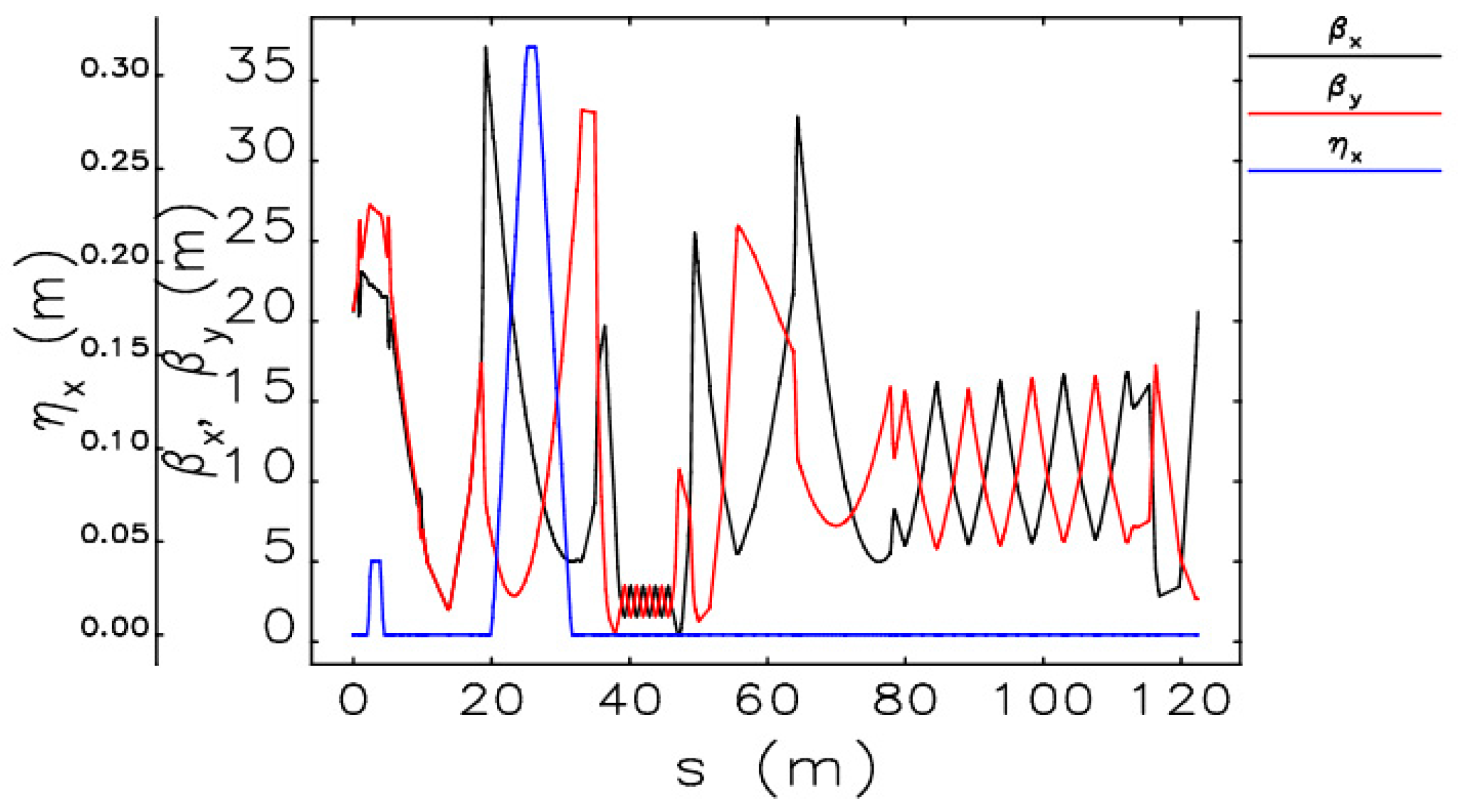
2.3. Main Accelerator

The main accelerator of the SXFEL-TF is designed as a compact linac with high-gradient C-band RF accelerating structures. Initially, the main linac consists of 3 linac sections (L1 to L3) and two bunch compressors [25]. Later on, the two-stage bunch compression scheme was replaced by a single-stage bunch compressor with BC1 at a beam energy of approximately 200 MeV, based on the experience of FERMI. Currently, the main linac layout is shown in Figure 3, where L1 is the S-band accelerating section and L2 and L3 are C-band accelerating sections. To further boost the electron beam energy up to 1.5 GeV in the future, extra space between L2 and L3 has been reserved, in which a second bunch compressor and more C-band structures can be installed.
C-band accelerating structures have the advantage of compensating the energy spread at the phase around the crest due to the stronger longitudinal wakefield, and this, as a result, can reduce the beam energy jitter. In the meantime, simulation suggests that the transverse wakefield of the C-band structure will not obviously degrade the beam performance. Designed parameters for the main linac are shown in Table 3.
In order to monitor the beam positions and optics, beam position monitors (BPMs) and beam profilers are used in the main linac. In the first bunch compressor (BC1), non-destructive bunch length and beam energy detectors are installed to give feedback on the beam energy, peak current, and arrival time with the Low-level RF system.
The triplets and FODO lattices are arranged for the main linac. Figure 4 shows the Twiss functions calculated by the ELEGANT program [27]. To minimize the horizontal beta function at the last bending magnet and hence mitigate the CSR effect, two doublets are used on each arm of the chicane. After L2, there is some extra space reserved for accommodating C-band accelerating structures for upgrading the linac energy in the future.

2.4. Undulator Line

The main purpose of the SXFEL-TF is to test two-stage harmonic generation, such as the HGHG-HGHG or EEHG-HGHG cascading schemes. As shown in Figure 5, the undulator system consists of a seed laser system, three modulators, two radiator sections, and a couple of chicanes serving for laser injection, dispersive section, and fresh bunch delay purposes.
The electron bunch at the exit of the linac is about 1 ps (FWHM) long. A small part is modulated in the modulators by a seed laser pulse with a pulse length of about 100 fs (FWHM), and the modulated part of the electron bunch generates coherent radiation in the first stage radiator. This radiation is shifted ahead to a fresh part of the electron bunch by the fresh bunch chicane and serves as the seed for the following stage. A short undulator of the same type as the first stage radiator is employed as the modulator and a small chicane is used as the dispersion section in the second stage. The harmonic up-conversion numbers of the two stages are six and five, respectively, which makes the final output wavelength ~8.8 nm.

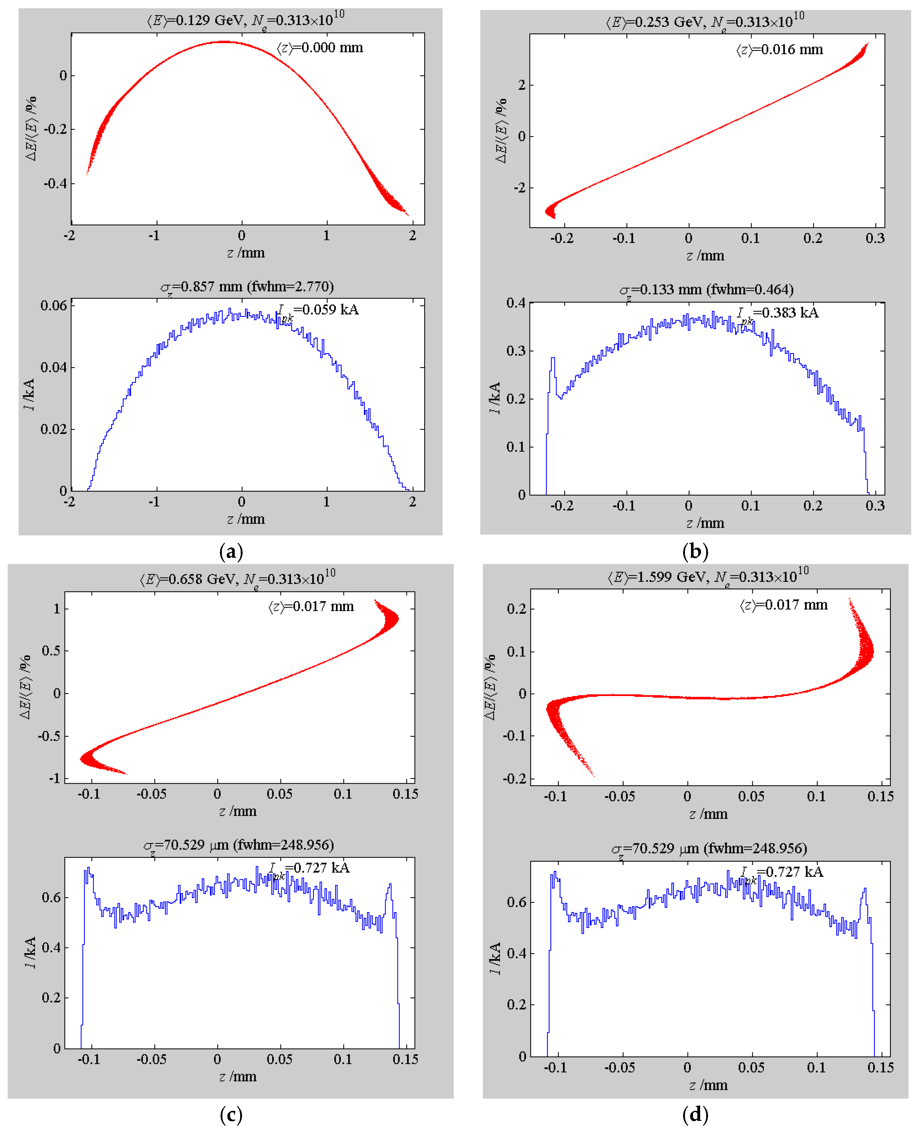
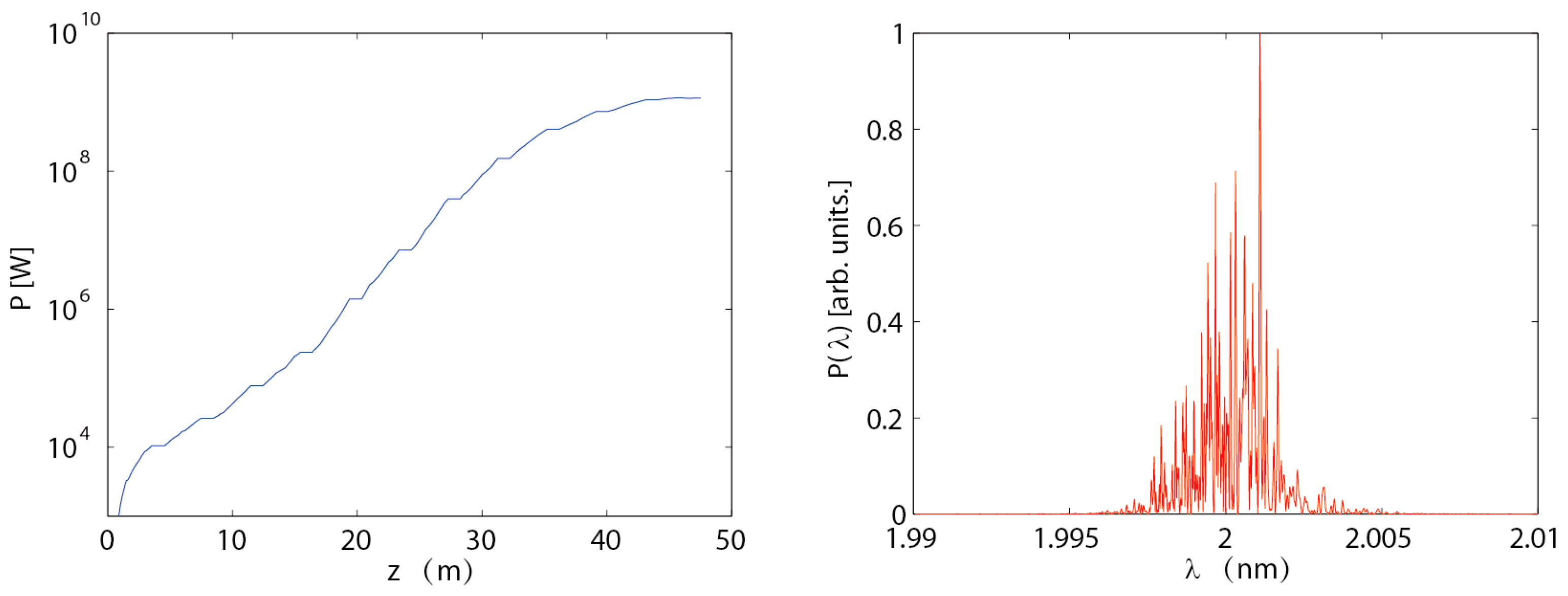
2.5. Performance of the SXFEL-TF

The SXFEL-TF has been designed and constructed to be a flexible facility for testing various advanced FEL seeding concepts. A number of different operating modes have been considered for the SXFEL-TF. Here we only present some typical results for the two-stage HGHG cascade, the EEHG-HGHG cascade and single stage EEHG. More details of the simulations can be found in references [26,28].
Using the parameters listed in Table 1, Figure 6 shows the simulation results for the cascaded HGHG. The simulations were carried out by the time-dependent mode of GENESIS [29]. The seed power used for the first stage HGHG is about 200 MW. The whole electron beam was tracked though the two stages to obtain realistic simulation results. One can find in Figure 6 that a coherent soft X-ray radiation pulse at 8.8 nm with peak power exceeding 200 MW can be produced through the two-stage HGHG scheme.
Besides the conventional cascaded HGHG, we also want to perform some proof-of-principle experiments for novel schemes. As shown in Figure 1, the first stage of the SXFEL-TF is a typical EEHG, which employs two modulator-chicane sections to introduce the echo effect into the electron beam. Therefore, the SXFEL provides a perfect platform for testing the cascaded EEHG-HGHG scheme. The simulation results for this scheme are shown in Figure 7.
Moreover, we also have the plan of operating a single-stage EEHG at ultra-high harmonics for directly generating the 8.8 nm radiation pulse [29]. The main simulation results for this case are shown in Figure 8. In the single stage EEHG, long seed laser pulses can be adopted to fully cover the electron bunch, which results in a much higher output pulse energy and much narrower output bandwidth.

2.6. Construction, Installation and Commissioning of the SXFEL-TF

Construction of the SXFEL-TF started in December 2014. One year later, 547 pile foundations, a total area of about 7000 m2 of civil construction, and a concrete tunnel were completed. The building was ready for machine installation in April 2016 and then installation started. Figure 9 and Figure 10 show the status of the construction and installation at the SXFEL-TF site.
Installation of the linac, the undulator system, and the diagnostic beamline was almost completed by the end of 2016. The linac RF conditioning and beam commissioning started in late December 2016. The beam was then successfully accelerated to 700 MeV at the exit of the C-band linac and sent to the undulator line to check the installation and equipment’s function. The electron beam went through the radiator undulators and the spontaneous undulator radiation at wavelength about 15 nm was characterized with the photodiode and X-ray charge-coupled-device camera at the diagnostic beamline on 31 December 2016. The RF conditioning of the C-band linac and the commissioning of the S-band injector have been performed at the same time. The normalized emittance of the injector electron beam at about 200 MeV and after the magnetic bunch compressor BC1 is 1.2 mm·mrad and 1.1 mm·mrad in the horizontal and vertical directions, respectively. Further optimization to achieve FEL lasing is ongoing.

3. The SXFEL User Facility

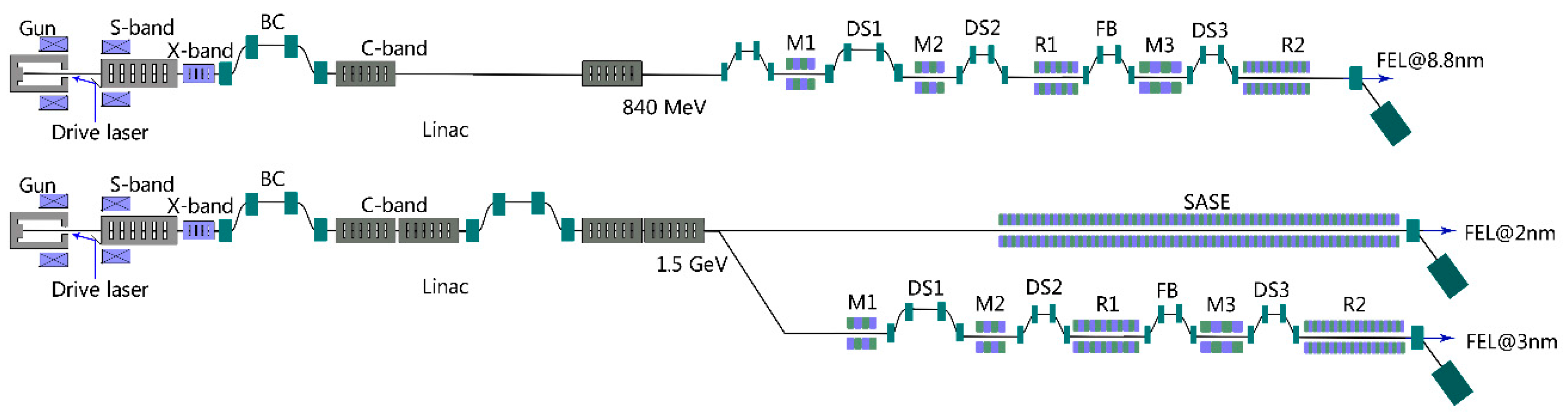
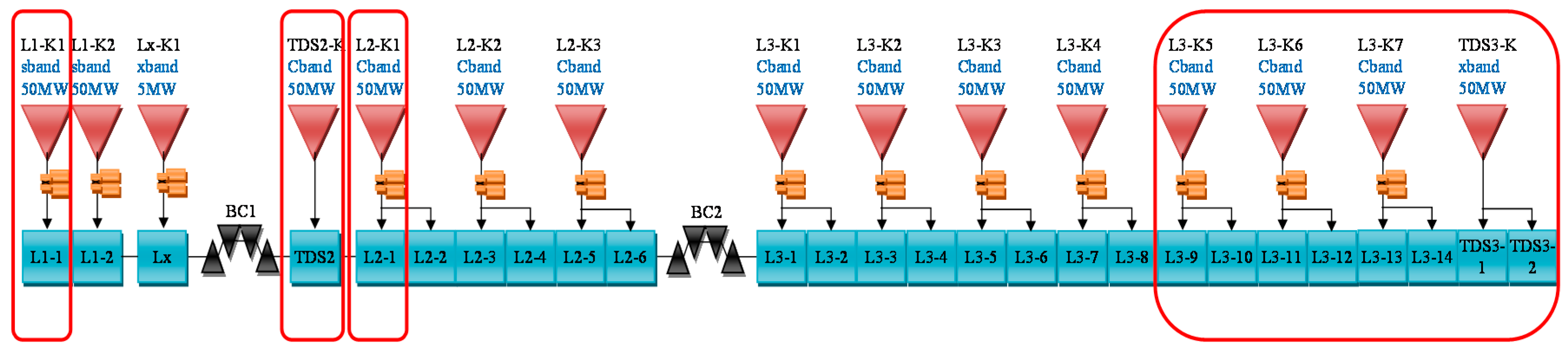
3.1. Layout and Parameters

The SXFEL-TF will be upgraded to the soft X-ray user facility, SXFEL-UF, with the radiation wavelength extended to cover the water window region by boosting the electron beam energy to 1.5 GeV with more C-band accelerating structures. Two undulator lines, their associated beamlines, and five experimental end-stations are under construction for user experiments. The layout comparison between the SXFEL-TF and the SXFEL-UF is shown in Figure 11. Table 4 lists the main basic parameters of the SXFEL-UF.

3.2. Energy Upgrade

The main linac of the SXFEL-UF will accelerate the electron beam from an energy of 130 MeV at the exit of the injector to 1.5 GeV at the end of the linac. In this process, the electron bunch length will be compressed from 10 ps to about 0.7 ps. As shown in Figure 12, an additional set of S-band 50 MW RF power source in section L1, four C-band accelerating units with eight RF accelerating structures, and a second bunch compressor section (BC2) are added to SXFEL-TF in its reserved space between L2 and L3 to constitute the SXFEL-UF main linac. In this upgrade, an X-band transverse deflecting cavity is placed at the end of this linac to obtain high resolution bunch length measurement at higher energy. The designed working parameters are shown in Table 5 and the simulated beam distributions are shown in Figure 13.

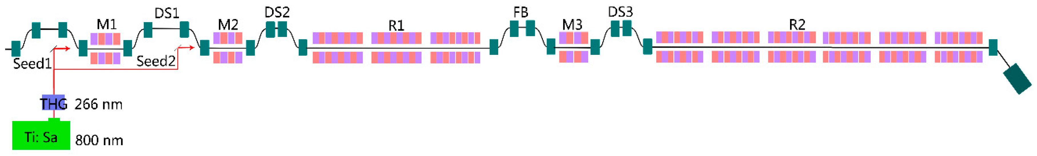
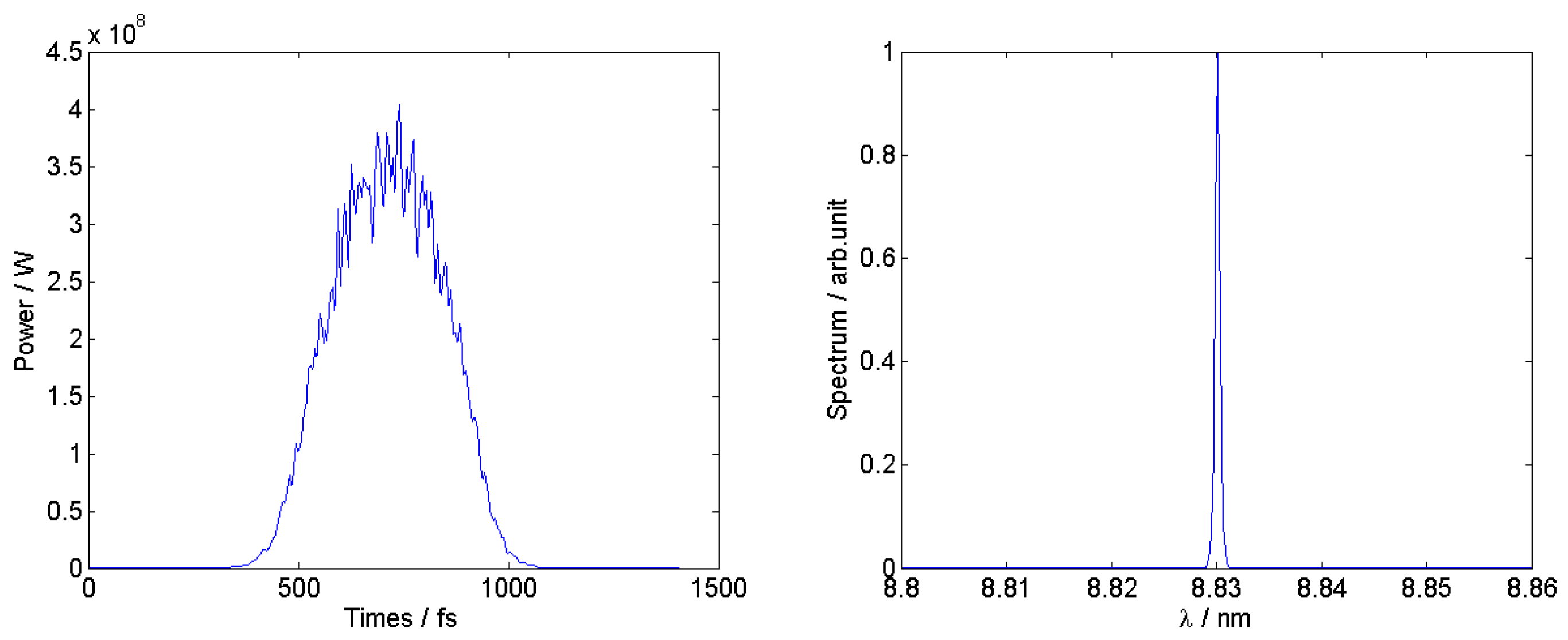
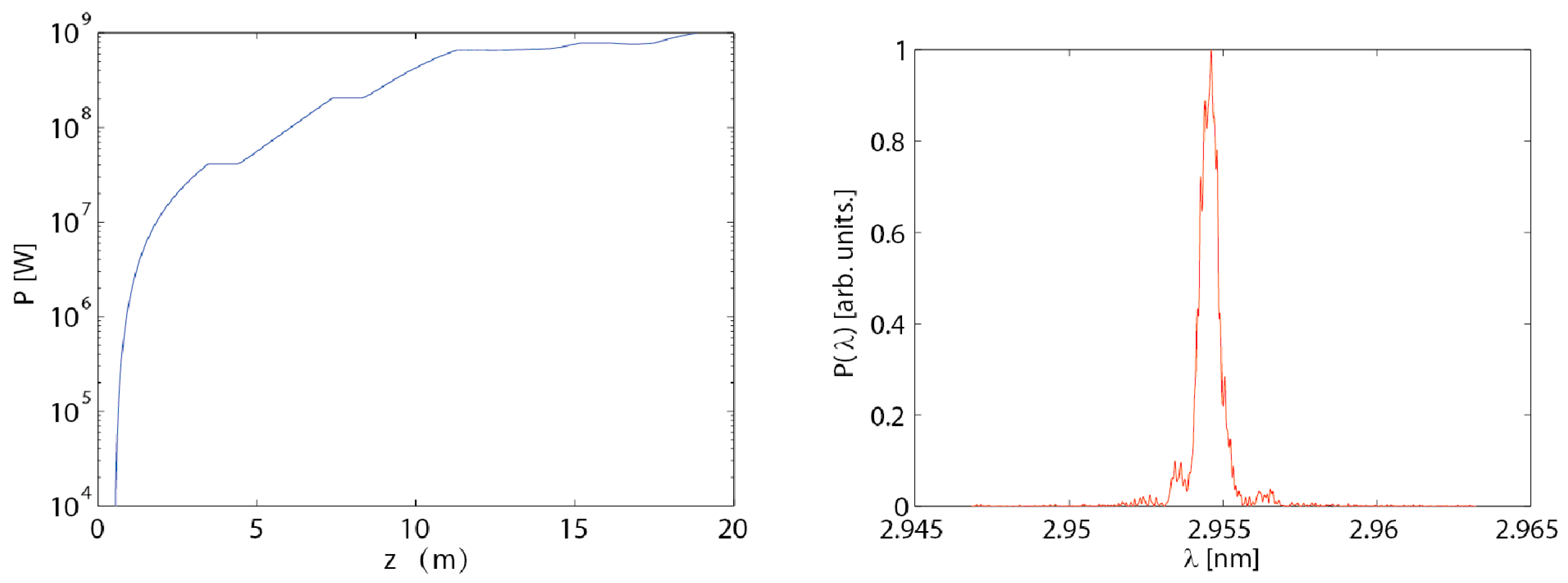
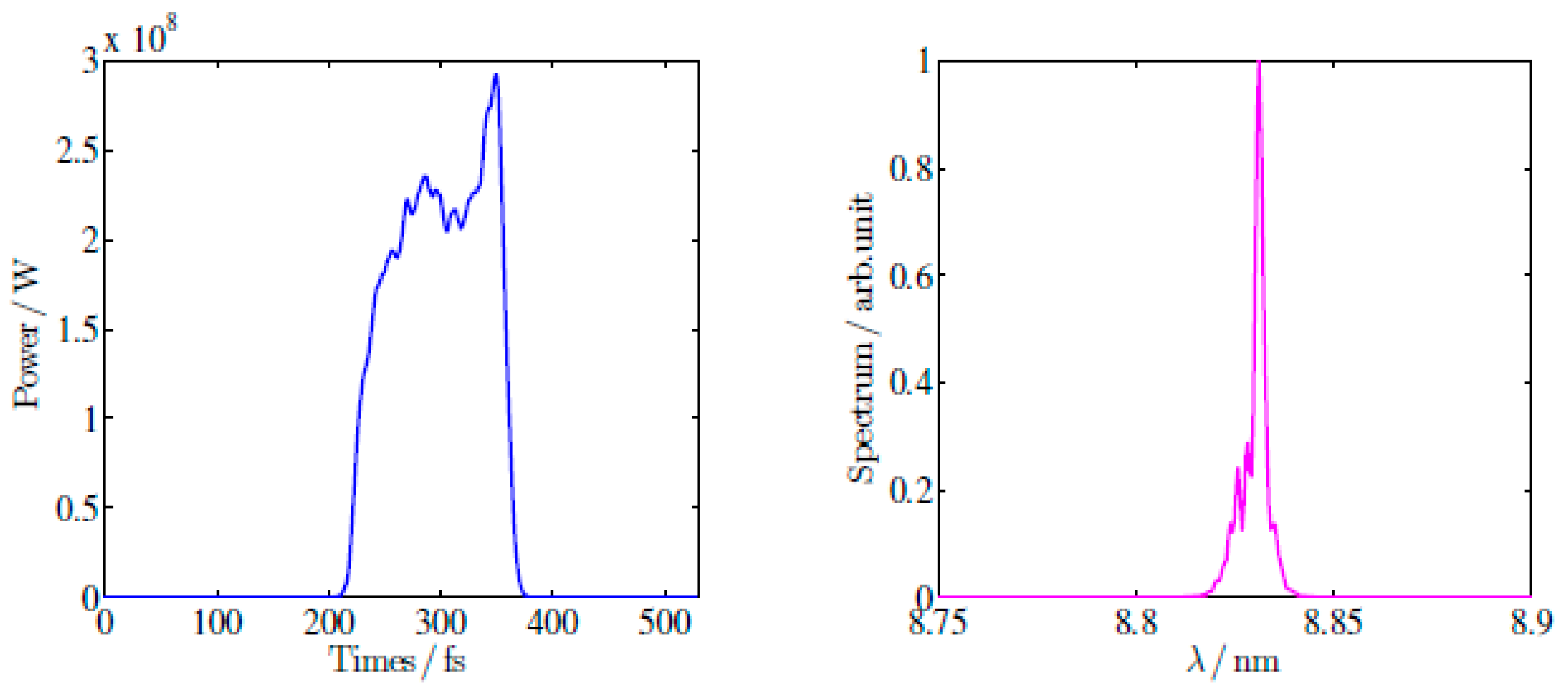
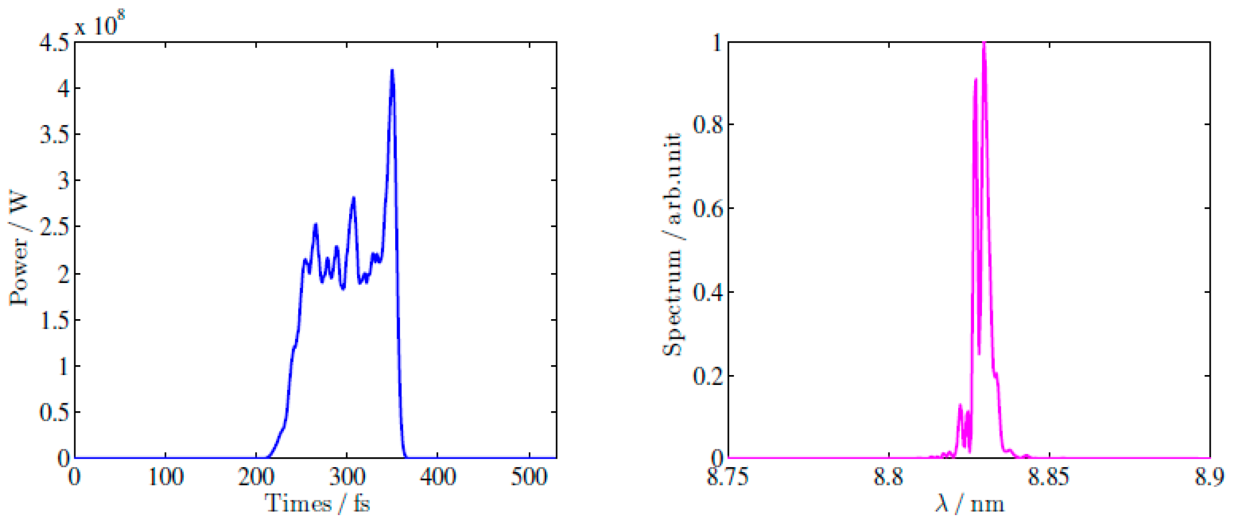
3.3. Undulator Lines and the FEL Performance

There are two undulator lines for the user facility. One is upgraded from the test facility and will be operated with either a cascaded HGHG or EEHG-HGHG mode, as shown in Figure 14a, and hereafter referred to as the seeded line, while the other will be a brand-new line operated in the SASE mode, as shown in Figure 14b.
With the beam energy boosted to 1.5 GeV and the peak current increased to 700 A, the output wavelength of the SXFEL-UF can cover the water window region. Accordingly, to make the FEL output of the seeded line saturate, the length of the original undulator line should be increased. Here, one radiator is added in the first stage and four planar undulators are added in the second stage. With such a configuration, a fully coherent saturated 3 nm FEL output could be obtained. To fulfill users’ demands, two elliptical polarized undulators (EPU) will be added following the radiators of the second stage to form the so-called “afterburner” scheme and realize the full control of the soft X-ray FEL’s polarization.
In the baseline design, the second undulator line is based on the SASE mode, and the undulator is the in-vacuum planar type. The undulator period is 16 mm and the working gap is around 3.7 mm, resulting in a K value of 1.8. For this undulator line, the final FEL output is around 8 nm at a beam energy of 840 MeV, and can be as low as 2 nm at a beam energy of 1.5 GeV, while the output peak power will be greater than 100 MW for both cases.
With the parameters shown in Table 4, the SXFEL-UF’s performance with different undulator lines was simulated with the time-dependent mode of GENESIS. A 265 nm laser pulse with a longitudinal Gaussian profile, 200 MW peak power, and 100 fs (FWHM) pulse length is used as the seed laser for the seeded line. To obtain realistic simulation results, the whole electron beam was tracked through the undulator lines. The simulation results are illustrated in Figure 15 for the seeded line with the cascaded HGHG-HGHG mode, and in Figure 16 for the SASE line.

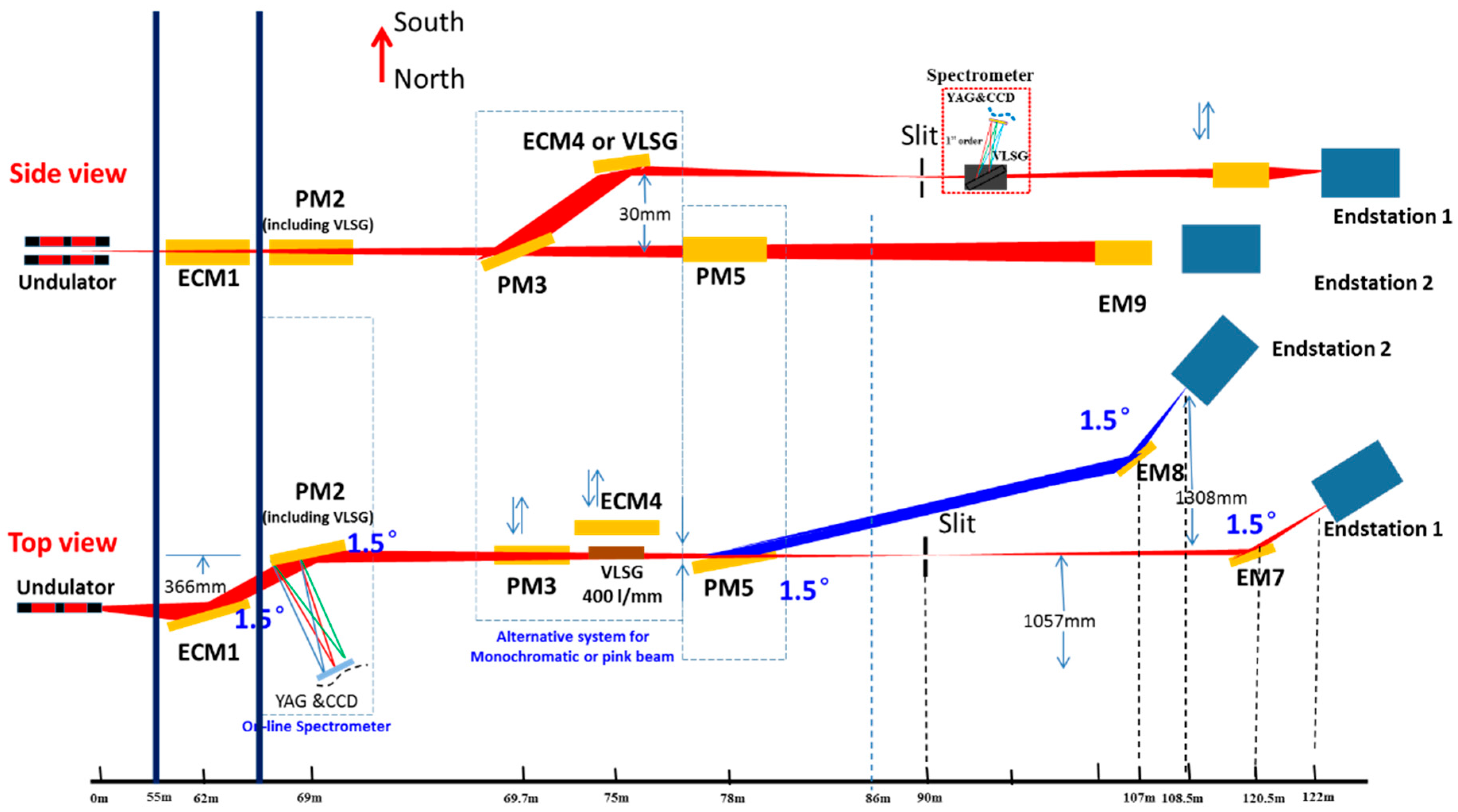
3.4. Beamlines and Experimental End-Stations

X-ray beamlines are important parts of the SXFEL user facility, precisely transmitting the FEL output into various end-stations. Online diagnostics of the FEL outputs will also be provided at the beamlines. In the initial phase of the user facility, there are two beamlines and five end-stations, including cell imaging, atomic molecular and optical physics (AMO), ultrafast physics, surface chemistry, etc. Figure 17 shows one of the SXFEL-UF beamlines together with two end-stations.
With its high light source performance properties and these well-designed instruments, SXFEL is dedicated to ultrafast X-ray science and fundamental research, especially on femtosecond chemistry, materials under extreme conditions, high-throughput bio-imaging, light-induced transient phenomenon and dynamic functions in real time, etc. Owing to its ultra-intense and ultrafast pulses, the facility will attract much attention from the science community and this will be the main driving force for the SXFEL.
To make use of the full coherence and femtosecond pulse duration of XFEL, technologies such as ultrafast scattering and imaging will be employed. Ultrafast scattering and imaging with unprecedented spatial resolution will permit the evolution of nano-materials, and will allow further investigation of the relationship between material synthesis and operating conditions. This will change our methods for the development of novel materials. Moreover, the capability of SXFEL will enable the unique characterization of structure and dynamic changes therein. Electron transfer, electronic fluctuation, transient phase transfer and hidden phase could be captured in a few femtoseconds. The ability to capture ultrafast processes will give a better understanding of motions at the sub-nanometer and femtosecond scales. Flash X-ray imaging, combined with intense lasers and mass spectroscopy, could be applied to bio-imaging and the investigation of materials under extreme conditions. To obtain the special properties of catalysis and photo-catalysis, methods such as laser-pump X-ray probing and two-color X-ray pump X-ray probing may achieve surprising results. Considering dynamic functions under natural states and in real time is the key to investigating any ultrafast problems. To this end, multiple pump-probes (Vis-/infrared-laser, THz, X-ray) with mixed particle injectors will be designed to capture high frame rates images. The understanding of any emergent phenomena is essential for designing new materials and chemical reactions. To cover this issue, SXFEL will reveal these critical events step by step, from scattering and diffraction to absorption. The data from different end-stations either specially-designed or based on general X-ray technologies at SXFEL will be combined. Multiple big data analyses would provide new ways to approach new materials and chemical reactions.

3.5. Construction and Project Schedule

The civil construction of the SXFEL-UF undulator tunnel and experimental hall started in November 2016. Procurement of the main components for the energy upgrade and new undulators is underway and on schedule. The civil construction will be finished in July 2018, and will be followed by the installation and commissioning of the apparatus. User experiments are expected to commence in early 2019.

4. Conclusions

The SXFEL (both the test facility and the user facility) projects are in good shape. The SXFEL-TF is under commissioning, aiming to commence lasing in the first half of 2017. The test facility will be quickly upgraded to a soft X-ray user facility by boosting the beam energy to 1.5 GeV, constructing two undulator lines and five experimental stations, and adding a new undulator tunnel and experimental hall. The SXFEL-UF started its civil construction in November 2016 and will provide high-brightness and ultrafast soft X-ray FEL beams covering the full water window to the user community in 2019.

Acknowledgments

The authors thank the whole FEL team in the Shanghai Institute of Applied Physics for their excellent support during the past decades, who made invaluable contributions and dedications to the design, construction, and commissioning of SXFEL. We also thank Zhi Liu and Huaidong Jiang for the science programs of the SXFEL user facility. Thanks also go to Senyu Chen, Li-Hua Yu, Zhirong Huang, Gennady Stupakov and Alexander Wu Chao for useful discussions and their continuous encouragement. This work was partially supported by the National Development and Reform Commission ([2013]2347) and the National Basic Research Program of China (2015CB859700).

Author Contributions

Zhentang Zhao, Dong Wang, Qiang Gu, Lixin Yin, Ming Gu, Yongbin Leng and Bo Liu led the design, construction and commissioning of the SXFEL. Qiang Gu and Bo Liu were in charge of the numerical simulations. All authors co-wrote the paper.

Conflicts of Interest

The authors declare no conflict of interest.

References

  1. Ackermann, W.A.; Asova, G.; Ayvazyan, V.; Azima, A.; Baboi, N.; Bähr, J.; Balandin, V.; Beutner, B.; Brandt, A.; Bolzmann, A.; et al. Operation of a free-electron laser from the extreme ultraviolet to the water window. Nat. Photonics 2007, 1, 336–342. [Google Scholar] [CrossRef]
  2. Emma, P.; Akre, R.; Arthur, J.; Bionta, R.; Bostedt, C.; Bozek, J.; Brachmann, A.; Bucksbaum, P.; Coffee, R.; Decker, F.-J.; et al. First lasing and operation of an ångstrom-wavelength free-electron laser. Nat. Photonics 2010, 4, 641–647. [Google Scholar] [CrossRef]
  3. Ishikawa, T.; Aoyagi, H.; Asaka, T.; Asano, Y.; Azumi, N.; Bizen, T.; Ego, H.; Fukami, K.; Fukui, T.; Furukawa, Y.; et al. A compact X-ray free-electron laser emitting in the sub-angstrom region. Nat. Photonics 2012, 6, 540–544. [Google Scholar] [CrossRef]
  4. Han, J.H.; Kang, H.S.; Ko, I.S. Status of the PAL-XFEL project. In Proceedings of the IPAC2012, New Orleans, LA, USA, 20–25 May 2012; pp. 1735–1737. [Google Scholar]
  5. Ganter, R. SwissFEL-Conceptual Design Report; No. PSI-10-04; Paul Scherrer Institute (PSI): Villigen, Switzerland, 2010. [Google Scholar]
  6. Massimo, A. The European X-ray Free-Electron laser: Technical Design Report; European XFEL Project Team: Hamburg, Germany, 2013. [Google Scholar]
  7. Kondratenko, A.M.; Saldin, E.L. Generating of coherent radiation by a relativistic electron beam in an ondulator. Part. Accel. 1980, 10, 207–216. [Google Scholar]
  8. Bonifacio, R.; Pellegrini, C.; Narducci, L.M. Collective instabilities and high-gain regime in a free electron laser. Opt. Commun. 1984, 50, 373–378. [Google Scholar] [CrossRef]
  9. Yu, L.-H. Generation of intense uv radiation by subharmonically seeded single-pass free-electron lasers. Phys. Rev. A 1991, 44, 5178. [Google Scholar] [CrossRef] [PubMed]
  10. Wu, J.H.; Yu, L.H. Coherent Hard X-ray Production by Cascading Stages of High Gain Harmonic Generation X-ray FEL. Nucl. Instrum. Methods A 2001, 475, 104–111. [Google Scholar] [CrossRef]
  11. Stupakov, G. Using the Beam-Echo Effect for Generation of Short-Wavelength Radiation. Phys. Rev. Lett. 2009, 102, 074801. [Google Scholar] [CrossRef] [PubMed]
  12. Xiang, D.; Stupakov, G. Enhanced tunable narrow-band THz emission from laser-modulated electron beams. Phys. Rev. STAB 2009, 12, 256–273. [Google Scholar] [CrossRef]
  13. Deng, H.; Feng, C. Using off-resonance laser modulation for beam-energy-spread cooling in generation of short-wavelength radiation. Phys. Rev. Lett. 2013, 111, 084801. [Google Scholar] [CrossRef] [PubMed]
  14. Feng, C.; Deng, H.; Wang, D.; Zhao, Z. Phase-merging enhanced harmonic generation free-electron laser. New J. Phys. 2014, 16, 043021. [Google Scholar] [CrossRef]
  15. Feldhaus, J.; Saldin, E.L.; Schneider, J.R.; Schneidmiller, E.A.; Yurkov, M.V. Possible application of X-ray optical elements for reducing the spectral bandwidth of an X-ray SASE FEL. Nucl. Instrum. Methods Phys. Res. Sect. A 1997, 393, 162–166. [Google Scholar] [CrossRef]
  16. Geloni, G.; Kocharyan, V.; Saldin, E. A novel self-seeding scheme for hard X-ray FELs. J. Mod. Opt. 2011, 58, 1391–1403. [Google Scholar] [CrossRef]
  17. Amann, J.; Berg, W.; Blank, V.; Decker, F.J.; Ding, Y.; Emma, P.; Feng, Y.; Frisch, J.; Fritz, D.; Hastings, J.; et al. Demonstration of self-seeding in a hard-X-ray free-electron laser. Nat. Photonics 2012, 6, 693–698. [Google Scholar] [CrossRef]
  18. Ratner, D.; Abela, R.; Amann, J.; Behrens, C.; Bohler, D.; Bouchard, G.; Bostedt, C.; Boyes, M.; Chow, K.; Cocco, D.; et al. Experimental demonstration of a soft x-ray self-seeded free-electron laser. Phys. Rev. Lett. 2015, 114, 054801. [Google Scholar] [CrossRef] [PubMed]
  19. Yu, L.-H.; Babzien, M. High-gain harmonic-generation free-electron laser. Science 2000, 289, 932–935. [Google Scholar] [CrossRef] [PubMed]
  20. Zhao, Z.T.; Wang, D.; Chen, J.H.; Chen, Z.H.; Deng, H.X.; Ding, J.G.; Feng, C.; Gu, Q.; Huang, M.M.; Lan, T.H.; et al. First lasing of an echo-enabled harmonic generation free-electron laser. Nat. Photonics 2012, 6, 360–363. [Google Scholar] [CrossRef]
  21. Liu, B.; Li, W.B.; Chen, J.H.; Chen, Z.H.; Deng, H.X.; Ding, J.G.; Fan, Y.; Fang, G.P.; Feng, C.; Feng, L.; et al. Demonstration of a widely-tunable and fully-coherent high-gain harmonic-generation free-electron laser. Phys. Rev. Spec. Top. Accel. Beams 2013, 16, 020704. [Google Scholar] [CrossRef]
  22. Allaria, E.; Appio, R.; Badano, L.; Barletta, W.A.; Bassanese, S.; Biedron, S.G.; Borga, A.; Busetto, E.; Castronovo, D.; Cinquegrana, P.; et al. Highly coherent and stable pulses from the FERMI seeded free-electron laser in the extreme ultraviolet. Nat. Photonics 2012, 6, 699–704. [Google Scholar] [CrossRef]
  23. Boedewadt, J.; Ackermann, S.; Aßmann, R.; Ekanayake, N.; Faatz, B.; Feng, G.; Hartl, I.; Ivanov, R.; Amstutz, P.; Azima, A.; et al. Recent results from FEL seeding at FLASH. In Proceedings of the IPAC2015, Richmond, VA, USA, 3–8 May 2015; pp. 1366–1369. [Google Scholar]
  24. Allaria, E.; Castronovo, D.; Cinquegrana, P.; Craievich, P.; Dal Forno, M.; Danailov, M.B.; D’Auria, G.; Demidovich, A.; De Ninno, G.; Di Mitri, S.; et al. Two-stage seeded soft-X-ray free-electron laser. Nat. Photonics 2013, 7, 913–918. [Google Scholar] [CrossRef]
  25. Zhao, Z.T.; Chen, S.Y.; Yu, L.H.; Tang, C.X.; Yin, L.X.; Wang, D.; Gu, Q. Shanghai soft X-ray free electron laser test facility. In Proceedings of the IPAC2011, San Sebastián, Spain, 4–9 September 2011; pp. 3011–3013. [Google Scholar]
  26. Zhao, Z.T.; Wang, D.; Yin, L.X.; Gu, Q.; Fang, G.P.; Liu, B. The current status of the SXFEL project. AAPPS Bull. 2016, 26, 12–24. [Google Scholar]
  27. Borland, M. Elegant: A Flexible SDDS-Compliant Code for Accelerator Simulation; Technical Report No. LS-287; Advanced Photon Source: Argonne, IL, USA, 2000. [Google Scholar]
  28. Feng, C.; Huang, D.; Deng, H.; Chen, J.; Xiang, D.; Liu, B.; Wang, D.; Zhao, Z. A single stage EEHG at SXFEL for narrow-bandwidth soft X-ray generation. Sci. Bull. 2016, 61, 1202–1212. [Google Scholar] [CrossRef]
  29. Reiche, S. GENESIS 1.3: A fully 3D time-dependent FEL simulation code. Nucl. Instrum. Methods A 1999, 429, 243–248. [Google Scholar] [CrossRef]
Figure 1. Schematic layout of the Shanghai soft X-ray Free-Electron Laser Test Facility (SXFEL-TF), including a photo-cathode injector, a main linac, and an undulator system (BC: bunch compressor, M: modulator, DS: dispersion section, R: radiator, FB: fresh bunch).
Applsci 07 00607 g001
Figure 2. Layout of the SXFEL injector. (Reprint from reference [26]).
Applsci 07 00607 g002
Figure 3. Layout of the main linac of the SXFEL-TF. (Reprint from reference [26]).
Applsci 07 00607 g003
Figure 4. Twiss functions along the main linac.
Applsci 07 00607 g004
Figure 5. Layout of the undulator line.
Applsci 07 00607 g005
Figure 6. Simulated FEL performances of cascaded high-gain harmonic generation (HGHG) at the SXFEL-TF: final output pulse at 8.8 nm in time (left) and spectral (right) domain.
Applsci 07 00607 g006
Figure 7. Simulated FEL performances of the cascaded echo-enabled harmonic generation (EEHG)-HGHG scheme at the SXFEL-TF: final output pulse at 8.8 nm in time (left) and spectral (right) domain.
Applsci 07 00607 g007
Figure 8. Simulated FEL performances of a single stage EEHG at the SXFEL-TF: final output pulse at 8.8 nm in time (left) and spectral (right) domain.
Applsci 07 00607 g008
Figure 9. Bird’s eye view of the SXFEL-TF site.
Applsci 07 00607 g009
Figure 10. The SXFEL linac (left) and undulator (right).
Applsci 07 00607 g010
Figure 11. Schematic layouts: SXFEL-TF (upper) and Shanghai soft X-ray Free-Electron Laser User Facility (SXFEL-UF) (lower).
Applsci 07 00607 g011
Figure 12. Layout of the main linac of the SXFEL-UF. (Reprint from reference [26]).
Applsci 07 00607 g012
Figure 13. Simulation results of the electron beam distributions: energy distributions and current profiles at (a) injector exit; (b) BC1 exit; (c) BC2 exit and (d) L3 exit.
Applsci 07 00607 g013
Figure 14. Schematic layout of the FEL undulator lines for the SXFEL-UF: (a) Seeded line of the SXFEL-UF (upgraded from SXFEL-TF); (b) new undulator line for the SXFEL-UF.
Applsci 07 00607 g014
Figure 15. Simulated FEL performance of the seeded line at 3 nm output: gain curve and the output spectrum.
Applsci 07 00607 g015
Figure 16. Simulated FEL performance of the SASE line at 2 nm output: gain curve and the output pulse in the time domain.
Applsci 07 00607 g016
Figure 17. A typical beamline with two end-stations.
Applsci 07 00607 g017
Table 1. Main parameters of the SXFEL-TF. (Reprint from reference [26]).
LinacValues
Electron energy840 MeV
Energy spread (rms)≤0.1%
Normalized emittance (rms)≤1.5 mm·mrad
Bunch length (FWHM)≤1.0 ps
Bunch charge0.5 nC
Peak current at undulator≥500 A
Pulse repetition rate10 Hz
Undulator
Stage 1
Seed laser wavelength265 nm
FEL output wavelength44 nm
Modulator undulator period80 mm
Modulator undulator K value5.81
Radiator undulator period40 mm
Radiator undulator K value2.22
Stage 2
FEL output wavelength8.8 nm
Modulator undulator period40 mm
Modulator undulator K value2.22
Radiator undulator period23.5 mm
Radiator undulator K value1.43
Table 2. Main electron beam parameters of the SXFEL injector. (Reprint from reference [26]).
ParametersValue
Electron energy130 MeV
Bunch charge0.5 nC
Projected emittance (rms)0.95 mm·mrad
Central slice emittance (rms)0.65 mm·mrad
Bunch length (FWHM)~10 ps
Projected energy spread (rms)0.14%
Table 3. Designed working parameters of the main linac. (Reprint from reference [26]).
ParametersL1LXL2L3
Effective accelerating gradient (MV/m)15253232
Accelerating phase (deg)−52.6−1801414
Energy at the section exit (MeV)184165389840
Table 4. Main parameters of the SXFEL-UF.
LinacValues
Electron energy1500 MeV
Energy spread (rms)≤0.1%
Normalized emittance (rms)≤1.5 mm·mrad
Bunch charge0.5 nC
Peak current at undulator≥700 A
Pulse repetition rate50 Hz
Undulator
Line 1
FEL operation modeSASE
FEL output wavelength~2 nm
FEL output pulse peak power≥100 MW
Line 2
FEL operation modeExternal seeding
FEL output wavelength~3 nm
FEL output pulse peak power≥100 MW
Table 5. Designed working parameters of the main linac for SXFEL-UF.
Linac ComponentsEout (MeV)σz-Out (mm)σδ-Out (%)E (MV/m)фrf\Θbend (Deg)R56 (mm)
L01300.860.14 --
L12730.861.4427−29.2-
X2560.861.5119180-
BC1-0.13- 3.968−48
L26400.130.42384-
BC2-0.07- 2.217–15
L315000.070.028386-

