1. Introduction
Storage tanks are widely employed in civil, marine, and automotive fields, etc., to store water, oil, fuel, chemicals, and other fluids. In order to withstand the internal high pressures, a storage tank is generally designed in a cylindrical [
1,
2,
3,
4,
5,
6,
7], oval [
8,
9], or spherical [
10] shape. This structure and shape affects the performance of the storage tank. A poor design will cause accidental deformation and rupture of the storage tank [
3,
5]. Thus, the design, optimization, and analysis of storage tanks have received considerable attention from many researchers.
Rastgar and Showkati [
11] studied storage tanks at a refinery site by experimentation and finite element analysis (FEA) models. The results show that tanks with oblique body imperfections exhibit high initial strength against buckling due to a uniform external pressure. Azzuni and Guzey [
12] investigated a diameter limit for use in the design of the top stiffener ring for above-ground storage tanks using finite-element analysis in a parametric study. The results show that the suitable upper limit to design the top stiffener rings can be increased. Vathi et al. [
13] proposed performance criteria for the seismic design of industrial liquid storage tanks and their piping systems, and it can provide a method to introduce industrial components into a performance-based design framework. Sweedan and Damatty [
14] developed a simplified design approach to ensure the safety of hydrostatically-loaded combined steel conical tanks against buckling. Numerical examples were presented to explain the application of the suggested design approach. Musa and Damatty [
15] developed a comprehensive design procedure for liquid-filled steel conical tanks under seismic loading. They developed the charts that are used to estimate the capacities of several steel conical tanks, which are then compared to the hydrodynamic loading associated with various seismic zones. Bonanos and Votyakov [
16] realized a sensitivity analysis for thermocline thermal storage tank design. They found that the thermocline is sensitive to the tank height, the filler material properties, properties of the fluid, the particle size, void fraction, and a secondary influence from charging times. Erdemir and Altuntop [
17] analyzed the thermal stratification of vertically-mounted hot water tanks with four obstacles. They found that placing these obstacles inside the inner tank in vertically-mounted hot water tanks improved the thermal stratification. Ansary et al. [
18] developed an optimum design technique for stiffened liquid-filled steel conical tanks subjected to global and local buckling constraints by using a numerical tool that couples a non-linear FEA model developed in-house and a genetic algorithm optimization technique. The optimum design results of these stiffened tanks are verified. Bu and Qian [
19] adopted simplified mechanical models to design the top wind girder of large storage tanks. FEA shows that, for a large storage tank with a small height-to-diameter ratio, the strengthening effects of the bottom constraints is significant and should not be ignored. Minoglou et al. [
20] developed a simplified, fast, and direct optimum seismic design method, which avoids complicated computational methods like finite element or boundary element methods. The results show that the optimum seismic design is achieved to satisfy the stability of these structures under extreme seismic design loads. Fan and Furbo [
21] presented numerical studies of thermal stratification established by standby heat loss from a vertical cylindrical hot water tank. They formed a generalized equation that was implemented in a design program of an existing tank optimization in order to estimate its thermal performance. Niloufari et al. [
22] studied the buckling behavior of thin-walled tank shells via tests. This study shows that geometrical imperfections at different ratios of
may have decreasing, neutral, or increasing effects on buckling resistance and can result in a softening or stiffening behavior of the shells.
These studies are mainly used at ground level for relatively large storage tanks. Aerospace storage tanks, especially satellite propulsion storage tanks, require much more stringent requirements for their performance. A propulsion system has a direct impact on the life, reliability, orbit, and altitude control of a pico-satellite. Hence, it is an important component of pico-satellites [
23]. With the continuous development of pico-satellites, the design of each system encountered by the satellite has many new challenges. The installation space constraints are the most obvious. Experts and scholars studying propulsion systems are concerned about the problems of improving the structure strength, the ability of the system to carry propellant, and the propulsion efficiency in a limited space.
A micro-satellite propulsion system is limited by the performance, installation space, and weight. Chemical propulsion, electric propulsion, and laser propulsion systems have further limitations, such as a complex structure, a large volume, and a large weight [
24,
25,
26]. Hence, they cannot be applied to micro-satellites. A pico-satellite or nano-satellite has a smaller volume and weight. Therefore, the installation and volume utilization rate of the propulsion system becomes more of a prominent problem. Currently, a pico-satellite mainly uses a storage tank propulsion system that is a high-pressure, thin-walled storage tank [
27,
28]. Owing to the requirements of the processing method, pressure, and weight, conventional propulsion storage tanks are oval or spherical in shape. When the storage tank occupies the same installation envelope, the volume utilization rate is low. To fully utilize the installation space for a pico-satellite, the conventional storage tank must be changed to a complex or special-shaped storage tank. A rational design can effectively improve the strength and volume utilization rate, and can reduce the weight [
29,
30].
With the rapid development of 3D metal printing technology, its scope of applications has gradually broadened while its performance has continuously improved. This technique is widely used in the aerospace, automotive, and medical fields [
31,
32,
33]. This kind of manufacturing method without conventional tools or molds can realize complex structures that are difficult to process using conventional processes. It can simplify the production process, shorten the manufacturing cycle, and reduce cost. With the use of high-strength materials, such as titanium alloy, aluminum alloy, and nickel alloy, in printing [
34,
35], the mechanical properties and appearance are comparable to those obtained from conventional machining methods. A conventional storage tank only withstands pressure through the internal wall, but when using 3D metal printing, it can be designed as a mesh structure, which can withstand higher pressure, improve the volume, and reduce the weight. Even the pipelines and other storage tank accessories can be printed directly. This new process method facilitates the development of an improved storage structure for propulsion systems [
36,
37,
38].
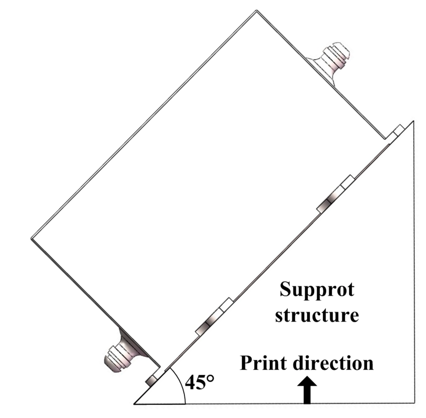
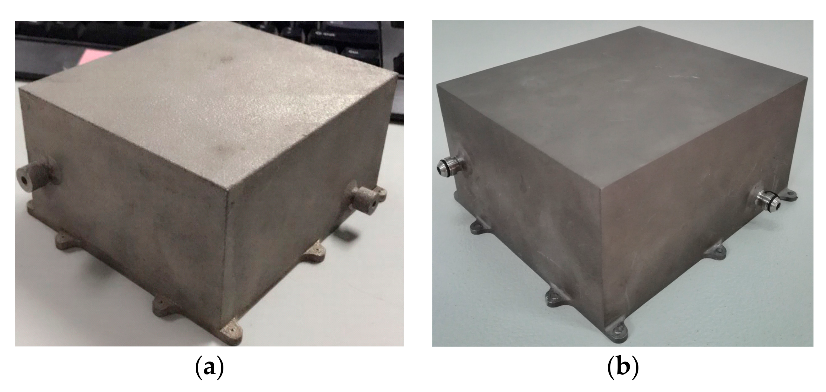
This paper presents an improved mesh storage tank structure obtained using selective laser melting (SLM) 3D metal printing. The storage tank is optimized using a multi-objective uniform design method. The parameters of the mesh structure, such as the length, three direction intervals, wall thickness, and the connecting distance to the side wall, are considered the optimization factors. The compressive stress, volume utilization ratio, and weight parameters are considered the optimization objectives. Optimization factors and targets for the storage tank are shown in
Table 1. Regression equations are established between the optimization factors and targets, the orders of the six factors affecting the three target values are analyzed, and the validity of the regression equation is verified. The values of the influence factors are obtained via optimization. The relative deviations between the regression equation and calculation results are analyzed, and the improvements for compressive stress, volume utilization ratio, and weight are discussed. The optimization results are verified via experiments; consequently, the compressive stress is improved, the utilization rate is increased, and the weight is reduced.
3. Storage Tank Performance Analysis
3.1. Mechanical Property Measurements
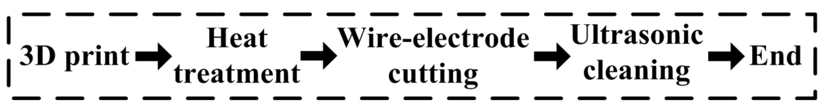
To obtain the properties of the 3D printing material, three tensile specimens are pre-printed. The size of the pre-printed tensile specimens are as follows: length of 80 mm and diameters of 20 mm and 15 mm. The related introduction for additive manufacturing and post-processing steps for pre-printed tensile specimens are show in
Table 2 and
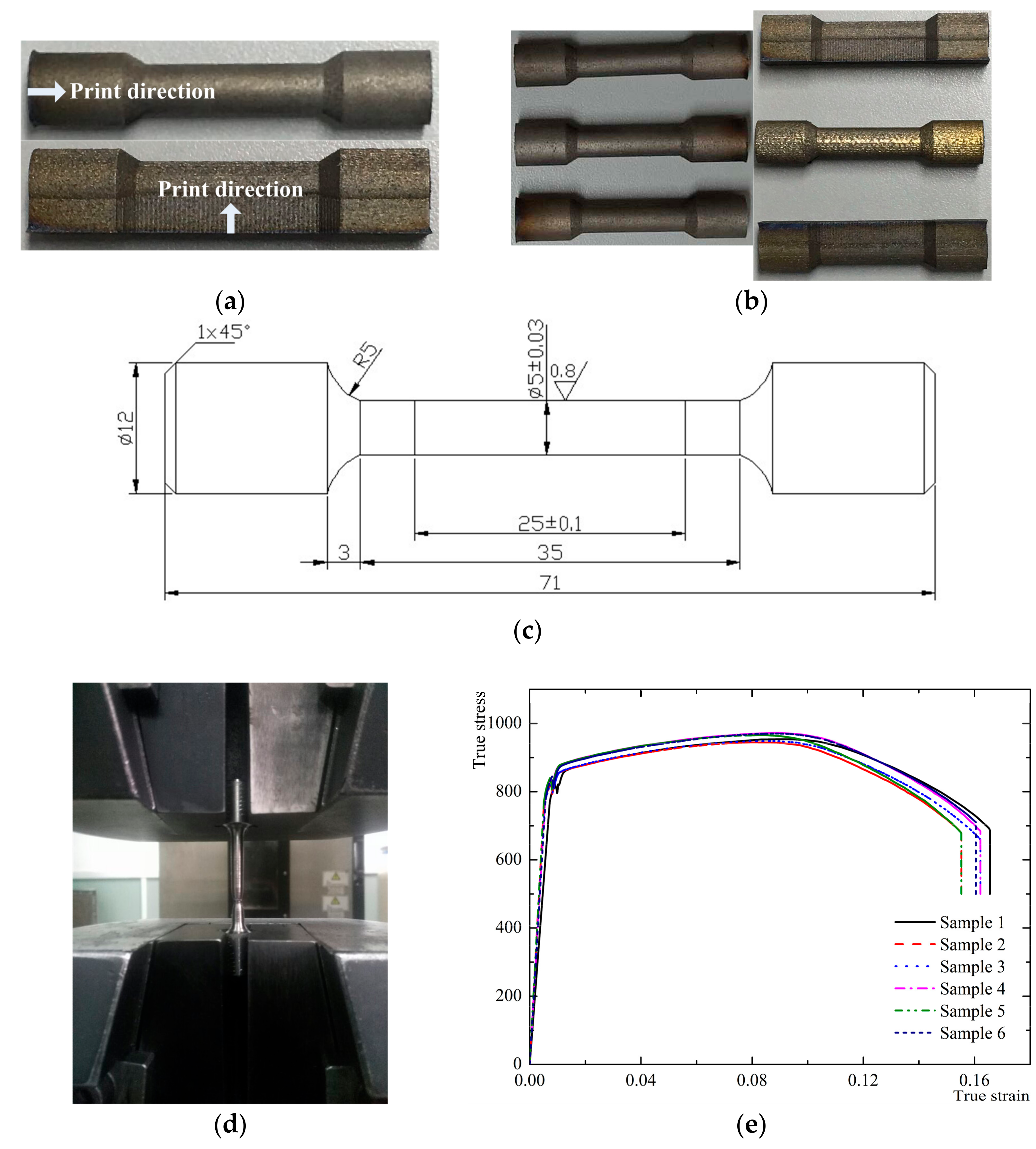
Figure 4. The dimensions of tensile specimens are selected based on the recommended dimensions of the Instron 3382 tensile testing machine (Instron, Boston, MA, USA). In
Figure 5, the print direction, 3D printing specimens, tensile specimen size, tensile test, and true stress–strain [
39] diagram of the material are shown. The final mechanical properties of the specimens are given in
Table 3.
3.2. Compressive Stress Analysis
The performance of the storage tank is mainly evaluated in terms of the compressive stress, volume utilization rate, and weight. We utilize conventional, rectangular, and improved tank structures whose envelope dimensions are: length, 112 mm; width, 130 mm; and height, 66 mm. Furthermore, a single column structure with a square or circular cross shape is used. We suppose that the length and diameter of the single column structures are both 1.5 mm, and the number of the single column structures in three directions are assumed to be 9, 17, and 19, respectively. The wall thickness is assumed to be 0.5 mm, and the connecting distance to the side wall is 5.5 mm. The wall thickness of the conventional and cuboid storage tanks are 2.1 mm and 0.5 mm.
The propulsion system is also used for the storage of the liquid ammonia container. This choice mainly helps the system withstand the internal pressure load. A system that can withstand a higher pressure of saturated ammonia steam, which can provide greater thrust to the propulsion system leading to a more stable performance.
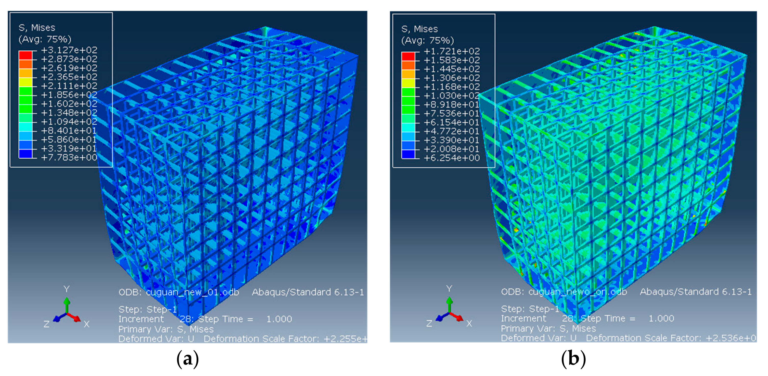
We used Solidworks design software (Dassault Systemes S.A, Concord, MA, USA, 2014) to build six kinds of 1/8 storage tank models to analyze the compressive stress. The size of each storage tank model mesh is 8 mm. In order to improve the calculation efficiency we used a large mesh size. Though the mesh size is very large, it can acquire the rough stress values of different storage tanks while not affecting the trend analysis of the stress. The boundary conditions in the three directions are the symmetry constraints and the 2.4 MPa pressure applied to the inner wall. We input the density, Young’s modulus, Poisson ratio, yield strength, and tensile strength into ABAQUS finite element software (Dassault Systemes S.A, Concord, MA, USA, 2013), which we used to directly perform static ideal elastic-plastic modelling.
The analysis results of the strength of the storage tank are shown in
Figure 6. The stresses of the four kinds of storage tanks used are 417 MPa, 1357 MPa, 1488 MPa, 2737 MPa, 214 MPa, and 122 MPa, respectively. The results show that the thinner walled storage tank can reduce mass, but it can be subject to greater stress, buckling, and rupture, as shown in
Figure 6c,d. The improved mesh structure with the square column structure can withstand a greater pressure load. Hence, we abandon the schemes of
Figure 6c,d.
3.3. Volume Utilization Rate Analysis
The higher the volume utilization ratio of the tank, the more propellant it can carry. It can prolong the life of the propulsion system and improve the control capability of the altitude and orbit of the satellite [
41]. The volume utilization rate refers to the ratio of volume of the inner liquid to the volume of the envelope. The volume utilization ratios of the four storage tanks are denoted as
,
,
, and
, and they can be expressed as:
where
is the volume utilization ratio of the conventional storage tank,
is the volume utilization ratio of the cuboid storage tank,
is the volume utilization ratio of the improved storage tank with a circular column structure, and
is the volume utilization ratio of the improved storage tank with a square column structure.
is the functional expression when the propellant forms an enclosed area
in the conventional storage tank.
is the functional expression when three cylindrical structures form a closed area
at the intersection.
The calculation results of the propellant volume and volume utilization rates of the four kinds of storage tanks are presented in
Table 4. The propellant volume and volume utilization rate of the conventional storage tank are lower than those of other types of tanks; however, there is considerable room for improvement of the conventional storage tank for carrying the propellant.
3.4. Weight Analysis
Weight reduction directly determines the performance of the product and launch cost [
42,
43] and, hence, is a major concern in the aerospace field. If the weight of the storage tank is greater for the same envelope and the effective volume occupied by the storage tank is greater, it can carry less propellant. Therefore, we must consider trade-offs when improving the strength and volume utilization rate of storage tanks.
Depending on the volume of propellant to be filled in the storage tank, the mass of the cuboid, improved storage tanks with a circular and square column structure can be expressed as:
The weights of the four storage tanks are listed in
Table 5. The results show that the conventional storage tank has a significant advantage in weight, and the improved storage tank needs to be optimized in terms of weight reduction.
4. Structural Performance Optimization of Storage Tank
According to the comparison of the three structural performances in the previous section, i.e., compressive stress, volume utilization rate, and weight, the structural performance of the conventional storage tank would be significantly improved by changing its structure. As the conventional tank is oval, the corresponding reinforcement and accessories must be increased for installation in a satellite and, hence, the weight of the conventional storage tank is increased to 600 g. The improved storage structure with square column structure can be directly installed, and the installation can reduce the weight and simplify the installation process. Through the analysis of the compressive stress, volume utilization rate, and weight of conventional storage tanks, the optimization objectives for the structural performance of improved storage tanks are determined, as presented in
Table 6. Structural performance optimization of a storage tank, the optimization equations, different variables, and constraints can be expressed as:
4.1. Optimization Method of Structural Performance
Generally, in a multi-factor test, increased numbers of factors and levels cause an exponential increase in the number of tests to be conducted. The determinant factors for the structural performance of a storage tank are length , mesh structure numbers in the three directions , , and , wall thickness , and connecting distance to the side wall . According to the characteristics of these factors, we can adopt a parametric test method. Twenty-five tests are required for six factors and four levels, whereas for six factors and six levels, 49 tests are required. However, for six factors and 11 levels, orthogonal tests cannot be created. A uniform design can solve the multi-factor and multi-level problems, and this requires fewer test combinations to obtain the influence of each factor on the target value, or even determine the value of each factor when it arrives at a satisfactory target value.
4.2. Optimization Process of Structural Performance Parameters
According to the analysis results in
Section 3, the improved storage tank with a square column structure has less compressive stress, a greater volume utilization rate, a lighter weight, and more room for improvement; therefore, we select and optimize the improved storage tank with the square column structure. Owing to the precision limit of 3D metal printing, the precision fluctuation is in the range of −0.3–0.3 mm during the process of printing. When the accuracy is limited, the fluctuation can become 0–0.2 mm. In order to prevent the optimized parameters from not printing as well as convenient optimization, we select
in the range of 0.5–1.5 mm,
,
, and
in the range of 11–21,
in the range of 0.3–0.8 mm, and
in the range of 2–7 mm.
According to the ranges of factors affecting the performance of the storage tank structure, the parameter level table is established, as presented in
Table 7. Without considering the interaction among various factors, the parameter level table of six factors and 11 levels is established. Eleven types of storage tank models are built and inputted into ABAQUS FEA software. The parameter level table, calculation, and simulation results are listed in
Table 8.
Most of the experimental design methods usually use the variance and regression analysis to process the data. The test of the uniform design is relatively small. In order to not realize the analysis of variance, the regression analysis is the main method of uniform design. If the factor level is greater than the number of test factors, two regression analyses can be used. This paper can only use multiple linear regression analysis, so the
,
, and
of the linear regression equations can be expressed as:
We want to know which factors influence the target values significantly. In order to determine the influence of each factor on the target value, we must analyze the statistic of the regression coefficient, that is,
value analysis. When the
value is lower than the significance level 0.05, indicating that the factors are related to the target value, a lower
value indicates a stronger effect on the target value. The analysis results are shown in
Table 9.
From
Table 9, we can obtain the effect of the
values of six factors on
,
, and
. The orders of the six factors affecting
,
, and
are
>
>
>
>
>
,
>
>
>
>
>
and
>
>
>
>
>
, respectively. This shows that
most strongly affects
,
, and
, and
is related to the three target values, having the strongest dependency between
and
. Moreover,
also affects
, and
is related to
. Other factors have weaker effects and dependencies on these three target values.
We use 1stOpt software to optimize
,
, and
, where the detailed optimization settings are shown in
Table 10. When
,
, and
are set to the target values, we can obtain the values of each parameter. According to the orders of the six factors affecting
,
, and
, and in order to facilitate the processing, modelling, and calculation for the final printing, the final value of each parameter is selected to be equal or greater than the optimal value of each parameter. The optimal values are listed in
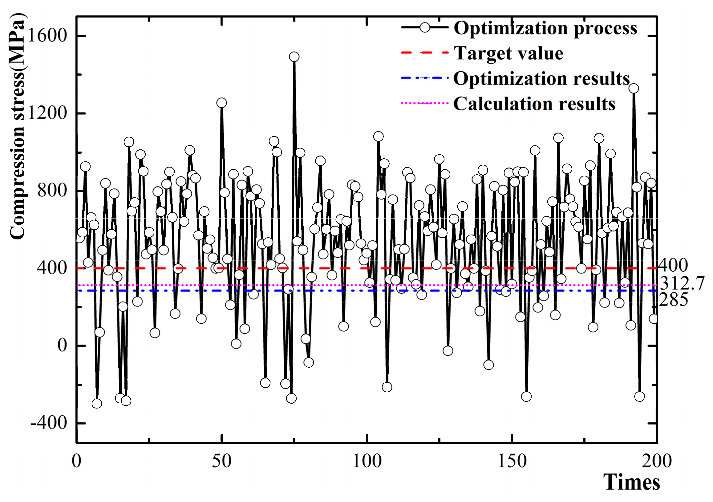
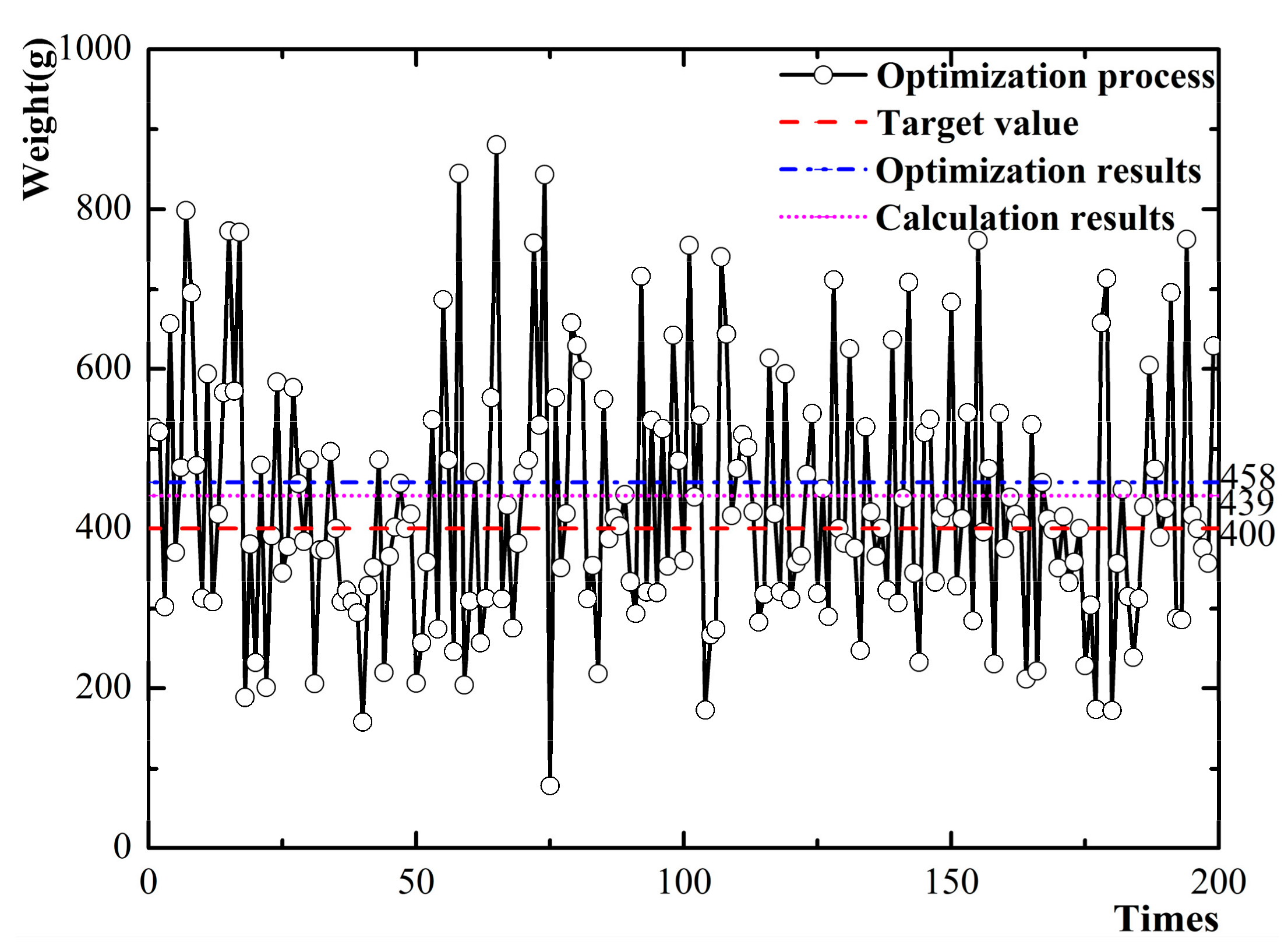
Table 11. The optimization process, optimization results, and calculation results are shown in
Figure 7,
Figure 8 and
Figure 9, respectively.
According to the analysis results, the relative deviations of compressive stress, volume utilization rate, and weight between the optimization results and calculated results are 9.72%, 2.94%, and 4.15%, respectively. It has been demonstrated that the established regression equation can predict the structural performance of the improved storage tank.


