Abstract
Machine vision systems are an important part of modern intelligent manufacturing systems, but due to their complexity, current vision systems are often customized and inefficiently developed. Generic closed-source machine vision development software is often poorly targeted. To meet the extensive needs of product appearance quality inspection in industrial production and to improve the development efficiency and reliability of such systems, this paper designs and implements a general machine vision software framework. This framework is easy to adapt to different hardware devices for secondary development, reducing the workload in generic functional modules and program architecture design, which allows developers to focus on the design and implementation of image-processing algorithms. Based on the MVP software design principles, the framework abstracts and implements the modules common to machine vision-based product appearance quality inspection systems, such as user management, inspection configuration, task management, image acquisition, database configuration, GUI, multi-threaded architecture, IO communication, etc. Using this framework and adding the secondary development of image-processing algorithms, we successfully apply the framework to the quality inspection of the surface defects of bolts.
1. Introduction
For industrial production, the inspection of product appearance quality is a crucial aspect that traditionally relies on manual inspection. High-resolution industrial cameras and increasingly sophisticated image-processing algorithms enable quality inspection with ideal detection accuracy [1] and machine vision inspection can avoid the problems caused by fatigue and the subjective factors of manual inspection.
Most machine vision research on product appearance quality inspection is dedicated to algorithm design, whereas software in industrial production includes not only inspection algorithms but also a GUI, database, IO communication, image capture [2], etc. In industrial applications, it is inefficient to repeatedly design and develop inspection system software for each specific inspection task.
Many researchers have designed and implemented some specific base platforms and software libraries based on the idea of modularity. Răileanu et al. implemented an open-source machine vision platform based on the OpenCV library for applications in vision robot guidance and automated product inspection [3]. Akcay et al. designed a deep learning anomaly detection library Anomalib [4], which provides anomaly detection components and tools based on deep learning techniques and supports plug-and-play for the model’s components. Dawkins et al. designed an open-source platform that provides common analysis and processing algorithms for underwater images and videos [5]. The platform provides a common cross-language interface for several algorithms. Prasad reviewed the general software and commercial packages available in the medical field for the analysis of the microimages of immunohistochemically stained specimens and affirmed the value of developing free software for the quantification of staining intensity [6]. Ruggieri et al. proposed a machine learning-based framework called VULMA [7]. VULMA obtained good results on the vulnerability analysis of buildings using photographs. Schindelin et al. implemented Fiji [8], an open-source software platform focused on bio-image analysis as an effective collaboration platform between computer science and biological research. The above platform systems are application-specific, whereas general-purpose machine vision platform systems for product appearance quality inspections are still relatively rare.
At present, HALCON, VisionPro, and NI Vision are the commonly used commercial vision development software [9]. HALCON is a mature standard machine vision algorithm package developed by MVtec. VisionPro is machine vision software from Cognex that provides rapid application development capabilities for drag-and-drop operations. NI Vision was designed by the NI Corporation for engineers and scientists developing machine vision and scientific imaging applications. In addition to the high commercial costs, their high versatility also means that surface detection is not targeted enough. Some requirements of the appearance quality inspection of industrial products, such as task configuration, a database, multi-thread architecture, etc., need to be implemented separately. We hope to achieve a new balance between universality and pertinence in surface defect detection.
A framework is a kind of semi-finished software with specific functions. Based on the functionality and architecture provided by the framework, developers need to develop their own software for specific business logic and requirements. Frameworks can reduce a lot of basic code-writing work, which increases the efficiency and speed of development. Vision software frameworks have been proposed by researchers in some areas, but software frameworks for product appearance quality inspections in industrial automation applications are still relatively lacking.
Wotawa et al. proposed a framework for the automatic generation of system tests based on vision and image recognition and demonstrated an industrial imaging application based on this framework [10]. However, the framework still lacks interaction with automated devices and is far from ready for industrial automation applications. Mönck et al. presented an open source framework for animal tracking that provides programmers with the core features essential for tracking software [11], such as video IO, graphics overlays, and mouse and keyboard interfaces, allowing researchers to accelerate their research. Rodríguez et al. proposed a real-time computer vision software framework that supports multi-threading and GUIs [12]. Heuss et al. introduced a skill-based software framework that allows for the flexible configuration of industrial robot functions [13], reducing the effort and time required to develop industrial robot applications.
Based on the MVP design principle, we applied the modularity concept to develop the visual product appearance quality inspection software framework. After the modular design, the visual inspection software is abstracted into several general modules. The framework supports embedded algorithms and other special modules. We think that researchers should focus on the design of schemes and quality detection algorithms in the development of practical project applications.
In practical applications, after embedding several image-processing detection algorithms, as well as deep learning detection networks, we successfully apply the framework to bolt quality inspection and part condition recognition. Our main contributions can be summarized as follows:
- (1)
- According to the idea of modularization and decoupling, a reusable general appearance quality inspection software framework is designed and implemented based on MVP.
- (2)
- According to the requirements of appearance quality inspections, the inspection task configuration and database function are designed and implemented.
- (3)
- According to the requirements of real-time detection, a multi-threaded inspection software system architecture is designed and implemented.
- (4)
- The software framework is successfully applied to the surface defect quality inspection of bolts and part condition recognition.
2. Structure of Machine Vision Software Framework
2.1. Hardware Architecture
The hardware equipment of an appearance quality inspection system generally includes the main control computer, industrial camera, vision light source, IO communication device, and alarm [14,15], as shown in Figure 1.
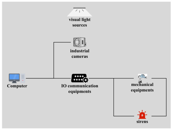
Figure 1.
Hardware composition.
The performance of the computer can be adjusted according to the task requirements. The computer is connected to automated machinery via IO communication devices. The alarm can be configured according to the task demands, whose alarm signal can be given by the computer or the automation equipment.
The industrial camera is the information acquisition device of the machine vision quality inspection software. Its imaging results directly affect the design of algorithms during image processing. Most industrial cameras are based on CCD [16] or CMOS [17,18] chips. Specific scenarios usually require the selection of the appropriate camera vendor, type, and parameters according to the inspection needs of the target product.
Visual light sources are used to highlight the subject, weaken the background, enhance features, and make the camera obtain a higher-quality image. It is necessary to choose the proper machine vision light source solution in the design of the scheme [19,20], such as a flat light source, hemispherical light source, ring light source, multiple light sources, etc.
IO communication devices are usually used for communication between the vision software host computer and electromechanical devices. Common communication methods use serial ports or network interfaces [21,22]. With the continuous development of technology, more and more protocol technologies have appeared in the field of industrial communication [23]. Considering simplicity and adequacy, serial ports and Modbus protocols are widely used for communication in industrial applications [24]. The IO modules within the software framework support the standard Modbus protocol by default.
2.2. Software Design Patterns
To improve the readability and testability of the software framework and ensure scalability and flexibility, the software framework is designed based on the MVP software design pattern.
The MVP pattern [25] is an improvement of the MVC pattern. MVC (Model-View-Controller) is a design pattern for software [26]. The MVC pattern divides the software system into three core modules: the view module, the control module, and the data model module, which correspond to the V, C, and M in MVC. The relationship between the three is shown in Figure 2.
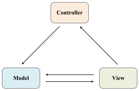
Figure 2.
MVC.
MVP is Model-View-Presenter, and Figure 3 shows the relationships within the MVP model. In MVP, the View and Model are not allowed to interact directly, whereas the Presenter must be used as a bridge and has permission to access both the Model and the View. When the View responds to an operation of the user, the corresponding interface of the Model is accessed through the Presenter, and when the data results need to be fed back to the user, the updates on the View are also made through the Presenter. Compared with MVC, MVP further reduces the coupling of code between the View and the data model.
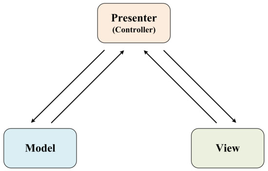
Figure 3.
MVP.
2.3. Design of the Functional Modules of the Software
According to the MVP design pattern, Figure 4 shows a brief logic diagram of the software framework. Like the mediator pattern [27], when there are multiple modules in the Model and multiple GUI interactions in the View, the system appears as a complex group of many-to-many coupled objects. The Controller not only reduces the coupling between the modules so that developers can modify and reuse each module independently but also encapsulates the abstraction of the collaboration between the class objects to focus on the interaction of module objects.
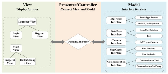
Figure 4.
Logic diagram of the framework’s design.
The View subsystem is mainly used to accept users’ input and display the processing results. The framework completes the relevant interaction logic within the corresponding functions triggered by the View functional component after receiving operations such as selection, input, and click. Configuration information and detection data need to be obtained by calling the corresponding interface through the Controller subsystem.
The Controller subsystem is mainly used for the control between the View subsystem and the Model subsystem, making the View subsystem call the camera, detection algorithm, etc., and the Model subsystem obtains the results and the data is displayed on the View in a unified and orderly management implementation. After the instruction is issued by the View subsystem, the instruction goes through the Controller to execute the corresponding data model functions. The main class “DomainController” in the Controller subsystem contains the upper layer interfaces of all modules. When modifying the UI layout, developers need to access “DomainController” to execute the corresponding function after the view component receives the click, selection, input, etc. In addition, the singleton pattern [27] is followed in the implementation of the Controller. The Controller keeps its own unique instance, which strictly controls when and how “clients” access it, reducing code coupling and improving maintainability.
The Model subsystem mainly provides the machine vision algorithm module, database control module, camera module, and communication module. Specifically, the algorithm module can be embedded with suitable algorithms according to actual needs. The database control module is mainly responsible for data storage and reading. The underlying driver for the camera module needs to be implemented by selecting the corresponding vendor’s SDK. IO communication protocols can be changed to UART, S7, and other protocols by modifying the corresponding underlying code as needed, whereas the default protocol is Modbus. The upper-layer code does not need to be changed.
Table 1 lists the main modules of the View subsystem and the Model subsystem and their functions, which are discussed in the third subsection.

Table 1.
System module functions.
2.4. Multi-Threaded Architecture of the Software
Industrial vision inspection often requires multiple types of algorithmic processing tasks. Relying on the main thread for blocking synchronous task processing is inefficient and unsuitable for pipeline scenarios with high requirements for inspection efficiency. Therefore, the design of the software framework includes a thread-pooling technique for concurrent task processing.
A thread pool is a form of concurrent multitasking [28]. A thread pool contains several work sub-threads and a task queue. The work sub-threads will take out tasks for processing in a pre-emptive manner. The main advantage of a thread pool is the higher efficiency of the system in multitasking scenarios and the decreased coupling of the code with the separation of threads and tasks.
As shown in Figure 5, the main thread, which is the thread started by the main function, is only responsible for the basic work of the GUI display, image acquisition, and IO communication. The specific image-processing task is delivered to a worker sub-thread of the thread pool for processing and the result is returned to the main thread when finished. The thread pool is constructed by initializing a number of work sub-threads equal to mMaxThreadNum and preparing a task queue. By default, mMaxThreadNum = 8. In practical application scenarios, it can be reset to a suitable number according to the demand and performance of the computer.
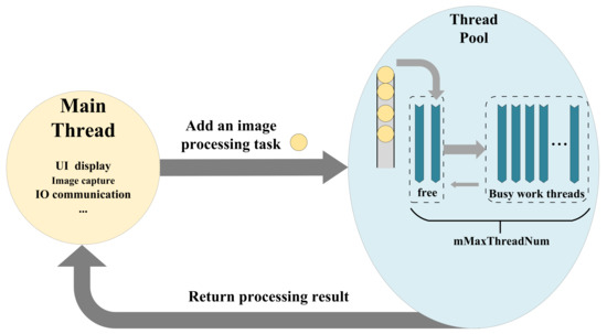
Figure 5.
Multi-threaded architecture.
The logic implemented by default within each view class includes a GUI display, jumping between multiple views and actions (selection, input, click, and other operations to call the camera or database). The operation commands and corresponding functions need to be reconnected within the view class when modifying the view. Simply, the “main” function in the main thread instantiates the view class and the software is ready for normal operation. The task-processing thread pool is constructed automatically when the detection algorithm module is loaded.
3. Detailed Design of Modules and Interfaces of the Software Framework
The software framework designed in this paper was implemented in the C++ programming language. The C++ language has the distinctive feature of being efficient, which is in line with the considerable software execution efficiency required in most product quality inspection scenarios. The GUI was based on Qt design and development [29]. The development environment was built on a Windows system with Microsoft Visual Studio. An OpenCV open-source library is normally used for image processing but other C++ libraries can also be added. The database module was developed based on MySQL version 5.5. Many small- and medium-sized development projects choose MySQL as their database due to its small size, speed, low cost, and open-source features [30].
Based on the principle of single responsibility [31], the software framework subdivides subsystem functionality into modules and uses inheritance and a combination of classes in each module, which reduces code coupling, improves readability, and reduces the difficulty of secondary development.
This section introduces the interfaces of each module and the parts that need to be replaced by the developer in the secondary development. According to the builder pattern [27], a class with the name “base” is usually declared in each module, and the core interface is declared inside the class using pure virtual functions. In secondary development, the implementation of the core interface is ensured despite the complex changes and business logic faced by the newly created object. The decoupling of the code between the interface and the implementation improves the maintainability of the code.
3.1. Database Module
The database module is mainly used to provide the software framework with an interface to access the database tables. Its main functions include creating and deleting tables and adding, deleting, replacing, and searching the data content of specified tables. This part is designed with three classes, namely conn_info, SingleBaseDataBase, and DataBaseInterface.
The conn_info class defines the address, user, password, and database name necessary to access the database.
The SingleBaseDataBase class defines the basic functions necessary to access the database, specifying the basic functions that subclasses inherited from this class must implement.
The DataBaseInterface class public is inherited from the SingleBaseDataBase class. It is responsible for providing the Controller with an interface to access the database tables. The DataBaseInterface class mainly encapsulates the implementation of a series of internal instructions for the operation of the database table. The specific function interfaces given by the DataBaseInterface class are listed in Appendix A Table A1.
In addition to the user data tables, the local database stores data tables for three types of content: inspection configuration, task management, and inspection results. For a task, the inspection results class contains only one task results table (*_results). The “*” indicates an arbitrary character and the name of the table is generated by the task number. The main relationships between the three types of data tables are shown in Figure 6.
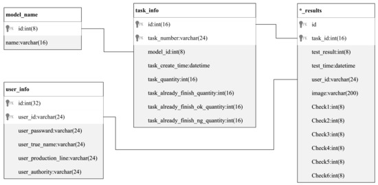
Figure 6.
Data table relationships.
The inspection configuration mainly creates a new detection data model uniquely determined by the “model_id”. The model contains a series of configurations, as described in Section 3.6. The inspection configuration class consists of five tables: the inspection configuration name table(model_name), the local marker coordinates table for storing the detection location(model_block), the marker frame-associated camera index table(camera_to_model_block_indx), the camera index-associated marker frame table(model_block_to_camera_indx), and the detection parameters table(*_setting_param). The internal relationships are shown in Figure 7.
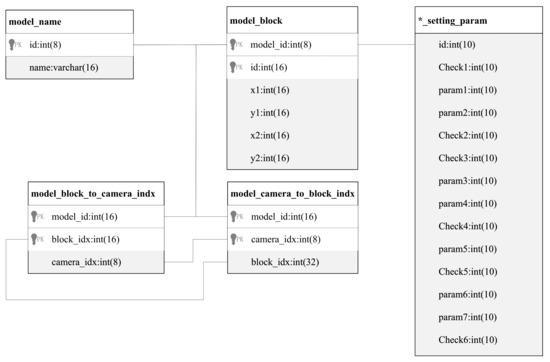
Figure 7.
Inspection configuration data table relationships.
Task management is mainly to associate the detection model with the number of users and products (the number of detections) and determine a task uniquely identified by the “task_id”, as described in Section 3.6. The task management class mainly consists of a user information table, a task information table, and a task–user association information table. The internal relationships are shown in Figure 8.
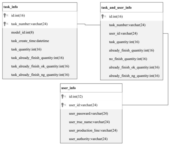
Figure 8.
Task management data table relationships.
3.2. IO Communication Module
The IO communication module is responsible for sending and receiving data between the computer program and the PLC. The main functions include the reading/writing of single or continuous register data. Four classes are designed in this part, namely CommunicationBaseTool, CommunicationTool, CommunicationToolProxy, and CommunicationToolInterface.
The CommunicationBaseTool class specifies some basic properties and functions that must be implemented by communication protocol-related driver code. All concrete implementations of communication tool classes must inherit from this class.
CommunicationTool is responsible for the implementation of the relevant driver code for a specific protocol, which needs to be re-implemented by the developer according to the actual communication protocol used. The variables required for the relevant protocol are defined as private. As an example, the functions for Modbus communication based on the libmodbus library are given in Appendix A Table A2.
CommunicationToolProxy is a proxy for CommunicationTool, which hides the actual IO communication and accesses it through a proxy. Intuitively, CommunicationToolProxy further decouples communication from the business logic of communication according to the proxy pattern [27]. Developers can re-implement the business logic according to the requirements of the implementation project, and the default functions are given in Appendix A Table A3.
The CommunicationToolInterface class gives the external communication interface for the Controller to call.
3.3. Camera Module
The camera module is responsible for providing the driver code for the software framework camera including the camera settings and image-capturing functions. Three classes are designed for this part, namely SingleBaseCamera, SingleSoftTrigglerCamera, and CamerasInterface.
The SingleBaseCamera class specifies some basic properties that every camera must implement. All camera device classes need to inherit from this class.
The SingleSoftTrigglerCamera class inherits from the SingleBaseCamera class and configures handles, image buffers, etc., for each camera device. Some functions of the SingleSoftTrigglerCamera class need to be re-implemented according to the SDK provided by the camera manufacturer (see Appendix A Table A4).
The CamerasInterface class is responsible for providing the Controller with an interface to access the camera driver. The function interfaces of CamerasInterface are listed in Appendix A Table A5.
3.4. Detection Algorithm Module
There are two types of algorithms in the algorithm module section. One is the testing algorithm during the detection configuration and the pre-extraction of some parameters or templates; the other is the real-time detection algorithm repeatedly called by the software. Three classes are designed for this part, namely DetectTypeProcess, DetectTypeRegulation, and AlgorithmInterface.
The DetectTypeProcess class is used for the implementation of specific image-processing algorithms. The specific functions that need to be re-implemented are given in Appendix A Table A6. In the absence of datasets or for relatively simple defect detection, professionals can directly design image-processing algorithms and implement them based on OpenCV. Using libtorch to deploy the deep learning model trained by pytorch is also a suitable method for complex defect detection when the dataset can be made. Thanks to the C++ deployment of libtorch, we can use YOLO, R-CNN, MobileNet, RseNet, etc. The only thing we need to pay attention to is the computer hardware support and the time cost of running the network.
The DetectTypeRegulation class is responsible for setting the number of types to be detected during the detection process and the parameters to be preprocessed. The parameters can be changed if necessary. The DetectTypeRegulation class corresponds to the context object in the strategy pattern [27], which separates the implementation and usage options for each type of algorithm and invokes all algorithms in a unified way. In unit testing, the strategy pattern also allows the system to be tested separately through the algorithm’s interface. These reduce the coupling of the code.
The AlgorithmInterface class inherits publicly from the DetectTypeRegulation class and is responsible for providing the Controller with an interface to access specific algorithms. The function interfaces of AlgorithmInterface are shown in Appendix A Table A7.
3.5. User Management
As shown in Figure 9, the system users are divided into four permission levels: super administrator, system administrator, technical staff, and common staff.
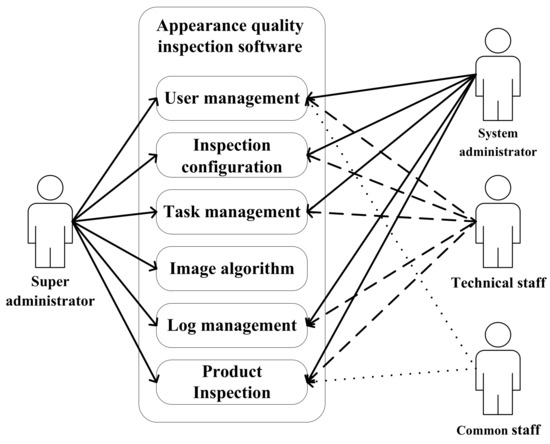
Figure 9.
User permissions.
3.6. Inspection Configuration and Task Management
3.6.1. Inspection Configuration
The purpose of the inspection configuration is to create a new detection data model uniquely identified by the “model_id”. A detection model can contain multiple camera images and multiple detection requirements, which are achieved in parallel by a thread pool. The specific configuration includes the identification of the detection camera, the labeling of the detection location in the camera image, the enabling or disabling of multiple detection functions, and the setting of the detection parameters.
The inspection configuration is mainly done in the “image set” View of the framework, as shown in Figure 10. After selecting the camera corresponding to the image to be detected, a rectangular box is used to mark the ROI. Then, the appropriate detection algorithm is selected for this ROI with the pre-inputted parameters. One or more detection algorithms can be selected for an ROI. The detection data section shows the specific configuration algorithm, as well as the parameters, with a 1 in the algorithm column indicating enabled and a 0 indicating disabled. The configuration information stored in the database is similar.
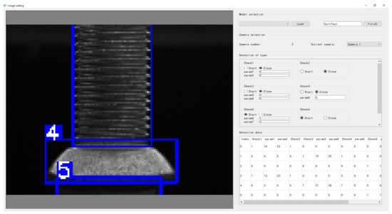
Figure 10.
New model creation.
The inspection configuration information is stored in the database. The coordinates of the ROI are stored in the table “model_block” (see Appendix A Table A8 for an example). The association between the camera and the ROI marker box is stored in the tables “model_block_to_camera_indx” and “model_camera_to_block_indx”, and the model’s name and unique id are stored in “model_name”, as described in Appendix A Table A9, Table A10 and Table A11. The configuration information of the detection algorithm for the ROI is stored in a new table, the name of which is generated based on the entered model name. An example “bolttest_setting_param” is shown in Appendix A Table A12.
3.6.2. Task Management
Task management is to determine a task uniquely identified by the “task_id” by associating the detection model with the users and the number of products (number of inspections). Before creating a task, the corresponding inspection configuration needs to be completed and the user account with the corresponding authority needs to be created.
Multiple task configuration information can be stored in the database, but only one task can be selected for execution at a time. The operation stores the assignment of tasks to common staff accounts in the database table “task_and_user_info” and the main information about the task in “task_info”, as described in Appendix A Table A13 and Table A14.
4. A Framework Application—Bolt Defect Inspection
Based on the software framework of this paper, we constructed a quality inspection system for bolt surface defects. In this application, three HIKROBOT cameras, MV-CE050-30UM, and one HIKROBOT camera, MV-CE050-31GM, were used. The system detected several defects such as thread damage, surface soiling, inner-hole soiling, etc., as well as calculated and measured the thread length and pitch. The three cameras were placed at 120° intervals to ensure that the entire outer surface of the bolt was photographed for inspection. For better imaging, a hemispherical blue light source was installed above the bolt to eliminate shadow interference as much as possible. The side view of the bolt is shown in Figure 11. A single camera was used to photograph the bore of the bolt to detect fouling. For better imaging, a coaxial light source was added to use parallel light irradiation. The bore image is shown in Figure 12.
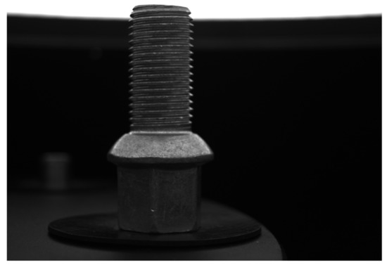
Figure 11.
Bolt side.
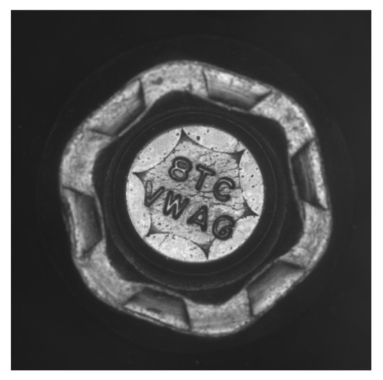
Figure 12.
Bolt bore.
As shown in Figure 13, the wavelet transform was used for the thread part of the damage detection. The results of the wavelet transform were used to detect the bright spots to determine whether they were damaged or not. The Haar wavelet was used to decompose the image and the column wavelet transform showed the contour information of the thread, which had little value for detection, so the column transform wavelet transform was discarded. As seen in Figure 14, the effect of the superposition of the three-level wavelet row transform and three-level wavelet diagonal transform showed that the wavelet response in the defective part was obvious. After binarization, the maximum white area was found. If the area was greater than a given threshold, it was considered thread damage.
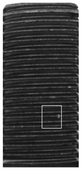
Figure 13.
Thread bruises.
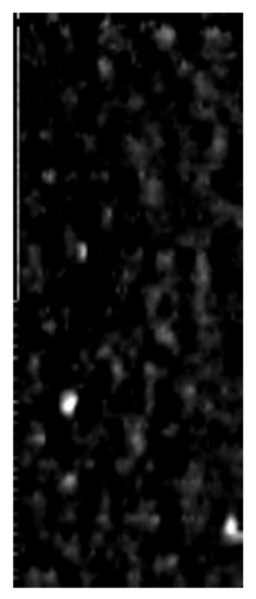
Figure 14.
Wavelet transform.
As shown in Figure 15, low-pass filtering was used for the thread portion of the dirty thread detection. A sliding window was used to calculate the relative grayscale mean of the low-pass filtering results to determine if they were dirty. The image was subjected to a column DCT transformation and the high-frequency part was filtered out (N = 1000, 0–32 was retained). As shown in Figure 16, it is clear that the gray value of the left dirty part is lower than the gray value of its neighborhood. A sliding window of 40 × 40 was used to check the gray value in the window. When the difference from the average value was below the threshold, dirt was detected.
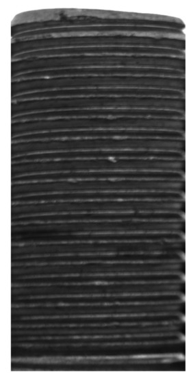
Figure 15.
Dirty thread.
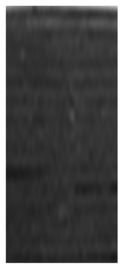
Figure 16.
DCT filtering results.
As shown in Figure 17 and Figure 18, the two types of defects, bolt head damage and defects in the sphere, had various forms. So, a deep-learning model was used to detect whether the bolt was defective or not. “Defects in the sphere” refers to scratches, dirt, or poor plating on the spherical surface of the ring below the threads. “Bolt head damage” refers to the presence of scratches, dirt, or poor plating on the six planes or six ribs below the sphere.
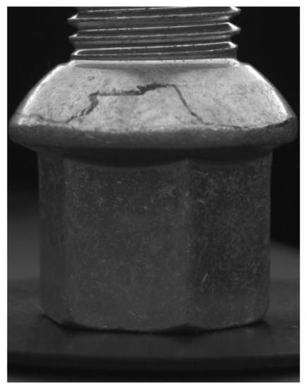
Figure 17.
Defects in the sphere.
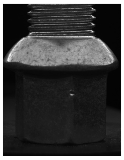
Figure 18.
Bolt head damage.
The thread length was measured by the change in the average gray level of the rows. The thread pitch was measured by cropping the thread boundary and projecting it onto the line. To calculate the thread pitch, the boundary area of the thread should be trimmed and its gray value should be projected onto the edge line. After the DCT transformation (N = 1000) was performed on the projection results, the principal frequency was obtained and the pixel pitch of the threads was determined. In addition, because the low-frequency signal was large but the frequency corresponding to the thread pitch could not be so low, the low-frequency component of the projection sequence was filtered out by the first-order difference before the DCT transformation. Figure 19 shows the region of interest at the thread edge. As can be seen in Figure 20, the main frequency is at k = 34, then the pixel spacing is 2000/34 = 58.8.
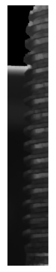
Figure 19.
Thread cut.
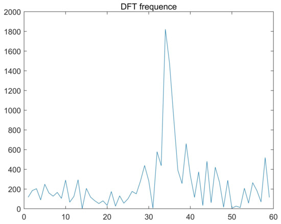
Figure 20.
DCT Frequency.
As shown in Figure 21, the bore gap used the connectivity of the region to detect whether the circle at the bottom of the bore was connected to the bore wall by a gap. Normally, the grain of the inner hexagon should not be connected to the outside. We took out the outer ring image and used corrosion and expansion for morphological processing. Finally, the flooding algorithm checked whether the inner and outer rings were connected.

Figure 21.
Bore gap.
As seen in Figure 22, the absence of letters in the bore was also detected by the YOLOv4 neural network. For the setting of the YOLOv4 training parameters, the input image was resized to 128 × 128, the optimizer used was Adam, the learning rate was set to 0.001, and the epoch was set to 300. The dataset included 285 side images and 272 inner-hole images and was completed by LabelImg annotation. The data enhancement methods included brightness adjustment (brightness adjustment to 80–150% of the original image), Gaussian noise addition (Gaussian factor 0 3.0), scaling (80–105% of the original image), and rotation (−10 to 10 degrees around the image center). The training set and test set were divided by 9:1. Figure 23 and Figure 24 show the partial test results of the inner hole and the side, respectively. Table 2 shows the results for the test set. In addition, to ensure that the letters in the input image remained basically horizontal, the letter image in the inner hole was rotated by Radon transform after edge extraction before input. The letter orientation was kept positive by the difference in the width of the letter contour between the upper and lower lines.
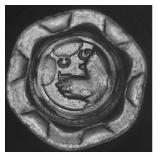
Figure 22.
Missing letters.
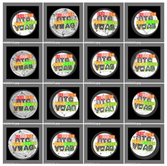
Figure 23.
Letter detection in the inner hole.
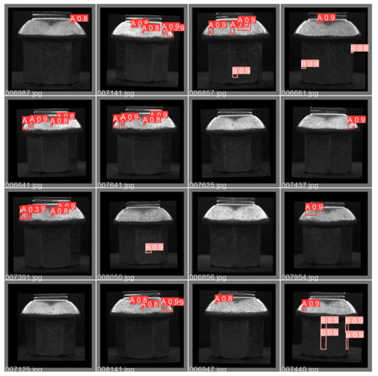
Figure 24.
Side-defect detection.
Table 2.
Side-defect and internal control letter-detection results.
As shown in Figure 25, the inner hole was determined to be soiled by averaging the gray level of the area outside the letter. For another type of soiling with a small and scattered percentage, the soiling was determined by detecting the number of small contours after a morphological top-hat operation for the area other than the letters.
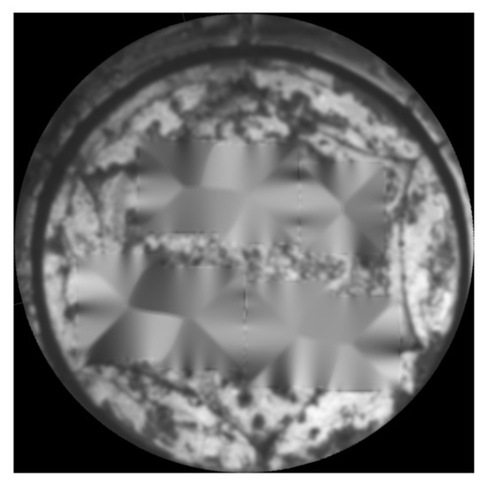
Figure 25.
Dirty bore.
In the inspection task, nine detection subtasks for the four camera images were executed concurrently through the thread pool. In this scenario, the detection time for each bolt must not exceed 1000 ms. We chose an i7-9700 computer with 4G RAM for the project, which can have good real-time performance and guarantee accuracy. Table 3 gives the times for the side-camera and bore-hole camera tasks, which were both less than 1000 ms. Because the input picture of a neural network has low resolution, the GPU was not used. In fact, we tried to use the GPU, but since the data copying between the video memory and the RAM was small but frequent, the computing speed barely improved.
Table 3.
Time cost of product quality inspection of bolts.
The detection accuracy mainly depends on the detection algorithm. Better algorithms embedded in the framework can achieve higher accuracy. The accuracy results obtained by our algorithm for 100 images of each defect detection type are shown in Table 4. The system is stable, and there will be no need to restart the industrial computer under normal working conditions because of software problems. The software can work continuously for 24 h and the number of failures is no more than one per week. The GUI of bolt quality inspection was partially modified according to the actual requirements, as shown in Figure 26.
Table 4.
Test results of bolt surface defects.
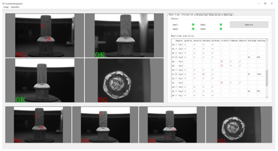
Figure 26.
Bolt inspection view.
5. A Framework Application—Part Condition Recognition
Based on the software framework of this paper, we constructed a part direction recognition system. The robot arm drives the HIKROBOT MV-CE060-10UM camera to move and shoot the parts placed in different positions on the tray. Figure 27 shows the original image of one shoot. The pictures taken at different positions were rotated to the corresponding fixed angles and trimmed to obtain a single part. The pretrained ResNet18 was used to determine the direction or a particular state of the part at a single hole. Figure 28, Figure 29, Figure 30 and Figure 31 show four examples of directions to the left, directions to the right, no part in the hole, and misplaced parts, respectively.
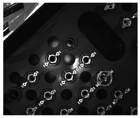
Figure 27.
Original image of one shot.
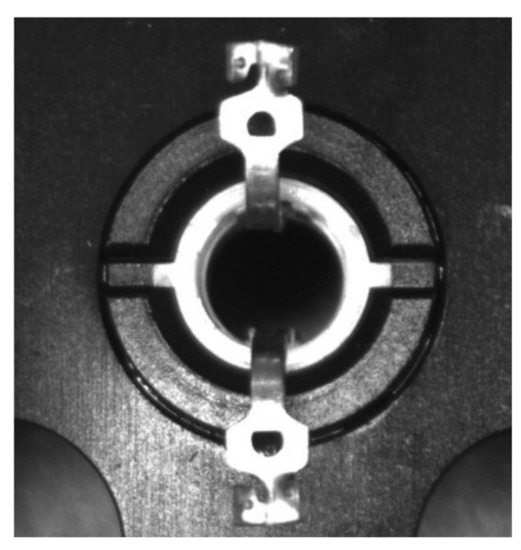
Figure 28.
Left part.
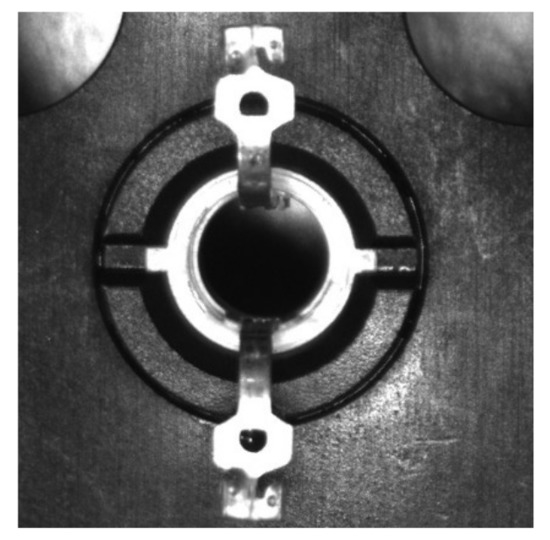
Figure 29.
Right part.
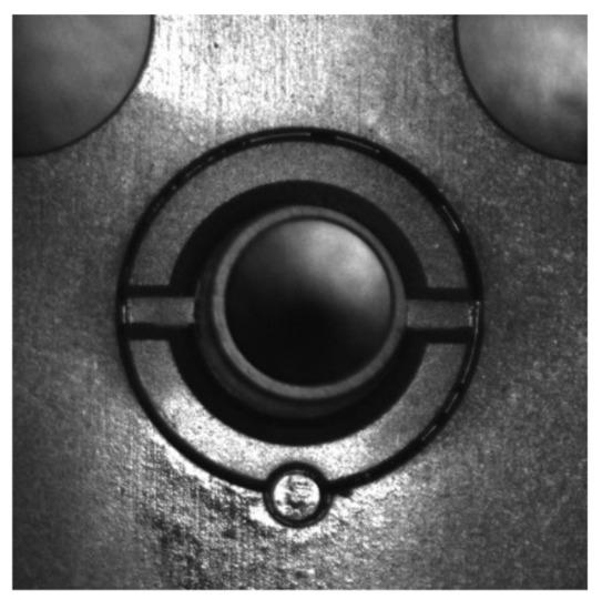
Figure 30.
No part.
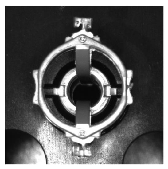
Figure 31.
Wrong part.
In the application, the PLC and the host computer used the Modbus protocol to complete the communication and the PLC sent the photo signal after the camera was in place. After the photo was taken, the signal at the end of the photo was returned and the robot arm started to move to the next position. At the same time, the image was loaded into the task queue. Part state determination was performed concurrently through the thread pool. After the 12 positions were photographed, the PLC only needed to wait for the processing time of a single picture and the status of all parts was given. Obviously, this application is much simpler than bolt detection, but the GUI, communication, camera, database module, and thread pool are still needed. Instead of repeating the development according to the business logic, our framework only needed to add the rotation of the image and deployment of Resnet18.
Specifically, we cut out the parts of the two contact positions of the part, as shown in Figure 32, Figure 33, Figure 34 and Figure 35 (the lower side is flipped to make it consistent). Each part was judged twice. We used ResNet18 to complete the judgment after OpenCV rotated and cropped the image and adjusted the size to 64*64. For ResNet18 training, the optimizer used Adam, the learning rate was set to 2 × 10, and the data enhancement modes were brightness offset, contrast offset, hue offset (random maximum offset was set to 0.5), and Gaussian blur (kernel size was 11, sigma was 0.1–3.0). The number of iterations was set to 120.
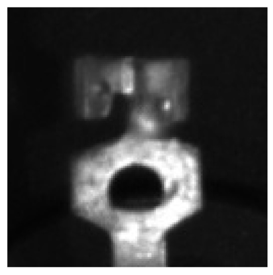
Figure 32.
Left ROI.
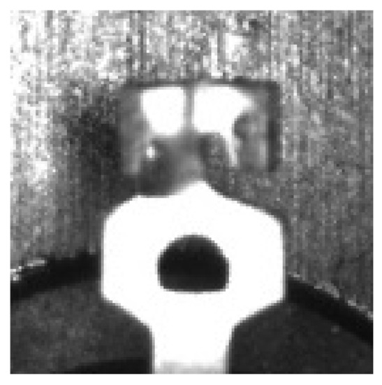
Figure 33.
Right ROI.
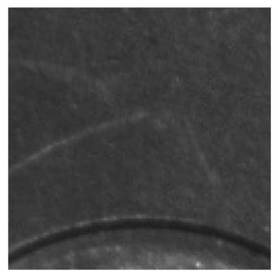
Figure 34.
No ROI.
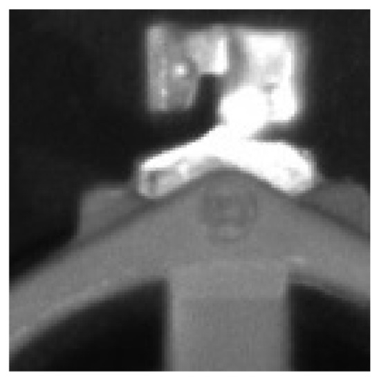
Figure 35.
Wrong ROI.
We collected and marked 2072 left-facing part pictures, 2072 right-facing part pictures, 1368 missing part pictures, and 456 wrong part pictures. We divided the training set and test set by 8:2. The accuracy of the test set reached 99.982%. The single reasoning cost of the model was 0.07364 s on a computer with an i5-10400 CPU and 16GB RAM. Each part needed to be cut and reasoned twice, taking less than 200 ms in total. Based on the model in this paper, the network model trained by libtorch was deployed, which reduced the business logic development task of appearance quality inspection and provided great convenience for the industrial vision system to quickly complete the part state judgment.
6. Conclusions and Future Research
This paper designs and implements a generic computer vision-based software framework for the use of common equipment in the inspection of the appearance quality of products in industrial manufacturing. In the development of inspection tasks for industrial manufacturing, the system can reduce the coding workload of researchers developing this type of software and they can focus on algorithms and solutions. The software framework is built according to the MVP design pattern, which makes the overall coupling of the code low. It is convenient for developers to adapt to different hardware devices for secondary development, and the thread pool designed based on tasks effectively improves the efficiency of image-processing algorithms. In specific application scenarios, we have demonstrated the rapid development capability and stability of a general-purpose vision-based software framework with a bolt defect inspection project and a part condition judgment.
In future research work, the GUI interactivity can be improved and enhanced and different basic view types can be preprogrammed for different task requirements. As a general-purpose machine vision-based inspection software framework, preconfiguring more communication protocols and basic image-processing algorithms for secondary developers is an important optimization aspect. Further decoupling the code and providing a library of functions for secondary developers to use will be the focus of our future research.
Author Contributions
Conceptualization, Q.Z, Y.Z. and J.L.; methodology, Q.Z.; software, Q.Z., Y.Z., J.L. and L.H.; validation, Q.Z., Y.Z. and L.H.; formal analysis, Q.Z.; investigation, Q.Z.; resources, Q.Z.; data curation, Q.Z.; writing—original draft preparation, Q.Z. and Y.Z.; writing—review and editing, Q.Z.; visualization, Q.Z.; supervision, Q.Z.; project administration, Q.Z.; funding acquisition, Q.Z. All authors have read and agreed to the published version of the manuscript.
Funding
This research received no external funding.
Institutional Review Board Statement
Not applicable.
Informed Consent Statement
Not applicable.
Data Availability Statement
No new data were created or analyzed in this study. Data sharing is not applicable to this article. However, the code presented in this study is available on request from the corresponding author.
Conflicts of Interest
The authors declare no conflict of interest.
Sample Availability
Samples of the code are available from the authors.
Abbreviations
The following abbreviations are used in this manuscript:
| MDPI | Multidisciplinary Digital Publishing Institute |
| MVP | Model-View-Presenter |
| GUI | Graphical User Interface |
| IO | Input/Output |
| MFC | Microsoft Foundation Classes |
| CCD | charge-coupled device |
| CMOS | Complementary Metal Oxide Semiconductor |
| MVC | Model-View-Controller |
| SDK | Software Development Kit |
| UART | Universal Asynchronous Receiver/Transmitter |
| S7 | S7 Communication |
| PLC | Programmable Logic Controller |
| ROI | Region of Interest |
| DCT | Discrete Cosine Transform |
| CPU | Central Processing Unit |
Appendix A
Table A1.
DataBaseInterface class.
Table A1.
DataBaseInterface class.
| Function | Description |
|---|---|
| void insertSingleRowData (const char *table, std::vector<std::string> &data); | Insert a row of data into the specified table. |
| void insertSingleRowData (const char *table, std::vector<std::string> &data); | Delete all data in the specified table. |
| void deleteAndReplaceNewData (const char *table, std::vector<std::vector<std::string>> &data); | Delete all data in the specified table and re-write the data as a replacement. |
| void deleteAndReplaceSatisfiedNewData (const char *table, std::vector<std::vector<std::string>> &data, const char *factorColName, std::string &factorColValue, bool isNeedQuotationMarks = false); | Delete the eligible data in the specified table and re-write the data as a replacement. |
| void deleteAndReplaceSatisfiedNewData (const char *table, std::vector<std::vector<std::string>> &data, onst char *factorColName, int &factorColValue); | Delete the eligible data in the specified table and re-write the data as a replacement. |
| std::vector<std::vector<std::string>> queryAllData (const char * table, const int colNum); | Retrieve the first “colNum” column data of all data in the specified table. |
| void createTargetTable (const char *tableName, std::vector<std::string> &colName); | Create a table, with the table name and column names determined by the parameters. |
| void deleteTabel (const char *table); | Delete the specified table. |
| bool findTargetTable (const char *table); | Query whether the specified table exists in the current database. |
| int findColNumsFromTargetTable (const char *table); | Query the number of columns of data in the specified table. |
| int findRowNumsFromTargetTable (const char *table); | Query the number of rows of data in the specified table. |
| std::vector<std::vector<std::string>> queryAllData (const char * table, const int colNum, onst char *factorColName, std::string factorColValue, const char *orderColNum = “id”, bool isNeedQuotationMarks = false); | Query the data in the specified table and return the data that match the conditions. |
| std::vector<std::vector<std::string>> queryAllData (const char * table, const int colNum, const char *orderColNum); | Query the data in the specified table and return the data that match the conditions. |
Table A2.
Functions to be reimplemented inside the CommunicationTool class.
Table A2.
Functions to be reimplemented inside the CommunicationTool class.
| Function | Description |
|---|---|
| bool init (); | The relevant initialization necessary for specific protocols. |
| bool close (); | End operations necessary for specific protocols. |
| void writeUnitToClient (unsigned int Client, unsigned int addr, transmissionUnit value); | Send single communication unit data. |
| void writeContinueUnitToClient(unsigned int Client, unsigned int addr, int length, transmissionUnit* value); | Send “length” unit data continuously. |
| void readFromClient (unsigned int Client, unsigned int addr, int length, transmissionUnit* data); | Receive “length” units data starting from “addr” of the lower computer. |
| void readWithWrite (unsigned int Client, int writeAddr, int writeLength, transmissionUnit* wtiteData, int readAddr, int readLength, transmissionUnit* readData); | Send “length” unit data continuously, and receive “readLength” unit data from the lower computer starting from “readAddr”. |
Table A3.
Functions to be reimplemented within the CommunicationToolProxy class.
Table A3.
Functions to be reimplemented within the CommunicationToolProxy class.
| Function | Description |
|---|---|
| void setCameraGrabFinishSignal (int mCameraIndex); | Send camera capture completion signal to the lower computer. |
| bool close (); | End operations necessary for specific protocols. |
| void setCameraResultSignal(int mCameraIndex, int mResult); | Send the processing result of the picture to the lower computer. |
| bool getCameraTriggerSignal(); | Read the trigger signal sent by the lower computer. |
Table A4.
Functions within the SingleSoftTrigglerCamera class that need to be re-implemented using the camera SDK.
Table A4.
Functions within the SingleSoftTrigglerCamera class that need to be re-implemented using the camera SDK.
| Function | Description |
|---|---|
| bool getSingleImage (cv::Mat & singleMat); | Take a single picture. |
| cv::Size getCameraSize (); | Return camera image size. |
| bool init (); | Required initialization operations for the camera. |
| bool close (); | Required camera shutdown operations. |
| bool PrintDeviceInfo (); | Print camera-related information. |
| bool Convert2Mat (cv::Mat & srcImg); | Convert the image storage supported by the SDK to the OpenCV library cv::Mat form and return. |
| int RGB2BGR (unsigned char* pRgbData, unsigned int nWidth, unsigned int nHeight); | Converting RGB images to BGR images. |
Table A5.
CamerasInterface class.
Table A5.
CamerasInterface class.
| Function | Description |
|---|---|
| int getCameraNums (void); | Get the number of cameras currently connected to the system. |
| cv::Size getCameraSize (int cameraIdx); | Get the captured image size of the specified camera. |
| bool getSingleImage (int cameraIdx, cv::Mat &singleMat); | Command the specified camera to take pictures. |
Table A6.
Functions to be reimplemented within the DetectTypeProcess class.
Table A6.
Functions to be reimplemented within the DetectTypeProcess class.
| Function | Description |
|---|---|
| void Check1TestSettingPreprocess1 (cv::Mat &src); | Preprocessing or algorithm testing required in the detection configuration. |
| int Check1TestSettingPreProcess2 (cv::Mat &src); | |
| bool Check1TestRegularRunningProcess (cv::Mat &src); | Detection algorithms that run in real time. Each function can perform a different task. |
| bool Check2TestRegularRunningProcess (cv::Mat &src); | |
| bool Check3TestRegularRunningProcess (cv::Mat &src); | |
| bool Check4TestRegularRunningProcess (cv::Mat &src); | |
| bool Check5TestRegularRunningProcess (cv::Mat &src); | |
| bool Check6TestRegularRunningProcess (cv::Mat &src); |
Table A7.
AlgorithmInterface class.
Table A7.
AlgorithmInterface class.
| Function | Description |
|---|---|
| void Check1TestSettingPreprocess1 (cv::Mat &src); | Call the corresponding function of the same name within the DetectTypeProcess class. |
| int Check1TestSettingPreProcess2 (cv::Mat &src); | |
| std::vector<bool> taskRun (std::vector<cv::Mat> &camerasMat, std::map<int, std::vector<int>> &mCameraParamIndex, std::map<int, int> &mBlockToCameraIndex, std::vector<std::vector<int>> &mBlockParam, std::vector<std::vector<int>> &mSettingParam); | Detection performed in real time. Based on the preconfiguration so that the corresponding camera image calls the execution of the custom image-processing algorithm function within the DetectTypeProcess class. |
Table A8.
Model_block.
Table A8.
Model_block.
| model_id | id | x1 | y1 | x2 | y2 |
|---|---|---|---|---|---|
| 0 | 5 | 753 | 1232 | 1347 | 1750 |
| 0 | 4 | 688 | 1019 | 1436 | 1262 |
| 0 | 3 | 843 | 162 | 1291 | 1055 |
| 0 | 2 | 750 | 1239 | 1339 | 1740 |
| 0 | 1 | 679 | 1017 | 1443 | 1265 |
| 0 | 0 | 841 | 158 | 1287 | 1065 |
Table A9.
Model_block_to_camera_indx.
Table A9.
Model_block_to_camera_indx.
| Model_id | Block_idx | Camera_idx |
|---|---|---|
| 0 | 5 | 1 |
| 0 | 4 | 1 |
| 0 | 3 | 1 |
| 0 | 2 | 0 |
| 0 | 1 | 0 |
| 0 | 0 | 0 |
Table A10.
Model_camera_to_block_indx.
Table A10.
Model_camera_to_block_indx.
| Model_id | Camera_idx | block_idx |
|---|---|---|
| 0 | 1 | #3#4#5# |
| 0 | 0 | #0#1#2# |
Table A11.
Model_name.
Table A11.
Model_name.
| id | Name |
|---|---|
| 0 | boltTest |
Table A12.
Bolttest_setting_param.
Table A12.
Bolttest_setting_param.
| id | Check1 | param1 | param2 | Check2 | Check3 | param3 | param4 | Check4 | param5 |
|---|---|---|---|---|---|---|---|---|---|
| 0 | 1 | 14 | 23 | 1 | 0 | 0 | 0 | 0 | 0 |
| 1 | 0 | 0 | 0 | 0 | 1 | 19 | 29 | 1 | 0 |
| 2 | 0 | 0 | 0 | 0 | 0 | 0 | 0 | 0 | 0 |
| 3 | 1 | 13 | 23 | 1 | 0 | 0 | 0 | 0 | 0 |
| 4 | 0 | 0 | 0 | 0 | 1 | 21 | 28 | 1 | 0 |
| 5 | 0 | 0 | 0 | 0 | 0 | 0 | 0 | 0 | 0 |
Table A13.
Task_and_user_info.
Table A13.
Task_and_user_info.
| id | Task_Number | User_id | Task_ Quantity | Already_ Finish_ Quantity | No_Finish_ Quantity | Already_ ok_ Quantity | Already_ ng_ Quantity |
|---|---|---|---|---|---|---|---|
| 1 | o20220503 | u21721337 | 500 | 0 | 500 | 0 | 0 |
| 0 | o20220503 | u21721331 | 500 | 0 | 500 | 0 | 0 |
Table A14.
Taskr_info.
Table A14.
Taskr_info.
| id | Task_Number | Task_Create_ Time | Task_ Quantity | Task_ Already_ Finish_ Quantity | Task_ Already_ Finish_ok_ Quantity | Task_ Already_ Finish_ng_ Quantity | Model_id |
|---|---|---|---|---|---|---|---|
| 0 | o20220503 | 2022/6/6 21:03 | 1000 | 0 | 0 | 0 | 0 |
References
- Zhang, X.; Zhang, J.; Ma, M.; Chen, Z.; Yue, S.; He, T.; Xu, X. A high precision quality inspection system for steel bars based on machine vision. Sensors 2018, 18, 2732. [Google Scholar] [CrossRef] [PubMed]
- Vogel-Heuser, B.; Diedrich, C.; Fay, A.; Jeschke, S.; Kowalewski, S.; Wollschlaeger, M. Challenges for software engineering in automation. J. Softw. Eng. Appl. 2014, 7, 440–451. [Google Scholar] [CrossRef]
- Răileanu, S.; Borangiu, T.; Anton, F.; Anton, S. Open source machine vision platform for manufacturing and robotics. IFAC-PapersOnLine 2021, 54, 522–527. [Google Scholar] [CrossRef]
- Akcay, S.; Ameln, D.; Vaidya, A.; Lakshmanan, B.; Ahuja, N.; Genc, U. Anomalib: A Deep Learning Library for Anomaly Detection. arXiv 2022, arXiv:2202.08341. [Google Scholar]
- Dawkins, M.; Sherrill, L.; Fieldhouse, K.; Hoogs, A.; Richards, B.; Zhang, D.; Prasad, L.; Williams, K.; Lauffenburger, N.; Wang, G. An open-source platform for underwater image and video analytics. In Proceedings of the 2017 IEEE Winter Conference on Applications of Computer Vision (WACV), Santa Rosa, CA, USA, 24–31 March 2017; pp. 898–906. [Google Scholar] [CrossRef]
- Prasad, K.; Prabhu, G.K. Image analysis tools for evaluation of microscopic views of immunohistochemically stained specimen in medical research–a review. J. Med. Syst. 2012, 36, 2621–2631. [Google Scholar] [CrossRef] [PubMed]
- Ruggieri, S.; Cardellicchio, A.; Leggieri, V.; Uva, G. Machine-learning based vulnerability analysis of existing buildings. Autom. Constr. 2021, 132, 103936. [Google Scholar] [CrossRef]
- Schindelin, J.; Arganda-Carreras, I.; Frise, E.; Kaynig, V.; Longair, M.; Pietzsch, T.; Preibisch, S.; Rueden, C.; Saalfeld, S.; Schmid, B.; et al. Fiji: An open-source platform for biological-image analysis. Nat. Methods 2012, 9, 676–682. [Google Scholar] [CrossRef] [PubMed]
- Wang, T.; Luo, F. Positioning control system based on computer vision. In Proceedings of the 2016 2nd International Conference on Control, Automation and Robotics (ICCAR), Hong Kong, China, 28–30 April 2016; pp. 108–111. [Google Scholar] [CrossRef]
- Wotawa, F.; Klampfl, L.; Jahaj, L. A framework for the automation of testing computer vision systems. In Proceedings of the 2021 IEEE/ACM International Conference on Automation of Software Test (AST), Madrid, Spain, 20–21 May 2021; pp. 121–124. [Google Scholar] [CrossRef]
- Mönck, H.J.; Jörg, A.; von Falkenhausen, T.; Tanke, J.; Wild, B.; Dormagen, D.; Piotrowski, J.; Winklmayr, C.; Bierbach, D.; Landgraf, T. BioTracker: An open-source computer vision framework for visual animal tracking. arXiv 2018, arXiv:1803.07985. [Google Scholar]
- Rodríguez, A.L.; López-de Teruel, P.E.; Ruiz, A.; García-Mateos, G.; Fernandez-Maimo, L. QVision, a Development Framework for Real-time Computer Vision and Image Processing Research. In Proceedings of the IPCV, Las Vegas, NV, USA, 14–17 July 2008; pp. 408–414. [Google Scholar]
- Heuss, L.; Gonnermann, C.; Reinhart, G. An extendable framework for intelligent and easily configurable skills-based industrial robot applications. Int. J. Adv. Manuf. Technol. 2022, 120, 6269–6285. [Google Scholar] [CrossRef]
- Malamas, E.N.; Petrakis, E.G.; Zervakis, M.; Petit, L.; Legat, J.D. A survey on industrial vision systems, applications and tools. Image Vis. Comput. 2003, 21, 171–188. [Google Scholar] [CrossRef]
- Banús, N.; Boada, I.; Xiberta, P.; Toldrà, P. Design and deployment of a generic software for managing industrial vision systems. IEEE Trans. Autom. Sci. Eng. 2022, 19, 2171–2186. [Google Scholar] [CrossRef]
- Zhang, B.; Huang, W.; Gong, L.; Li, J.; Zhao, C.; Liu, C.; Huang, D. Computer vision detection of defective apples using automatic lightness correction and weighted RVM classifier. J. Food Eng. 2015, 146, 143–151. [Google Scholar] [CrossRef]
- Lee, S.H.; Yang, C.S. A real time object recognition and counting system for smart industrial camera sensor. IEEE Sens. J. 2017, 17, 2516–2523. [Google Scholar] [CrossRef]
- Su, C.; Hu, J.l.; Hua, D.; Cui, P.y.; Ji, G.y. Micro Image Surface Defect Detection Technology Based on Machine Vision Big Data Analysis. In Proceedings of the International Conference on Advanced Hybrid Information Processing, Binzhou, China, 26–27 September 2020; Springer: Cham, Switzerland, 2021; pp. 433–441. [Google Scholar] [CrossRef]
- Song, L.; Li, X.; Yang, Y.; Zhu, X.; Guo, Q.; Yang, H. Detection of micro-defects on metal screw surfaces based on deep convolutional neural networks. Sensors 2018, 18, 3709. [Google Scholar] [CrossRef] [PubMed]
- Block, S.B.; da Silva, R.D.; Dorini, L.B.; Minetto, R. Inspection of imprint defects in stamped metal surfaces using deep learning and tracking. IEEE Trans. Ind. Electron. 2020, 68, 4498–4507. [Google Scholar] [CrossRef]
- Cao, L.G.; Xiang, M.; Feng, H.; Wang, Y.Y. Size-sorting and measurement system of safety belt pin based on machine vision. Appl. Mech. Mater. 2015, 741, 709–713. [Google Scholar] [CrossRef]
- Tahir, M.; Latiff, I.; Gul, M.; Alam, M.; Mazliham, M. An evaluation of ethernet based signal exchange among several machines in automation industry. In Proceedings of the 2017 International Conference on Engineering Technology and Technopreneurship (ICE2T), Kuala Lumpur, Malaysia, 18–20 September 2017; pp. 1–4. [Google Scholar] [CrossRef]
- Wollschlaeger, M.; Sauter, T.; Jasperneite, J. The future of industrial communication: Automation networks in the era of the internet of things and industry 4.0. IEEE Ind. Electron. Mag. 2017, 11, 17–27. [Google Scholar] [CrossRef]
- Shu, F.; Lu, H.; Ding, Y. Novel modbus adaptation method for IoT gateway. In Proceedings of the 2019 IEEE 3rd Information Technology, Networking, Electronic and Automation Control Conference (ITNEC), Chengdu, China, 15–17 March 2019; pp. 632–637. [Google Scholar] [CrossRef]
- Li, D.D.; Liu, X.Y. Research on MVP design pattern modeling based on MDA. Procedia Comput. Sci. 2020, 166, 51–56. [Google Scholar] [CrossRef]
- Moutaouakkil, A.; Mbarki, S. MVC Frameworks Modernization Approach. Int. J. Adv. Comput. Sci. Appl. 2019, 10, 2019. [Google Scholar] [CrossRef]
- Gamma, E.; Helm, R.; Johnson, R.; Johnson, R.E.; Vlissides, J.; Booch, G. Design Patterns: Elements of Reusable Object-Oriented Software; Addison-Wesley: Boston, MA, USA, 1995. [Google Scholar]
- Williams, A. C++ Concurrency in Action; Simon and Schuster: New York, NY, USA, 2019. [Google Scholar]
- Eng, L.Z. Qt5 C++ GUI Programming Cookbook; Packt Publishing Ltd.: Birmingham, UK, 2016. [Google Scholar]
- Bharath, S.; Khusi, C.; Ritu, R.; Maity, S.; Kumar, M.M. IoT Based Sorting Machine Using MQTT Protocol and MySQL. In Proceedings of the 2021 International Conference on Artificial Intelligence and Machine Vision (AIMV), Gandhinagar, India, 24–26 September 2021; pp. 1–6. [Google Scholar] [CrossRef]
- Taylor, J.T.; Taylor, W.T. Design Theory for Embedded Programming. In Patterns in the Machine; Springer: Berkeley, CA, USA, 2021; pp. 25–42. [Google Scholar] [CrossRef]
Publisher’s Note: MDPI stays neutral with regard to jurisdictional claims in published maps and institutional affiliations. |
© 2022 by the authors. Licensee MDPI, Basel, Switzerland. This article is an open access article distributed under the terms and conditions of the Creative Commons Attribution (CC BY) license (https://creativecommons.org/licenses/by/4.0/).