Emergency Flood Control: Practice-Oriented Test Series for the Use of Sandbag Replacement Systems

Institute for Hydraulic and Coastal Engineering, City University of Applied Sciences, 28199 Bremen, Germany
*
Author to whom correspondence should be addressed.
Geosciences 2018, 8(12), 482; https://doi.org/10.3390/geosciences8120482
Submission received: 30 October 2018
/
Revised: 10 December 2018
/
Accepted: 11 December 2018
/
Published: 13 December 2018
(This article belongs to the Special Issue River, Urban, and Coastal Flood Risk)
Abstract
:In operational flood defense, it is common practice to use sandbag systems. However, their installation is time-consuming as well as material- and labor-intensive. Sandbag replacement systems (SBRSs) can be installed in significantly shorter time and with less effort. However, owing to the lack of confidence in their functionality, they are only used to a limited extent. Testing and certifying such innovative systems according to defined criteria is supportive in promoting their use in flood defense. In order to test SBRSs and as a first step toward systematic tests, the Institute for Hydraulic and Coastal Engineering of the Bremen University of Applied Sciences, Germany (IWA) has set up a test facility in which defined test series can be carried out with different SBRSs on an underlying surface of turf. The focus of the test series is on installation time, possible water head, system stability, and seepage rates when in use. A conventional sandbag dam was used as reference in order to compare the test results with the different SBRSs. Test series show that damming with SBRSs has a clear advantage over the use of sandbags in terms of the time it takes to put them in place and comparable values of seepage rates and water heads. In order to professionally promote the spread of SBRSs in operational flood protection, it is recommended to introduce the certification of SBRSs, since they are technical systems whose functional capability must be proven before their use in an emergency. Together with existing international certification schemes, the test series that were carried out deliver a basis for developing a specific testing scheme for SBRSs.
1. Introduction
Extreme flood events, such as the floods in May and June 2013 in Central Europe, show that enormous material and personnel costs are required when using sandbag systems to reinforce dyke lines at risk of breakage and to protect low-lying areas against flooding. In Germany alone, around 75,000 volunteer and full-time firefighters were deployed simultaneously in 2013 [1], more than 20,000 soldiers belonging to the German Armed Forces were active in flood protection nationwide [2], and the Federal Agency for Technical Relief (THW) assisted with more than 16,000 helpers [3]. The number of spontaneous helpers not belonging to a civil protection organization is not known. Not only does the construction of sandbag systems take time, which is clearly in short supply during a flood event, but also the filling and closing of sandbags as well as the transport to where they are needed present a logistical challenge. Modern sandbag filling machines and sewing machines for closing the sandbags can simplify and speed up the process. However, according to the experience of THW helpers, these machines are subject to frequent downtimes, so that an increase in performance compared to manual filling is by no means guaranteed [4].
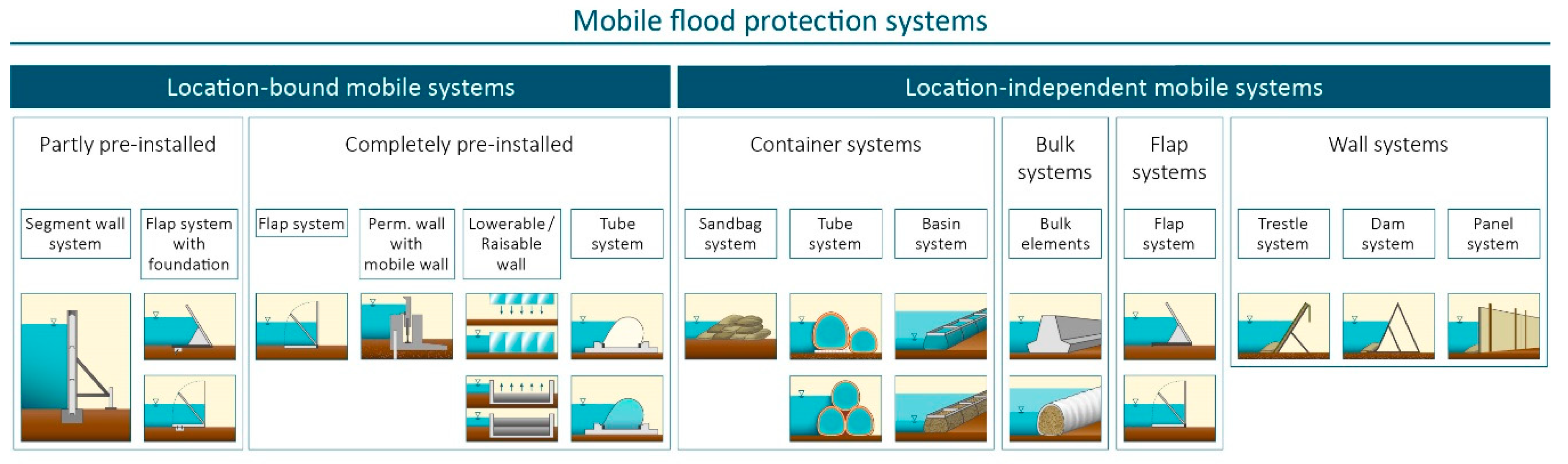
The mobile flood protection systems used in operational flood defense can be subdivided into location-bound and location-independent systems (Figure 1). Location-bound systems require permanent foundations or anchor points for sound installation, whereas location-independent systems can do without them. Due to the need for anchoring, location-bound systems have to be assessed and dimensioned on site and are frequently found where flood events occur regularly or closures in flood protection walls and dykes are required. Location-independent systems can be used flexibly and are particularly suitable for lower protection heights. In contrast to location-bound mobile systems, they are often used without specific dimensioning and detailed pre-planning, so that their use is generally riskier. In the following study, only location-independent systems will be considered, since their flexible and frequently spontaneous deployment makes them particularly relevant for operational flood defense against extreme events.
The sandbag system (sandbag dam) is a conventional system that is not tied to a specific location. Its advantage lies in its flexible deployment. In addition to the use of sandbag systems, it is also possible to use so-called sandbag replacement systems (SBRSs): these can be put in place much faster and are labor- and resource-saving. Accordingly, SBRSs can be used to set up a longer protective section in a shorter time.
SBRSs are divided into tube, basin, flap, trestle, dam, panel, or bulk systems. Tube and basin systems counteract the horizontal water pressure by the weight of their filling material, such as water or sand. There are also air-filled tube systems, which are held in place by the static friction caused by the flood water resting on force-fit connected plastic aprons laid horizontally on the ground. In contrast, flap, trestle, and dam systems use the vertical water pressure with their geometry to withstand horizontal water pressure. Bulk elements consist of high-density materials such as concrete. Panel systems consist of panels which are fastened to stakes driven into the ground on alternate sides.
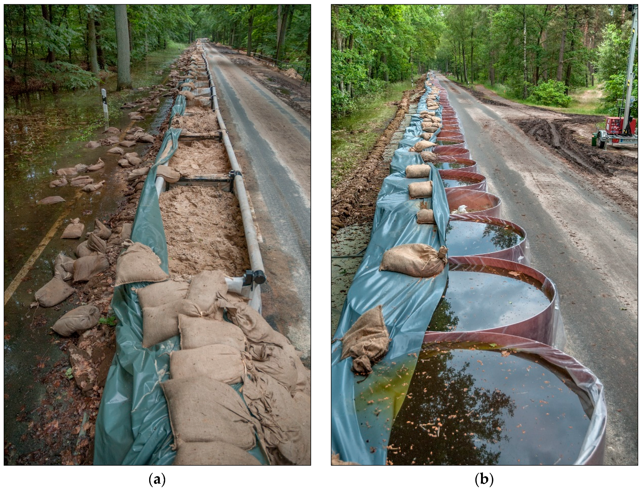
The disadvantages of SBRSs compared to sandbagging are, on the one hand, the high acquisition costs. However, when properly stored and maintained, SBRSs are completely or to a large extent reusable, whereas sandbags and sand must be disposed of separately and at high cost after use. In addition, there is the risk of vandalism or damage from external influences, especially with water- and air-filled SBRSs. Sandbags are comparatively easy to handle and their functionality has been proven over many years [5]. SBRSs, on the other hand, require trained personnel for installation and their use in flood defense is little known. However, SBRSs were used sporadically during the Elbe flood in 2013 (Figure 2).
In order to guarantee the functional capability of SBRSs in flood abatement, the system to be used must be tested in advance. Germany currently has no certification or testing system in place for checking the functionality of SBRSs, so that systems can be brought onto the market even without independent certification. The situation is different in Great Britain. Working in cooperation with various organizations, the British Standard Institution (BSI) developed a standard (PAS 1188-2) in 2003 that specifies how SBRSs must be tested for functionality [6]. In 2009 and 2014, PAS 1188-2 was updated and upgraded to the latest technological standards. The BSI offers international certification and testing services in which SBRSs are tested according to PAS 1188-2 and can receive a corresponding seal of approval. The precise number and test results of BSI certified systems are not available.
In 2003, the U.S. Senate Appropriations Subcommittee on Energy and Water Development commissioned the Engineer Research and Development Center (ERDC) of the U.S. Army Corps of Engineers (USACE) to develop a test facility and carry out realistic test series on SBRSs [7]. Full-scale laboratory tests were subsequently performed in the USACE testing halls, albeit under optimal conditions on a smooth concrete surface [8]. A sandbag dam, two basin systems with sand filling, and one trestle system were tested. The systems were subjected to loads caused by different water heads, mechanical impact, and wave motion. Under the pressure resulting from incoming waves, the sandbag dam was severely damaged and the system failed completely during the subsequent overtopping test. The SBRSs, however, were able to withstand the stresses and strains and showed only minor damage after the impact tests. To compare the laboratory results, the systems were installed along a riverbank on a surface of natural turf. The main focus of this series of tests was to erect the systems under real conditions, taking into account the parameters of accessibility and the surface of the area to be protected. Owing to the progressive softening of the subsoil caused by heavy construction machinery during the installation phase and the increased difficulty of access to the test area, the field tests showed longer construction times than the laboratory tests.
The results of the test series served as a basis for the development of the American National Standards for Flood Abatement Equipment ANSI/FM Approvals 2510, which were developed by the internationally active testing and certification service FM Approvals, first published in 2006 [9] and updated in 2014 [10]. The test guideline contains a comprehensive description of the test methods and structures as well as corresponding guideline values for the certification of a flood protection system. Information on the number and test results of systems certified by FM Approvals is only available in isolated cases [11].
As there is a large number of SBRSs, the Environment Agency of the United Kingdom published a guide in 2011 for the selection of temporary and demountable flood protection systems, in which evaluation criteria were established and evaluated according to manufacturers’ specifications. While the guide shows a wide range of existing SBRSs and their possible applications, it contains no verification of manufacturer’s data regarding possible water-head heights and stability behavior during situations of extreme loads [12].
Comparisons of SBRSs and sandbag systems as well as the possibility of significantly shortening the construction time of a flood barrier by using SBRSs are frequently cited in the literature (e.g., [13,14,15]). Various SBRSs have been tested since 2010, mainly on behalf of manufacturers, at the TuTech Centre for Climate Impact Research—KLIFF—at the TU Hamburg, Germany. These tests have mostly been conducted according to the criteria set forth in the test guidelines of the ANSI/FM Approval 2510 flood abatement equipment test standard. The tests took place in a test basin on a smooth concrete surface [16], which provided comparatively good underlying surface conditions for many of the constructions tested. Information on the tests has only been published in parts by the manufacturers (e.g., [17,18,19]).
In addition to the functional capability of SBRSs in the event of flooding and the higher investment costs for their acquisition, other aspects such as storage, durability, and transport of the systems also play a role. The amount of material required in the event of flooding is minimized by the use of SBRSs, so that if necessary, the systems can be transported over long distances to where they are needed. However, owing to the systems’ greater complexity compared to sandbags, there may be disruptions in the delivery of the system components. With water-filled SBRSs, for example, it is essential that sufficient pump capacity is available on site. With other SBRSs, the small connecting elements that are essential for assembly must be available.
Because SBRSs, owing to their functionality and their material-, labor- and time-saving characteristics, can make a crucial contribution to operational flood defense—especially in view of the expected consequences of climate change—and since hardly any experience has been published so far on the operational suitability of such systems, the Institute for Hydraulic and Coastal Engineering of the Bremen University of Applied Sciences, Germany (IWA) has carried out systematic test setups of SBRSs. The focus of the test setups was on the time needed for installation, possible water heads, system stability, and the seepage rates of SBRSs. The test facility has a turf floor, which allows the systems’ functional capability to be tested under more realistic conditions than the ideal conditions created by a concrete floor. Further parameters such as investment costs, storage, shelf life, and logistics related to SBRSs could not be dealt with in the frame of the present study. The results from the test series are intended to contribute toward an improved testing procedure for SBRSs and a further establishment of SBRSs in operative flood defense.
2. Materials and Methods
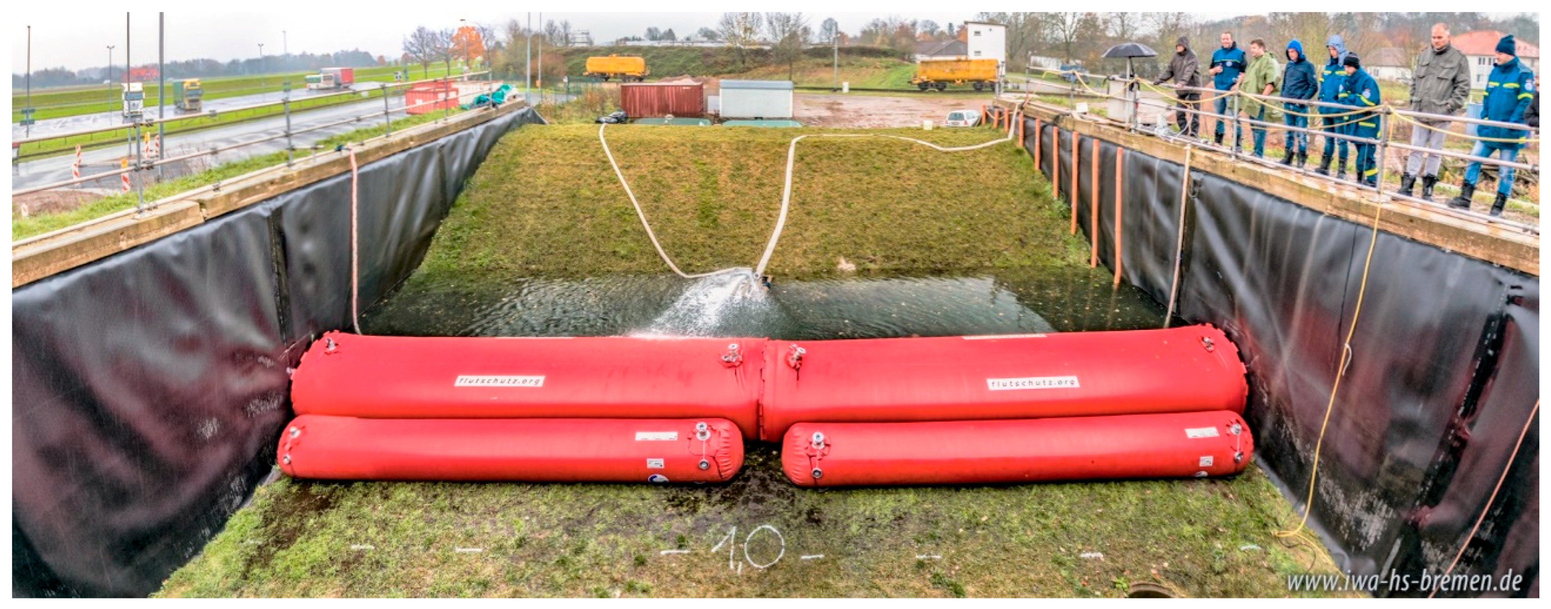
The test setups were carried out in the IWA test facility, which was developed as part of the DeichSCHUTZ research and development project funded by the German Federal Ministry of Education and Research (BMBF). The IWA test facility consists of a 3.5 m high U-shaped basin. A 3.0 m high dyke closes the 15 m wide opening. The basin can be filled with water, so that the load on the dyke or on installed flood protection systems by high water levels can be simulated. The basin floor consists of an approximately 1 m thick alluvial clay layer, on which topsoil and grass are applied to simulate the usual soil structure found in the middle and lower reaches of river basins. For the SBRS tests, the systems were constructed parallel to the dyke line over the entire width of the basin. The space between the dyke and the system was then filled with water (Figure 3). Owing to the hydrostatic pressure generated in this way, the hydrostatic load could be realistically simulated. The IWA test facility is not able to investigate other load variables such as current, waves, wind, flotsam, or vehicle impact, and environmental influences.
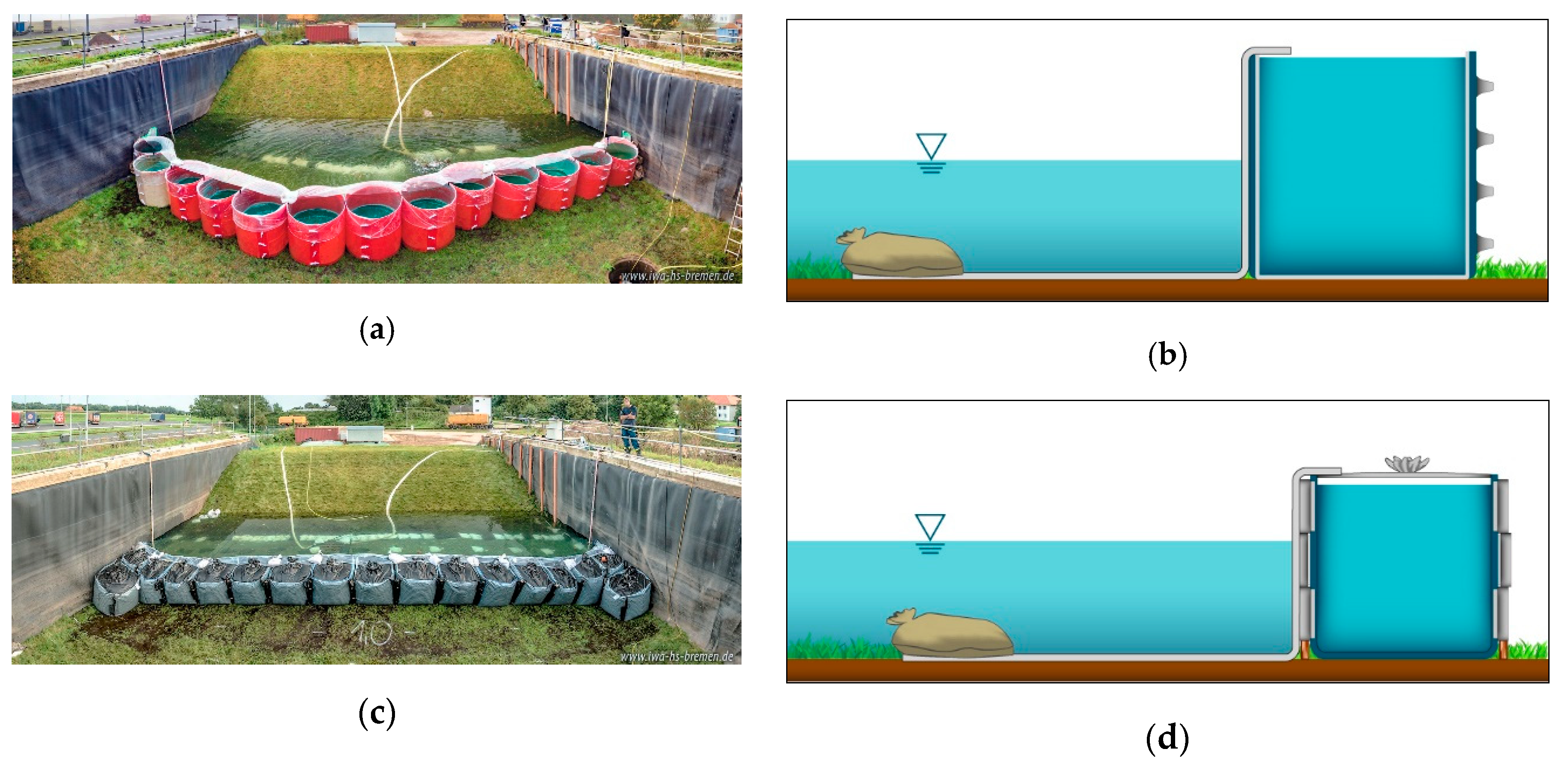
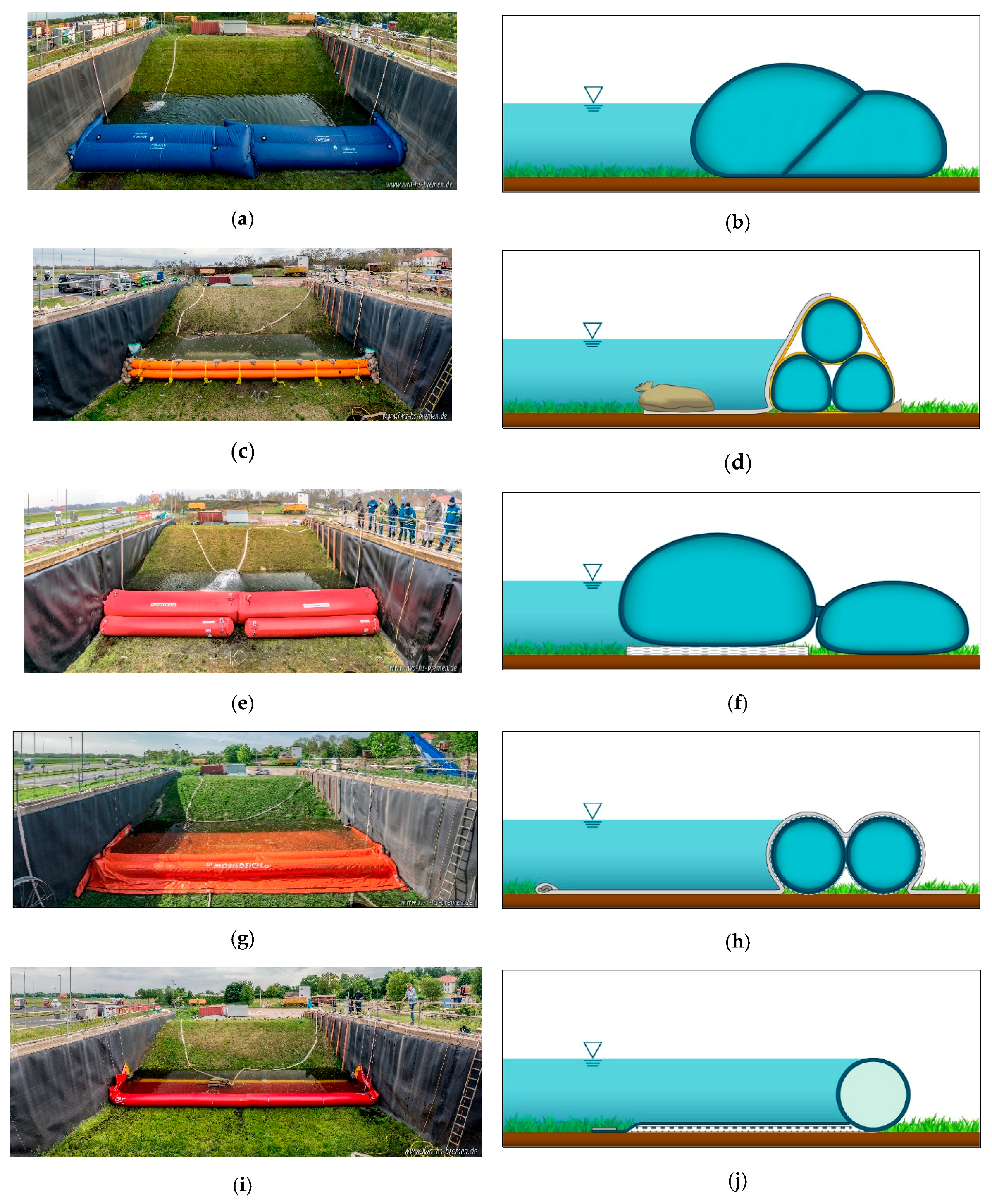
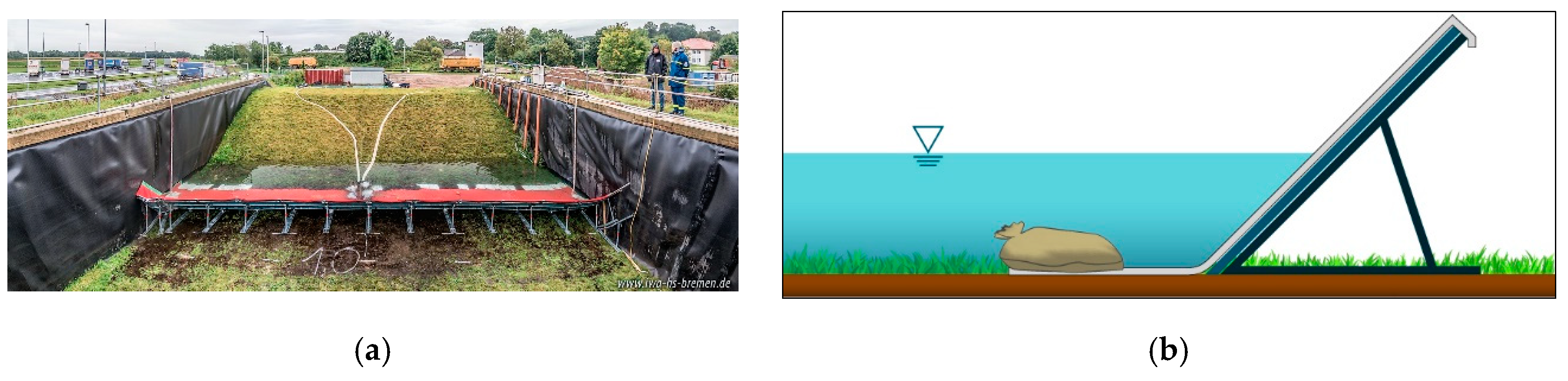
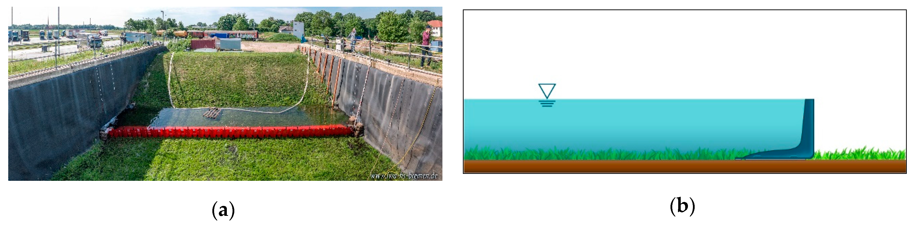
Since not all systems available on the market could be tested, a selection was made for the test setups. The systems were selected according to the type of construction and the willingness of the manufacturers to make the systems available for the test setups. The SBRSs which were examined in the test setup can be subdivided into basin systems (Figure 4), tube systems (Figure 5), trestle systems (Figure 6), and dam systems (Figure 7). There are only a few flap systems available on the market and no manufacturer was prepared to provide a suitable system for the test setups. Owing to the framework conditions, bulk elements and panel systems were not taken into account. The use of bulk elements takes place primarily in the headwaters of rivers due to the load variables flow dynamics, prevailing bedloads, and the high technical requirements needed for installation. The use of panel systems is limited to suitable soils and low dam heights.
In cases where the suppliers offered more than one system size, a variant suitable for a water head of 0.6 m was selected. This height corresponds to the recommendations contained in the technical bulletin ”Mobile Flood Protection Systems” published by the Association of Engineers for Water Management, Waste Management and Cultural Construction (BWK) [20] for the unplanned use of SBRSs in operational flood protection. The recommendation results, on the one hand, from the increasing danger of ground-foundation failure with increasing dam height as well as from not being able to dimension in advance the systems to cope with the loads occurring at an unknown location. The maximum dam head indicated minimizes the risk of damage. If larger system heights are required, the risk must be weighed on a case-by-case basis. Although a competent person should investigate the conditions expected on site before an SBRS is used, the requisite time and information are usually not available. Since some of the systems tested are not specifically designed for a water head of 0.6 m, oversized systems were also installed—AQUARIWA, aqua defense, Hydrobaffle, and Tiger Dam. The NOAQ Boxwall system only reaches a height of 0.5 m but was nevertheless tested due to its extremely simple functionality. According to the manufacturer, the Tiger Dam tube system can be used either with or without additional plastic aprons on the water side, and both variants were tested. The SBRSs were each set up by just two persons. With the exception of the SBRSs Mobildeich, Öko-Tec, and Tiger Dam, which consist of a single element covering the entire length of the basin width, the linear connection of individual elements was integrated into the test series. The connections at the basin edges were sealed with tarpaulins and sandbags.
With the exception of NOAQ Boxwall, which only impounds water up to 0.5 m owing to its low system height, the water level was initially set up to 0.6 m, which is in accordance with the BWK recommendations [20]. Load cells installed on the left side—viewed from the dyke—directly in front of the system enabled the digital control and documentation of water levels during the test series. Any seepage water escaping during the test was collected in a ditch and pumped back into the impounded water with the aid of a submersible pump and fire hoses. An intermediate magnetic-inductive flow sensor (MID) was used to measure the seepage volume at the water level of 0.6 m. The seepage rates are of particular importance when neighboring settlements, industrial plants, or individual buildings have to be protected with an SBRS during a flood event and the seepage water from the area to be protected has to be pumped to the water side. In such cases, the requisite pumps can be dimensioned in accordance with the monitored seepage rates. At a defined water level, the time required to achieve a steady seepage rate depends primarily on the permeability of the system and its adaptability to the floor it rests on. For this reason, the times needed to steady the seepage rate of the various systems also differ. Some systems had to have water impounded overnight to achieve a stationary seepage rate.
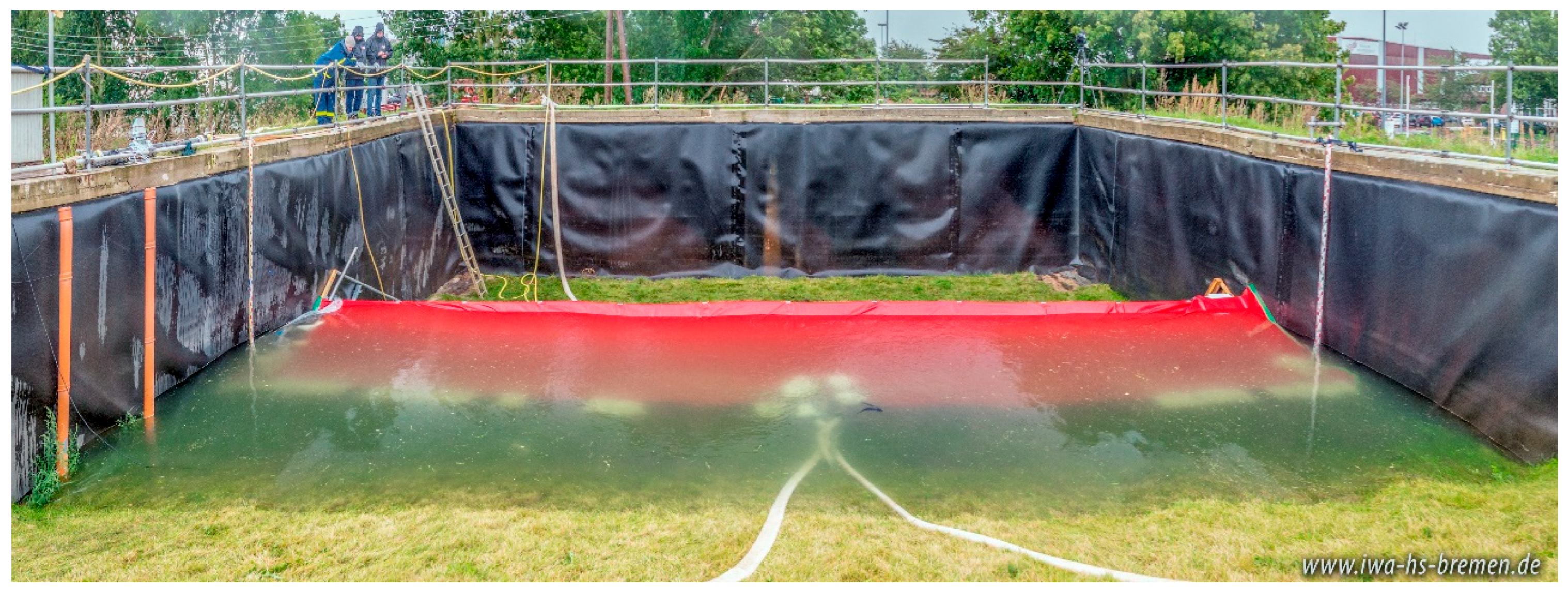
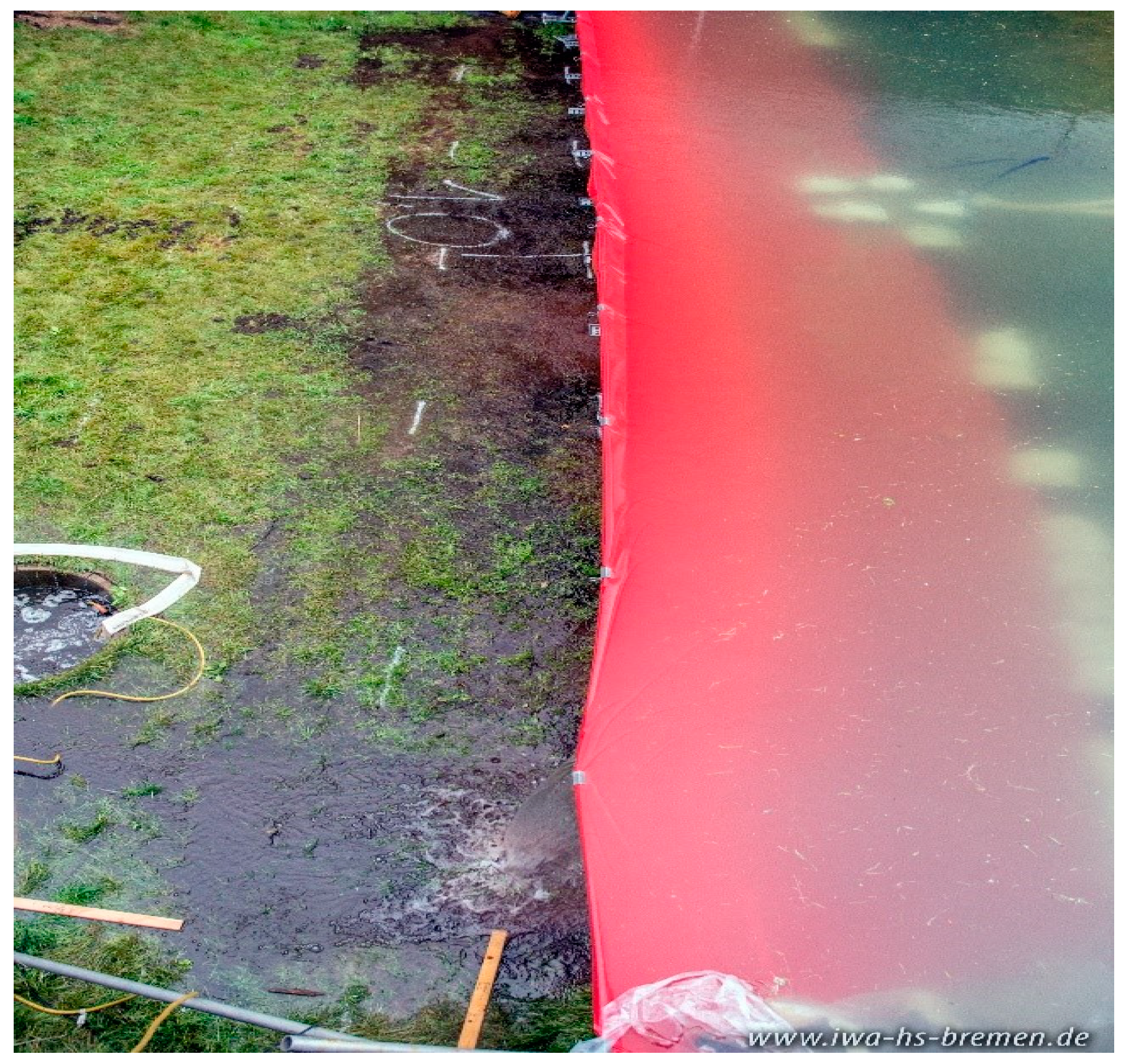
After reaching a steady seepage rate at a dam height of 0.6 m, the water in the basin was impounded in stages until system failure due to a water head exceeding the load limits of the system was reached or the system started to overflow. However, if the SBRS tested could withstand full impoundment or even overflow, these load cases could not be realized over the entire system length due to the unevenness of the basin floor and limited pumping capacity. Because of such unevenness, only a slight overflow height could occur on the left-hand side of the IWA test facility—viewed from the dyke (Figure 8).
When an SBRS overflows, one has to ensure that the ground the system rests on remains stable, that is, that the overflowing water does not cause soil erosion on the land side. In addition, the overflowing water masses must be discharged or distributed over a sufficiently large area. Theoretically, an SBRS can overflow if the system is sealed via vertical water pressure, since with increasing water levels the system is increasingly held stable via the vertical water pressure. Protruding plastic aprons on the water side, which are frequently used in water-filled systems, also favor the possibility of a higher water level, as this minimizes buoyancy forces underneath the system. Whether the system will overflow depends on its geometry and/or weight. With increasing water impoundment, the probability of failure due to tilting or slipping/rolling increases. Systems which are not able to use the effect of vertical water pressure for stabilization are not stabilized further with an increasing water level so that the resulting equilibrium of the acting forces is decisive for stability or overflow. In terms of stability, a high weight and/or a low center of gravity are fundamentally advantageous here. The tests do not take into account the possibility of the ground giving way with increasing water impoundment, since damming within the test setups only took place on a defined and stable floor.
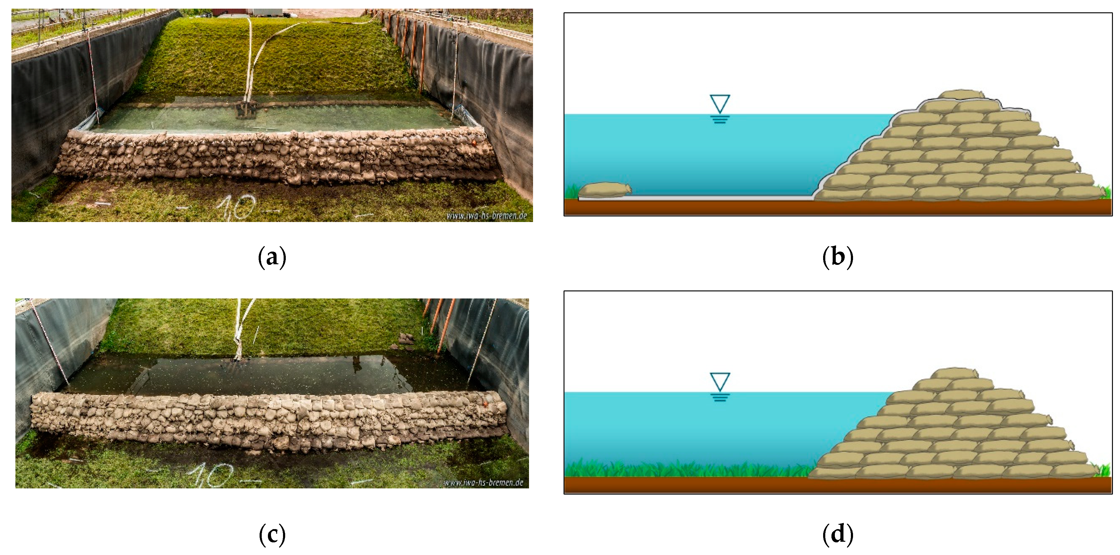
The stability of a sandbag dam is known from many years of practical experience. In order to obtain a comparison with the SBRS, especially with regard to seepage rates and installation times, two variants of a sandbag dam were also installed—with and without protruding plastic aprons on the water side (Figure 9). The sandbag dam was designed for a protection height of 0.6 m and 0.2 m freeboard, resulting in a height of 0.8 m and a base width of 2.1 m. Due to the larger material requirements needed for the construction of a sandbag dam, it took 16 people to build it (Figure 9). It took 16 persons about 3 h to fill the required 2000 sandbags with b/h = 40/60 cm (empty dimension). This was not included in the construction time of the sandbag dam, since only the construction at the place of use was considered for comparison.
3. Results
In the following section, the obtained results of the individual SBRSs with regard to installation times, possible water heads as well as system stability and seepage rates during water impoundment are discussed.
3.1. Installation Times
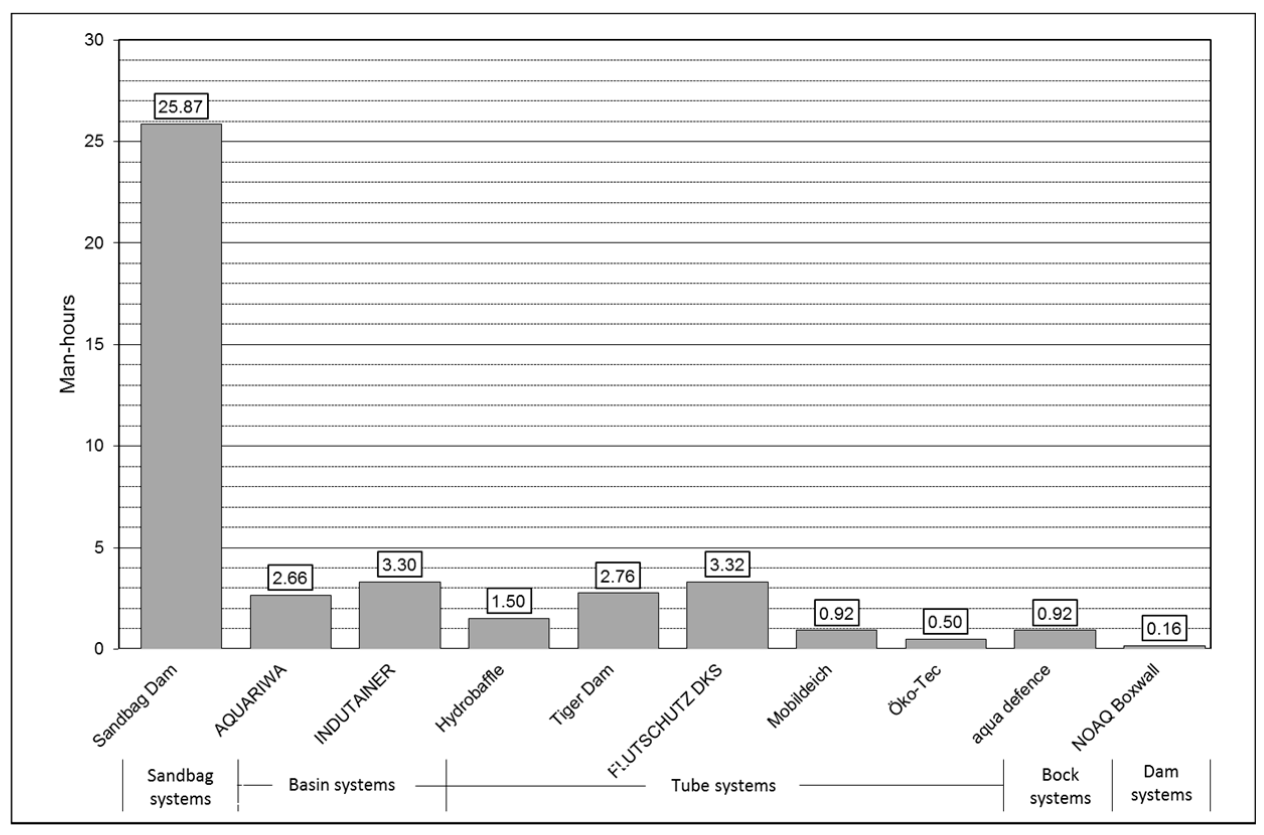
The required construction times of the sandbag dam and the SBRSs for a 15-m-long protection line and a protection height of 0.60 m are shown in Figure 10. Converted into man-hours, a comparison shows that the installation of the SBRSs is many times faster than the construction of a conventional sandbag dam, which takes about 26 man-hours. Due to the comparatively large volume of water required to fill the construction, the 3.3 man-hours needed to install the FLUTSCHUTZ-DKS is the longest among the SBRSs. Compared to the 26 hours required to build the sandbag dam, however, the time needed—one eighth of this—is relatively short.
In some cases, there were major differences between the manufacturer’s time specifications and the times measured during the test setups. For the setup, the systems had to be transported manually from the edge of the basin to the point of installation and thus over a maximum distance of 15–20 m. The systems had to be transported manually. It is quite conceivable that faster installation times can be achieved on surfaces that can be travelled on and which offer better logistical conditions. On the other hand, significantly longer manual transport distances and thus longer assembly times compared to the test conditions may occur in practice. The installation times of the water-filled SBRSs also depend strongly on the available pump capacity and the water supply. In principle, however, it can be said that the assembly and disassembly of the systems are generally possible with two persons and are many times faster than the construction of a sandbag dyke. In addition, it is also possible to optimize the assembly times by using more helpers. Systems that have no need of filling also show a clear time advantage during assembly and dismantling.
3.2. Maximum Water Heads and Stability
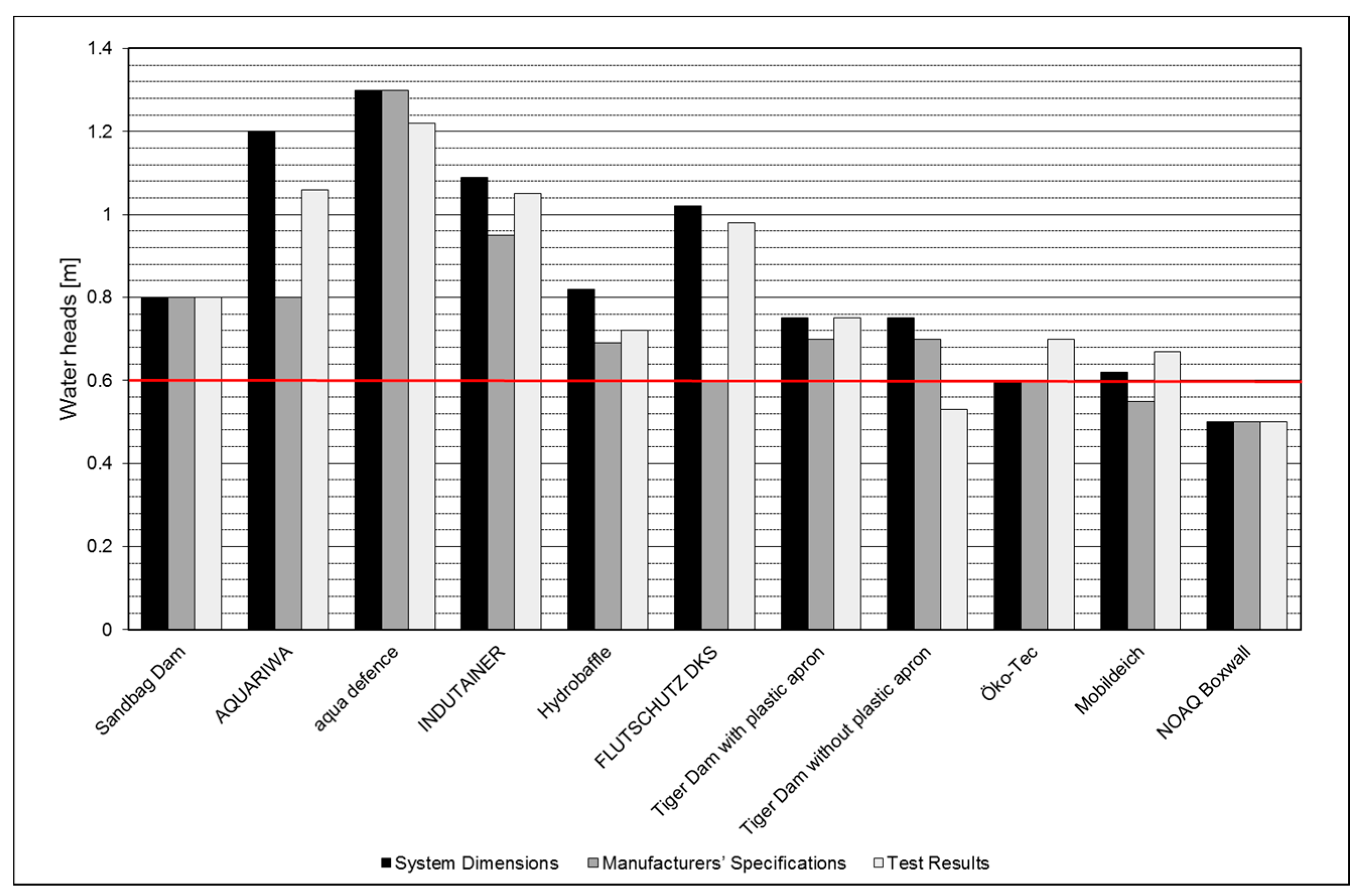
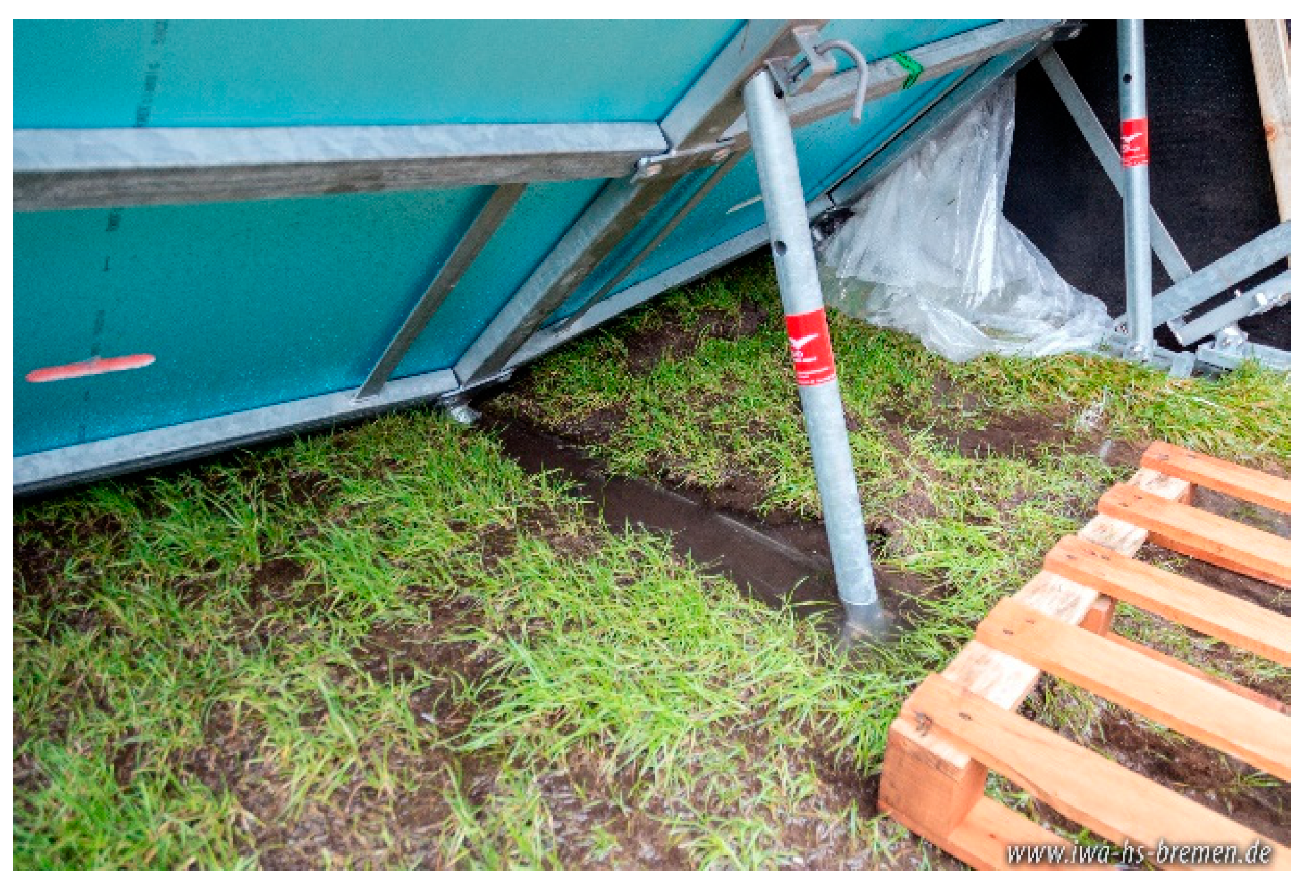
After reaching a steady seepage rate at a dam height of 0.6 m, the water level was successively raised to test the possible dam heights according to the manufacturer’s specifications and to determine the maximum load limits until failure of the systems on underlying turf. Figure 11 shows the system heights (black bar), the water heads specified by the manufacturers (grey bar), and the maximum water heads determined during the tests (light grey bar). The diagram shows that most of the tested systems fulfil the required 0.6 m (red line) in accordance with BWK recommendations [20]. Only the Tiger Dam was unable to achieve the required 0.6 m without a protruding plastic apron, whereas the variant installed together with a protruding plastic apron could be overflowed and achieved a maximum water head of 0.8 m. According to the manufacturer, the use of a protruding plastic apron is not mandatory for the construction of the Tiger Dam. However, based on the experience of the tests we carried out, one should always be used. The test results for the aqua defense system showed that the maximum water head specified by the manufacturer could not be achieved. The reason for this is that the supporting feet sank into the softened ground (Figure 12). However, it was possible for the system to overflow (Figure 13). The results of the Öko-Tec and Mobildeich tube systems showed that the maximum water level was higher than that of the systems. This is because the height of the system refers to the deployed system in the absence of hydrostatic load. As a result of the water impoundment, the tube systems in particular experienced a deformation due to horizontal water pressure, which had a positive effect on the system height and thus enabled a higher water head than that specified for the system.
In summary, it can be stated that all the tested systems reached the dam heights specified by the manufacturers and in some cases significantly exceeded them. The SBRSs aqua defense, Tiger Dam with plastic apron, Öko-Tec, Mobildeich, and NOAQ Boxwall were overflowable under the existing conditions in the test facility. Except for the Tiger Dam without plastic apron, all non-overflowable systems—AQUARIWA, INDUTAINER, Hydrobaffle and FLUTSCHUTZ DKS—had a low to high level of safety with regard to the required water head of 0.6 m and could be dammed higher before system failure occurred.
3.3. Seepage Rates
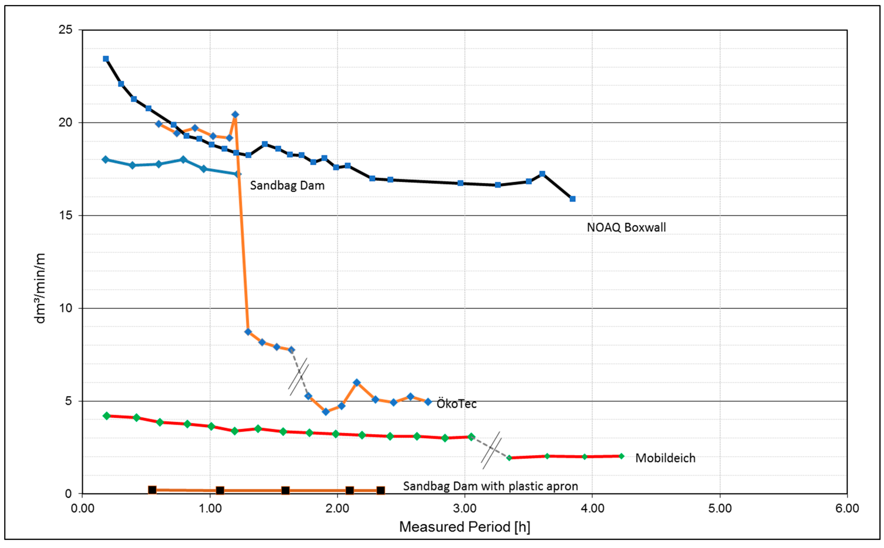
The measurement of the seepage rates of the sandbag dam as a reference value shows that it makes an enormous difference whether or not a system is fitted with a protruding plastic apron (Figure 14). A very low seepage rate of 0.17 dm3/min/m was determined with a protruding plastic apron, whereas the seepage rate in the absence of a protruding plastic apron was significantly higher at 17.0 dm3/min/m. If, for example, an area of 100 m is protected by a sandbag dam without a protruding plastic apron, approximately 100 m3 per hour seeps into the area to be protected. When using a sandbag dam with a protruding plastic apron, however, only 1 m3 per hour seeps into the area to be protected.
Figure 14 shows the SBRSs with the higher seepage rates and Figure 15, those with the lower seepage rates. In addition, Figure 14 shows the seepage rates for the sandbag dam with and without a protruding plastic apron. The SBRS NOAQ Boxwall (black line with blue dots) has an almost identical seepage rate as the sandbag dam installed without a protruding plastic apron (blue line). It should be mentioned here that although the system is not designed for use on an underlying surface of turf, it nevertheless shows a permeability comparable to that of a sandbag dam, whereas it can be installed in a significantly shorter time.
The situation is similar for the SBRS Öko-Tec (orange line with blue dots). The initial measurements show an increased seepage rate, which is due to an insufficient weighing down of the protruding plastic apron on the water side, which is part of the SBRS and force-fit connected to the air-filled tube. The manufacturer uses thin lead plates welded into the tarpaulin material to weigh the plastic apron down and keep it in place. During the tests, it was found that the weight of the protruding plastic apron was not enough to keep it flush with the underlying turf, which allowed an increased amount of water to seep under it. As a consequence, after approximately 1¼ h the plastic apron was additionally weighted down with sandbags. The resulting improved seal can be clearly seen in Figure 14, as the seepage rate was reduced from approximately 19.0 dm3/min/m to approximately 5.0 dm3/min/m.
The Öko-Tec and Mobildeich systems were dammed overnight during the test series, enabling the measurement with these systems over a longer period. During the night there was no measurement of leakage; this is shown by the interruption in the data line. During this measurement pause, the Öko-Tec seepage rate dropped overnight from 8.0 dm3/min/m to about 5.0 dm3/min/m and the Mobildeich seepage rate from 3.0 dm3/min/m to 2.0 dm3/min/m (Figure 14). The reason for this was that the protruding plastic apron achieved a better sealing effect with increasing damming time.
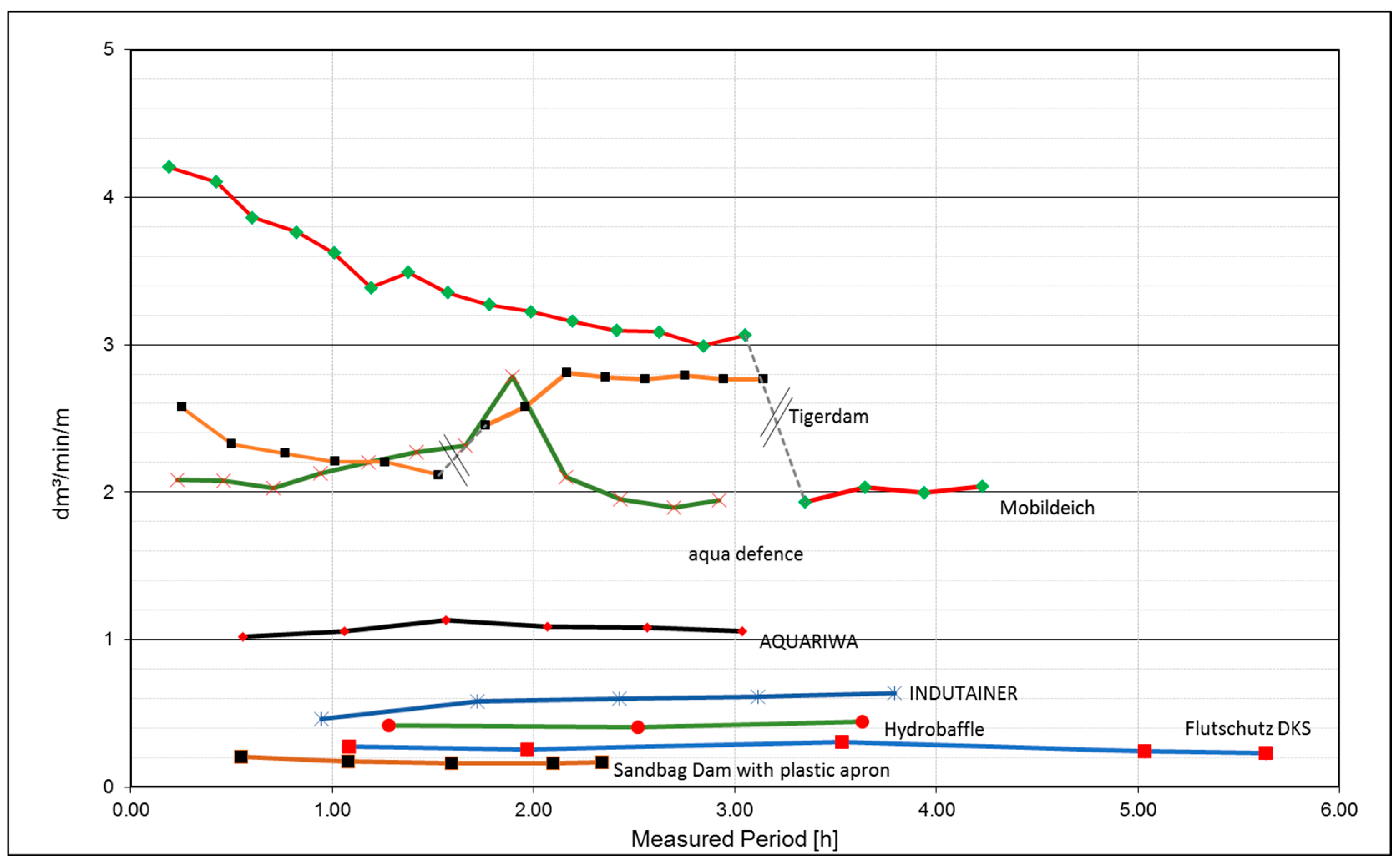
Figure 15 shows only the seepage rates of the low permeability SBRSs, so that a better comparison of the less permeable systems is possible. The seepage rate of the Mobildeich system (red line with green dots), which gradually decreases, stands out from the other systems. Here, a steel chain is used to weigh down the protruding plastic apron, which, due to its relatively low weight, only presses itself further into the underlying turf over time as the soil becomes softer before achieving an improved seal. A reduction in the seepage rate over time was also observed with the Tiger Dam (orange line with black dots), but the seepage rate increased slightly again from 2.1 dm3/min/m to 2.8 dm3/min/m during the measurement pause at night—shown by the interruption in the data line—after a slight shift in the construction at the edge connection. This was due to a slight displacement of the system at one edge connection, which allowed somewhat more water to pass through. It was not possible to rectify this fault while the basin was still full. The larger systems in terms of geometry, such as the FLUTSCHUTZ-DKS (light blue line with red dots) or the Hydrobaffle (green line with red dots), showed a lower permeability due to their higher weight and subsequent better seal to the underlying turf, and they are comparable with the sandbag dam fitted with a protruding plastic apron in terms of seepage rate.
In summary, it can be stated that the tested SBRSs have a significantly lower permeability than the sandbag dam without a protruding plastic apron with 17.5 dm3/min/m. With regard to seepage rates from 0.2 dm3/min/m to a maximum of 2.0 dm3/min/m, SBRSs also offer a good alternative to a sandbag dam with a protruding plastic apron, whose seepage rate is 0.17 dm3/min/m, or a sandbag dam without an apron, whose seepage rate is 17.0 dm3/min/m. According to BSI PAS 1188-2, the seepage rates to be observed are 40.0 dm³/h/m, namely, 0.67 dm3/min/m. These seepage rates were maintained on the existing test substrate by only a few of the SBRSs tested—INDUTAINER, Hydrobaffle, and Flutschutz DKS. However, it must be taken into account that the test structures were carried out on a much less favorable underlying surface with respect to permeability. According to ANSI/ FM Approvals, seepage rates of 3.1 dm3/min/m must be observed. These seepage rates were maintained by most SBRSs on the surface used for the tests. The NOAQ Boxwall system had the highest seepage rates. The distributor of the NOAQ Boxwall system states that, owing to its high permeability, it is not recommended to use the system on a grass substrate. The sandbag dam with a protruding plastic apron meets BSI requirements on the underlying surface used for the tests: the sandbag dam without a protruding apron neither meets the requirements of the BSI nor those of the ANSI.
4. Discussion
The results from the test series in the IWA test facility with different SBRSs show that these can be used very well in operative flood defense under consideration of the following parameters: construction times, possible water heads, and seepage rates on underlying turf. Each of the systems tested shows that it is possible to erect the protection line with fewer helpers in a significantly shorter time than with a time- and labor-intensive conventional sandbag dam. In the case of some SBRSs (Tiger dam, aqua defense, AQUARIWA), parts of the system sank into the turf during the damming procedure. To limit the test duration, the systems were only tested until a stationary seepage rate was reached. Thus, it is not possible to estimate from the test setups their suitability for use on grass over a flood event lasting up to several days. In addition to the short-term hydrostatic load tested, other factors such as hydrodynamic loads (currents and waves), mechanical loads (flotsam and vehicle impact), and vandalism can all affect the stability of an SBRS. The substrate also plays a major role in the stability of SBRSs—not least because the use of SBRSs makes it comparatively quick and easy to achieve greater water-head heights and thus generate large hydraulic loads. In principle, there is also the challenge that, in contrast to sandbag systems, SBRSs make greater technical demands on design and function. In the case of careless handling or the absence of trained personnel, assembly errors can occur: this can lead to system failure. Another disadvantage of SBRSs is the poorer adaptability of the individual element lengths. If the system is not explicitly designed for a certain gap, voids may occur at connection points or at the edges. However, due to the shorter distances, these can easily be closed with sandbags within a reasonable time. In addition, it is usually more difficult, if not impossible, to subsequently increase an SBRS in height to cope with higher flood levels. This is basically possible with sandbag dams, albeit with a correspondingly high expenditure of personnel, resources, and time. The operational capability of mobile SBRSs is basically limited to flood defense in inland areas, as the systems are highly susceptible to wind during assembly and sensitive to larger dynamic loads caused by waves. In the case of water-filled systems, for example, it is difficult to align the systems during installation in the event of heavy wind; and in the event of waves, the buoyancy forces in the wave crest can exceed the stabilizing forces.
The correct execution of corner and wall connections also plays a major role in determining seepage rates and stability. This aspect was not examined further in the system tests carried out. Moreover, the measurements of seepage rates also show that in systems fitted with a protruding apron, the lowest permeability is achieved when sandbags are used to weigh the apron down. In this respect, the sandbag still plays an important role in operational flood protection even when SBRSs are used. Without any doubt, the sandbag is indispensable in operational flood defense precisely because of its flexible operational capability.
In order to professionally promote the spread of SBRSs in operational flood protection, it is recommended to introduce the certification of SBRSs, since they are technical systems whose functional capability must be proven before their use in an emergency. A basis for developing a certification system in accordance with German standards is provided by the BWK recommendations ”Mobile Flood Protection Systems” [20] with the international certification systems such as FM Approvals [10] or BSI Kitemark [6], and the test results described here. Since SBRSs are used in case of flooding on different underlying surfaces such as grassland and turf, paving, and tarmac, it is important to take into account different types of surfaces in the certification because they can have a considerable influence on the system stability and the seepage rate.
Author Contributions
Conceptualization, B.K.; Methodology, C.M. and L.L.; Resources, C.M. and L.L.; Data curation, C.M.; Writing—original draft preparation, C.M. and L.L.; Writing—review and editing, B.K., C.M., and L.L.; Visualization, C.M.; Supervision, B.K.; Project administration, B.K.; Funding acquisition, B.K.
Funding
This research was funded by the German Federal Ministry for the Environment, Nature Conservation and Nuclear Safety, grant number 03DAS080, the German Federal Ministry of Education and Research, grant number 13FH015PX4, the German Federal Agency for Technical Relief Foundation and City University of Applied Sciences, Bremen, Germany.
Acknowledgments
The authors wish to thank the THW Training Centre Hoya for the opportunity to erect the IWA test facility on the THW premises and for the technical support during the test series. They would also like to thank the manufacturers of SBRSs for providing the systems, the THW flood protection and dyke defense course for the construction of the sandbag dam, and the student assistants for their enthusiastic cooperation during the test series.
Conflicts of Interest
The authors declare no conflict of interest. The funders had no role in the design of the study; in the collection, analyses, or interpretation of data; in the writing of the manuscript; or in the decision to publish the results.
References
- Deutscher Feuerwehrverband e.V Home Page. Available online: http://www.feuerwehrverband.de/79.html?&tx_news_pi1%5Bnews%5D=108&tx_news_pi1%5Bcontroller%5D=News&tx_news_pi1%5Baction%5D=detail&cHash=3db80d8477deec8caf0638bcb20def21 (accessed on 3 December 2018).
- Crisis Prevention Home Page. Available online: https://crisis-prevention.de/feuerwehr-katastrophenschutz/zahlt-sich-praevention-aus (accessed on 3 December 2018).
- German Federal Agency for Technical Relief Home Page. Available online: https://www.thw.de/SharedDocs/Meldungen/DE/Pressemitteilungen/national/2013/07/pressemitteilung_003_hochwasserbilanz.html?noMobile=1 (accessed on 3 December 2018).
- Lehmann, G. Hochwasserschutz und Deichverteidigung im THW (Flood Protection and Dyke Defence for THW-Helpers); German Federal Agency for Technical Relief Ausbildungszentrum: Hoya, Germany, 2018. [Google Scholar]
- Technisches Hilfswerk Projektgruppe Hochwasserschutz und Deichverteidigung Home Page. Available online: https://pg-deich.thw.de/deich-verteidigung/ (accessed on 3 December 2018).
- British Standards Institution. Temporary products. In Flood Protection Products—Specification, 3rd ed.; The British Standards Institution Group Headquarters: London, UK, 2014; ISBN 978 0 580 85754 6. [Google Scholar]
- House of Representatives Home Page. Available online: https://www.congress.gov/congressional-report/108th-congress/house-report/357/1?overview=closed (accessed on 3 December 2018).
- Flood-Fighting Structures Demonstration and Evaluation Program: Laboratory and Field Testing in Vicksburg, Mississippi. Available online: https://www.researchgate.net/publication/235135012_Flood-Fighting_Structures_Demonstration_and_Evaluation_Program_Laboratory_and_Field_Testing_in_Vicksburg_Mississippi (accessed on 13 December 2018).
- FM Approvals Hompage. Available online: https://www.fmapprovals.com/about-fm-approvals/history (accessed on 3 December 2018).
- American National Standard for Flood Abatement Equipment; American National Standards Institute and FM: Norwood, MA, USA, February 2014; ANSI/FM Approvals 2510.
- National Flood Barrier Testing & Certification Program Hompage. Available online: http://nationalfloodbarrier.org/product-categories/temporary-flood-barriers/ (accessed on 3 December 2018).
- Ogunyoye, F.; Stevens, R.; Underwood, S. Delivering Benefits through Evidence: Temporary and Demountable Flood Protection Guide; Defra-Environment Agency: Bristol, UK, 2011; ISBN 978-1-84911-225-3. [Google Scholar]
- McCormack, S.M.; VanDyke, C.; Suazo, A.; Kreis, D. Temporary Flood Barriers; University of Kentucky: Lexington, KY, USA, 2012. [Google Scholar]
- Koppe, B.; Brinkmann, B. Opportunities and drawbacks of mobile flood protection system. In Proceedings of the International Conference on Coastal Engineering ICCE, Shanghai, China, 30 June–5 July 2010. [Google Scholar]
- Biggar, K.; Srboljub, M. Alternatives to Sandbags for Temporary Flood Protection; Alberta Transportation and Utilities: Edmonton, AB, Canada; Disaster Services Branch and Emergency Preparedness Canada: Ottawa, ON, Canada, 1998. [Google Scholar]
- Koppe, B.; Gabalda, V.; Manojlovic, N. Test von mobilen Hochwasserschutzkonstruktionen im Forschungsprojekt SMARTeST (Test of Mobile Flood Protection Installations in the SMARTeST Research Project); Ernst & Sohn: Berlin, Germany, 2012. [Google Scholar]
- AQUABURG Hochwasserschutz GmbH Home Page. Available online: https://www.aquaburg.com/tag/tuhh/ (accessed on 3 December 2018).
- AquaFence Home Page. Available online: https://www.aquafence.com/about-us (accessed on 3 December 2018).
- Flutschutz Home Page. Available online: http://www.flutschutz.org/entwicklung/entwicklung-d.html (accessed on 3 December 2018).
- Bund der Ingenieure für Wasserwirtschaft, Abfallwirtschaft und Kulturbau (BWK) e.V. Merkblatt: Mobile Hochwasserschutzsysteme—Grundlagen für Planung und Einsatz; BWK-Bundesgeschäftsstelle: Sindelfingen, Germany, 2005; ISBN 3-936015-19-8. [Google Scholar]
Figure 1.
Classification of mobile flood protection systems.

Figure 2.
SBRSs near Gartow (Lower Saxony, Germany) after the Elbe flood waters had receded in 2013: (a) QUICK-DAMM type E (b) AQUARIWA.
Figure 2.
SBRSs near Gartow (Lower Saxony, Germany) after the Elbe flood waters had receded in 2013: (a) QUICK-DAMM type E (b) AQUARIWA.

Figure 3.
Impoundment using an SBRS—FLUTSCHUTZ-Doppelkammerschlauch—in the IWA test facility.

Figure 4.
Basin systems tested in the IWA test facility, (a) AQUARIWA (water-filled), (b) schematic diagram of the AQUARIWA system, (c) INDUTAINER, (water-filled), (d) schematic diagram of the INDUTAINER system.
Figure 4.
Basin systems tested in the IWA test facility, (a) AQUARIWA (water-filled), (b) schematic diagram of the AQUARIWA system, (c) INDUTAINER, (water-filled), (d) schematic diagram of the INDUTAINER system.

Figure 5.
Tube systems tested in the IWA test facility, (a) Hydrobaffle (water-filled), (b) schematic diagram of the Hydrobaffle system, (c) Tiger Dam, (water-filled), (d) schematic diagram of the Tiger Dam system, (e) Flutschutz Doppelkammerschlauch (DKS) (water-filled), (f) schematic diagram of the Flutschutz DKS system, (g) Mobildeich, (water-filled), (h) schematic diagram of the Mobildeich system, (i) Öko-Tec (air-filled), (j) schematic diagram of the Öko-Tec system.

Figure 6.
Trestle system tested in the IWA test facility, (a) aqua defense (non-filled), (b) schematic diagram of the aqua defense system.
Figure 6.
Trestle system tested in the IWA test facility, (a) aqua defense (non-filled), (b) schematic diagram of the aqua defense system.

Figure 7.
Dam system tested in the IWA test facility, (a) NOAQ Boxwall (non-filled), (b) schematic diagram of the NOAQ Boxwall system.
Figure 7.
Dam system tested in the IWA test facility, (a) NOAQ Boxwall (non-filled), (b) schematic diagram of the NOAQ Boxwall system.

Figure 8.
Overflowing SBRS—aqua defense.

Figure 9.
Sandbag flood protection system. (a) Sandbag dam with protruding plastic apron (b) schematic diagram of the sandbag dam with protruding plastic apron, (c) Sandbag dam without protruding plastic apron, and (d) schematic diagram of the sandbag dam without protruding plastic apron tested in the IWA facility.

Figure 10.
Time needed to install a 15 m location-independent mobile flood protection system expressed in man-hours.
Figure 10.
Time needed to install a 15 m location-independent mobile flood protection system expressed in man-hours.

Figure 11.
System dimensions, water heads according to manufacturers’ specifications, maximum water heads achieved during tests with location-independent mobile flood protection systems; the red line indicates recommended water heads according to BWK [20].
Figure 11.
System dimensions, water heads according to manufacturers’ specifications, maximum water heads achieved during tests with location-independent mobile flood protection systems; the red line indicates recommended water heads according to BWK [20].

Figure 12.
Supporting feet of the aqua defence system sinking into the ground.

Figure 13.
Water overflowing the aqua defence system.

Figure 14.
Selection of seepage rates of individual mobile systems with a water head of 0.6 m.

Figure 15.
Selection of seepage rates of individual mobile systems with a water head of 0.6 m.

© 2018 by the authors. Licensee MDPI, Basel, Switzerland. This article is an open access article distributed under the terms and conditions of the Creative Commons Attribution (CC BY) license (http://creativecommons.org/licenses/by/4.0/).
Share and Cite
MDPI and ACS Style
Massolle, C.; Lankenau, L.; Koppe, B. Emergency Flood Control: Practice-Oriented Test Series for the Use of Sandbag Replacement Systems. Geosciences 2018, 8, 482. https://doi.org/10.3390/geosciences8120482
AMA Style
Massolle C, Lankenau L, Koppe B. Emergency Flood Control: Practice-Oriented Test Series for the Use of Sandbag Replacement Systems. Geosciences. 2018; 8(12):482. https://doi.org/10.3390/geosciences8120482
Chicago/Turabian StyleMassolle, Christopher, Lena Lankenau, and Bärbel Koppe. 2018. "Emergency Flood Control: Practice-Oriented Test Series for the Use of Sandbag Replacement Systems" Geosciences 8, no. 12: 482. https://doi.org/10.3390/geosciences8120482
Note that from the first issue of 2016, this journal uses article numbers instead of page numbers. See further details here.