Review

Overview of Actuated Arm Support Systems and Their Applications

1
Electromechanics and Power Electronics (EPE), Eindhoven University of Technology, Den Dolech 2, 5612 AZ, Eindhoven, The Netherlands
2
Zuyd University of Applied Sciences, Henri Dunantstraat 2, 6419 PB Heerlen, The Netherlands
3
School for Public Health and Primary Care (CAPHRI), Maastricht University, Duboisdomein 30, PO Box 616, 6200 MD Maastricht, The Netherlands
4
Focal Meditech BV, Droogdokkeneiland 19, 5026 SP Tilburg, The Netherlands
*
Author to whom correspondence should be addressed.
Actuators 2013, 2(4), 86-110; https://doi.org/10.3390/act2040086
Submission received: 8 August 2013 / Revised: 12 September 2013 / Accepted: 26 September 2013 / Published: 2 October 2013
(This article belongs to the Special Issue Human Centered Actuators)

Abstract

:
Arm support systems provide support throughout daily tasks, training or in an industrial environment. During the last decades a large diversity of actuated arm support systems have been developed. To analyze the actuation principles in these systems, an overview of actuated arm support systems is provided. This overview visualizes the current trends on research and development of these support systems and distinguishes three categories. These categories depend mainly on the functional status of the user environment, which defines the specifications. Therefore, the actuated arm support systems are classified according to their user environment, namely: ambulatory, rehabilitation and industrial. Furthermore, three main actuation principles and three mechanical construction principles have been identified.

Graphical Abstract

1. Introduction

A wide diversity of arm support systems are developed to support the upper limb function. Within these developments several fields of application can be distinguished. Firstly, devices assisting someone with a limited arm function that provide support during activities of daily living (ADL) [1]. Secondly, devices that provide support during training as part of the rehabilitation process [2]. Lastly, devices that enhance the arm function of healthy persons [3] or can be used for teleoperation and virtual reality [4].
Overviews and reviews of developed arm support systems are already provided in the literature. The majority of these publications consider rehabilitation devices used for neurological lesions [5,6,7]. The devices are evaluated on the mechanical structure, the range of motion (ROM), supporting segments (i.e., shoulder, elbow etc.), and the degrees of freedom (DOF) to provide a good support to humans. Other publications focus on the user functionality provided by arm support systems designed for use at home [8]. A more technical approach is given in [9] which includes the actuation principles. Publications from a technical prospectus are e.g., a review of the development of exoskeletons [10], the used control strategies [11,12], the complete mechanical design [13] and the shoulder mechanism design in particular [14]. A review of robotic systems in general, concerning the actuation principles, sensing methods and control strategies, is given in [15].
Figure 1. Proposed overview of the arm support systems.
Actuators 02 00086 g001
This paper presents, in contrast with existing overview papers, a technical overview with focus on the applied actuators and their performance. The actuation principles and the existing actuation configurations are discussed to provide more insight in their operation. Furthermore, the use of compliant actuators and their control bandwidth are compared. From the provided force and torque specifications, the order of magnitude for the actuator specifications used in arm support systems can be deducted. These specifications depend mainly on the user environment, used actuation principle, and the actuator configuration (i.e., position of the actuators with respect to the mechanical construction). Therefore, an overview is presented from a design point of view: specifying the user environment, selecting the actuation principle and the actuator configuration as shown in Figure 1 [16] which will be elaborated further in Section 6.
In the first section the applications based on the user environments are defined. Afterwards, the actuation technologies applied in these arm support systems are described. Then, the actuator configurations are explained and the manner to achieve compliant actuators is discussed. Subsequently, a comparison of the torque and/or force specification are made between the applications and actuation technologies. Finally, future trends are given.
The literature study is performed using mainly the Inspec database. For this overview, mostly journal publications were used to show the possibilities of actuation principles in arm support systems. The reported results, facts, numbers, and recommendations were not validated by the authors.

2. Applications

The arm support systems are divided based on their application (i.e., on their user environment). In general, actuators are selected depending on a set of requirements such as the functionality the arm support must have. In literature, three groups of arm support system applications can be distinguished: ambulatory use, rehabilitation use, and industrial use.

2.1. Ambulatory

Ambulatory arm support (AAS) systems are intended for users with diminished arm functionality due to e.g., neuromuscular disorders, and for elderly [17]. Current trends also show preventive use of AAS systems for people who suffer from for example repetitive strain injury and muscle fatigue [18]. Their purpose is to assist during the ADL, such as eating, drinking, using the computer, etc. Usually, not the full ROM of a healthy human body is covered, only the ROM needed to compensate for the lost muscle activity or to avoid muscle fatigue. For this group of arm support systems, it can be desired to be inconspicuous; hence, stigmatization can be avoided. Furthermore, a certain movement characteristic can be desired, such as following the arm movements naturally or providing a stable support. Additionally, flexibility and simple mounting, e.g., on a wheel chair, is often desired. When mounted on a wheel chair, the energy consumption must be small to avoid recharging of the wheelchair battery during the day.

2.2. Rehabilitation

Rehabilitation arm support (RAS) systems are intended to assess the human arm impairments [19] and to regain the arm functionality by training [2]. People, who suffer from e.g., the repercussion of a stroke, an accident, or an progressive neuromuscular disorder [20], should benefit from these support systems. For rehabilitation and maintaining the muscle activity, the full ROM of ADL is desired [2,21]. RAS systems should be able to assist or even correct the user when he follows predefined trajectories. Usually, RAS systems are used in rehabilitation centers and are designed to be stationary; hence, they are not intended to be applied in a home situation. However, to provide rehabilitation possibilities at home, devices are being developed [22]. These home RAS systems should be lightweight, easy to carry, occupy a small volume, and have a low power consumption, whereas the majority of the RAS systems used in rehabilitation centers are designed to provide a large ROM and many different training possibilities. For training it is shown that haptics can be useful [23]. Furthermore, RAS systems require to store data to monitor progress in therapy. Therefore, stationary RAS systems have, in general, a larger volume, more complex mechanical structures, and more powerful actuators compared with mobile RAS and AAS systems.

2.3. Industrial

Industrial arm support (IAS) systems are intended to enhance the physical capabilities of healthy humans or to use them as master/slave devices. Enhancing the human capabilities can be desired because of ergonomic reasons or to move larger masses [24]. Depending on the working environment, the task to perform [24], and the power required, an additional power supply might be necessary (stationary or auxiliary). Master/slave devices are used to carry out procedures remotely (i.e., teleoperated) such as dismantling nuclear installations [25], or in virtual environments [4]. For these applications, haptics are required to provide the user a realistic experience [26]. In general, enhancing the human capabilities requires high torque, whereas the teleoperated and virtual environments only need to provide haptic feedback which will be further elaborated in Section 6.

3. Actuation Principle

The actuation principles applied in arm support systems are chosen based on the requirements of the arm support system. From the literature, three actuation principles and one damping method can be distinguished: Electromagnetic, pneumatic, hydraulic, and semi-active damping.

3.1. Electromagnetic Actuators

Electromagnetic actuators convert electrical energy through a magnetic link into mechanical motion. The majority of arm support systems use electrical motors which provide one degree of freedom (DOF) rotary motion. Most of the applied electrical motors are permanent magnet machines. From the permanent magnet motors, the brushed DC motors [27] and brushless DC motors [28,29] are the most popular.
Brushed DC motors are excited using brushes and a DC source. Because a DC source is required these motors can simply be connected to the batteries of an electric wheelchair. Brushless DC motors do not utilize brushes, however, they use more than one phase (in general three phases). Therefore, brushless motors require additional electronics and control to excite the multiple phases. As small motors are often chosen, brushed DC motors provide the highest performance, higher efficiency, and higher torque density [30].
High-speed and low-torque electric motors have a small volume with respect to high-torque low-speed electric motors. High-speed and low-torque electric motors are applied to avoid large and cumbersome constructions. Gears are used to provide the required torque, which means converting the high-speed low-torque into low-speed and high-torque. Commonly, gear ratios of 100:1, 300:1 or even higher are chosen. The disadvantage of such high gearing is their low efficiency, which is typically around 70% to even 50% [30].

3.2. Pneumatic Actuators

Pneumatic actuators have a good power-to-weight ratio, therefore, their suitability for arm support systems is investigated. Three pneumatic actuators principles are utilized in arm support systems: pneumatic cylinders, McKibben muscles, and pneumatic muscle actuators (pMAs).
In pneumatic cylinders, pressurized air is injected and, subsequently, a force is generated that moves the piston in the cylinder in a linear direction. Pneumatic cylinders can be single-acting (push or pull) or double-acting (push and pull). The McKibben muscle injects pressurized air into a pneumatic bladder; hence, the bladder will expand and the end parts will contract. This actuator is referred to as artificial muscle because it has a similar behavior to a human muscle. The McKibben muscle is only single-acting (pull) and, therefore, has less flexibility compared to the pneumatic cylinder. The pMA was developed by improving the McKibben muscle using improved modeling techniques and a novel construction. Due to the compressibility of air, pneumatic actuators have a non-linear behavior which requires a more advanced control strategy [24,31].
For all pneumatic actuator principles, an additional compressor is required to generate the necessary compressed air [32]. The air can be compressed externally and transported to a desired location. Depending on the implementation, pneumatic actuators are often associated with noise. Therefore, such actuation for arm supports during ADL could be experienced as unpleasant.

3.3. Hydraulic Actuators

Hydraulic actuators have the highest power-to-weight ratio and positional stiffness of all the aforementioned actuation principles [32]. Note that with this power-to-weight ratio only the cylinder is taken into account, not the total system such as the hydraulic pump. The appliance of hydraulic actuators can decrease the weight of the arm support and increase the actuator output [33]. From the literature, the following hydraulic actuation principles can be distinguished: Hydraulic cylinders [34], Hydraulic bilateral-servo actuator (HBSA) [33], and rotational HydroElastic Actuator rHEA [35].
Hydraulic cylinders function similar to pneumatic cylinders, however, a fluid is injected under pressure instead of pressurized air. The injected fluid is pressurized using a hydraulic pump. Analogous to the pneumatic cylinders, hydraulic cylinders can be constructed to produce a push and pull force. Hydraulic bilateral-servo actuators are very similar to the hydraulic cylinders, however, the electric motor combined with a lead screw is used to pressurize the fluid. This motor is usually placed directly attached or very close to the hydraulic cylinder and, therefore, this combination can be seen as one actuator. Because of this placement the hydraulic cylinder has low transmission losses. If multiple HBSA’s are utilized, each HBSA requires its own electric motor, whereas multiple hydraulic cylinders require only one hydraulic pump. The rHEA is a rotational hydraulic actuator combined with a mechanical spring. Comparable with hydraulic cylinders, a rotational hydraulic actuator uses blades to generate a force that produces a rotational motion.
When flammable and/or poisonous fluids are used, a high level of maintenance is required to prevent leakages [32].

3.4. Semi-Active Damping

Technically, semi-active dampers cannot be classified as an actuator since they provide a (speed dependent) reaction force and not an active force. Semi-active dampers consist of a piston and a fluid which viscosity can be adjusted using an electromagnetic field [36]. The semi-active damping principle is currently being researched for automotive applications [37,38,39]. One of the semi-active dampers used in arm support systems is the magnetorheological (MR) damper. By applying an electromagnetic field, the viscosity of the MR fluid increases which makes movement through the magnetorheological fluid more difficult. Using this in a rotary application, a minimal reaction torque exists when no magnetic field is applied and the reaction torque can be increased by increasing the magnetic field [40]. A reaction torque of 1.1 Nm [36] can be generated. This technology is used for tremor suppression. Additionally, it can be used as a slip clutch, by adjusting the electromagnetic field, the maximum torque of the slip clutch can be adjusted [41].

4. Compliant and Back-Drivable Actuation

Compliant actuators have an elastic output behavior which means the output will move when an external force is applied and it returns to its original state when the force is no longer present. More recent publications show that compliant actuators are preferred in arm support systems [27,34,42]. These actuators have a smaller impact force compared to stiff actuators and an external force on the output is less likely to damage the system. Therefore, compliant actuators are important from a safety point of view and to provide comfort.
Additional to compliant actuators, back-drivable actuators are also used to provide safety and comfort. This backdrivability depicts the amount of torque/force that has to be placed on the output in order to move the input and depends on the type of actuator, gear, and control. Non-back-drivable actuators, such as motors with lead screws, cannot rotate the output without rotating the input first. Back-drivable actuators with a high backdrivability only require a small torque/force on the output to move the input, whereas low backdrivability (due to high gear ratios) demands a large torque on the output to move the input. Furthermore, when the backdrivability is too low, the gearbox could be damaged even before the input will rotate when a sudden external force occurs on the arm.
Compliant actuation can be achieved by applying inherently compliant actuators such as pneumatic actuators. Pneumatic actuators are inherently compliant because of the compressibility of air [31,42,43,44,45]. This is the most mentioned reason, together with their high force density, of utilizing pneumatic actuators in the literature. Backdrivability can be realized by direct drive (i.e., without gears) or low geared electromagnetic actuators [46].
Actuators which are not inherently compliant or back-drivable such as hydraulic and electromagnetic actuators with a high gearing, can be made compliant or back-drivable through hardware and/or software. An often used hardware solution for compliant actuation is the series elastic actuator (SEA) [27,34,35,47]. A SEA has a mechanical spring in series with the actuator output and the mechanical structure. By controlling the tension of this spring, an adjustable compliant actuator can be achieved [48,49]. Additionally, it is possible for hydraulic actuators to use a SEA actuator to pressurize the fluid [50]. Safety (considering people suffering from spasms) can also be realized by adding slip clutches [51]. Compliant and back-drivable systems can be realized through control such as haptic force control [46]. By measuring the force exerted on the output of the actuator with an additional sensor, the position can be adjusted [26,52,53,54].
Actuators can be made inherently compliant or back-drivable with a hardware solution, whereas with a software solution a delay exists that depends on the maximum achievable actuator bandwidth. Therefore, a hardware implementation copes better with sudden impacts. However, adding a mechanical spring introduces more resonances in the mechanical system and a reduction of bandwidth. Furthermore, in human-machine interactions such as arm support applications, compliant and back-drivable actuation by hardware is preferred because of safety. When no power is available or sudden power loss occurs, compliant and back-drivable actuation achieved by hardware is still present, whereas a software controller is no longer functional.

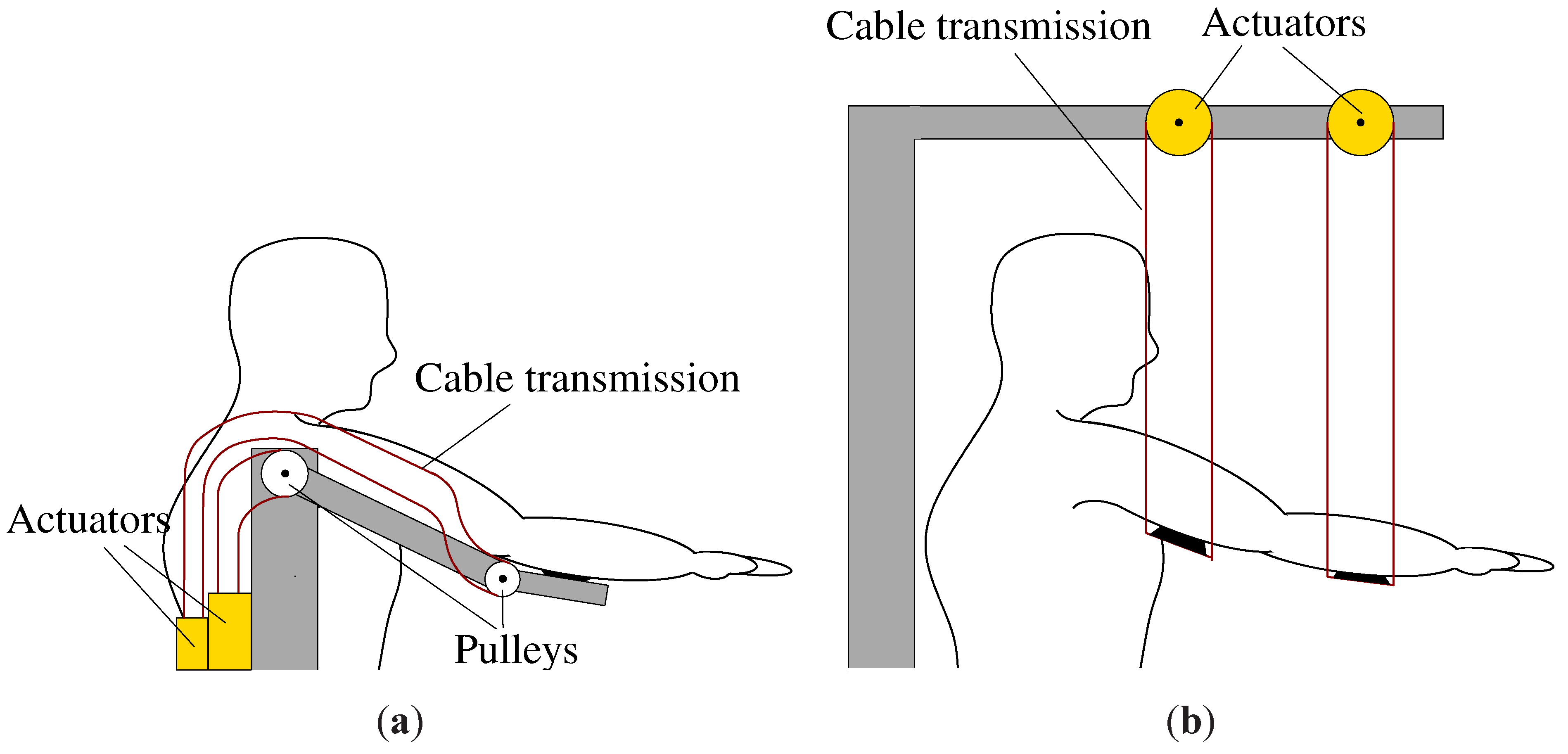
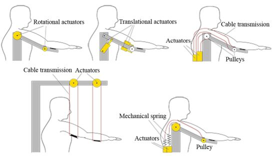
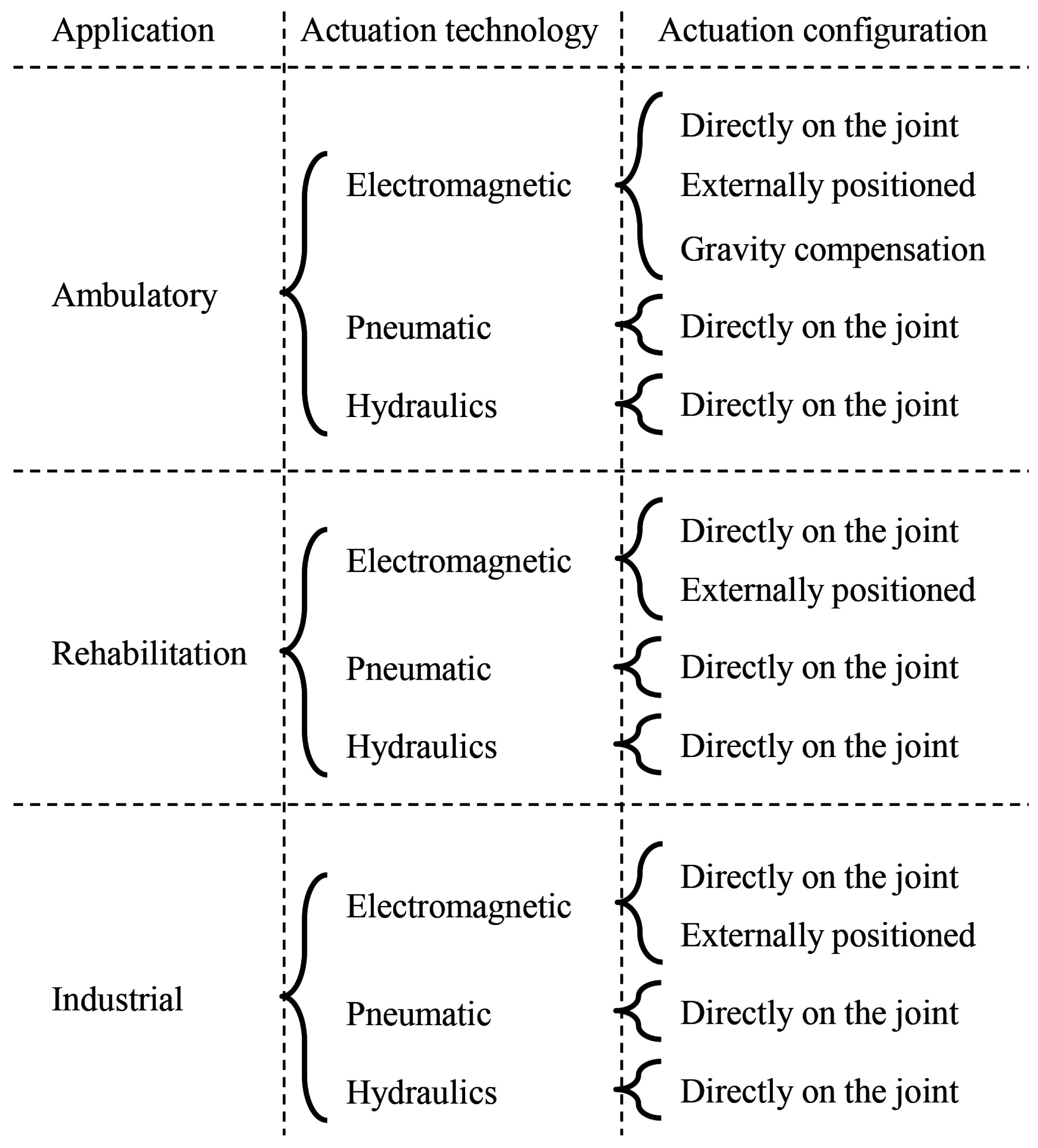
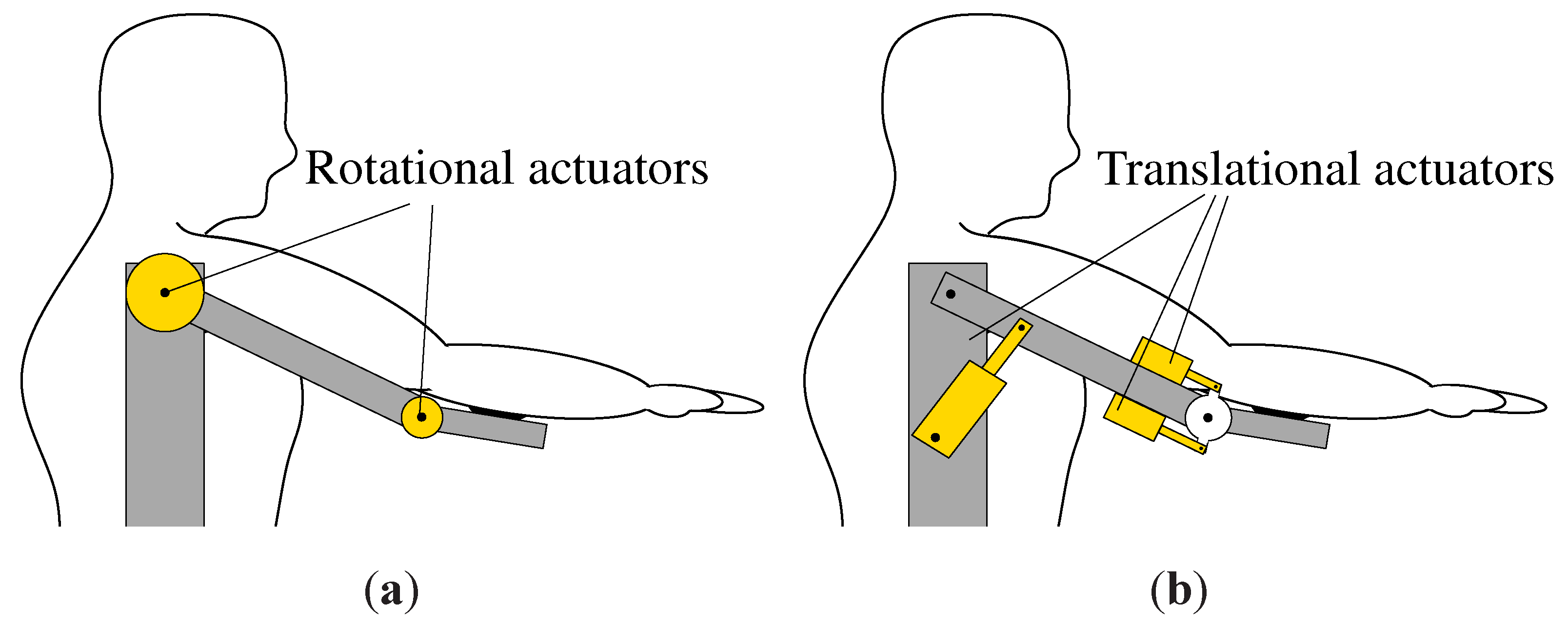
5. Actuator Configuration

The actuator configuration of arm support systems considers the position of the actuators within the mechanical construction. The placement influences not only the functionality, but more importantly for this overview, it influences the possible actuator principles and dimensions that can be applied. Several actuation configurations can be distinguished: directly on the joint, externally positioned, and gravity compensated. Furthermore, the inertia, the actuator bandwidth, the number of DOFs, and the difference between exoskeleton and end effector are considered in this section.

5.1. Configurations

Placing the actuators directly on the joint of the arm support system makes it possible to develop easier and more direct control strategies. A mechanical construction for actuators mounted directly on the joint results in a schematic construction as shown in Figure 2a for rotational actuators and in Figure 2b for translational actuators. Note that both figures consider one DOF in the shoulder joint and one DOF in the elbow joint.
Externally positioned actuators are usually placed on the stationary part of the arm support system and use cable-drive transmissions to transfer a force or torque. Two mechanical structures can be distinguished namely: An exoskeleton design and a cable suspension design. The exoskeletons use cable-drive transmission that follow the human arm as shown in Figure 3a, whereas cable suspension supports the human arm from above as shown in Figure 3b.
Figure 2. Schematic examples of directly on the joint actuation configuration for (a) rotational and (b) translational.
Actuators 02 00086 g002
Figure 3. Schematic examples of external positioned actuation configuration for (a) placed on the stationary part and (b) cable suspended.
Actuators 02 00086 g003
Furthermore, the ROM of all three actuator configurations are comparable except for the cable suspension configuration [55]. Cable suspension can achieve a large ROM with less DOF compared to the other actuation configurations. However, a complete structure covering the user is necessary to achieve this ROM as can be seen in Figure 3b. Designs of cable suspended arm supports are proposed to achieve an optimal ROM [56,57,58].
Passive gravity compensation is realized using a compressed mechanical spring. The tension of this spring can be adjusted by an actuator as shown in Figure 4 to account for extra loading e.g., lifting a cup. Providing a limited number of DOFs compared to the aforementioned arm support systems, this topology provides less functionality compared to the actuated arm supports. However, because they can be designed to be small and inconspicuous, they are popular for AAS systems [59]. Furthermore, these compensators have almost no energy consumption which makes them very suitable to be mounted on electric wheelchairs. The electromagnetic actuator, used to change the tension of the spring, is often controlled by the user [1,60].
Figure 4. Schematic example of adjustable gravity compensation using mechanical springs.
Actuators 02 00086 g004

5.2. Inertia

In general, multi-DOF arm support systems which use directly on the joint actuator configurations have stacked single-DOF actuators. The simplified schematic in Figure 2a shows a 2-DOF arm support systems with stacked actuators. In a stacked configuration, the first actuator (i.e., the shoulder joint actuator) compensates the gravity and inertia of the second actuator (i.e., the elbow joint actuator). When movements only occur in the horizontal plane, the first actuator only requires to account for the inertia of the second actuator. Note that the more DOFs, the more actuators are stacked which results into bulky systems. The number of actuators for multi-DOF arm support systems can be reduced by multi-DOF actuators. For example, in [61] a spherical actuator with three rotational degrees of freedom is proposed to mimic the shoulder joint.
Another solution for the stacked actuator problem is the externally positioned actuation configuration. Placing the actuator externally can decrease the weight of the dynamic part of the arm support with 60% for exoskeleton designs [2]. Additionally, a low-mass structure has less inertia which provides a better dynamical performance. The externally positioned actuation configuration has also several disadvantages, i.e., the cable tension of the cable-drive transmission must be maintained during dynamic behavior [56], friction or even variable friction due to the cables and pulleys, and a complex mechanical design as e.g., cables may not interfere with the user’s movements. Furthermore, cables can only pull and not push.
Finally, a combination of directly on the joint and externally positioned actuation are developed. To create space near the subject’s head an externally positioned configuration is applied while the other actuators are directly positioned on the joint [62]. A combination of the directly on the joint configuration using pneumatic actuators as shown in Figure 2b and the gravity compensation as shown in Figure 4 is proposed in [42]. In this design, the pneumatic actuator is placed in parallel to the mechanical spring; hence, the actuator only has to account for the acceleration and deceleration of the arm support. A combination of pneumatic and electromagnetic actuators is applied [24] because the pneumatic actuators are not powerful enough for four of the five DOFs. For these four DOFs electromagnetic actuators are used.

5.3. Bandwidth

For arm support systems, a control bandwidth is desired in the same range or higher than that of a human. The position control bandwidth of a healthy human depends on the action that is required. For newly introduced actions, the bandwidth is in the range of 1–2 Hz, a repetitive action the bandwidth range is 2–5 Hz, for learned actions a bandwidth of 5 Hz can be obtained and for reflexive actions 10 Hz is reached [63].
Each actuation technology has its own set of specifications and adding additional hardware such as gears and mechanical springs can have a significant impact on the system bandwidth. Electrical actuators have a high force control bandwidth (higher than 100 Hz) that is in general significantly higher than the mechanical resonances of the arm support which can occur around 6–8 Hz [2,28]. Other designs have mechanical resonances around 40 Hz [64].
Pneumatic actuators have a bandwidth in the same range of the mechanical resonances. Using pneumatic muscles, a force control bandwidth of 3.5 Hz was achieved while tracking a 5 cm peak to peak sine wave [42]. The pMA has a position control bandwidth performance of approximately 1.4 Hz [65]. Hence, a limited number of healthy human actions can be performed.
Adding hardware to the actuators can influence the total system performance. Adding a low gear ratio (35:1) to a brushed DC motor limits the mechanical bandwidth to approximately 50 Hz [64]. Placing an electric brushed DC motor in series with a spring with a stiffness of 2.51 Nm/rad resulted in a force control bandwidth of 3.15 Hz [27]. The same holds for rotary hydraulic actuators. A multisine torque bandwidth of 18 Hz can be reached applying a spring stiffness of 150 Nm/rad [35]. A linear hydraulic actuator combined with a series placed mechanical spring which is able to adjust the spring tension, provides a position control bandwidth in the range of 6.5–7.2 Hz [34].

5.4. Degrees of Freedom

The human arm can be simplified by 7 active DOFs, namely: 3 DOFs for the shoulder joint, 1 DOF for the elbow, 1 DOF for the forearm and 2 DOFs for the wrist [53,66,67]. Additionally, active or passive DOF can be added to e.g., provide joint alignment and horizontal movement, although, these DOFs are redundant. Depending on the aim of the arm support, a limited number of DOFs decreases the complexity of the mechanical design and the control strategy [51]. It is not necessary to provide 7 DOFs of support during ADL, for example gravity compensators can have 5 DOFs [1,4,60] (3 DOFs for the shoulder, 1 DOF for the elbow, and 1 DOF for the forearm) or even less [8]. Sometimes, the goal is to provide only 1 DOF, e.g., for tremor suppression [68]. Using passive degrees of freedom some systems go up to 10-DOF systems [26] (7-DOFs for the arm and 3-DOFs for the fingers). Further developments show that even more DOFs are necessary to completely mimic the human arm, such as a 14-DOFs system described in [64] (6 DOFs for the shoulder, 2 DOFs for the elbow, 1 DOF for the forearm, 2 DOFs active and 3 DOFs passive for the wrist).

5.5. Exoskeleton versus End-Effector

The human-machine interaction influences the design of the arm support. Different designs are applied, such as placement of the arm support system behind, aside, or in front of the user, were the most used schematics are shown in Figure 5.
Figure 5. Arm support systems configurations (a) exoskeleton (b) multiple end-effectors (c) end-effector placed behind or aside of the user (d) end-effector placed in front of the user.endEffector2.eps
Actuators 02 00086 g005
The exoskeleton such as arm support systems are attached to the upper arm, forearm and sometimes also the wrist/hand as shown in Figure 5a [2,4,29,34,51,53,56,64,69]. Applying an exoskeleton arm support, the limbs can be controlled accurately. This provides the ability to control the arm movement exactly; hence, it can be beneficial for training. The disadvantage is that the joints of the arm support must be perfectly aligned with the joints. Otherwise, the joints can suffer from wear and tear. Especially the shoulder joint is fragile since it has many DOFs and is easily dislocated.
Instead of using one arm support, multiple supports can be used, e.g., one for each limb as shown in Figure 5b [70,71]. Using multiple robots, one can use low cost commercially available robots; hence, the chance of a commercial success is higher [70,71,72]. However, the resulting arm support systems is cumbersome and bulky. Additionally, haptic devices, such as the HapticMaster, are applied for exploring the possibilities of using virtual reality in rehabilitation [73] and, for assessment of human motor impairments [19].
Providing support at a single point, e.g., at the forearm from the back or aside the user as shown in Figure 5c [1,27,33,42,60] is referred to as end-effector. It is also possible that such end-effector is placed in front of the user and e.g., is controlled by the hand, as shown in Figure 5d [74,75]. End-effectors provide support on one point of the human arm; hence, no joint alignment is required. This simplifies the installation routine and no direct danger of damaging a joint is present. Furthermore, the kinematics do not have to be exactly the same as a human arm. However, the motion of the human arm cannot be controlled accurately.
Some arm support designs only provide support in the horizontal direction, which are referred as planar arm supports, and, therefore, need less powerful actuators (i.e., gravity can be compensated mechanically) [74,76]. Providing support in the vertical direction (i.e., account for the gravity), more powerful actuators are required which results in a more complex mechanical construction. Additionally, the control strategy and kinematics will be more complex. The vertical direction is necessary to provide support and training to an increased number of ADL [54,77].

6. Comparison

In this section a comparison is made between the arm support systems found in the literature. The arm support systems are subdivided according to their application (i.e., user environment), actuation principle and actuation configuration as summarized in Table 1, Table 2 and Table 3. In general, it is found that all arm support systems can be placed in one of these groups, however, some of them can belong to two groups. In this case, the found system is placed in the group with the most comparable actuators based on their size and volume.
Table 1. Overview of the maximum torque/force of the AAS systems.
Actuation TechnologyActuator Configuration T max [Nm] F max [N]SpeedPower [W]ReferencePublication Year
ShoulderElbow
Electromagnetic actuatorsDirectly on the joint2323-48 ° /s19[78]1969
15 a 7.2 a -75 ° /s19.6[51]2001
External positioned9828.4-95 ° /s185 b [79]2008
Gravity compensation--4500[1]2006
--5000[60]2007
PneumaticDirectly on the joint--220 c 1.1m/s242[42]2006
HydraulicDirectly on the joint63.689---[33]2009
a Design specifications; b Catalog specification; c pressure of 600 kPa used.
Table 2. Overview of the maximum torque/force of the RAS systems.
Actuation TechnologyActuator Configuration T max [Nm] F max [N]SpeedPower [W]ReferencePublication Year
ShoulderElbow
Electromagnetic actuatorsDirectly on the joint-28151-150 a [77]2006
--12--[70]2007
20--1146 ° /s400[54]2008
Externally positioned--50-312 a [55]2007
62 b 33 b ---[2]2007
20032-35 ° /s122[62]2008
- 45--[56]2012
PneumaticDirectly on the joint306-64 ° /s c 33.5 c [45]2003
1515-50 ° /s13[44]2007
HydraulicDirectly on the joint-15-469 ° /s c , d 123 c , d [34]2011
a Catalog specified rated power; b Torque based on gear ratio; c Estimated from figure; d A 1.1kW compressor used.
Table 3. Overview of the maximum torque/force of the IAS systems.
Actuation TechnologyActuator Configuration T max [Nm] F max [N]SpeedPower [W]ReferencePublication Year
ShoulderElbow
Electromagnetic actuatorsDirectly on the joint2010---[4]1994
Externally positioned19.34.5- 150 a [64]2011
PneumaticDirectly on the joint- 200 b 10 ° /s-[80]1999
a Catalog specified rated power; b pressure of 400kPa used.
Only arm support systems with clearly stated torque for the shoulder and elbow joint and/or force figures are taken into account. In each category, the developed prototypes are sorted on their publication year. Additionally, only the power and speed of the shoulder joint is considered because this joint requires the highest amount of power. To make a fair comparison, planar arm support systems are excluded from the comparison. Because no torque is needed to compensate for the gravity force; hence, no fair comparison can be made.

6.1. AAS Systems

Inventarisation of the AAS systems results in an overview of the systems as shown in Table 1. From this overview it can be seen that the torque generated by electromagnetic actuators positioned directly on the joint are in the same range namely: 5–25 Nm. The electromagnetic actuators externally positioned utilize a shoulder joint torque that is higher, namely 98 Nm, whereas the elbow joint torque is similar to the electromagnetic actuators positioned directly on the joint (28.4 Nm). Additionally, a difference can be seen in power because of the torque difference and a small speed difference between these configurations in Table 1. The gravity compensation category only specifies a force to indicate the amount of support on the forearm. Therefore, it is difficult to specify the resulting support torque of each joint. It can be seen in Table 1 that the arm support systems, which use gravity compensation, have a comparable force of 45 N and 50 N.
The pneumatic muscles are difficult to compare with the other actuation principles because only the maximum force, which the pneumatic actuator can exert, is mentioned. The amount of this force that is used to support the human arm is not clearly stated. It can be seen that the pneumatic device has the highest power compared to the other actuation configurations. Note that the power of the hydraulic actuator is not provided; hence, it cannot be compared.
The hydraulic actuator which specifies the torques for the shoulder and elbow is the HBSA. This arm support provides an elbow torque that is higher than the shoulder joint torque and it has the highest torque for the elbow compared with the other actuation principles [33]. Unfortunately, no speed or power information is provided; hence, it is unknown if the shoulder or elbow requires the highest amount of power. In general, one expects that the shoulder joint requires the largest amount of torque due to a larger arm length. However, depending on the specified ROM, for example shoulder flexion of 0–20 and an elbow flexion of 0–145 , it is possible that the torque requirement for the shoulder joint is the lowest.

6.2. RAS Systems

In RAS systems, a large variety of actuator configurations exists resulting in a large diversity of force, torque, and power specifications as shown in Table 2. The dedicated RAS device of [77] provides a force of 151 N utilizing a ball screw together with a 150 W electric motor. Applying commercial machines, a maximum force of 12 N can be achieved [70]. Remarkable is the high speed specification of [54] namely 1146 /s, which is by far the highest of all other arm support systems.
The externally positioned electromagnetic actuators have a torque range that varies widely for the shoulder joint, namely 62 Nm-200 Nm, whereas for the elbow joint a torque of 32 Nm is applied. The force range of the cable suspended arm supports [55,56] are both in the same range, namely 45 Nm–50 Nm. Furthermore, the power needed to produce 50 N by [55] is 231 W, whereas the 150 N produced by [77] requires only 150 W. This difference is caused by the used gearing. A pulley was used to convert the torque into a force by [55], whereas a ball screw was used by [77].
The pneumatic actuators are able to provide a torque in the range of 15 Nm–30 Nm for the shoulder joint and 6 Nm–15 Nm for the elbow joint. Note that [44] provides the same torque for the shoulder joint as the elbow joint namely 15 Nm, whereas in [45] a different torque between these two joints is applied, namely 30 Nm for the shoulder joint and 6 Nm for the elbow joint.
The torque provided by the hydraulic actuator (15 Nm) is in a comparable range with the torque generated by the pneumatic actuators. Comparing the power used by the hydraulic actuator and pneumatic actuators, it can be seen that the hydraulic actuator requires more power. This power difference can be explained by the difference in speed.
The pneumatic and hydraulic actuators provide a lower torque compared to the externally positioned electromagnetic actuators, however, they are used because of their large power-to-weight ratio. Exact specifications are unknown for RAS systems, however, some numbers really standout such as the 200 Nm torque used for the shoulder joint actuation [62] and force of 151 N [77]. The force of 151 N can be explained because the majority of this force is necessary to lift the arm support itself, however, the 200 Nm is rarely high where it could be possible that the used actuator is oversized.

6.3. IAS Systems

The IAS systems group is the smallest group of arm support systems compared to the AAS and RAS systems. The IAS systems consists of two types of arm support systems, master/slave devices and for enhancement of the human body. For master/slave devices, only haptic is required such as force feedback. Therefore, the range of 19–20 Nm for the shoulder joint and 4–10 Nm for the elbow joint is sufficient and providing a higher torque only results in more complex and cumbersome constructions.
It is difficult to compare the pneumatic actuators with the electromagnetic actuators because the forces mentioned is what the actuators can exert and not the resulting force on the human arm. These actuators are used providing support to only the elbow [80]. However, it is not directly clear which amount of this force is used to enhance the human arm.

7. Future Trends

Besides the electromagnetic, pneumatic and hydraulic actuators, other actuation principles exist based on piezoelectricity, shape memory alloys, electroactive polymers [81], metal hydrides [82], and polymeric gels.
Piezoelectric actuators use piezoelectric material that changes its shape when a voltage is applied. With this property a stepper actuator can be constructed combining multiple piezoelectric elements. By placing two piezoelectric elements in series, the first can expand to make contact to the surface of the rotor. Subsequently, the second piezoelectric element pushes the rotor into one direction. After retracting both piezoelectric elements this sequence is repeated to create motion. The down-side of piezoelectric motors are their high production costs and difficulty to manufacture [32]. Furthermore, these actuators have a high stiffness.
Shape memory alloys actuators are constructed from special metal alloys such as copper-aluminum-nickel and nickel-titanium that remember their initial cold-forged shape. Heating the actuator causes deformations that produces large forces. When the actuator is cooled it returns to its initial cold-forged shape. This actuator has the property to produce large forces, however, only small displacements can be achieved. Additionally, the bandwidth is very low because it mainly depends on the cooling cycle [32].
Electroactive polymers are polymers that change their size or shape when an voltage is applied. This actuation concept is the most comparable with the McKibben muscle and pMAs. As being very similar to the human muscle, electroactive polymers are often referred to as artificial muscles. The shape will contract when a high voltage is applied. Unfortunately, they are only able to contract. Furthermore, only a small displacement can be achieved [81].
Metal hydride alloys use a reversible chemical reaction using hydrogen gas. By increasing the temperature, the pressure can be increased and vice versa; hence, a force can be generated. A soft metal hydride actuator for in home rehabilitation is proposed by [82], the designed actuator is able to provide a force of 274.4 N. Furthermore, according to the figures, it has a dynamic performance of 0.15 mm/s. This actuation principle has a high force-to-weight ratio compared to electromagnetic actuators, however, it has a relative small stroke and a low speed. Therefore, it is not often applied in arm support systems.
Polymeric gels are solid liquid systems which swell by adding liquids but do not dissolve [83]. Using this swelling property a linear actuator can be constructed that is able to produce a high force density. The disadvantage of this actuator is its low bandwidth [32].
The aforementioned actuation principles can be very promising for the future, however, until they are more conventional, the costs of construction are high compared to the off-shelf actuators that are already used in arm support systems.
In electromagnetic actuators, a clear trend is visible of combining multi-DOF in a single actuator such as planar motion [84], spherical motion [85] and, combined rotary and linear motion [86]. Especially spherical motors are of interest because of their ability to mimic the shoulder joint.
Despite years of research and development on these systems, only a limited number of AAS and RAS systems are commercially available. Examples of AAS are the Armon [1] and the DAS [60] and examples of RAS systems are Armeo, ARMin II, and KINARM [76]. Note that only AAS systems with adjustable gravity compensation are available on the market. Current trends show that more advanced arm support systems are being developed, more control strategies are explored, and recent results show the effects of robot guided therapy [87,88]. An increasing number of countries show interest in the development of arm support systems as is shown in Table 4. It can be seen that the USA together with Japan has the lead with 18 and 12 publications, respectively. The following countries are the UK and The Netherlands with 8 and 6 publications, respectively. The next 15 countries have 4 or less publications. The increasing research of arm support systems is promising for an increase of commercially available arm support systems.
Table 4. The geographic distribution of the first authors from the used references.
Developers LocationReferencesAmount
USA[2,5,11,14,26,27,36,42,44,54,56,59,62,63,72,74,78,89]18
Japan[33,40,41,52,53,66,79,80,82,90,91,92]12
UK[7,32,45,51,58,65,70,73]8
The Netherlands[1,17,19,35,60,64]6
Italy[3,4,34,55]4
Switzerland[6,77,87,93]4
Spain[12,24,94]3
Belgium[48,88]2
Canada[29,76]2
China[31,67]2
New-Zealand[9,95]2
Austria[96]1
Brazil[57]1
France[25]1
Hungary[71]1
Poland[69]1
Romania[22]1
Slovenia[47]1
S. Korea[28]1

8. Conclusions

A technological overview of arm support systems found in the literature has been provided in this paper. The presented arm support systems have been divided based on their applications, actuation technology, and actuator configuration. Three different applications have been distinguished namely, ambulatory, rehabilitation, and industrial. Ambulatory arm support systems are used at home, provide a limited ROM, and are energy efficient. It is intended to compensate for muscle activity or to avoid muscle fatigue. A wide range of rehabilitation arm support systems exists for a wide variety of neurologic lesions and to provide training possibilities. Therefore, more flexibility is required for this application compared to the ambulatory applications. However, mobile rehabilitation arm supports are usually dedicated and, therefore, less flexible. Industrial arm support systems are designed for enhancement of the human body or to function as a master/slave device. For enhancement of the human body, powerful actuators are required, whereas master/slave devices only require haptics.
The actuation principles that are applied in existing arm support systems are electromechanical actuators, pneumatic actuators, hydraulic actuators, and semi-active dampers. These actuation principles are the most popular because of their availability, low costs, and controllability compared to other less known and not off-the-shelf available actuation principles. Furthermore, compliant behavior is important when choosing an actuation technology. Pneumatic actuators are inherently compliant, whereas geared electromagnetic and hydraulic actuators require additional hardware or software. However, pneumatic actuators have a non-linear behavior. Hardware or software solutions such as series elastic actuators or specific control strategies, respectively, can be used to achieve compliance. As compliant actuators are important for comfort and safety, it presents challenges for the arm support system design.
Actuation configuration is the mechanical construction that is controlled by the actuation technology. Externally positioned actuator configurations have a better dynamical behavior compared to the directly on the joint positioned actuator configurations. However, they have a more complex mechanical construction. The external positioned actuation configuration can be subdivided into two groups, exoskeleton constructions and cable suspended constructions. The cable suspended construction has a large range of motion, however, consists usually of a larger mechanical construction compared to the exoskeleton construction. Furthermore, a special actuation configuration can be distinguished which includes the gravity compensators. This actuation configuration is only applied in ambulatory arm support systems and consists of a mechanical spring or counterweight to compensate for the gravity force. The mechanical spring is prestressed and, therefore, this actuation configuration has a very low energy consumption. Furthermore, the tension of this spring can be adjusted with an electromagnetic actuator. However, it has less actuated joints compared to the other actuation configurations.
For each application, different requirements are given and by comparing the arm support systems, an order of magnitude for the torque and power requirements can be deducted. The ambulatory arm support systems have a power range of about 0 W to 242 W, whereas the rehabilitation arm support systems have a power range of about 13 W to 400 W. The industrial arm support systems have actuators with a power of around 150 W for master/slave applications. Depending on the set of requirements, the most suitable actuation technology and actuation configuration can be chosen. An human arm can be simplified into seven degrees of freedom, however, depending on the supporting activities, the number of degrees of freedom can differ. Furthermore, it appeared that the utilized compliant actuators, such as pneumatic actuators and series elastic actuators, have a similar bandwidth of 3 Hz to 18 Hz.
In this technological overview it has been shown that a large variety of arm support systems exist. This variety will grow further, for example, relative new actuation principles (metal hydride alloys) are already applied in arm support systems. Future arm support systems will consist of more complex actuation principles such as multiple degrees of freedom actuators, adjustable compliant actuators, and artificial muscles with a high force control bandwidth. More actuated arm support systems will become commercially available. However, before arm support systems are widely applied, many challenges need to be faced.

Acknowledgements

This work has received funding from the Dutch “Pieken in de Delta" program, project McArm no. PID102055. This program is financed by: Agentschap NL and Provinces Noord-Brabant and Limburg.

Conflict of Interest

The authors declare no conflict of interest.

References

  1. Herder, J.; Vrijlandt, N.; Antonides, T.; Cloosterman, M.; Peter L., M. Principle and design of a mobile arm support for people with muscular weakness. J. Rehabil. Res. Dev. 2006, 43, 591–604. [Google Scholar] [CrossRef] [PubMed]
  2. Perry, J.; Rosen, J.; Burns, S. Upper-limb powered exoskeleton design. Trans. Mechatron. (ASME) 2007, 12, 408–417. [Google Scholar] [CrossRef]
  3. Bergamasco, M.; Salsedo, F.; Marcheschi, S.; Lucchesi, N. A Novel Actuation Module for Wearable Robots. In Advances in Robot Kinematics: Motion in Man and Machine; Springer: Dordrecht, The Netherlands, 2010; pp. 117–125. [Google Scholar]
  4. Bergamasco, M.; Allotta, B.; Bosio, L.; Ferretti, L.; Parrini, G.; Prisco, G.; Salsedo, F.; Sartini, G. An Arm Exoskeleton System for Teleoperation and Virtual Environments Applications. In Proceedings International Conference on Robotics and Automation, San Diego, CA, USA, 8–13 May 1994; Volume 2, pp. 1449–1454.
  5. Reinkensmeyer, D.; Lum, P.; Winters, J. Emerging Technologies for Improving Access to Movement Therapy following Neurologic Injury. In Emerging and Accessible Telecommunications, Information and Healthcare Technologies; RESNA Press: Arlington, VA, USA, 2002. [Google Scholar]
  6. Riener, R.; Nef, T.; Colombo, G. Robot-aided neurorehabilitation of the upper extremities. Med. Biol. Eng. Comput. 2005, 43, 2–10. [Google Scholar] [CrossRef] [PubMed]
  7. Loureiro, R.; Harwin, W.; Nagai, K.; Johnson, M. Advances in upper limb stroke rehabilitation: A technology push. Med. Biol. Eng. Comput. 2011, 49, 1103–1118. [Google Scholar] [CrossRef] [PubMed]
  8. Van der Heide, L.; van Ninhuijs, B.; Bergsma, A.; Gelderblom, G.; van der Pijl, D.; de Witte, L. An overview and categorization of dynamic arm supports for people with decreased arm function. Prosthet. Orthot. Int. 2013, in press. [Google Scholar] [CrossRef] [PubMed]
  9. Lo, H.S.; Xie, S.Q. Exoskeleton robots for upper-limb rehabilitation: State of the art and future prospects. Med. Eng. Phys. 2012, 34, 261–268. [Google Scholar] [CrossRef] [PubMed]
  10. Guizzo, E.; Goldstein, H. The rise of the body bots [robotic exoskeletons]. Spectr. IEEE 2005, 42, 50–56. [Google Scholar] [CrossRef]
  11. Marchal-Crespo, L.; Reinkensmeyer, D.J. Review of control strategies for robotic movement training after neurologic injury. NeuroEng. Rehabil. 2009, 6, 1–15. [Google Scholar] [CrossRef] [PubMed]
  12. Ruiz, A.; Forner-Cordero, A.; Rocon, E.; Pons, J.L. Exoskeletons for Rehabilitation and Motor Control. In Proceedings of the International Conference on Biomedical Robotics and Biomechatronics, (BioRob), Pisa, Italy, 20–22 February 2006; pp. 601–606.
  13. Gopura, R.A.R.C.; Kiguchi, K. Mechanical Designs of Active Upper-limb Exoskeleton Robots: State-of-the-Art and Design Difficulties. In Proceedings of the International Conference on Rehabilitation Robotics, Kyoto, Japan, 23–26 June 2009; pp. 178–187.
  14. Koo, B.; Montes, J.; Gamarnik, V.; Yeager, K.; Marra, J.; Dunaway, S.; Montgomery, M.; de Vivo, D.; Strauss, N.; Konofagou, E.; Kaufmann, P.; Morrison, B. Design and Evaluation of a Hybrid Passive and Active Gravity Neutral Orthosis (GNO). In Proceedings of the International Conference on Engineering in Medicine and Biology Society, Minneapolis, MN, USA, 3–6 September 2009; pp. 1573–1576.
  15. Van der Smagt, P.; Grebenstein, M.; Urbanek, H.; Fligge, N.; Strohmayr, M.; Stillfried, G.; Parrish, J.; Gustus, A. Robotics of human movements. J. Physiol. Paris 2009, 103, 119–132. [Google Scholar] [CrossRef] [PubMed]
  16. Tesar, D. Overview of the long term objectives of the journal actuators. Actuators 2012, 1, 1–11. [Google Scholar] [CrossRef]
  17. Mastenbroek, B.; de Haan, E.; van den Berg, M.; Herder, J. Development of a Mobile Arm Support (Armon): Design Evolution and Preliminary User Experience. In Proceedings of the International Conference on Rehabilitation Robotics, Noordwijk, The Netherlands, 13–15 June 2007; pp. 1114–1120.
  18. MicroGravity. Armon. 2012. Available online: http://www.mginside.eu (accessed on 27 September 2013).
  19. Stienen, A.H.A.; McPherson, J.; Schouten, A.; Dewald, J.P.A. The ACT-4D: A Novel Rehabilitation Robot for the Quantification of Upper Limb Motor Impairments following Brain Injury. In Proceedings of the International Conference on Rehabilitation Robotics, Zurich, Switzerland, 29 June–1 July 2011; pp. 1–6.
  20. Jansen, M.; Burgers, J.; Jannink, M.; van Alfen, N.; de Groot, I.J. Functional deterioration in wheelchair-dependent boys with Duchenne Muscular Dystrophy may be delayed by arm-support and assisted training. Neurorehabil Neural Repair. 2013, in press. [Google Scholar] [CrossRef] [PubMed]
  21. Mehrholz, J.; Platz, T.; Kugler, J.; Pohl, M. Electromechanical and robot-assisted arm training for improving arm function and activities of daily living after stroke. Cochrane Database Syst. Rev. 2008. [Google Scholar] [CrossRef]
  22. Alutei, A.; Vaida, A.; Mandru, D.; Tatar, M. Development of an Active Upper-Limb Orthosis. In Proceedings of the International Conference on Advancements of Medicine and Health Care through Technology, Cluj-Napoca, Romania, 23–26 September 2009; Volume 26, pp. 405–408.
  23. Van Peppen, R.; van der Pijl, D.; Feys, P. Robotgeassisteerde arm revalidatie bij cliënten na een CVA. Wetenschappelijk Tijdschrift voor Ergotherapie 2011, 4, 4–13. [Google Scholar]
  24. Martinez, F.; Retolaza, I.; Pujana-Arrese, A.; Cenitagoya, A.; Basurko, J.; Landaluze, J. Design of a Five Actuated DoF Upper Limb Exoskeleton Oriented to Workplace Help. In Proceedings of the International Conference on Biomedical Robotics and Biomechatronics (BioRob), Scottsdale, AZ, USA, 19–22 October 2008; pp. 169–174.
  25. Detriche, J. Innovations in dismantling robotics. Nuclear Eng. Design 1998, 182, 267–276. [Google Scholar] [CrossRef]
  26. Frey, M.; Johnson, D.; Hollerbach, J. Full-Arm Haptics in an Accessibility Task. In Proceedings of the Symposium on Haptic Interfaces for Virtual Environment And Teleoperator Systems, Reno, NV, USA, 13–14 March 2008; pp. 405–412.
  27. Ragonesi, D.; Agrawal, S.; Sample, W.; Rahman, T. Series Elastic Actuator Control of a Powered Exoskeleton. In Proceedings of the International Conference on Engineering in Medicine and Biology Society (EMBC), Boston, MA, USA, 30 August–3 September 2011; pp. 3515–3518.
  28. Ivanova, G.; Bulavintsev, S.; Ryu, J.H.; Poduraev, J. Development of an Exoskeleton System for Elderly and Disabled People. In Proceedings of the International Conference on Information Science and Applications (ICISA), Jeju Island, South Korea, 26–29 April 2011; pp. 1–7.
  29. Rahman, M.; K-Ouimet, T.; Saad, M.; Kenne, J.P.; Archambault, P. Nonlinear Control of an Upper-limb Exoskelton Robot. In Proceedings of the International Conference on Electronics, Circuits and Systems (ICECS), Beirut, Lebanon, 11–14 December 2011; pp. 772–775.
  30. Maxon Program 2010/2011; Maxon motor: Sachseln, Switzerland.
  31. Xiong, C.; Jiang, X.; Sun, R.; Huang, X.; Xiong, Y. Control methods for exoskeleton rehabilitation robot driven with pneumatic muscles. Ind. Robot Int. J. 2009, 36, 210–220. [Google Scholar] [CrossRef]
  32. Brown, M.; Tsagarakis, N.; Caldwell, D. Exoskeletons for human force augmentation. Ind. Robot Int. J. 2003. [Google Scholar] [CrossRef]
  33. Umemura, A.; Saito, Y.; Fujisaki, K. A Study on Power-assisted Rehabilitation Robot Arms Operated by Patient with Upper Limb Disabilities. In Proceedings of the IEEE International Conference on Rehabilitation Robotics, Kyoto, Japan, 23–26 June 2009; pp. 451–456.
  34. Lenzi, T.; Vitiello, N.; de Rossi, S.M.M.; Roccella, S.; Vecchi, F.; Carrozza, M. NEUROExos: A Variable Impedance Powered Elbow Exoskeleton. In Proceedings of the International Conference on Robotics and Automation, Shanghai, China, 9–13 May 2011; pp. 1419–1426.
  35. Stienen, A.H.A.; Hekman, E.E.G.; ter Braak, H.; Aalsma, A.M.M.; van der Helm, F.C.T.; van der Kooij, H. Design of a rotational hydroelastic actuator for a powered exoskeleton for upper limb rehabilitation. Trans. Biomed. Eng. 2010, 57, 728–735. [Google Scholar] [CrossRef] [PubMed]
  36. Case, D.; Taheri, B.; Richer, E. Design and characterization of a small-scale magnetorheological damper for tremor suppression. Trans. Mechatron. (ASME) 2013. [Google Scholar] [CrossRef]
  37. Paulides, J.J.H.; Encica, L.; Lomonova, E.A.; Vandenput, A.J.A. Design considerations for a semi-active electromagnetic suspension system. Trans. Magn. 2006, 42, 3446–3448. [Google Scholar] [CrossRef]
  38. De Jesus Lozoya-Santos, J.; Tudon-Martinez, J.; Morales-Menendez, R.; Ramirez-Mendoza, R. Comparison of on-off control strategies for a semi-active automotive suspension using HiL. Latin Am. Trans. 2012, 10, 2045–2052. [Google Scholar] [CrossRef]
  39. De Filippi, P.; Tanelli, M.; Corno, M.; Savaresi, S.; Fabbri, L. Semi-active steering damper control in two-wheeled vehicles. Trans. Control Syst. Technol. 2011, 19, 1003–1020. [Google Scholar] [CrossRef]
  40. Haraguchi, M.; Kikuchi, T.; Mihara, M.; Hatakenaka, M.; Miyai, I.; Furusho, J. Development of Evaluation System of the Motor Function for Upper Limbs Using 3-D rehabilitation Robot “EMUL” and Near-infrared Spectroscopy “NIRS”. In Proceedings of the International Conference on Rehabilitation Robotics, Kyoto, Japan, 23–26 June 2009.
  41. Haraguchi, M.; Kikuchi, T.; Jin, Y.; Fukushima, K.; Furusho, J.; Inoue, A.; Oda, K. 3-D Rehabilitation Systems for Upper Limbs Using ER Actuators/Brakes with High Safety: “EMUL”, “Robotherapist” and “PLEMO”. In Proceedings of the International Conference on Artificial Reality and Telexistence, Esbjerg, Denmark, 28–30 November 2007.
  42. Wolbrecht, E.; Leavitt, J.; Reinkensmeyer, D.; Bobrow, J. Control of a Pneumatic Orthosis for Upper Extremity Stroke Rehabilitation. In Proceedings of the International Conference of Engineering in Medicine and Biology Society, New York, NY, USA, 30 August–3 September 2006.
  43. Morales, R.; Badesa, F.; Domenech, L.M.; Garcia-Aracil, N.; Sabater, J.; Menchón, M.; Fernandez, E. Design and Control of a Rehabilitation Robot Driven by Pneumatic Swivel Modules. In Proceedings of the International Conference on Biomedical Robotics and Biomechatronics (BioRob), Tokyo, Japan, 26–29 Sept. 2010; pp. 566–571.
  44. Sugar, T.; He, J.; Koeneman, E.; Koeneman, J.; Herman, R.; Huang, H.; Schultz, R.; Herring, D.; Wanberg, J.; Balasubramanian, S.; Swenson, P.; Ward, J. Design and Control of RUPERT: A Device for Robotic Upper Extremity Repetitive Therapy. IEEE Trans. Neural Syst. Rehabil. Eng. 2007, 15, 336–346. [Google Scholar] [CrossRef] [PubMed]
  45. Tsagarakis, N.G.; Caldwell, D.G. Development and control of a soft-actuated exoskeleton for use in physiotherapy and training. Auton. Robot. 2003, 15, 21–33. [Google Scholar] [CrossRef]
  46. Zanis, R.; Motoasca, E.; Lomonova, E.A. Trade-offs in the Implementation of Rigid and Intrinsically Compliant Actuators in Biorobotic Applications. In Proceedings of the International Conference on Biomedical Robotics and Biomechatronics (BioRob), Rome, Italy, 24–27 2012; pp. 100–105.
  47. Oblak, J.; Cikajlo, I.; Matjai, Z. Haptic Robot for Arm and Wrist Rehabilitation. In IFMBE Proceedings of the World Congress on Medical Physics and Biomedical Engineering, Munich, Germany, 7–12 September 2009; pp. 20–23.
  48. Vanderniepen, I.; van Ham, R.; van Damme, M.; Lefeber, D. Design of a Powered Elbow Orthosis for Orthopaedic Rehabilitation Using Compliant Actuation. In Proceedings of the International Conference on Biomedical Robotics and Biomechatronics (BioRob), Scotsdale, AZ, USA, 19–22 October 2008; pp. 801–806.
  49. Visser, L.; Carloni, R.; Stramigioli, S. Energy-efficient variable stiffness actuators. IEEE Trans. Robot. 2011, 27, 865–875. [Google Scholar] [CrossRef]
  50. Stienen, A.H.A.; Hekman, E.E.G.; Kooij, H.; Ellis, M.D.; Dewald, J.P.A. Aspects of Weight-Support Mechanisms in Rehabilitation Robotics. In IFMBE Proceedings of the World Congress on Medical Physics and Biomedical Engineering, Munich, Germany, 7–12 September 2009; pp. 392–394.
  51. Johnson, G.; Carus, D.; Parrini, G.; Scattereggia Marchese, S.; Valeggi, R. The design of a five-degree-of-freedom powered orthosis for the upper limb. Proc. Inst. Mechan. Eng. Part H: J. Eng. Med. 2001, 215, 275–284. [Google Scholar] [CrossRef]
  52. Gopura, R.A.R.C.; Kiguchi, K.; Li, Y. SUEFUL-7: A 7DOF Upper-limb Exoskeleton Robot with Muscle-Model-Oriented EMG-Based Control. In Proceedings of the International Conference on Intelligent Robots and Systems, St. Louis, MO, USA, 10–15 October 2009; pp. 1126–1131.
  53. Hayashi, Y.; Dubey, R.; Kiguchi, K. Torque Optimization for a 7DOF Upper-limb Power-assist Exoskeleton Robot. In Proceedings of the Workshop on Robotic Intelligence In Informationally Structured Spacecarignan (RiiSS), Paris, France, 11–15 April 2011; pp. 49–54.
  54. Carignan, C.; Naylor, M.; Roderick, S. Controlling Shoulder Impedance in a Rehabilitation Arm Exoskeleton. In Proceedings of the International Conference on Robotics and Automation, Pasadena, CA, USA, 19–23 May 2008; pp. 2453–2458.
  55. Rosati, G.; Gallina, P.; Masiero, S. Design, implementation and clinical tests of a wire-based robot for neurorehabilitation. Trans. Neural Syst. Rehabil. Eng. 2007, 15, 560–569. [Google Scholar] [CrossRef] [PubMed]
  56. Mao, Y.; Agrawal, S. Transition from Mechanical Arm to Human Arm with CAREX: A Cable Driven ARm EXoskeleton (CAREX) for Neural Rehabilitation. In Proceedings of the International Conference on Robotics and Automation, Saint Paul, MO, USA, 14–18 May 2012; pp. 2457–2462.
  57. Nunes, W.; Rodrigues, L.; Oliveira, L.; Ribeiro, J.; Carvalho, J.; Goncalves, R.S. Cable-based Parallel Manipulator for Rehabilitation of Shoulder and Elbow Movements. In Proceedings of the International Conference on Rehabilitation Robotics, Zurich, Germany, 29 June-1 July 2011.
  58. Loureiro, R.; Smith, T. Design of the ROBIN System: Whole-arm Multi-model Sensorimotor Environment for the Rehabilitation of Brain Injuries While Sitting or Standing. In Proceedings of the International Conference on Rehabilitation Robotics (ICORR), Zurich, Germany, 29 June–1 July 2011.
  59. Benjuya, N.; Kenney, S. Hybrid arm orthosis. J. Prosthet. Orthot. 1990, 2, 155–163. [Google Scholar] [CrossRef]
  60. Kramer, G.; Romer, G.; Stuyt, H. Design of a Dynamic Arm Support (DAS) for Gravity Compensation. In Proceedings of the International Conference on Rehabilitation Robotics, Noodwijk, The Netherlands, 13–15 June 2007; pp. 1042–1048.
  61. Van Ninhuijs, B.; Motoasca, T.; Gysen, B.; Lomonova, E.A. Modeling of spherical magnet arrays using the magnetic charge model. IEEE Trans. Magn. 2012, 49, 4109–4112. [Google Scholar] [CrossRef]
  62. Park, H.S.; Ren, Y.; Zhang, L.Q. IntelliArm: An Exoskeleton for Diagnosis and Treatment of Patients with Neurological Impairments. In Proceedings of the International Conference on Biomedical Robotics and Biomechatronics (BioRob), Scottsdale, AZ, USA, 19–22 October 2008; pp. 109–114.
  63. Brooks, T. Telerobotic Response Requirements. In Proceedings of the International Conference on Systems, Man and Cybernetics, Los Angeles, CA, USA, 4–7 November 1990; pp. 113–120.
  64. Schiele, A.; Hirzinger, G. A New Generation of Ergonomic Exoskeletons–The High-Performance X-Arm-2 for Space Robotics Telepresence. In Proceedings of the International Conference on Intelligent Robots and Systems, San Francisco, CA, USA, 25–30 September 2011; pp. 2158–2165.
  65. Case, D.; Taheri, B.; Richer, E. Biomimetic actuators in prosthetic and rehabilitation applications. Technol. Health Care 2002, 10, 107–120. [Google Scholar]
  66. Nakai, A.; Ohashi, T.; Hashimoto, H. 7 DOF Arm Type Haptic Interface for Teleoperation and Virtual Reality Systems. In Proceedings of the International Conference on Intelligent Robots and Systems, Victoria, TX, USA, 13–17 October 1998; Volume 2, pp. 1266–1271.
  67. Chou, W.; Wang, T.; Xiao, J. Haptic Interaction with Virtual Environment Using an Arm Type Exoskeleton Device. In Proceedings of the International Conference on Robotics and Automation, New Orleans, LA, USA, 26 April–1 May 2004; Volume 2, pp. 1992–1997.
  68. Seki, M.; Matsumoto, Y.; Iijima, H.; Ando, T.; Kobayashi, Y.; Fujie, M.; Nagaoka, M. Development of Robotic Upper Limb Orthosis with Tremor Suppressiblity and Elbow Joint Movability. In Proceedings of the International Conference on Systems, Man, and Cybernetics, Anchorage, AK, USA, 9–12 October 2011; pp. 729–735.
  69. Gmerek, A. The Virtual Reality System Used for Upper Extremity Rehabilitation. In Proceedings of the International Conference on Methods and Models in Automation and Robotics, Miedzyzdrojie, Poland, 27–30 August 2012.
  70. Jackson, A.; Culmer, P.; Makower, S.; Levesley, M.; Richardson, R.; Cozens, A.; Williams, M.; Bhakta, B. Initial Patient Testing of iPAM–a Robotic System for Stroke Rehabilitation. In Proceedings of the International Conference on Rehabilitation Robotics, Noordwijk, The Netherlands, 13–15 June 2007; pp. 250–256.
  71. Toth, A.; Fazekas, G.; Arz, G.; Jurak, M.; Horvath, M. Passive Robotic Movement Therapy of the Spastic Hemiparetic Arm with REHAROB: Report of the First Clinical Test and the Follow-up System Improvement. In Proceedings of the International Conference on Rehabilitation Robotics, Chicago, IL, USA, 28 June–1 July 2005; pp. 127–130.
  72. Rahman, T.; Ramanathan, R.; Stroud, S.; Sample, W.; Seliktar, R.; Harwin, W.; Alexander, M.; Scavina, M. Towards the control of a powered orthosis for people with muscular dystrophy. Proc. Inst. Mech. Eng. Part H: J. Eng. Med. 2001, 215, 267–274. [Google Scholar] [CrossRef]
  73. Loureiro, R.; Amirabdollahian, F.; Topping, M.; Driessen, B.; Harwin, W. Upper limb robot mediated stroke therapy–GENTLE/s approach. Auton. Robot. 2003, 15, 35–51. [Google Scholar] [CrossRef]
  74. Krebs, H.; Hogan, N.; Aisen, M.; Volpe, B. Robot-aided neurorehabilitation. Trans. Rehabil. Eng. 1998, 6, 75–87. [Google Scholar] [CrossRef]
  75. Artemiadis, P.; Kyriakopoulos, K. EMG-based Position and Force Control of a Robot Arm: Application to Teleoperation and Orthosis. In Proceedings of the International Conference on Advanced Intelligent Mechatronics, Zurich, Switzerland, 4–7 September 2007.
  76. Ball, S.; Brown, I.; Scott, S. Performance evaluation of a planar 3DOF robotic exoskeleton for motor assessment. J. Med. Devices 2009. [Google Scholar] [CrossRef]
  77. Nef, T.; Mihelj, M.; Colombo, G.; Riener, R. ARMin—Robot for Rehabilitation of the Upper Extremities. In Proceedings of the International Conference on Robotics and Automation, Orlando, FL, USA, 15–19 May 2006; pp. 3152–3157.
  78. Nickel, V.; Kachak, J.; Allen, J. Electrically powered orthotic systems. J. Bone Joint Surg. 1969, 51-A, 343–351. [Google Scholar] [CrossRef] [PubMed]
  79. Gopura, R.; Kiguchi, K. Development of a 6DOF Exoskeleton Robot for Human Upper-Limb Motion Assist. In Proceedings of the International Conference on Information and Automation for Sustainability (ICIAFS), Colombo, Sri Lanka, 12–14 December 2008; pp. 13–18.
  80. Umetani, Y.; Yamada, Y.; Morizono, T.; Yoshida, T.; Aoki, S. “Skil Mate” Wearable Exoskeleton Robot. In Proceedings International Conference on Systems, Man, and Cybernetics (SMC), Tokyo, Japan, 12–15 October 1999; Volume 4, pp. 984–988.
  81. Kovacs, G.; Lochmatter, P.; Wissler, M. An arm wrestling robot driven by dielectric elastomer actuators. Smart Mater. Struct. 2007. [Google Scholar] [CrossRef]
  82. Ino, S.; Sato, M.; Hosono, M.; Izumi, T. Development of a soft metal hydride actuator using a laminate bellows for rehabilitation systems. Sens. Actuators B: Chem. 2009, 136, 86–91. [Google Scholar] [CrossRef]
  83. Jagur-Grodzinski, J. Polymeric gels and hydrogels for biomedical and pharmaceutical applications. Polym. Adv. Technol. 2010, 21, 27–47. [Google Scholar] [CrossRef]
  84. Jansen, J.W.; van Lierop, C.M.M.; Lomonova, E.A.; Vandenput, A.J.A. Magnetically levitated planar actuator with moving magnets. Trans. Ind. Appl. 2008, 44, 1108–1115. [Google Scholar] [CrossRef]
  85. Yan, L.; Chen, I.M.; Yang, G.; Lee, K.M. Analytical and experimental investigation on the magnetic field and torque of a permanent magnet spherical actuator. Trans. Mechatron. (ASME) 2006, 11, 409–419. [Google Scholar]
  86. Meessen, K.; Paulides, J.J.H.; Lomonova, E.A. Analysis of a novel magnetization pattern for 2-DoF rotary-linear actuators. Trans. Magn. 2012, 48, 3867–3870. [Google Scholar] [CrossRef]
  87. Staubli, P.; Nef, T.; Klamroth-Marganska, V.; Riener, R. Effects of intersive arm training with the rehabilitation robot ARMin II in chronic stroke patients: Four single-cases. J. NeuroEng. Rehabil. 2009. [Google Scholar] [CrossRef] [PubMed] [Green Version]
  88. Gijbels, D.; Lamers, I.; Kerkhofs, L.; Alders, G.; Kinppenberg, E.; Feys, P. The Armeo Spring as training tool to improve upper limb functionality in multiple sclerosis: A pilot study. J. NeuroEng. Rehabil. 2011. [Google Scholar] [CrossRef] [PubMed]
  89. Park, Y.L.; Rong Chen, B.; Majidi, C.; Wood, R.; Nagpal, R.; Goldfield, E. Active Modular Elastomer Sleeve for Soft Wearable Assistance Robots. In Proceedings of the International Conference on Intelligent Robots and Systems (IROS), Vilamoura, Portugal, 7–12 October 2012.
  90. Nagai, K.; Nakanishi, I.; Hanafusa, H.; Kawamura, S.; Makikawa, M.; Tejima, N. Development of an 8 DOF Robotic Orthosis for Assisting Human Upper Limb Motion. In Proceedings International Conference on Robotics and Automation, Leuven, Belgium, 16–20 May 1998; Volume 4, pp. 3486–3491.
  91. Kobayashi, H.; Uchimura, A.; Shiiba, T. Development on Muscle Suit: Realization of Abduction Motion. In Proceedings of the International Conference on Advanced Intelligent Mechatronics (AIM), Kobe, Japan, 20–24 July 2003.
  92. Kobayashi, H.; Hiramatsu, K. Development of Muscle Suit for Upper Limb. In Proceedings of the International Conference on Robotics and Automation, New Orleans, LA, USA, 26 April–1 May 2004.
  93. Staubli, P.; Nef, T.; Klamroth-Marganska, V.; Riener, R. Effects of intensive arm training with the rehabilitation robot ARMin II in chronic stroke patients: Four single-cases. J. Neuroeng. Rehabil. 2009. [Google Scholar] [CrossRef] [PubMed] [Green Version]
  94. Rocon, E.; Belda-Lois, J.; Ruiz, A.; Manto, M.; Moreno, J.; Pons, J. Design and validation of a rehabilitation robotic exoskeleton for tremor assessment and suppression. Trans. Neural Syst. Rehabil. Eng. 2007, 15, 367–378. [Google Scholar] [CrossRef] [PubMed] [Green Version]
  95. Wong, C.K.; Jordan, K.; King, M. Robotic Arm Skate for Stroke Rehabilitation. In Proceedings of the International Conference on Rehabilitation Robotics, Zurich, Switzerland, 29 June–1 July 2011.
  96. Mayr, A.; Kofler, M.; Saltuari, L. An electromechanical robot for upper limb training following stroke. A prospective randomised controlled pilot study. Handchir. Mikrochir. Plast Chir. 2008, 40, 66–73. [Google Scholar] [CrossRef] [PubMed]

