Article

Actuator Location and Voltages Optimization for Shape Control of Smart Beams Using Genetic Algorithms

1
Department of Accounting and Finance, Technological Educational Institution of Epirus, TEI Campus−Psathaki, GR-48100 Preveza, Greece
2
Department of Materials Science and Engineering, University of Ioannina, GR−45110 Ioannina, Greece
3
Department of Production Engineering and Management, Technical University of Crete, Institute of Computational Mechanics and Optimization University Campus, GR−73100 Chania, Greece
*
Author to whom correspondence should be addressed.
Actuators 2013, 2(4), 111-128; https://doi.org/10.3390/act2040111
Submission received: 28 August 2013 / Revised: 23 September 2013 / Accepted: 12 October 2013 / Published: 22 October 2013

Abstract

:
This paper presents a numerical study on optimal voltages and optimal placement of piezoelectric actuators for shape control of beam structures. A finite element model, based on Timoshenko beam theory, is developed to characterize the behavior of the structure and the actuators. This model accounted for the electromechanical coupling in the entire beam structure, due to the fact that the piezoelectric layers are treated as constituent parts of the entire structural system. A hybrid scheme is presented based on great deluge and genetic algorithm. The hybrid algorithm is implemented to calculate the optimal locations and optimal values of voltages, applied to the piezoelectric actuators glued in the structure, which minimize the error between the achieved and the desired shape. Results from numerical simulations demonstrate the capabilities and efficiency of the developed optimization algorithm in both clamped−free and clamped−clamped beam problems are presented.

Graphical Abstract

1. Introduction

Smart or adaptive structures with integrated self−monitoring and control capabilities are of great technological interest due to the increasing requirements on structural performance. The self−monitoring capability of smart structures has numerous applications in shape and vibration control of structures, noise reduction, damage identification, and structural “health” monitoring. Notable references among others are [1,2].
Piezoelectrics are the most popular smart materials, which can be used both as sensors and actuators. The coupled electromechanical properties of piezoelectric materials, along with their possibility to be integrated in various structures, make them suitable for use in advanced smart structures.
The recent advances in smart structures have prompted interest in modification and correction of the shape of mechanical structures, e.g., for the correction of the shape and curvature of mirrors/antennas for high pointing accuracy or for maintaining desired shapes of aerospace flexible structures, etc. The review article by Irschik [3] describes relevant applications of static and dynamic shape control of structures by piezoelectric actuation.
One main objective of piezoelectric shape control is to optimize some control parameters (e.g., the number, location and size of the piezoelectric patches, the amount of electric potential to be applied, etc.) so that the desired shapes are achieved or best matched. Optimization of such parameters and configurations of piezoelectric actuators for acquiring efficient and precise shape control has been an interesting subject of research in recent years. Tong et al. [4] used classical mathematical programming methods for determining the optimal layout of actuators. Agrawal et al. [5] employed the simplex search algorithm to find the optimal actuator locations and voltages, and found that separately optimizing actuator locations and voltages could produce reliable results. Chee et al. [6] presented a heuristic and intuitive algorithm for determining the orientation of piezoelectric actuator patches in shape control of smart structures. Onoda et al. [7] used a modified genetic algorithm (GA) and the improved simulated annealing algorithm for optimal location of actuators in shape control of space trusses. A systematic and general methodology, using a finite element code and genetic algorithms, for the shape control and/or correction of static deformations of adaptive structures, was proposed and verified experimentally by Silva et al. [8]. Hadjigeorgiou et al. [9] investigated the shape control and damage identification of a cantilever composite beam using a genetic optimization procedure. A comprehensive review until 2003, of the design methodologies and application of formal optimization methods to the design of smart structures and actuators can also be found in [10].
In this work, the use of piezoelectric actuators for shape control and correction of static deformations is considered. The models widely used for this kind of problems are based on the Euler beam theory and the Kirchhoff−Love theory of plates with or without electromechanical coupling (e.g., [11,12]). These are considered to be classical models, suitable for thin elastic structures. An extension based on Timoshenko theory and on induced strain actuation theory has been presented by Hadjigeorgiou et al. [9], which is suitable for relatively thick structures. In this work, a mathematical model, based on the shear deformation theory, which incorporates the electro-mechanical coupling effects, has been developed to characterize the behavior of the structure and the actuators. The mathematical model represents an improvement over the model presented in [9]. More precisely, this model accounted for the electromechanical coupling in the entire beam structure, due to the fact that the piezoelectric layers are treated as constituent parts of the entire structural system. In addition, the mathematical formulation models laminated composite beam structures, in which the piezoelectric material may be located anywhere within the structure. This formulation is then implemented into a finite element program.
Besides establishing an accurate mathematical model for shape control applications, a critical factor for the success and performance of the smart structure is the determination of the optimal location of the piezoelectric actuators together with the optimal actuation voltages. Next, the finite element model developed is used in static shape control. Shape control (SC) is defined here as the determination of the applied voltages of actuators and their layout, such that the structure that is activated using these parameters will conform as closely as possible to the desired shape. The problem is formulated as mixed discrete−continuous programming with a quadratic cost function as objective. A genetic algorithm is used as the optimization technique.
Genetic algorithms (GAs) is a well known optimization method [13] that belongs to the general class of evolutionary computation [14], which relies on the premise that in a controlled population the individuals having better traits will finally stand out. Given that in the actuator placement problem a chromosome encoding capable of capturing a solution is relatively straightforward to construct, GAs seems to be a natural way to confront the problem. However, GA based optimization approaches have some issues such as speed of execution, proof of optimality and others that have to be addressed in order to be successfully applied. In our approach, a number of simulations have been performed in order to validate the efficiency of the developed GA based optimization algorithm in both clamped−free and clamped−clamped beam problems.

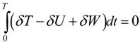
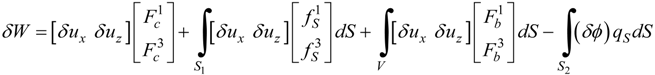
2. Formulation of the Problem

Consider a laminate formed from two or more layers bonded together to act as a single layer material and sandwiched between two piezoelectric layers. The bond between two layers is assumed to be perfect, so that the displacements remain continuous across the bond. The classical formulation of laminated materials is followed [15] and complemented with electromechanical coupling terms. The whole continuum has length L, thickness h and width b. The longitudinal and thickness axes are along x− and z−directions, respectively and the xy−plane is the midplane of the beam. The piezoelectric layers have poling direction along z−axis and the electric field is applied through the thickness direction. Elastic layers are assumed to be insulated and are obtained by annulling the piezoelectric constants.

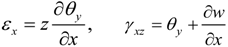
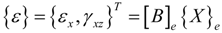
2.1. Strains and Electrical Fields

For a laminated beam with midplane symmetry, the displacement field, using the first−order deformation theory, is expressed as functions of two independent nodal degree of freedom of the middle axis, w and θy, as:
ux (x,y,z) ≈ y (x,t), uy (x,y,z) ≈ 0, uz (x,y,z) ≈ w(x,t)
where w is the transverse displacement of the beam middle axis and θy is the rotation of the beam cross section about the positive y−axis. Assuming small deformation, the strain−displacement relation can be expressed as:
Actuators 02 00111 i001
A constant transverse electrical field is assumed for the piezoelectric layers and the remaining in−plane components are supposed to vanish. Consequently, the electric field inside the pk−th piezoelectric layer is given by
{E}k = −[Bϕ]ϕPk
where
Actuators 02 00111 i002
and hPk ,ϕPk are the thickness and the electric voltage of the pk−th piezoelectric layer. It should be noted that such formulation gives one electric degree of freedom per layer per element of the electric field.

2.2. Constitutive Equations

The linear constitutive equations coupling the elastic and the electric fields in a piezoelectric medium are expressed by the direct and the converse piezoelectric equations, which are given as follows:
Actuators 02 00111 i003
where {σ} is the stress tensor, {ε} is the strain tensor, {D} is the electric displacement, {E} is the electric field, [C] is the elastic stiffness matrix, [e] is the piezoelectric constant matrix, and Actuators 02 00111 i024 is the permittivity matrix. For non−piezoelectric layers, [e] and Actuators 02 00111 i024 are reduced to zero matrices. The constitutive relations, given in Equation (4), are with reference to the global coordinate system (x, y, z).
For a one−dimensional beam where the width in the y−direction is stress free and by using the plane stress assumption, the general 3D constitutive Equation (4) can be reduced to:
Actuators 02 00111 i004
where Q11, Q55 are the transformed plane stress−reduced stiffness coefficients, e31, e32 are the transformed piezoelectric moduli given in [15] and Actuators 02 00111 i025 
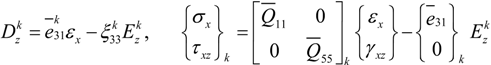
is the electric permittivity.

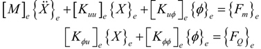
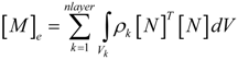
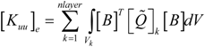
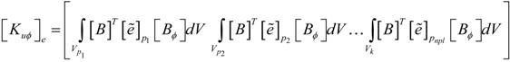
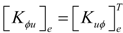
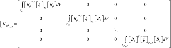
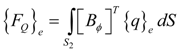
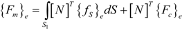
2.3. Finite Element Formulation

To derive the equations of motion for the laminated composite beam with surface bonded sensor and actuator layers, Hamilton’s principle is used:
Actuators 02 00111 i005
The kinetic energy, the potential energy and the total work done due to virtual displacements are given as follows:
Actuators 02 00111 i006
Actuators 02 00111 i007
where {Fc} is the concentrated force vector, {fS} is the surface force vector, {Fb} is the body force vector, {q} is the surface charge vector, S1 is the surface area where external force is acting, and S2 is the surface area of piezoelectric layer where applied electric charge is acting.
A two−node finite element is considered with two mechanical degrees of freedom, w and θy, per node and one additional degree of freedom, ϕ, per piezoelectric layer. Using standard discretization techniques,
Actuators 02 00111 i008
where {X}e = {w1, θy1, w2, θy2}T, [Nw] is a cubic shape function and [Nθ] is a quadratic shape function. These shape functions lead to a shear−locking free element and their explicit expressions are given in Ref. [9]. The strain field is given by:
Actuators 02 00111 i009
where [B]e is the derivative operator between the corresponding strain and the generalized nodal displacements. The electric voltage vector of the eth element can be expressed as:
Actuators 02 00111 i010
where npl is the number of the piezoelectric layers of the eth element.
Using the variational principle, given by Equation (6), governing equations of an element can be written as:
Actuators 02 00111 i011
where the mass matrix [M]e, the elastic stiffness matrix [Kuu]e, the electromechanical coupling matrix [K]e, the permittivity matrix [Kϕϕ]e, the surface electric charge density {FQ}e and the mechanical load vector {Fm}e are given in the Appendix.
The global equations can be obtained by assembling the elemental Equation (12). Equation (12) can be used in smart structures applications such as vibration control, static or dynamic shape control, etc. In shape control applications, which is the case in the present study, the piezoelectric layers are used as actuators. Thus, all the electrical degrees are considered as known quantities and the coupled Equation (12) reduce to pure mechanical ones:
[Kuu]{X} = {Fm} − {Fel}
where [Kuu] ∈ RN×N is the global stiffness matrix, {X} ∈ RN×1 is the nodal displacement vector, {Fm} ∈ RN×1 is the mechanical force vector and {Fel} = [K]{ϕ} is the electrical force vector due to the actuation.
A computer code is developed, based on the aforementioned finite element model. A special numbering scheme is used to denote the elements with piezoelectric layers. Elements with piezoelectric layers are denoted by 1, while the remaining layers are denoted by 0 for the identification during the assembly process.

3. Optimal Shape Control

The most general problem of SC of smart structures considers as design variables the applied voltages of actuators, their layout and their number. The aim is to find the optimal design values so that the difference between achieved and desired shape is minimized. In essence, SC is an inverse problem where the output, which is the desired shape, is known and the input actuation parameters are to be determined. Therefore, iterative heuristic methods are quite suitable to this task. In this work, this problem is solved by a hybrid genetic algorithm.

3.1. The Fitness Function

Considering beam element, the shape of a structure is primarily described by the shape of its middle axis, which itself is described by the transverse displacement of the finite element mesh nodes. Therefore, a reasonable cost function is f1, as given by Equation (14), which is the sum of all the squared difference of the transverse displacements between the desired (pre−defined) and the achieved (calculated) shape at all nodes.
Actuators 02 00111 i012
In the above equation, Actuators 02 00111 i013 
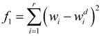
is the desired nodal transverse displacement value and r is the number of concerned displacements.
However, the static shape control criteria in [9] is based on the generalized displacements; that is, on both transverse displacements w and θy rotations . Therefore, a fitness function based on the following cost function is used in the aforementioned paper:
Actuators 02 00111 i014
It should be noted that the simultaneous usage of displacements and rotations in the cost function f2 is very restricted for bending problems such as the ones studied here. Nevertheless, in this work, the two above fitness functions will be used for comparison reasons. Results obtained by using f1 as the fitness function will show improvements over f2. In following, a general symbol f is used to denote any fitness function.

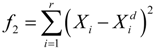
3.2. Design Optimization Problems

In general the displacement field is a function of the electric potential, the layout, the geometry of actuators and the number of actuators. In this framework, two kinds of shape control (SC) problems of a beam with various boundary conditions are studied. The Voltage Problem and the Location and Voltage Problem.
The first SC problem (the Voltage Problem) consists in finding a set of actuation voltages ϕi for a given number and position of actuators, which minimizes the cost function f under the constraint:
ϕminϕiϕmax
where ϕi is the actuation voltage of the ith actuator and ϕmin and ϕmax the lower and upper saturation voltages. In this work, this problem is solved by genetic algorithms. The MatLab software package was used for the development of an algorithm to optimize actuator placement and voltage for a given cost function and for given number of actuators and beam dimensions and properties. The computer code developed makes no assumption of linearity between the displacements and the electric voltages, thus, it can be used for non−linear models as well.
The second SC problem (the Location and Voltage Problem) is more general. It consists in finding the optimal position and electric potential simultaneously for a given number of actuators, which minimize the cost function f. In this problem, it is assumed that every actuator covers exactly the length of one element. The actuator position is modeled using a Boolean type discrete variable for each element and the electric potential of the actuator using a bounded continuous variable. The Mixed Integer Problem that arises is highly nonlinear and is solved using a modified genetic algorithm procedure in order to accommodate two different types of information: the location of each piezoelectric element and the voltage needed to apply to each of them.

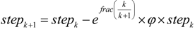
3.3. Genetic Algorithm and Great Deluge

Genetic Algorithms (GAs) are a category of heuristic optimization algorithms that mimics the way traits pass from parents to offspring resulting in the development of characteristics that give an evolutionary advantage to certain members of the population. GAs are an established method of non exact optimization, meaning that a GA is usually able to find very good solutions to hard combinatorial optimization problems when it is difficult or even impossible for an exact optimization method like Linear or Integer Programming to address the same problem within reasonable solving time. A detailed treatment of GAs can be consulted in [13] while successful applications of GAs can be found in almost every field [16]. As GAs is a kind of simulation a great number of function evaluations are required. For this reason, several ways have been proposed so as to speed up the process yet maintain quality of the acquired solutions. With this approach the GA is combined with the Great Deluge method, which creates a part of the initial population consisting of good, yet diverse solutions that are then fed to the GA. The rest of the initial population gets generated using random values. The choice of introducing individuals of relative high fitness early in the optimization process seems to help the GA on finding even higher quality solutions faster.
Great Deluge Algorithm (GDA) is a local search optimization method, which was initially proposed by Dueck [17]. It belongs to the general class of trajectory (single point) search methods for the reason that a single solution is continuously modified so as to progressively achieve better results. Other meta−heuristics that belong to the same class are Simulated Annealing, Taboo Search, Late Acceptance Hill Climbing, and Greedy Randomized Adaptive Search, to name a few. In GDA better solutions are always accepted while worse solutions are also accepted, provided that the computed cost is no worse than the cost of the current solution plus an artificial limit that gradually diminishes. The name Great Deluge was chosen in order to draw an analogy between the method and a situation where a person situated in a landscape filled with plateaus, peaks, and dips tries to keep his feet dry while a heavy rain occurs causing the water level to rise. GDA is similar to Simulated Annealing with the added benefit that it requires tuning of a single parameter only. This parameter known as Decay Rate (DR) is the amount that the tolerance of accepting non−improving solutions is reduced in each iteration of the method. GDA has been applied to a number of optimization problems with promising results. Although GDA was originally applied to the Traveler Salesman Problem, most of the research papers that use this method are in the area of scheduling problems and especially course and examination timetabling [18,19]. GDA has also been applied to other optimization problems like channel assignment in cellular communications [20], preventive maintenance optimization for multi−state systems [21], constrained mechanical optimization [22] and others. GDA is less common than other trajectory search meta−heuristics but its simplicity and single parameter tuning makes it a good candidate for several optimization problems that occur in practice.
The pseudo−code for generating part of the initial population of the GA using GDA is shown in Algorithm 1. Each solution S is initially generated randomly, optimized to a certain degree using GDA, and then appended to the population. The Decay Rate parameter DR is computed for each individual of the population by dividing the initial fitness value of the individual F(S) by the number of iterations ITER that GDA is allowed to perform. A new solution S’ is generated from S using neighborhood functions similar to those described in [22]. Thus, for a variable referring to the voltage applied to a certain position i the new value Vi* is computed based on the existing value Vi and the following equation:
Vi* = Vi + (2 × rand()) × stepk
Function rand() returns a uniform random value between 0 and 1 and step is a parameter with initially value drawn randomly between 500 and 1,000, which gradually diminishes. Step is calculated with Equation (18), where function frac() returns the fractional part of a real number, φ is a parameter that assumes value 0.001 and k is the iteration counter.
Actuators 02 00111 i015
As voltage assumes values between a lower and an upper limit, e.g., between 0 Volts and 400 Volts, when Vi* gets a value out of that range, an adjustment occurs so as the value to become valid again. In particular, when the value violates either the lower or the upper limit it is modified so as to be spaced at the same distance from the limit that is violated but in the feasible range of values.
Algorithm 1. Great Deluge Algorithm for initial population generation.
Actuators 02 00111 g001

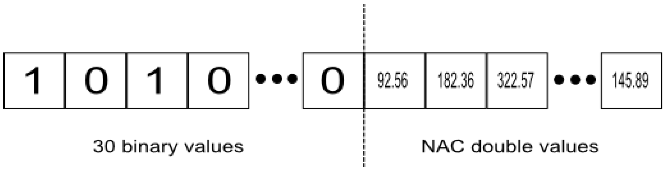
3.3.1. Chromosome Encoding

A decision directly related to the success of a GA in a specific application is the chromosome encoding, which is the encoded form of each individual belonging to the population. Chromosomes are combined in order to breed new individuals or mutated so as to incorporate direct changes. In any kind of problem examined in this work, the beam is divided in 30 equally spaced positions where the actuators can be positioned.
In the first kind of the problem (the Voltage Problem) every six consecutive positions become a group and the same voltage applies to all actuators of the same group. So, the chromosome encoding is just a sequence of decimal numbers equal to the number of groups. Each value of the chromosome is associated with the voltage that will be applied to all actuators of the group in the same place. Given that four different settings are tested with two, three, four, or five groups of actuators active respectively the chromosome length becomes two, three, four, or five.
Figure 1. Chromosome encoding for the location and voltage problem.
Actuators 02 00111 g002
In the second case of the problem (the Location and Voltage Problem) the chromosome consists of two parts (Figure 1). The left one is a sequence of 30 binary values carrying the information of presence (1) or absence (0) of an actuator at the predefined positions. The right part is the voltages that will be applied to each actuator that is present. The sum of ones in the left part should equal to the number of decimal values in the right part. As, for each run of the program, the number of actuators that will be active is known in advance, the chromosomes have a constant−length per run. In this version of the problem more degrees of freedom are given since different voltages can be applied to actuators that in the Voltage Problem belong to the same group. So, better results are expected and indeed the GA manages to find them as is shown in Section 4.

3.3.2. GA Implementation Issues

There are numerous GA implementations available in the form of callable libraries, frameworks or integrated environments. In this paper, MatLab’s Global Optimization Toolbox R2012a, which includes the Genetic Algorithm Toolbox was used. MatLab’s Global Optimization Toolbox starting from version R2011b has the capability of defining integer constraints out of the box. This was very convenient in our case given that the Location and Voltage Problem is a Mixed Integer optimization problem.

4. Numerical Results

This section presents numerical results from several representative problems. First, a benchmark problem is considered in order to validate the present optimization algorithm. Next, several illustrative optimization problems are investigated using the developed algorithm. All application examples focus on beams with surface bonded piezoelectric patches as actuators. The host beam is made of T300/976 graphite/epoxy and the piezoelectric layers are PZT G1195N. The length of the beam is equal to 300 mm, the depth is equal to 9.6 mm and width is equal to 40 mm. The thickness of the actuators is equal to 0.2 mm. The elastic constants of T300/976 graphite/epoxy are: E1 = 150 GPa, v12 = 0.3, G13 = 7.1 GPa. The piezoelectric material has the following properties: E1 = 63 GPa, v12=0.3, G13 = 24.2 GPa, e31 = 17.584 C/m2 and other entries in the piezoelectric stress matrix are zero. For comparison reason, in all the following examples the fitness value is scaled as [9]:
Actuators 02 00111 i016
It is noted that the greater the value of f, the greater the shape controllability is.
Figure 2. The smart beam structure.
Actuators 02 00111 g003

4.1. The Voltage Problem

The problem studied by Hadjigeorgiou et al. [9] is considered here in order to validate the optimization code presented in Section 3. The beam is divided evenly into 30 finite elements and five groups along the x direction as shown in Figure 2. Each group consists of six elements; on the upper surface of the elements actuators may be attached. The beam is clamped at the left hand side and is subjected to a concentrated load equal to 4 N at the free right end. The upper limit of the voltage is set to be 500 V. The pre−defined displacement field (desired shape) is given by Xd (x) = 0 and the aim is to calculate the actuator voltages required to induce this desired shape. The Voltage Problem is studied in two cases. In the first case, it is assumed that all the elements have a piezoelectric material layer bonded on its upper surface and the specified group is activated by the user. This is the same situation of [9]. In the second case, each element is considered as having no patch or being fully covered with piezoelectric material. A special assembly procedure was used to account for the piezoelectric actuator patches instead of complete layers of piezoelectric material throughout the structures. It is noted that in the former case, the stiffness characteristics of the beam remain constant throughout the shape control procedure, while, in the latter, they change depending on the number of actuators used. More precisely, the actuator patches contribute less to the beam stiffness than the continuous actuator layers in the first case. In addition, it is pointed out that for five actuator groups, the two cases of the problem (case 1 and case 2) are identical to that of [9].
The optimization problem for both problem cases is solved using the present developed genetic algorithm. The genetic algorithms were run for 100 generations and 40 individuals. Of several test cases run, the one exhibiting the best fitness is presented. The optimal values of voltages for the most efficient combinations of actuator groups to shape control of the beam are shown in Table 1. In the first row of Table 1 the values of optimal voltage predicted by Hadjigeorgiou et al. [9] are included. It can be noted that the values of fitness obtained by the developed algorithm are equal (case 1) or smaller (case 2) than those of [9] except for the last case of five groups of actuators, where the fitness value is bigger. Taking into account that the fitness values are calculated by Equation (19), we may conclude that: (i) the present algorithm is able to produce better results for the case of problems involving five actuator groups, (ii) the smaller values of fitness obtained in the second case are due to the smaller stiffness characteristics of the beam, leading to bigger displacement for the same load condition. In addition, this example highlights the inverse nature of the shape control, where uniqueness of solution is not guaranteed in general. This effect is also attributed to the inherited randomness of the GA. Most interestingly, all three models predict quite different voltage configurations but yet they all manage to match the desired shape quite well.

4.2. The Location and Voltage Problem

A beam with similar material and geometric properties as described in Section 4.1, is considered to calculate the optimal location and applied voltage of actuators in order to modify its shape. The simulation comprises structures with different boundary conditions: a clamped−free beam and a clamped−clamped beam. All the thirty elements are candidates for actuator locations. In addition, the piezoelectric patches are symmetrically located on the upper as well as on the lower side of the beam. Five GA runs were performed, each with different initial values of the design variables, and the best results obtained are presented in the following paragraphs.
In order to assess the behavior of the algorithmic approach, several runs were performed. For example, for the case of the Clamped Free problem, where the number of actuators is 18, 55 runs were performed using initial values generated with different random seed for each run. Results showed that for this particular case the maximum value of fitness function was f2 was 31.45, the minimum value was 27.35, the average value was 29.35, the standard deviation was 0.97, and the range of values was 4.1. Similar results were obtained for other instances of the problem demonstrating that the approach is fairly robust giving consistently good results.
Inclusion of the Great Deluge phase before the Genetic Algorithm added value to the approach. This is demonstrated by the following experiment scenario: For the case of the Clamped Free problem, 100 runs were performed using the Genetic Algorithm including the injection of solutions generated by the Great Deluge and another 100 runs were performed by deactivating the Great Deluge phase and letting the Genetic Algorithm form the initial population randomly. All runs where executed on a Windows7/64 bit machine equipped with Intel i7 860 processor and 16 GB of RAM. Each run took about eight minutes to complete. Results showed that the best 24 generated fitness values during the experiment were all achieved using the configuration of the solver that included the Great Deluge stage. Thus, a small number of good solutions (10% or less of the population size) injected to the initial population seem to drive the Genetic Algorithm to better solutions.
Table 1. Optimal values of voltages (clamped−free beam) for Xd(x) = 0.
Number of used Actuator GroupsMethodVoltage of the Actuator Groups (V)Fitness f2
12345
(1,3)[9] 432.610.00389.200.000.0017.86
Present (case 1)432.60389.2117.86
Present (case 2)438.87400.5517.76
(1,2,3)[9]324.83217.58272.110.000.0018.99
Present (case 1)324.91217.41272.2018.99
Present (case 2)325.35216.01277.5918.89
(1,2,3,4)[9] 320.15243.17169.88122.440.0022.14
Present (case 1)320.20243.30169.51122.5722.14
Present (case 2)320.33243.39169.21123.7922.03
(1,2,3,4,5)[9] 320.54240.47178.0998.5741.9423.41
Present (case 1)321.06241.18173.58107.4530.3723.61
Present (case 2)320.18243.09171.98107.9131.2023.56

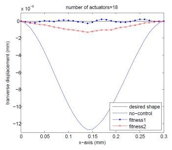
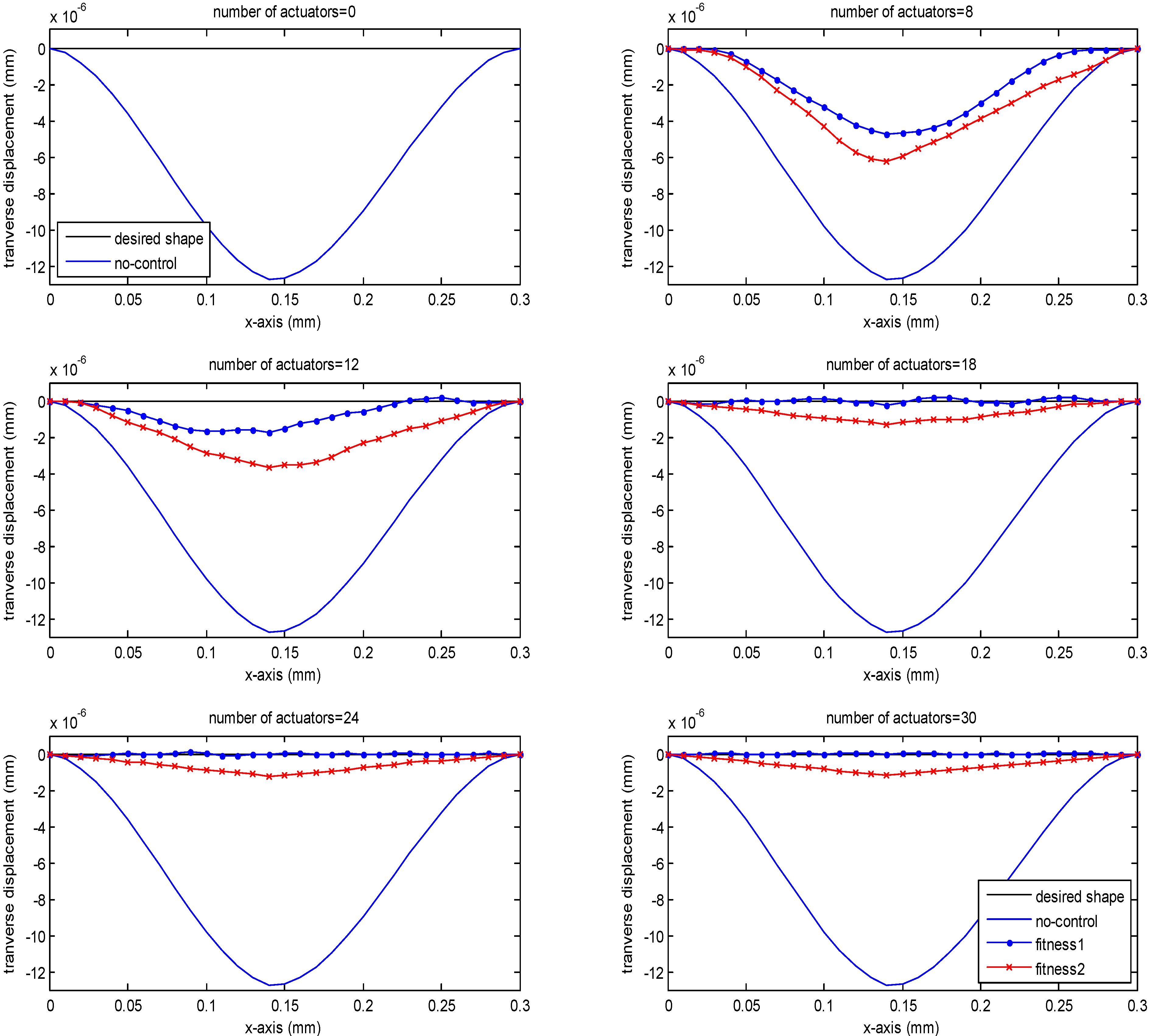
4.2.1. Clamped−Free Beam

First the case of a beam, which is clamped at the left−hand side and is subjected to a concentrated load equal to 4 N at the free right end, is considered. In this case, the lower limit of the voltage is set to be 0 V and the upper limit is set to be 240 V (limit imposed due to depoling of actuators). The desired shape is given by Xd(x) = 0. Table 2 shows the optimal solutions for placement of the actuators and the corresponding optimal voltages for various numbers of actuators. The genetic algorithms were run using the following parameters: Generations = 2,000, Population = 100, EliteCount = 2. Marginally better results can be obtained in some cases by further fine−tuning of GA parameters like EliteCount and mutation rate. It should be noted that for a small number of actuators (8, 12), the GA was terminated before 2000 generations. We observe that for a small number of actuators (8, 12) the optimal actuation voltages are close to the upper saturation limit and the optimal positions are closed to the clamped end. A graphical presentation of these results is given in Figure 3.
Table 2. Optimal Location and voltages of actuators within the 30 finite element mesh for Clamped−Free Beam.
Number of Actuators in Use
812182430
Number of Elementsf1f2f1f2f1f2f1f2f1f2
1240.00240.0072.88170.6295211.79178.82150.63172.21196.49171.86
20240.00205.33166.2474137.64240.00181.99164.26135.51165.25
3240.00240.0057.59239.5262224.250233.47160.70200.80159.43
4240.000227.7600237.75142.78152.82106.08154.16
5240.000240.00235.2183236.74150.8462.97148.71172.72147.67
6240.00240.00240.00240.00157.88141.92153.98141.55134.09142.17
7240.00240.00240.000144.00136.04133.83137.12175.95136.62
8240.0000240.00101.20131.17202.06129.9177.37130.25
9240.000240.000111.33124.1382.88125.06133.95125.01
100240.000240.00154.75179.14155.75118.98147.23118.82
110240.000240.00124.40020.06113.2189.92112.97
1200240.000138.96220.14142.41107.0688.79107.72
130240.00240.00000215.45101.73163.93101.21
14000240.00232.81149.81095.9054.6595.94
150000089.29089.5266.1089.88
1600240.000084.59223.2384.19137.7184.19
17000240.00180.02116.3754.8078.7216.6178.05
180000126.31050.7471.97126.1272.91
19000240.000167.23135.1199.1972.2466.33
200000118.1000017.6761.24
21000000087.0079.2754.98
2200240.0000132.40133.6372.4127.5949.26
230000194.29028.23060.2043.54
2400000124.3436.3677.4155.3537.67
250000000.12021.1931.62
2600000079.9968.893.4726.56
270000000031.4720.06
280000000027.6314.41
290000122.02017.0300.538.90
30000186.511.8746.152.0322.710.382.59
Fitness22.0016.1125.6019.0930.6520.8831.2923.1233.6626.77
As can be shown in Figure 3, in the last three cases a very good agreement was found between the desired shapes and the numerical results, showing that more actuators can control the deformation more efficiently. Compared to results in Figure 3, we can see that the maximum nodal displacement for the optimal solution obtained using fitness f1 is smaller than the one obtained using f2 (e.g., 7.536e−6m compared to 1.093e−5m for 8 actuators). Hence, it can be concluded that the deflection controlled by fitness f1 is closer to the desired shape than the one controlled by f2.
Figure 3. The centerline of the cantilever smart beam under the action of various numbers of actuators for Xd(x) = 0 with the optimal location of the actuators and the optimal values of actuation voltages.
Actuators 02 00111 g004

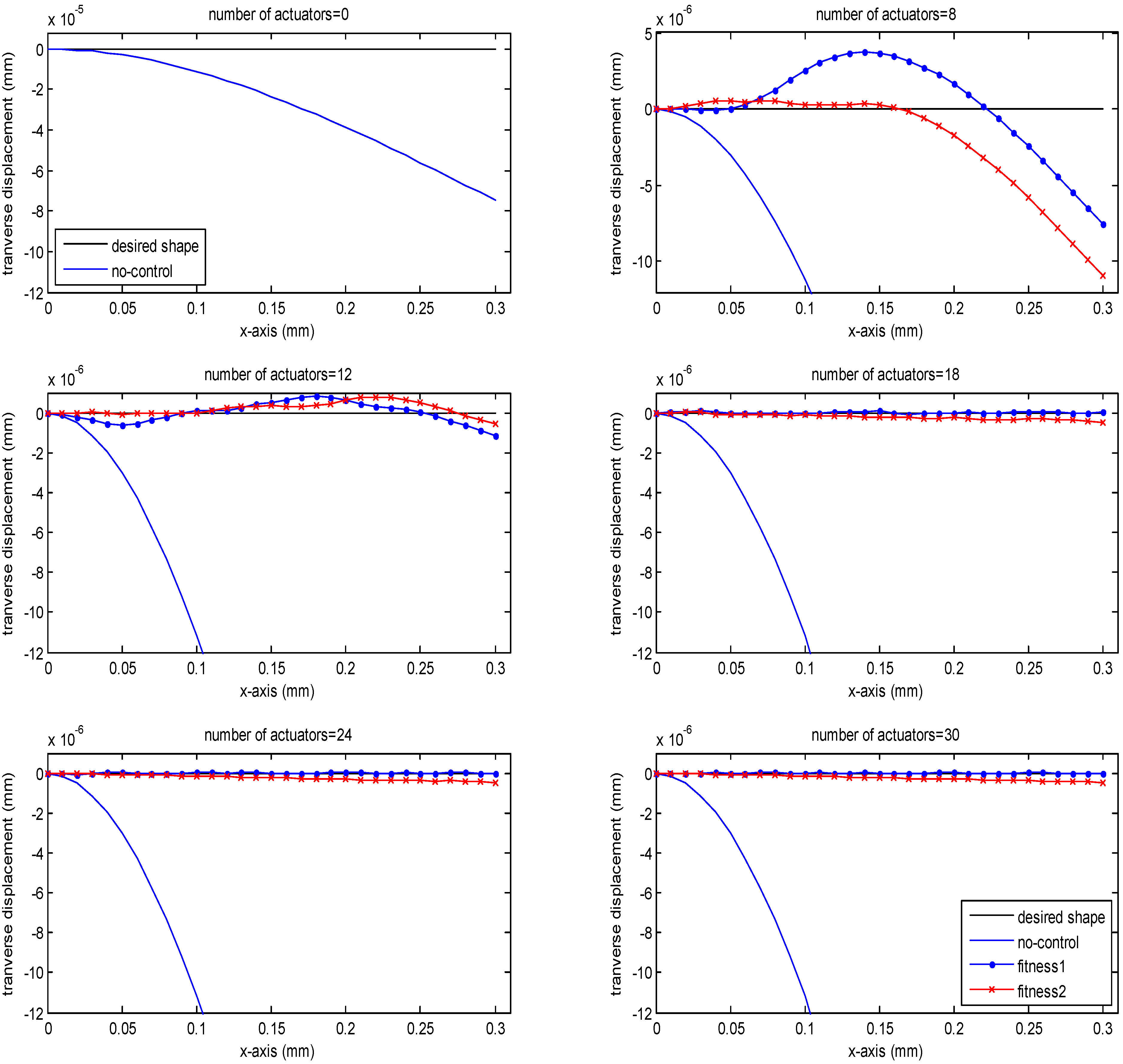
4.2.2. Clamped−Clamped Beam

Second, the case where the beam clamps on both sides and is subjected to a concentrated load equal to 40 N at the center is considered. The lower limit of the voltage is set to be −240 V and the upper limit is set to be 240 V. The pre−defined displacement field (desired shape) is given by Xd(x) = 0. The optimal values of voltages for the most efficient combinations of number of actuators to shape control of the beam are presented in Table 3. The GA runs using the following parameters: Generations = 3,000, Population = 150, EliteCount = 0. It should be noted that, for a small number of actuators (8, 12), the GA was terminated before 1,500 generations. We observe that for a small number of actuators (8, 12) the optimal positions of the actuators are close to the clamped ends where the optimal actuation voltages are close to the upper saturation limit and at the middle of the beam where the optimal actuation voltages are close to the lower saturation limit. A graphical presentation of these results is given in Figure 4. By comparing the curves in Figure 4, it can be seen that the deflection controlled by fitness f1 is closer to the desired shape than the one controlled by f2 (the maximum displacement from 3.67e−6m is reduced to 1.72e−6m for 12 actuators). Again, the results indicate that increasing the number of actuators has a beneficial effect on controlling the shape of the beam.

5. Conclusions

A mathematical model of a laminated composite beam with bonded piezoelectric patches used as actuators is considered in this study. The model is built using finite element method and is applied as a platform for the investigation of shape control of the beam. Shape control was applied to a beam structure with different boundary conditions. The optimal values for the locations of the piezo−actuators and optimal voltages for shape control are determined for clamped−free and clamped−clamped beams by using a genetic optimization procedure. A two−step process including Great Deluge and then a Genetic Algorithm has been performed in order to improve search efficiency. The results presented above demonstrate the capability of the proposed hybrid GA approach in determining optimal voltages and locations of control actuators within a large number of possible positions.
Numerical results on a benchmark problem validate both the finite element code being used as well as the optimization algorithm. Examples that demonstrate the capabilities and efficiency of the developed optimization algorithm in both clamped−free and clamped−clamped beam problems were presented.
In the near future, our research team plans to apply the proposed hybrid GA to more realistic engineering problems such as plate structures.
Table 3. Optimal Location and voltages of actuators within the 30 finite element mesh for Clamped−Clamped Beam.
Number of ElementsNumber of Actuators in Use
812182430
f1f2f1f2f1f2f1f2f1f2
1240.00240.00239.98240.00240.00240.00240.00235.43239.95211.92
2240.00240.0000240.00240.00240.00205.09196.47180.26
300239.970240.00213.31240.00174.19141.02149.30
40000240.00157.7599.60143.3133.89118.34
5000240.000169.2170.087112.4372.0387.38
60000003.87108.2372.3256.42
70000157.3591.2393.210−51.2925.46
8000−168.7765.58046.6446.4748.25−5.51
90000−172.580−59.20−11.14−162.20−36.47
100−240.000000−240.00−42.001.25−67.42
11−240.00000−240.00131.610−72.92−151.25−98.38
1200−239.96−240.000121.530−103.80−144.01−129.35
1300239.97−240.00−240.00156.44−240.00−134.69−230.12−160.31
14−240.000239.980−240.00191.35−240.00−165.58−239.98−191.27
1500239.99−240.000197.23−240.00−167.45−239.93−193.21
16−240.00−240.00239.98−240.00−240.00174.10−240.00−140.27−222.46−166.13
170−240.0000−240.00150.97−191.31−158.49−186.16−139.05
180000−192.47230.1400−106.64−111.97
1900239.930−199.990−143.09−125.64−115.69−84.89
200−240.000−240.0000−96.150−54.88−57.80
2100000−184.0513.020−67.16−30.72
22000000−46.170−66.87−3.64
230000129.42014.1197.5561.6323.44
24000000005.1550.52
25000240.00098.34139.55144.6945.8877.61
260000000131.2595.75104.68
270240.00239.93240.0000240.00158.41100.36131.77
28240.00240.00239.97240.00240.00240.000185.55102.98158.85
29240.000239.960240.000240.00214.49206.31185.93
30240.000239.98240.00185.24211.60240.00240.00239.91213.64
Fitness22.2416.9224.3118.1728.4620.7930.2622.3731.9024.97
Figure 4. The centerline of the clamped−clamped smart beam under the action of various numbers of actuators for Xd(x) = 0 with the optimal values of actuation voltages.
Actuators 02 00111 g005

Acknowledgements

This research has been co−financed by the European Union (European Social Fund–ESF) and Greek national funds through the Operational Program “Education and Lifelong Learning” of the National Strategic Reference Framework (NSRF)−Research Funding Program: ARCHIMEDES III−Investing in knowledge society through the European Social Fund. The authors gratefully acknowledge this support.

References

  1. Chopra, I. Review of state of art of smart materials structures and integrated systems. AIAA J. 2002, 40, 2145–2187. [Google Scholar] [CrossRef]
  2. Srinivasan, A.V.; McFarland, D.M. Smart Structures: Analysis and Design; Cambridge University Press: Cambridge, UK, 2001. [Google Scholar]
  3. Irschik, H. A review on static and dynamic shape control of structures by piezoelectric actuation. Eng. Struct. 2002, 24, 5–11. [Google Scholar] [CrossRef]
  4. Tong, D.; Williams, R.L.; Agrawal, S.K. Optimal shape control of composite thin plates with piezoelectric actuators. J. Intell. Mater. Syst. Struct. 1998, 9, 458–467. [Google Scholar] [CrossRef]
  5. Agrawal, B.N.; Treanor, K.E. Shape control of a beam using piezoelectric actuators. Smart Mater. Struct. 1999, 8, 729–740. [Google Scholar] [CrossRef]
  6. Chee, C.; Tong, L.; Steven, G.P. Piezoelectric actuator orientation optimization for static shape control of composite plates. Compos. Struct. 2002, 55, 169–184. [Google Scholar] [CrossRef]
  7. Onoda, J.; Hanawa, Y. Actuator placement optimization by genetic and improved simulated annealing algorithms. AIAA J. 1993, 31, 1167–1169. [Google Scholar] [CrossRef]
  8. Mota Silva, S.; Ribeiro, R.R.; Rodrigues, J.D.; Vaz, M.A.P.; Monteiro, J.M. The application of genetic algorithms for shape control with piezoelectric patches—An experimental comparison. Smart Mater. Struct. 2004, 13, 220–226. [Google Scholar]
  9. Hadjigeorgiou, E.P.; Stavroulakis, G.E.; Massalas, C.V. Shape control and damage identification of beams using piezoelectric actuation and genetic optimization. Int. J. Eng. Sci. 2006, 44, 409–421. [Google Scholar] [CrossRef]
  10. Frecker, M.I. Recent advances in optimization of smart structures and actuators. Int. J. Eng. Sci. 2003, 14, 207–216. [Google Scholar]
  11. Preumont, A. Vibration Control of Active Structures: An introduction; Springer-Verlag: Berlin Heidelberg, Germany, 2011. [Google Scholar]
  12. Thomas, O.; Deü, J.F.; Ducarne, J. Vibrations of an elastic structure with shunted piezoelectric patches: Efficient finite element formulation and electromechanical coupling coefficients. Int. J. Numer. Meth. Eng. 2009, 80.2, 235–268. [Google Scholar] [CrossRef]
  13. Goldberg, D. Genetic Algorithms in Search, Optimization, and Machine Learning; Addison−Wesley Professional: New York, NY, USA, 1989. [Google Scholar]
  14. Back, T.; Fogel, D.B.; Michalewicz, Z. Handbook of Evolutionary Computationl, 1st ed.; IOP Publishing Ltd.: Bristol, UK, 1997. [Google Scholar]
  15. Reddy, N.J. Mechanics of Laminated Composite Plates: Theory and Analysis; CRC: New York, NY, USA, 1997. [Google Scholar]
  16. Man, K.F.; Tang, K.S.; Kwong, S. Genetic algorithms: Concepts and applications. IEEE Trans. Ind. Electr. 1996, 43, 519–534. [Google Scholar]
  17. Dueck, G. New Optimization Heuristics the great deluge algorithm and the record−to−record travel. J. Comput. Phys. 1993, 104, 86–92. [Google Scholar] [CrossRef]
  18. McMullan, P. An extended implementation of the great deluge algorithm for course timetabling. Lect. Note. Comput. Sci. 2007, 4887, 538–545. [Google Scholar]
  19. Ozcan, E.; Misir, M.; Ochoa, G.; Burke, E.K. A Reinforcement learning−great−deluge hyper−heuristic for examination timetabling. Int. J. Appl. Metah. Comput. 2010, 1, 39–59. [Google Scholar]
  20. Kendall, G.; Mohamad, M. Channel Assignment in Cellular Communication Using a Great Deluge Hyper−Heuristic. In Proceedings of 12th IEEE International Conference on Networks, Berlin, Germany, 16–19 November 2004; pp. 769–773.
  21. Nahas, N.; Khatab, A.; Ait−Kadi, D.; Nourelfath, M. Extended great deluge algorithm for the imperfect preventive maintenance optimization of multi−state systems. Reliab. Eng. Syst. Safety 2008, 99, 1658–1672. [Google Scholar]
  22. Baykasoglu, A. Design optimization with chaos embedded great deluge algorithm. Appl. Soft Comput. 2012, 12, 1055–1067. [Google Scholar] [CrossRef]

Appendix

Detailed expressions of the mass and stiffness matrices as well as loading vectors that appear in the paper.
Actuators 02 00111 i017
Actuators 02 00111 i018
Actuators 02 00111 i019
Actuators 02 00111 i020
Actuators 02 00111 i021
Actuators 02 00111 i022
Actuators 02 00111 i023

