Article

Double-Acting Sleeve Muscle Actuator for Bio-Robotic Systems

Department of Mechanical Engineering, University of Alabama, 290 Hardaway Hall, Box 870276, Tuscaloosa, AL 35487-0276, USA
*
Author to whom correspondence should be addressed.
Actuators 2013, 2(4), 129-144; https://doi.org/10.3390/act2040129
Submission received: 5 November 2013 / Revised: 14 November 2013 / Accepted: 20 November 2013 / Published: 25 November 2013
(This article belongs to the Special Issue Human Centered Actuators)

Abstract

:
This paper presents a new type of muscle-like actuator, namely double-acting (DA) sleeve muscle actuator, which is suitable for the actuation of biologically-inspired and biomedical robotic systems, especially those serving human-assistance purposes (prostheses, orthoses, etc.). Developed based on the traditional pneumatic muscle actuator, the new DA sleeve muscle incorporates a unique insert at the center. With the insert occupying the central portion of the internal volume, this new actuator enjoys multiple advantages relative to the traditional pneumatic muscle, including a consistent increase of force capacity over the entire range of motion, and a significant decrease of energy consumption in operation. Furthermore, the insert encompasses an additional chamber, which generates an extension force when pressurized. As such, this new actuator provides a unique bi-directional actuation capability, and, thus, has a potential to significantly simplify the design of a muscle actuator-powered robotic system. To demonstrate this new actuator concept, a prototype has been designed and fabricated, and experiments conducted on this prototype demonstrated the enhanced force capacity and the unique bi-directional actuation capability.

Graphical Abstract

1. Introduction

Taking inspiration from biological organisms has been one of the major methods of innovation in modern robotics research. By mimicking the structure and functioning mechanism of humans or animals, a biologically-inspired robotic system leverages the underlying biological principles, and, thus, enjoys similar advantages of its biological counterparts. Artificial muscle actuator is a typical example. For the actuation of biologically-inspired robotic systems, investigators have expended significant efforts in developing the robotic counterpart of biological muscles. As a result, various types of artificial muscle actuators have been developed, for example, pneumatic muscle actuators [1], piezoelectric actuators [2], shape memory alloy actuators [3], and dielectric elastomer actuators [4]. Among these various choices, pneumatic muscle has drawn heavy attention from researchers as a highly competitive choice for bio-robotic systems, especially those serving human-assistance purposes (prostheses, orthoses, etc.). Also known as McKibben muscle or fluidic muscle, the pneumatic muscle simulates the functioning mechanism of biological skeletal muscles through the pressurizing of an air-tight tube surrounded by an inextensible mesh (Figure 1). With the interior volume pressurized, the tube expands in the radial direction and shortens in the axial direction, generating a contraction force to the external load. With this structure, the pneumatic muscle possesses multiple unique advantages, including simple structure, high power density, and similar elastic characteristics to biological skeletal muscles. Researchers have reported the power density values ranging from 1 kW/kg [5] to 10 kW/kg [6], significantly higher than the typical value for electric motors (~0.1 kW/kg as reported by Isermann and Raab [7]). The advantage in power density enables a large power output within a compact package, and, thus, makes the pneumatic muscle a highly competitive actuation approach for the robotic systems with strict weight and volumetric constraints. Moreover, the actuation force decreases with the contraction, which can be utilized to simulate the elastic behavior of biological skeletal muscles [8]. With these unique characteristics, pneumatic muscle has seen extensive use in robotic systems. For example, pneumatic muscle has been used to drive lower-limb prosthetic devices [9,10] and rehabilitation exoskeleton systems [11,12]. Please see the review paper by Zhang and Philen [13] for more robotic applications of pneumatic muscle actuators.
Figure 1. Structure (a) and actuation mechanism (b) of the pneumatic muscle.
Actuators 02 00129 g001
Despite the extensive robotic application, the innovation on the pneumatic muscle itself has been limited, with the flexible membrane as the major focus of investigation. For example, the bi-layer membrane structure as shown in Figure 1a can be modified into an embedded design, in which the load-bearing fibers are embedded into the flexible air-tight membrane to form a single-layer structure [14], which has been adopted in a large number of pneumatic muscle designs, including the commercial products from FESTO. A more recent innovation is the pleated muscle concept by Daerden and Lefeber [15], in which the inflatable membrane is replaced with a flexible but non-extendible membrane folded along the longitude direction. In spite of these modifications, the structure and functioning mechanism of pneumatic muscle have largely remained unchanged since its inception.
In the robotic application of pneumatic muscle, a major challenge is its single-acting nature and the resultant complexity in the actuation mechanism. Pneumatic muscle only generates a contraction force. As such, bi-directional actuation of a robotic joint usually requires two actuators in an antagonistic configuration (Figure 2), making the system bulky and complex. The double-acting (DA) sleeve muscle described in this paper addresses this issue with a fundamental change to the structure of pneumatic muscle. In this new structure, an extra chamber is introduced at the center of the original pneumatic muscle, which is able to generate an extension force to complement the contraction force generated by the membrane. With this bi-directional actuation capability, the DA sleeve muscle has a potential to significantly simplify the design shown in Figure 2 by eliminating the need for a second muscle actuator. Note that this work is built upon the original sleeve muscle concept, which has been demonstrated to provide multiple advantages over traditional pneumatic muscle, such as consistent increase of force capacity over the entire range of motion, and a significant decrease of energy consumption in operation [16]. Sharing these outstanding properties, the DA sleeve muscle actuator represents a significant step forward over the traditional pneumatic muscle and can potentially become a highly competitive actuator choice for the future high-performance robotic systems.
Figure 2. Typical configuration of a pneumatic muscle-actuated robotic system.
Actuators 02 00129 g002
The paper is organized as follows: Section 2 presents the rationale and basic structure of the DA sleeve muscle design; Section 3 presents the design of a DA sleeve muscle prototype and the corresponding experimental results; Section 4 discusses the future work on the design of an integrated DA sleeve muscle and the application of DA sleeve muscle in bio-robotic systems; Section 5 presents the conclusions of this paper.

2. Rationale and Basic Structure of the DA Sleeve Muscle

In the section, the working principle of pneumatic muscle is analyzed to form the theoretic basis and inspiration for incorporating the cylindrical insert to eliminate the central volume of pneumatic muscle. As a result, the initial sleeve muscle concept is established, which provides an enhanced force capacity and reduced energy consumption compared with the traditional pneumatic muscle. Subsequently, the concept of DA sleeve muscle is introduced, which provides a unique bi-directional actuation capability by isolating the central volume into an additional chamber and leveraging the resultant extension force.

2.1. Sleeve Muscle: Inspired by the Force Analysis of Pneumatic Muscle

As a muscle-like actuator, the pneumatic muscle simulates the function of biological skeletal muscle by generating a contraction force to the external load. Specifically, the flexible membrane of the muscle actuator contracts under the internal gas pressure. In this process, the membrane also expands radially, enlarging the internal volume of the actuator. Understanding the volume change is critical in the study of the pneumatic muscle’s functioning mechanism, as demonstrated by the following derivation of its pressure-force relationship.
Neglecting the strain energy in the membrane, the following equation can be obtained by applying the principle of virtual work:
dWout = dWin
where Wout and Win are the input work and output work, respectively. dWout can be expressed as:
dWout = −FdL
where F is the actuator contraction force, and L the length of the pneumatic muscle. dWin can be expressed as:
dWin = (P − Patm)dV
where P is the actuator internal pressure, Patm is the atmosphere pressure, and V is the actuator internal volume. Combining the three equations above, the force output can be expressed as:
F = (− dV/dL)·(P − Patm)
As indicated by this equation, the contraction force F is proportional to the gauge pressure (P − Patm), with the coefficient of proportionality as (− dV/dL). Therefore, in order to generate a contraction force output, the internal volume V needs to expand when the muscle length L shortens, resulting in a positive value of (− dV/dL). This is always true for a regular pneumatic muscle in its normal operation, until the maximum contraction is reached.
Figure 3. 
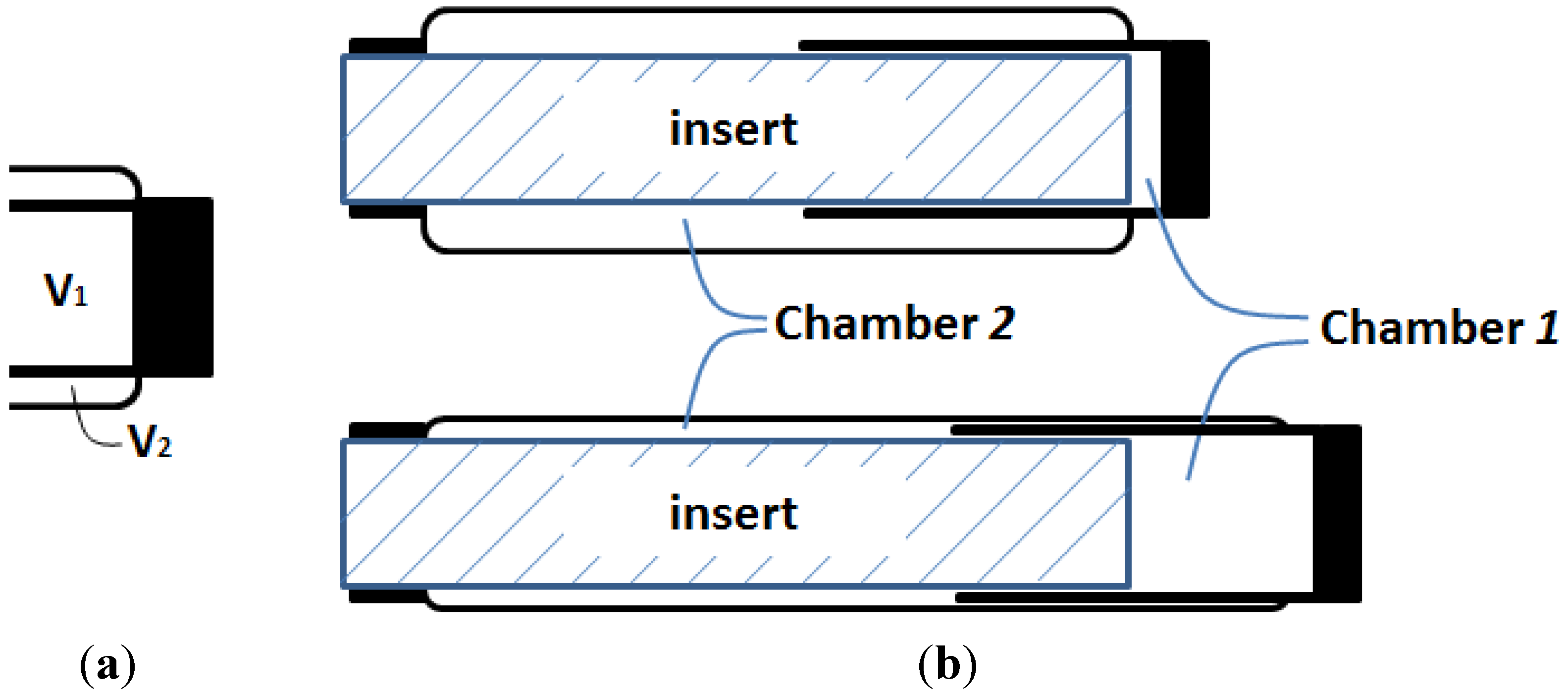
Dividing the internal volume into two parts: V1 and V2. Note that V2 is negligible at the equilibrium state.
Actuators 02 00129 g003
In the analysis above, the volume inside the pneumatic muscle is treated as a whole. However, one can gain further insight of the force-generating process by hypothetically dividing the internal volume into two portions, including V1, a cylindrical volume at the center of the muscle, whose diameter is equal to that of the muscle’ end connectors; and V2, a ring-shaped volume surrounding V1 (Figure 3).
At the equilibrium state, the pneumatic muscle’s internal volume is close to a cylinder, and thus V2 is negligible at this state. Both V1 and V2 change with the length of the actuator, and, thus, the total contraction force can be expressed as the sum of F1 and F2:
F = F1 + F2
where F1 and F2 are the contributions of the changes of V1 and V2, respectively:
Actuators 02 00129 i001
Actuators 02 00129 i002
To analyze the contributions of these volume changes, V1 can be expressed as the product of the fixed cross-sectional area Actuators 02 00129 i009 (D is the diameter of the muscle end connector) and the muscle length L, and, thus, decreases with the shortening of the muscle. Consequently, the contribution of V1 to the contraction force is always negative, as indicated by the following equation:
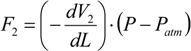
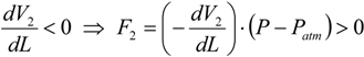
Actuators 02 00129 i003
On the other hand, V2 expands as the pneumatic muscle contracts, and thus contributes positively to the generation of the output force:
Actuators 02 00129 i004
Based on these two equations, it can be inferred that the total contraction force F is always less than F2, due to the fact that the negative 
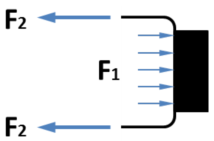
F1 reduces the total force output. This conclusion can be better explained with a simple force analysis as shown in Figure 4. Among the two forces applied to the moving end of the pneumatic muscle, F2 is the contraction force generated by the membrane, while F1 is the extension force applied to the end connector due to the internal air pressure. When these forces are applied simultaneously, F1 partially cancels out F2, resulting in a loss of the actuator force capacity.
Figure 4. Contributions of V1 and V2 to the contraction force: F1 is extension force applied to the end connector due to the internal pressure, and F2 is extension force by the membrane.
Actuators 02 00129 g004
This observation inspired the concept of the initial sleeve muscle concept, in which a rigid cylindrical bar or tube is inserted into the center of the muscle actuator (Figure 5).
Figure 5. Schematic of the initial sleeve muscle actuator.
Actuators 02 00129 g005
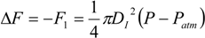
Note that the cylindrical insert incorporates a built-in air pathway to enable the access to the volume between the insert and the membrane. As such, the membrane is still able to generate the desired contraction force to the moving end, which now slides on the smooth outer surface of the insert. More importantly, with the central space occupied by the insert, the volume V1 is largely eliminated, which in turn eliminates the corresponding extension force F1. Correspondingly, an increase in the actuator force capacity can be obtained:
Actuators 02 00129 i005
where DI is the outer diameter of the insert, which needs to be slightly less than the muscle end-connector diameter D to ensure the structural strength of the moving end. From Equation (10), it can be deduced that, under a certain internal pressure, the magnitude of force increase is a constant, i.e., not affected by the contraction of the muscle. As such, this effect is especially important in the large-contraction region, where the contraction force is much less than that at the equilibrium state.
In addition to the greater force capacity, the sleeve muscle also features a substantial reduction in energy consumption compared with the traditional pneumatic muscle. This can be primarily attributed to two factors: (1) The internal volume has been significantly reduced after incorporating the insert; and (2) With the greater force capacity, the sleeve muscle requires a lower internal air pressure to generate the desired force output, also contributing to the energy saving. Experiments conducted on a sleeve muscle prototype demonstrated that, depending on the percentage of muscle contraction, the energy consumption can be lowered by 20%~37% compared with an identical pneumatic muscle without the insert [16].

2.2. DA Sleeve Muscle: Making Full Use of the Potential Provided by Sleeve Muscle

In the theoretical analysis supporting the inception of the sleeve muscle, a key observation is the totally opposite contributions from the volumes V1 and V2. Pressurizing V1 generates an extension force, while pressurizing V2 generates a contraction force. In the traditional pneumatic muscle, V1 and V2 are inseparable, causing the extension force to partially offset the contraction force and resulting in a total force output lower than the contraction force. In the initial sleeve muscle as described above, V1 (along with the corresponding extension force) is largely eliminated with the insert, generating a greater force output under the same internal pressure.
Despite the successful performance enhancement with the initial sleeve muscle, eliminating V1 only makes partial use of the potential provided by the approach of incorporating an insert into the muscle actuator. Since the contributions from V1 and V2 are totally opposite, what if we separate them and let them contribute separately and independently to the actuation effort, as in Figure 6a? If this hypothetical structural change can be realized, the resultant muscle actuator can not only generate a greater contraction force, but also generate an extension force for bi-directional actuation.
Figure 6. Oncept of the DA sleeve muscle: (a) Separating V1 and V2 with a rigid shell, and (b) the resulting DA sleeve muscle structure.
Actuators 02 00129 g006
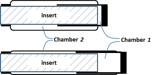
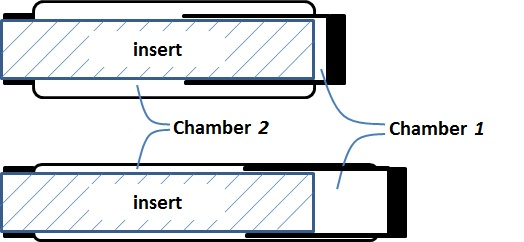
The research inspired by the hypothetical question above leads to a new double-acting sleeve muscle actuator, as shown in Figure 6b. Instead of simply eliminating V1, this new actuator introduces an additional pressurizable chamber (Chamber 1) over the moving end of the sleeve muscle. This additional chamber essentially isolates the portion of the original V1 that is unaffected by the motion of the moving end, and thus retains the extension force associated with the volume V1. With this unique structure, the DA sleeve muscle features two separate chambers that can be individually pressurized or exhausted for contraction and extension, providing a truly bi-directional robotic actuator. Note that the structure in Figure 6b is similar to a U.S. patent filed by Sato [17], in which a telescoping structure is incorporated at the center of the traditional pneumatic muscle. However, there is a fundamental difference: The actuator in the Sato patent is a single-acting actuator, and its central structure is introduced to reduce the inner volume of the actuator. In comparison, the DA sleeve muscle is double-acting, with the central structure being able to generate an extension force to the external load. This bi-directional actuation capability is unique.
A few details in the schematic in Figure 6b are worth elaborating. First, the two separate chambers can be independently controlled with respect to their internal pressures, and thus a significant pressure differential may be applied to the rigid shell that separates the chambers. As such, a thin-wall shell with sufficient strength, such as those used in pneumatic cylinders, is required. The shell must be rigidly connected to the moving end of the muscle actuator with proper sealing to provide the required airtightness. In addition, the shell slides on the outer surface of the stationary insert during operation, which requires proper moving seal at the surface of contact. U-Cup is the seal of recommendation, since this type of seal does not rely on the initial compression to seal, and thus generates lower friction in sliding. Note that the pressure differential across the seal is undetermined, i.e., the Chamber 1 pressure can be higher or lower than the Chamber 2 pressure in operation. Therefore, two antagonistically placed U-Cups are needed to provide the desired sealing effect under any arbitrary pressure differential.
Based on the schematic in Figure 6b, the force output can be expressed as a function of the pressures in the chambers. For the membrane pulling force, various theoretical or empirical models have been established with different levels of complexity and accuracy. Please see the review paper by Zhang and Philen [13] for more details. To avoid losing generality in force calculation, assume the membrane force model takes the following form:
FPM = FPM(P,L)
in which P is the internal air pressure and L is the length of the actuator. For the DA sleeve muscle, the pressure applied to the membrane is the Chamber 2 pressure 
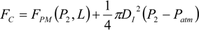
P2. Also, compared with the pneumatic muscle, the DA sleeve muscle provides an increase in the force output as expressed by Equation (10). As such, the contraction force of the DA sleeve muscle FC can be expressed as:
Actuators 02 00129 i006
For the extension force, the cross-sectional area is a constant Actuators 02 00129 i009
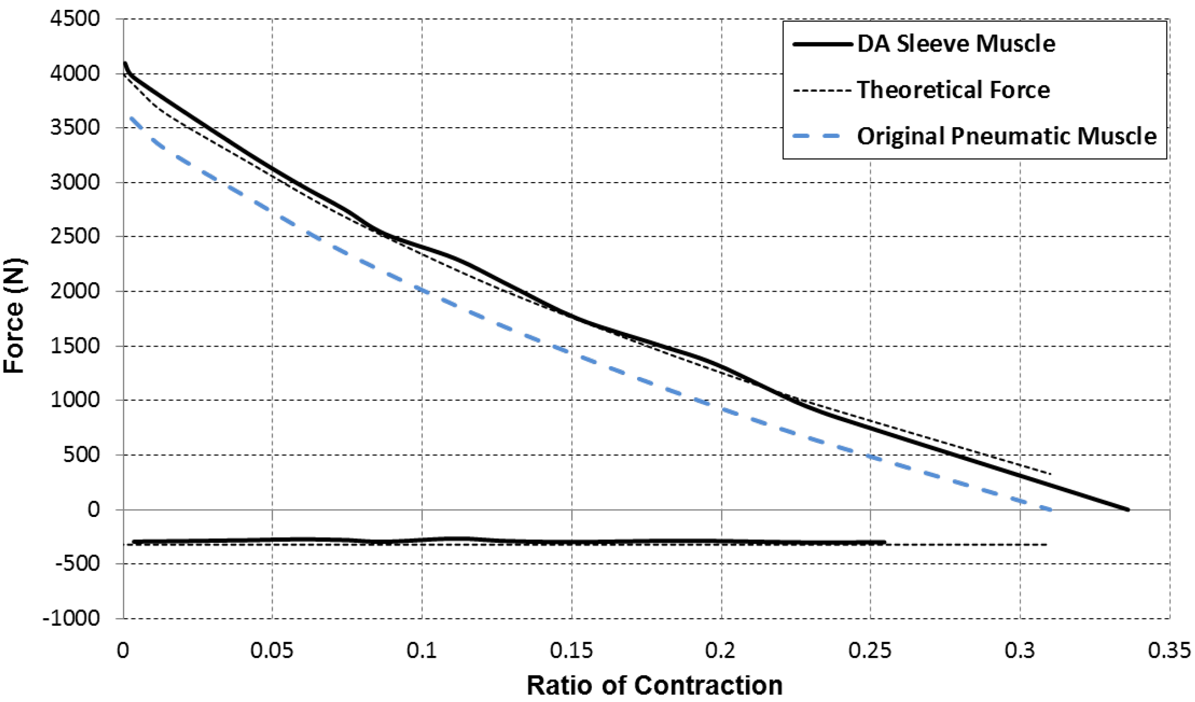
. As such, the extension force can be expressed as:
Actuators 02 00129 i007
in which P1 is the Chamber 1 pressure. Combining Equations (12) and (13), the force output of the DA sleeve muscle is:
Actuators 02 00129 i008
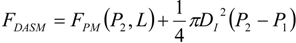
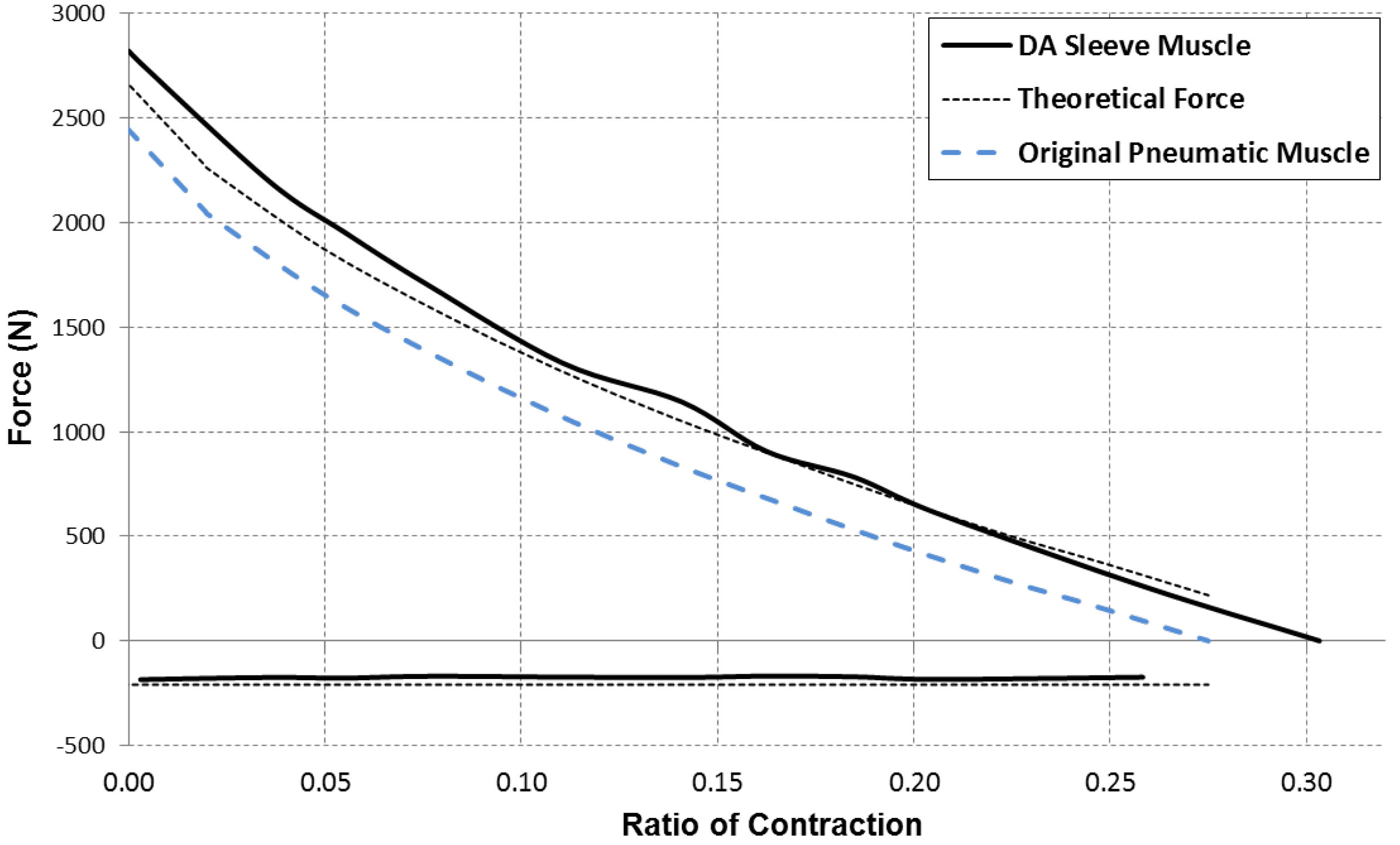
for which the contraction force is considered as positive. Based on this equation, a comparison of the force capacity of the DA sleeve muscle versus the traditional pneumatic muscle is shown in Figure 7. From this figure, one can clearly see the increased contraction force capacity (positive) and the newly added extension force capacity (negative) provided by the DA sleeve muscle, indicating the significant performance enhancement of this new muscle actuator. Note that the simple analysis in this section is intended to quantify the DA sleeve muscle’s performance enhancement in comparison with the corresponding pneumatic muscle (with the identical membrane). The performance enhancement results from the structural modification, whose effect on the actuation force is relatively easy to analyze (compared with the contraction force of the membrane). Therefore, the simple analysis above can provide a satisfactory result in determining the DA sleeve muscle’s actuation force, which has been experimentally demonstrated, as summarized in the subsequent section. To use the result (Equation (14)), any pneumatic muscle force model with acceptable accuracy can be used to determine FPM, and the actuation force of the corresponding DA sleeve muscle can be calculated accordingly.
Figure 7. The force capacity of the DA sleeve muscle in comparison with that of the traditional pneumatic muscle.
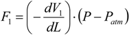
Actuators 02 00129 g007

3. DA Sleeve Muscle Prototype and Experimental Results

Based on the schematic of the DA sleeve muscle, a prototype has been fabricated and tested. To reduce the difficulty in fabricating this initial prototype, a commercial pneumatic muscle (DMSP-40-180N-RM-CM, FESTO, Esslingen, Germany) was selected as the basis for modification. Both ends of this commercial product were drilled through to accommodate the insert structure in the center, as shown in Figure 8a. In order to attach a rigid shell to the moving end, a commercial pneumatic cylinder (Model 124-R, Bimba Manufacturing, University Park, IL, USA) was selected and modified. Specifically, on the rodless end of this single-acting cylinder is a cylindrical aluminum connector. After cutting the stainless steel body shell to the desired length (Figure 8b), the aluminum connector was fitted into the through hole in the muscle actuator to form the moving end. Teflon tape and adhesive were used to obtain the required sealing effect. On the stationary end, a solid aluminum insert is mounted to the through hole, and it provides the required air pathways to access the two chambers (Figure 8c). In addition, two U-Cups, mounted in slots located close to the end of the insert, provide the sliding seal between the chambers during operation.
After the prototype was assembled (Figure 8d), experiments were conducted to characterize its force capacity under different internal pressures and contractions. The experimental apparatus is mounted horizontally on a vibration-isolated steel table, on which the fixed end is mounted on a stationary bracket. To alter the actuator length in the experiment, a winch was used to pull the free end of the actuator through a steel cable, with the actuator force measured through a load cell mounted between the actuator and the cable. Additionally, a linear potentiometer is attached to the moving end of the actuator to measure its displacement (and hence the contraction). To alter the internal pressure, a simple proportional control loop was constructed, in which a proportional valve (MPYE-5-M5-010-B, FESTO, Esslingen, Germany) modulates the gas flow into or out of the muscle actuator, and a pressure transducer (SDET-22T-D25-G14-U-M12, FESTO, Esslingen, Germany) provides the pressure feedback. The control loop was implemented on a desktop computer that runs MATLAB Simulink Real-Time Workshop, which also recorded the measured force output of the muscle actuator. The primary focus of the experiments was the verification of the force capacity of the DA sleeve muscle as expressed by Equation (14). To serve this purpose, the force output was measured when the chamber pressures and actuator length took a wide range of values, and the measured data were compared with the theoretical values as calculated with Equation (14). Two sets of typical data are shown in Figure 9 and Figure 10, with the corresponding block forces (at zero contraction) and free contractions (with zero force output) summarized in Table 1. In the figures, the force-length curves of the pneumatic muscle (dashed lines in blue) were experimentally determined. Based on these curves, the theoretical force curves for contraction and extension (dashed lines in black) are calculated according to Equation (14). As can be seen in these figures, the measured contraction force by DA sleeve muscle displays a consistent increase over the entire range of motion compared with that provided by the traditional pneumatic muscle. In addition, the DA sleeve muscle is able to provide an extension force that the traditional pneumatic muscle is not able to provide (the flat curves with negative values). As the extension force is provided by the telescoping insert with a constant cross-sectional area, the magnitude of the force is unaffected by the actuator length. Furthermore, the measured curves display a close match to the theoretic curves, demonstrating the validity of the pressure-force Equation (14).
Figure 8. Prototype of the DA sleeve muscle: (a) The modified commercial pneumatic muscle; (b) The aluminum connector with stainless steel shell; (c) The solid aluminum insert mounted on the stationary end; (d) The assembled actuator prototype.
Actuators 02 00129 g008
Figure 9. Measured and theoretically calculated force outputs of the DA sleeve muscle in comparison with the force output of the original unmodified pneumatic muscle under the gauge pressure of 276 kPa (40 PSI).
Actuators 02 00129 g009
Figure 10. Measured and theoretically calculated force outputs of the DA sleeve muscle in comparison with the force output of the original unmodified pneumatic muscle under the gauge pressure of 414 kPa (60 PSI).
Actuators 02 00129 g010
Table 1. Comparison of block forces and free contractions.
Pressure (PSI)Pressure (kPa)Block Force (N)Free Contraction (%)
Pneumatic40276244327.5
Muscle60414366631.0
DA Sleeve40276282030.3
Muscle60414409633.6
DA Sleeve402762661
Muscle Model604143994
% of Increase4027615.4%10.1%
DASM vs. PM6041411.7%8.4%
% of Model402765.6%
Error604142.5%
In addition to the force capacity, the energy density of the DA sleeve muscle has also been studied. The improved performance of the DA sleeve muscle is obtained by the introduction of the insert structure, which adds to the weight of the actuator. As such, to compare the DA sleeve muscle and the corresponding pneumatic muscle, the metric of specific work is used [18,19]. According to the measurement results, the original FESTO muscle weighs 0.69 kg, while the DA sleeve muscle prototype weighs 0.95 kg, with a 38% percentage increase in weight. On the other hand, the available energy of the DA sleeve muscle is increased to approximately 175 J, compared with the value of 149 J for the original FESTO muscle. As such, the DA sleeve muscle’s specific work (184 J/kg) is only 15% lower than the original FESTO muscle’s value (217 J/kg). Both of these values are an order of magnitude lower than the energy density of some light-weight pneumatic muscle models. For example, the pneumatic muscle developed by Woods et al. is able to provide a specific work of 4,400 J/kg [18]. When compared with other types of actuators, the DA sleeve muscle’s specific work is greater than those provided by solenoid actuators (~5 J/kg) and piezoelectric actuators (~1 J/kg), but less than those provided by SMA actuators (~4,500 J/kg) and pneumatic cylinders (~1,200 J/kg) [18,19]. Note that the current DA sleeve muscle is only a prototype, which includes a nearly solid aluminum insert at the center, and thus has a significant potential for weight reduction. In the future, the weight of the DA sleeve muscle can be reduced by reducing the use of metal, e.g., redesigning the insert into a thin-wall structure, replacing the metal fitting with a carbon fiber structure, etc. Furthermore, peripheral components (such as the servo valve) can be incorporated into the DA sleeve muscle to form a highly integrated muscle actuator, with the details discussed in the subsequent section.

4. Future work: Application of DA Sleeve Muscle in Bio-Robotics

With the unique bi-directional actuation capability and enhanced force capacity, the DA sleeve muscle provides a highly competitive choice for powering the new generation of bio-robotic systems in the future. To fully exploit this potential, two possible directions of research are worth further investigation: (1) Incorporation of peripheral components to form a highly integrated actuator; and (2) Exploration of DA sleeve muscle’s application in robotic systems with asymmetric torque requirement.
As a pneumatic actuator, the DA sleeve muscle requires a control valve to modulate the gas flow into or out of the actuator to meter its power output. Also, sensors are often needed to provide the desired feedback for control purposes, e.g., pressure transducer, load cell, etc. In the majority of existing pneumatic systems, such peripheral components are mounted separately, resulting in a bulky and complex system. The DA sleeve muscle provides a unique opportunity for integrating these components into the actuator itself. Specifically, the rigid insert as shown in Figure 8 occupies a significant amount of space in the muscle actuator, which can be redesigned to incorporate these components, especially the valve. For example, there are multiple compact servo valves that can be modified to fit into the DA sleeve muscle, including commercial products (e.g., Model LS-V05 from Enfield Technologies, Trumbull, CT, USA) and academic research products (e.g., the rotary servo valve designed by Fite et al. [20]). Incorporating these valves not only makes the actuation system compact and easy to use, but also contributes to a faster dynamic response by eliminating the connection tubes between the actuator and the valve.
For the robotic application of this new actuator, it is important to identify the robotic systems that can make best use of the unique asymmetric force capacity. Comparing the DA sleeve muscle with the traditional antagonistic pneumatic muscle actuation system, their displacement ranges are similar, but their force/torque capacities are vastly different. For the traditional antagonistic system (Figure 2), the force/torque capacity is usually symmetric in both directions. Therefore, such system is suitable for the applications with symmetric force/torque requirements. For the DA sleeve muscle, the contraction force capacity is far greater than the extension force capacity in the majority of the displacement range (Figure 7). As such, this actuator is most suitable for robotic applications with asymmetric force or torque requirements. Fortunately, there are plenty of potential applications with this characteristic, especially in the human-assistance device category. For example, in an upper-limb prosthesis, the robotic elbow is required to generate a much greater amount of torque for flexion for the weight lifting purpose. Similarly, in a lower-limb prosthesis, both knee and ankle display such asymmetric torque requirement. For the knee, the extension torque is much greater than the flexion torque; for the ankle, the plantar-flexion torque is much greater than the dorsi-flexion torque. Such torque requirement is well studied and quantified. For example, Figure 11 shows the torque trajectory of the ankle during level walking at fast cadence, with the data from Winter [21]. To meet such torque requirement, it is important to match the torque-demanding direction with the contraction of the muscle actuator to exploit its greater force capacity in this direction, as shown in the conceptual design schematic in Figure 12. In this design, the DA sleeve muscle is placed behind the supporting tube and drives the ankle motion through an inverted crank-slider mechanism. As such, the match between the desired versus supplied torques can be obtained in both directions, making full use of the potential of the actuator and generating a highly efficient robotic design.
Figure 11. Body weight-normalized torque trajectory of the ankle in fast walking.
Actuators 02 00129 g011
Figure 12. Conceptual design of a DA sleeve muscle-actuated robotic ankle.
Actuators 02 00129 g012

5. Conclusions

In this paper, a new DA sleeve muscle is presented as a significant advance over the traditional pneumatic muscle actuator. To introduce the rationale for this new actuator, an analysis was conducted, in which the internal volume of the traditional pneumatic muscle was divided into two parts and the contribution of each part was analyzed. Based on the opposite force contributions from these two volumes, the concept of DA sleeve muscle was introduced. This new actuator incorporates a shell (mounted to the moving end) and a rigid insert, which divide the internal volume into two chambers that generate force outputs in two directions. The pressure-force relationship was formulated, based on which the force capacity of the DA sleeve muscle was compared with that of the traditional pneumatic muscle. The results showed a consistent increase in force capacity over the entire range of motion, and an added extension force capacity that the traditional pneumatic muscle is not able to provide. To demonstrate these advantages, a DA sleeve muscle prototype was fabricated and tested, with the experimental results displaying a close match to the theoretical analysis results. For the last part, the future work was discussed, including the development of an integrated DA sleeve muscle by incorporating the servo valve, and the design of DA sleeve muscle actuated robotic system to exploit its unique force capacity.

Acknowledgments

The authors gratefully acknowledge the support of the National Institutes of Health under Grant # 1R01HD075493.

Conflicts of Interest

The authors declare no conflict of interest.

References

  1. Schulte, H.F. The Characteristic of the McKibben Artificial Muscle. In The Application of External Power in Prosthetics and Orthotics; National Academy of Sciences—National Research Council, Publication 874: Washington, DC, USA, 1961; pp. 94–115. [Google Scholar]
  2. Secord, T.W.; Asada, H.H. A variable stiffness PZT actuator having tunable resonant frequencies. IEEE Trans. Robot. 2010, 26, 993–1005. [Google Scholar] [CrossRef]
  3. Ikuta, K. Micro/miniature Shape Memory Alloy Actuator. In Proceedings of the IEEE/RSJ International Conference on Intelligent Robots and Systems, Cincinnati, OH, USA, 13–18 May 1990; pp. 2156–2161.
  4. Baughman, R.H. Conducting polymer artificial muscles. Synth. Met. 1996, 78, 339–353. [Google Scholar] [CrossRef]
  5. Caldwell, D.G.; Medrano-Cerda, G.A.; Goodwin, M.J. Control of pneumatic muscle actuators. IEEE Control. Syst. 1995, 15, 40–48. [Google Scholar] [CrossRef]
  6. Hannaford, B.; Winters, J.M. Actuator Properties And Movement Control: Biological and Technological Models. In Multiple Muscle Systems: Biomechanics and Movement Organization; Springer-Verlag: New York, NY, USA, 1990; Chapter 7; pp. 101–120. [Google Scholar]
  7. Isermann, R.; Raab, U. Intelligent actuators—Ways to autonomous systems. Automatica 1993, 29, 1315–1331. [Google Scholar] [CrossRef]
  8. Klute, G.K.; Czerniecki, J.M.; Hannaford, B. Artificial muscles: Actuators for biorobotic systems. Int. J. Robot. Res. 2002, 21, 295–309. [Google Scholar] [CrossRef]
  9. Klute, G.; Czerniecki, J.; Hannaford, B. Muscle-like Pneumatic Actuators for Below-Knee Prostheses. In Proceedings of the 7th International Conference on New Actuators, Bremen, Germany, 19–21 June 2000; pp. 289–292.
  10. Versluys, R.; Desomer, A.; Lenaerts, G.; van Damme, M.; Berl, P.; van der Perre, G.; Peeraer, L.; Lefeber, D. A Pneumatically Powered Below-Knee Prosthesis: Design Specifications and First Experiments with an Amputee. In Proceedings of the Second Biennial IEEE/RAS-EMBS International Conference on Biomedical Robotics and Biomechatronics, Scottsdale, AZ, USA, 19–22 October 2008; pp. 19–22.
  11. Ferris, D.P.; Czerniecki, J.M.; Hannaford, B. An ankle-foot orthosis powered by artificial pneumatic muscles. J. Appl. Biomech. 2005, 21, 189–197. [Google Scholar]
  12. Sawicki, G.S.; Ferris, D.P. A pneumatic powered knee-ankle-foot orthosis (KAFO) with myoelectric activation and inhibition. J. Neuroeng. Rehabil. 2009, 6, 23. [Google Scholar] [CrossRef]
  13. Zhang, Z.; Philen, M. Pressurized artificial muscles. J. Intell. Mater. Syst. Struct. 2012, 23, 255–268. [Google Scholar] [CrossRef]
  14. Baldwin, H.A. Realizable Models of Muscle Function. In Proceedings of the First Rock Biomechanics Symposium, New York, NY, USA, 5–6 April 1967; pp. 139–148.
  15. Daerden, F.; Lefeber, D. The concept and design of pleated pneumatic artificial muscles. Int. J. Fluid Power 2000, 2, 41–50. [Google Scholar]
  16. Driver, T.; Shen, X. Sleeve muscle actuator: Concept and prototype demonstration. J. Bionic Eng. 2013, 10, 222–230. [Google Scholar] [CrossRef]
  17. Sato, T. Pneumatic Actuators for Manipulators. U.S. Patent No. 5,165,323, 4 November 1992. [Google Scholar]
  18. Woods, B.K.S.; Kothera, C.S.; Wereley, N.M. Wind tunnel testing of a helicopter rotor trailing edge flap actuated via pneumatic artificial muscles. J. Intell. Mater. Syst. Struct. 2011, 22, 1513–1528. [Google Scholar] [CrossRef]
  19. Huber, J.E.; Fleck, N.A.; Ashby, M.F. The selection of mechanical actuators based on performance indices. Proc. R. Soc. Lond. A 1997, 453, 2185–2205. [Google Scholar] [CrossRef]
  20. Fite, K.B.; Withrow, T.J.; Shen, X.; Wait, K.W.; Mitchell, J.E.; Goldfarb, M. A gas-actuated anthropomorphic prosthesis for transhumeral amputees. IEEE Trans. Robot. 2008, 24, 159–169. [Google Scholar] [CrossRef]
  21. Winter, D.A. The Biomechanics and Motor Control of Human Gait: Normal, Elderly and Pathological, 2nd ed.; University of Waterloo Press: Waterloo, ON, Canada, 1991. [Google Scholar]

