Article

The Role of the Bainitic Packet in Control of Impact Toughness in a Simulated CGHAZ of X90 Pipeline Steel

1
Laboratory of Metastable Materials Science and Technology, Yanshan University, Qinhuangdao 066004, China
2
National Engineering Research Center for Equipment and Technology of Cold Strip Rolling, Yanshan University, Qinhuangdao 066004, China
3
Research and Development Center of WISCO, Wuhan 430080, China
*
Author to whom correspondence should be addressed.
Metals 2016, 6(11), 256; https://doi.org/10.3390/met6110256
Submission received: 3 September 2016 / Revised: 17 October 2016 / Accepted: 20 October 2016 / Published: 27 October 2016
(This article belongs to the Special Issue Process-Structure-Property Relationships in Metals)

Abstract

:
X90 pipeline steel was processed with the simulated coarse grain heat affect zone (CGHAZ) thermal cycle with heat input varying from 30 kJ/cm to 60 kJ/cm, the microstructures were investigated by means of optical microscope (OM), scanning electron microscope (SEM), electron backscattering diffraction (EBSD), and transmission electron microscope (TEM), and the impact properties were evaluated from the welding thermal cycle treated samples. The results indicate that the microstructure is primarily composed of lath bainite. When decreasing the heat input, both bainite packet and block are significantly refined, and the toughness has an increased tendency due to the grain refinement. The fracture surfaces all present cleavage fracture for the samples with different heat inputs. Moreover, the average cleavage facet size for the CGHAZ is nearly equal to the average bainite packet size, and the bainitic packet boundary can strongly impede the crack propagation, indicating that the bainitic packet is the most effective unit in control of impact toughness in the simulated CGHAZ of X90 pipeline steel.

1. Introduction

High-grade pipeline steels have been developed for many years to meet the requirements of the high-pressure transportation for crude oil and nature gas [1]. With the further application of pipeline steels for long distance transportation and in harsh environments, the combination of excellent toughness and weldability becomes more and more important, in addition to high strength [2]. However, the balance of high strength and good toughness in steels can be disturbed by the thermal cycles experienced during welding, resulting in the poor toughness of local areas [3]. Particularly, the toughness in the coarse grain heat affected zone (CGHAZ) of high grade pipeline steels deteriorates severely after the welding thermal cycle [4]. In order to evaluate and improve the toughness of the welding joint [5,6], it is necessary to show the evolution of microstructure and toughness in the CGHAZ with varying welding heat inputs, as well as the effective microstructure unit in control of toughness.
Many studies have been done to investigate the relationship between the microstructure evolution and the resultant mechanical properties in CGHAZ [7,8,9]. The microstructure of high grade pipeline steel after the welding process generally includes lath bainite, granular bainite, and the secondary phase martensite/austenite (M/A) constituent, which mainly disperses at the bainite ferrite boundaries [10,11]. For lath bainite or martensite, the austenite grain is divided into packets (bundled by group of blocks with the same habit plane), and each packet is further subdivided into blocks (bundled by laths with the same orientation) [12,13,14]. Early works by Lee et al. [15] and Kim et al. [16] indicated that prior austenite is the effective microstructure unit in control of the toughness of bainite steels, and crack can propagate across the packet boundaries without changing the direction. On the contrary, studies by Wang et al. [14] and Rancel et al. [17] showed that packet boundaries can strongly hinder fracture propagation and can act as an effective microstructure unit in control of the toughness for cleavage fracture. Zhang et al. [18] further confirmed that block is the minimum structure unit in control of the toughness of steels. In recent works by Yang et al. [19], they attributed the excellent toughness in the CGHAZ to the optimized density of the high angle boundary (crystallographic packet boundary) with a misorientation angle greater than 15°, as well as the refinement of the brittle M/A constituent.
The aim of this work was to investigate the relationship between the microstructure and the impact toughness in a simulated CGHAZ of X90 pipeline steel with varied heat inputs. The microstructure of the specimens with different heat inputs was characterized by optical microscopy (OM), scan electron microscopy (SEM), electron back scattering diffraction (EBSD), and transmission electron microscopy (TEM) to better understand the microstructure evolution in the welding thermal cycle and to clarify the microstructure unit in control of the impact toughness in a simulated CGHAZ of X90 pipeline steel.

2. Materials and Methods

The steel used in this study was X90 commercial pipeline steel with a thickness of 14.7 mm (chemical composition is listed in Table 1). It should be noted that 0.09 wt. % Nb was added to the steel because it may additionally provide a strong pinning effect on the moving grain boundary during the welding thermal cycle with the peak temperature of 1350 °C [20]. The microstructure of the pipe steel is shown in Figure 1, which consists of granular bainite and M/A islands.
The cubic specimens with a size of 11 × 11 × 80 mm3 for the simulated welding thermal cycle experiment were cut from the steel pipe along the longitudinal direction. The single-pass welding thermal cycles (Figure 2) were conducted in a Gleeble-3500 system to simulate the CGHAZ at heat inputs of 30, 40, 50, and 60 kJ/cm with a mean heating rate of 100 °C/s and a peak temperature of 1350 °C for 1 s. Four specimens were simulated for each heat input—one for microstructure observation and three for Charpy impact tests.
After the simulated thermal cycle, specimens for metallographic observation were cut on the plane perpendicular to the axis of the simulated specimens and near the monitoring thermocouple. After being polished and etched by a 4% nital solution, microstructures were observed via optical microscopy OM (Axiover-200MAT, Göttingen, Germany) and scanning electron microscopy SEM (Hitachi S-4800, Hitachi, Japan). At least 10 micrographs were taken for each specimen to determine the average prior austenite grain (PAG) size and bainite packet size. Quantitative measurements of the volume percent of M/A phase were made on SEM micrographs with a point count method. For each condition, at least 10 fields at 1000× magnification were measured with a grid of 400 points, giving a typical standard deviation of ±0.5 vol. %. Thin foils for transmission electron microscopy were prepared using the twin-jet method and observed with a high-resolution transmission electron microscope TEM (JEM-2010, Tokyo, Japan). Electron back scattering diffraction EBSD (TSL-EBSD, Tokyo, Japan) examination was performed on a SEM (Hitachi S-3400N, Hitachi, Japan) equipped with a TSL-EBSD analysis system with a step size of 0.2 μm and applied to estimate the average bainite block width and grain boundary misorientation distribution. The highlight line method (point to point approach) was used to study the misorientation distribution between the neighboring prior austenite boundaries, and the bainite packet and block boundaries.
The standard Charpy V-Notch (CVN) specimens (size: 10 × 10 × 55 mm3) were prepared from the thermal cycle treated samples and tested at −20 °C on a Tinius Olsen impact tester according to ASTM E23 (Norwood, MA, USA). After the Charpy impact tests, fracture surfaces of the specimens were observed by SEM, and the cleavage facet size was calculated as the equivalent circle diameter related to the individual cleavage facet area. The average size was statistically measured by averaging at least 1000 facets for each heat input. The specimens cut on the plane perpendicular to the fracture surface were observed by SEM to characterize the secondary crack propagation after being etched by a 4% nital solution.

3. Results

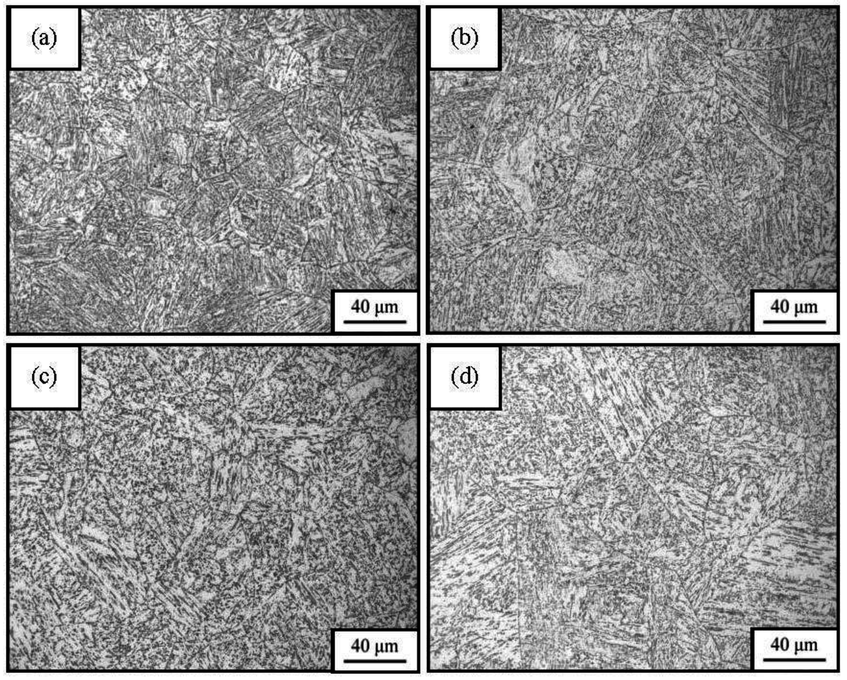
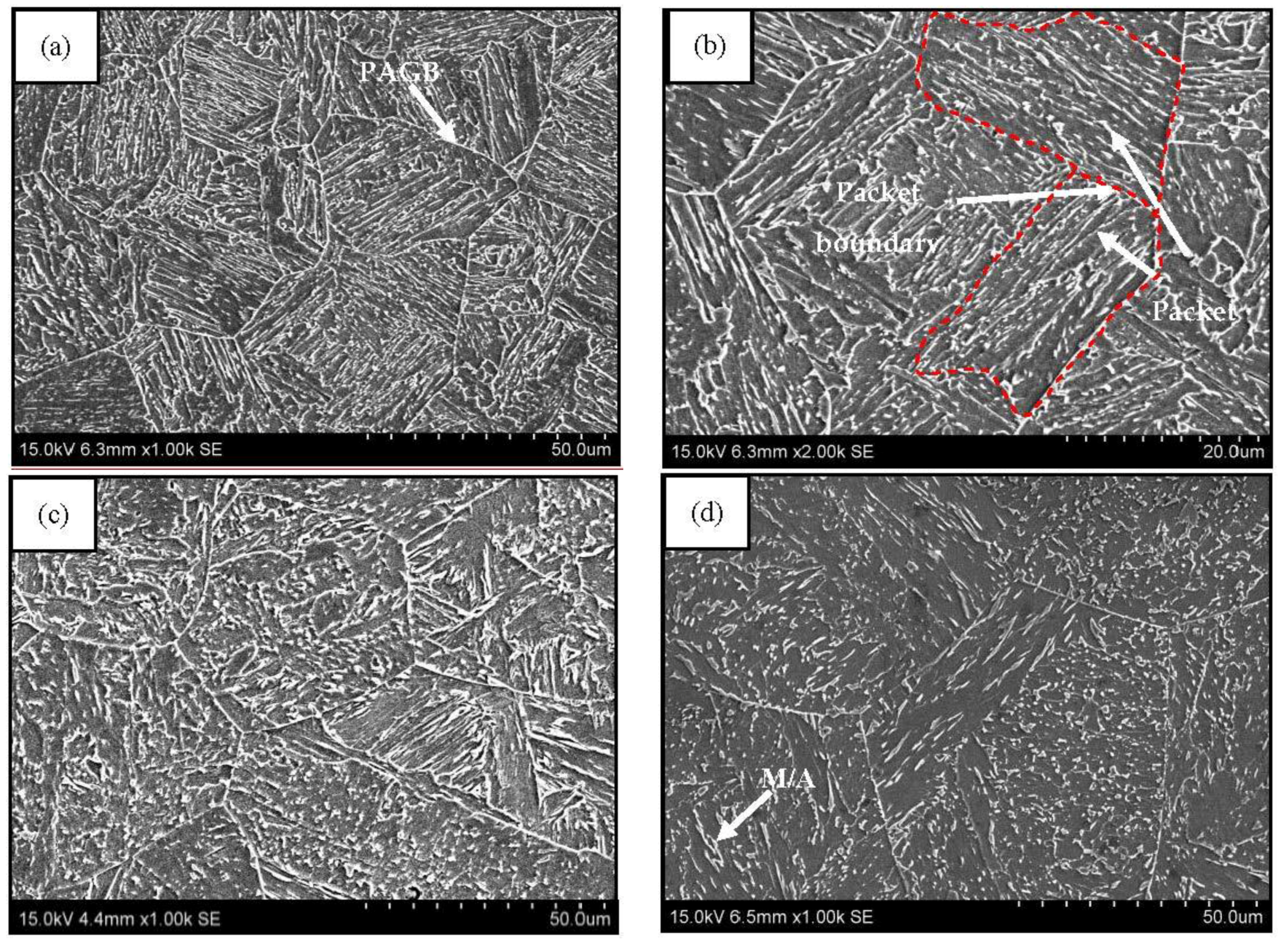
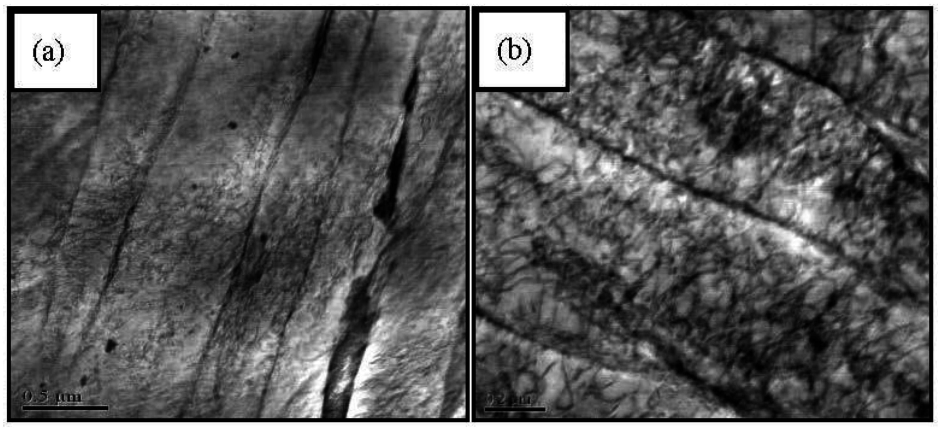
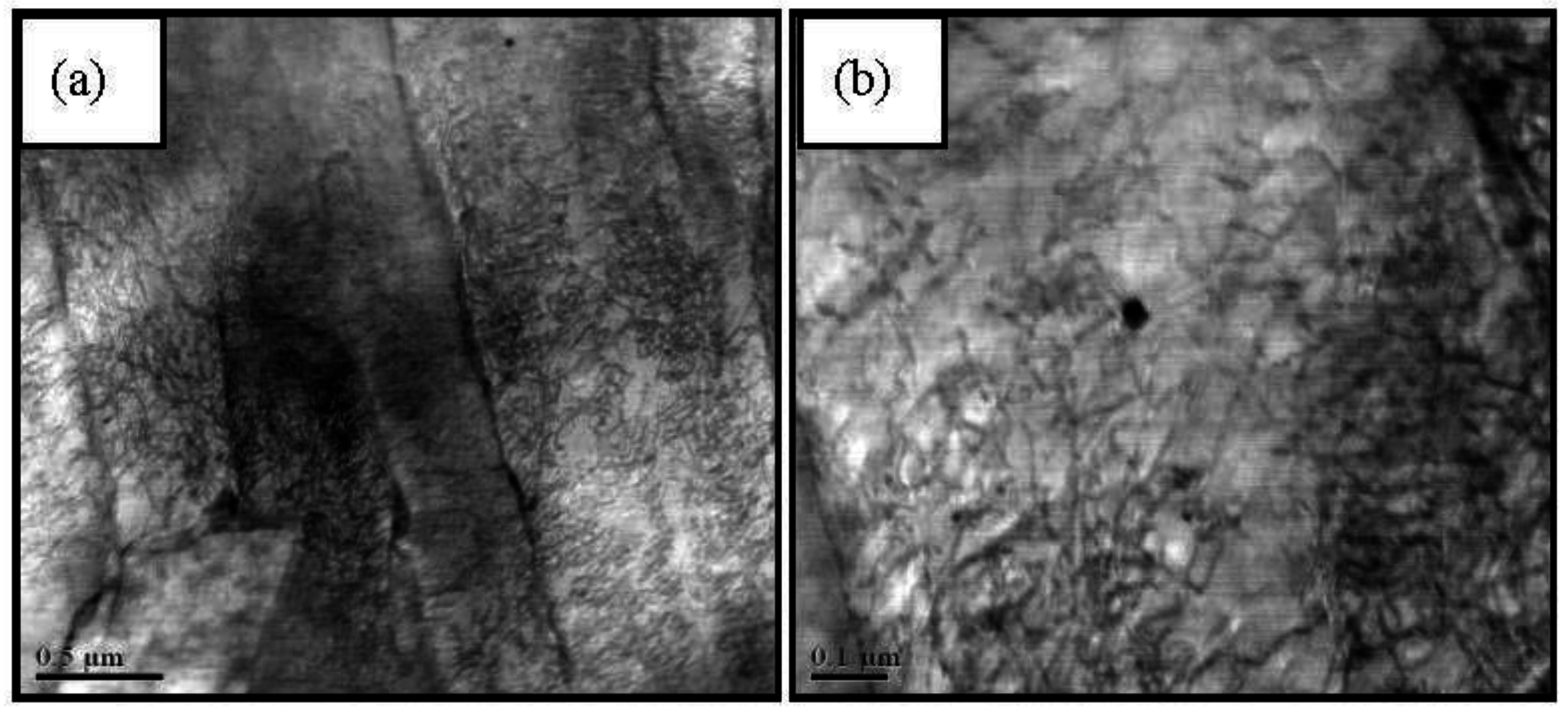
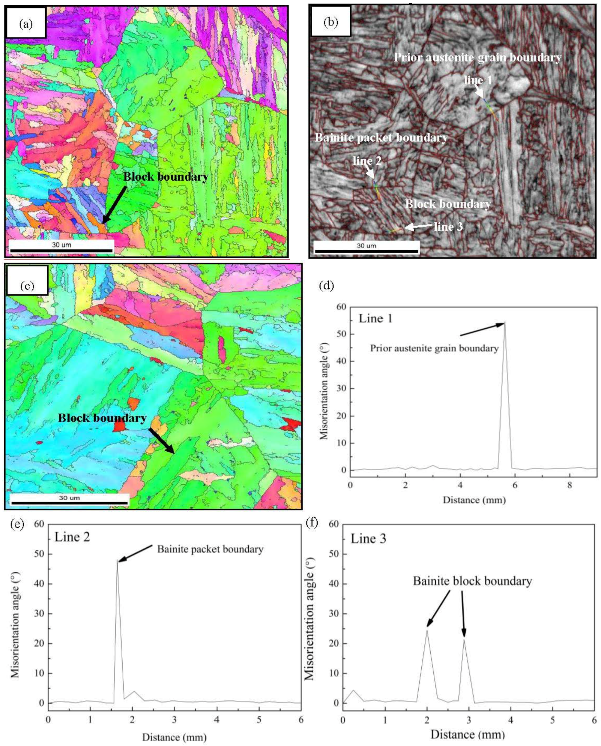
3.1. Microstructures of the Simulated CGHAZ

Optical micrographs (OM) of the specimens varying with welding heat input are shown in Figure 3. The transformed microstructures of the specimens with different welding heat inputs are predominately lath bainite and a relatively small amount of granular bainite. With the decreasing welding heat input, the lath bainite increases at the expense of granular bainite. In addition, the prior austenite grain is gradually refined (Figure 3), and the average size decreases from 68.6 to 30.4 μm (Table 2).
SEM micrographs of the specimens varying with welding heat input are shown in Figure 4. It is revealed that the prior austenite grain was divided into several bainite packets, and a minority of M/A constituent disperses at the bainite ferrite boundaries. With a decreasing welding heat input, the bainite packet are refined with an average size of bainite packet decreasing from 40.8 to 18.9 μm, and the amount of the M/A constituent, fM/A, decreases from 6.1% to 3.2%, as shown in Figure 4 and Table 2.
The block boundary cannot be revealed clearly by means of conventional OM and SEM until the occurrence of the EBSD technique. Recently, the block structure was successfully indicated with the assistance of EBSD for SEM and a definition of grain misorientation higher than 15° as the block boundary [14]. The EBSD misorientation maps of the specimens varying with welding heat input are shown in Figure 5. The bainitic block is indicated by arrows in Figure 5a,c, and the average block widths at different welding heat inputs are shown in Table 2. It is indicated that the average block width decreases from 16.2 to 8.6 μm as the welding heat input decreases from 60 to 30 kJ/cm. Moreover, the prior austenite grain and bainitic packet boundaries can also be recognized in the EBSD misorientation maps. The misorientation distributions between the neighboring prior austenite grain boundary, the bainite packet boundary, and the block boundary are measured by the highlight line method (Figure 5b), shown in Figure 5d–f, respectively. It is indicated that the prior austenite grain boundary (Line 1) and bainitic packet boundary (Line 2) have high misorientation angles near 55° and 48°, respectively, while the misorientation angle of the bainite block boundary (Line 3) is only near 23°.
Representative bright field TEM micrographs of the specimens with heat inputs of 30 kJ/cm and 60 kJ/cm are presented in Figure 6 and Figure 7, respectively. In general, the microstructure is predominantly composed of bainite ferrite laths with high density of dislocations based on TEM observations. It is revealed that bainite ferrite laths in the sample with lower heat input (Figure 6a) are much finer than in the sample with higher heat input (Figure 7a). Moreover, a higher density of dislocations (Figure 6b) are observed in the sample with lower heat input.

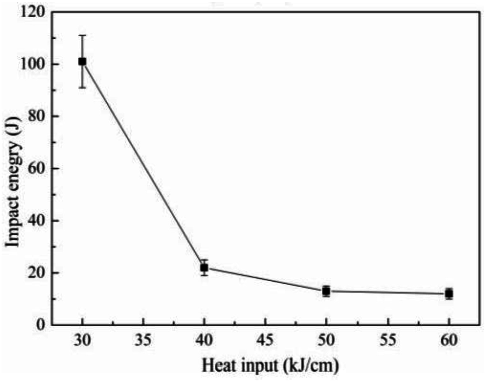
3.2. Charpy Impact Properties of the Simulated CGHAZ

The low-temperature (−20 °C) Charpy impact energies of specimens varying with welding heat input are shown in Figure 8. It is indicated that, with the heat input decreasing from 60 to 40 kJ/cm, the impact energy remains at a low level due to a relatively high amount of M/A constituents acting (Table 2) as the brittle phase [21,22]. However, it still slightly increases as a result of microstructure refinement (Figure 3, Figure 4 and Figure 5). When further decreasing the heat input to 30 kJ/cm, the impact energy is significantly improved simultaneously by even finer microstructures (Figure 3, Figure 4 and Figure 5) and a significant decrease in the amount of M/A constituents (Table 2). The impact energy stands for the resistance energy to fracture, and a higher impact energy indicates that the materials are more resistant to fracture, leading to the harder inducement and propagation of cracks [23].
The morphologies of the fracture surfaces of the Charpy impact specimens (tested at −20 °C) varying with heat input are shown in Figure 9. All fracture surfaces present cleavage fracture, and the average cleavage facet sizes of the specimens with different heat inputs are listed in Table 2. When the heat input is 60 kJ/cm, the cleavage facet size is 42.3 μm, calculated as the equivalent circle diameter related to the cleavage facet area. With the heat input decreased to 30 kJ/cm, the cleavage facet size remarkably decreases to 20.5 μm. Moreover, despite the cleavage facet, secondary cracks can also be observed in the SEM fractographs. It is revealed that the secondary crack in the sample with lower heat input (Figure 9a) is much shorter than that in the sample with higher heat input (Figure 9b), which indicates that the microstructure in the specimen with lower heat input is more resistant to crack propagation than the one with higher heat input.
In order to investigate crack propagation, the secondary cracks underneath the fracture surface of the impact samples were observed, as shown in Figure 10. Figure 10a reveals that the secondary crack firstly deviates at the prior austenite grain boundary (identified by the white arrow in Figure 10a), then propagates through the substructures (blocks) in the packet, and finally deflects at the boundary between the two packets (identified by the yellow arrow in Figure 10a). Figure 10b shows that the secondary cracks propagate through the block boundaries (identified by the white arrow in Figure 10b) directly without deviation, and then are arrested at the boundary between the two packets (identified by the yellow arrow in Figure 10b). Hence, it is indicated that the block boundary (a misorientation angle of 23°) could not impede the propagation of the cracks, while the packet boundary (a misorientation angle of 48°) and the prior austenite grain boundary (a misorientation angle of 55°) could effectively deflect the crack propagation direction or arrest the cracks in the test steel.

4. Discussion

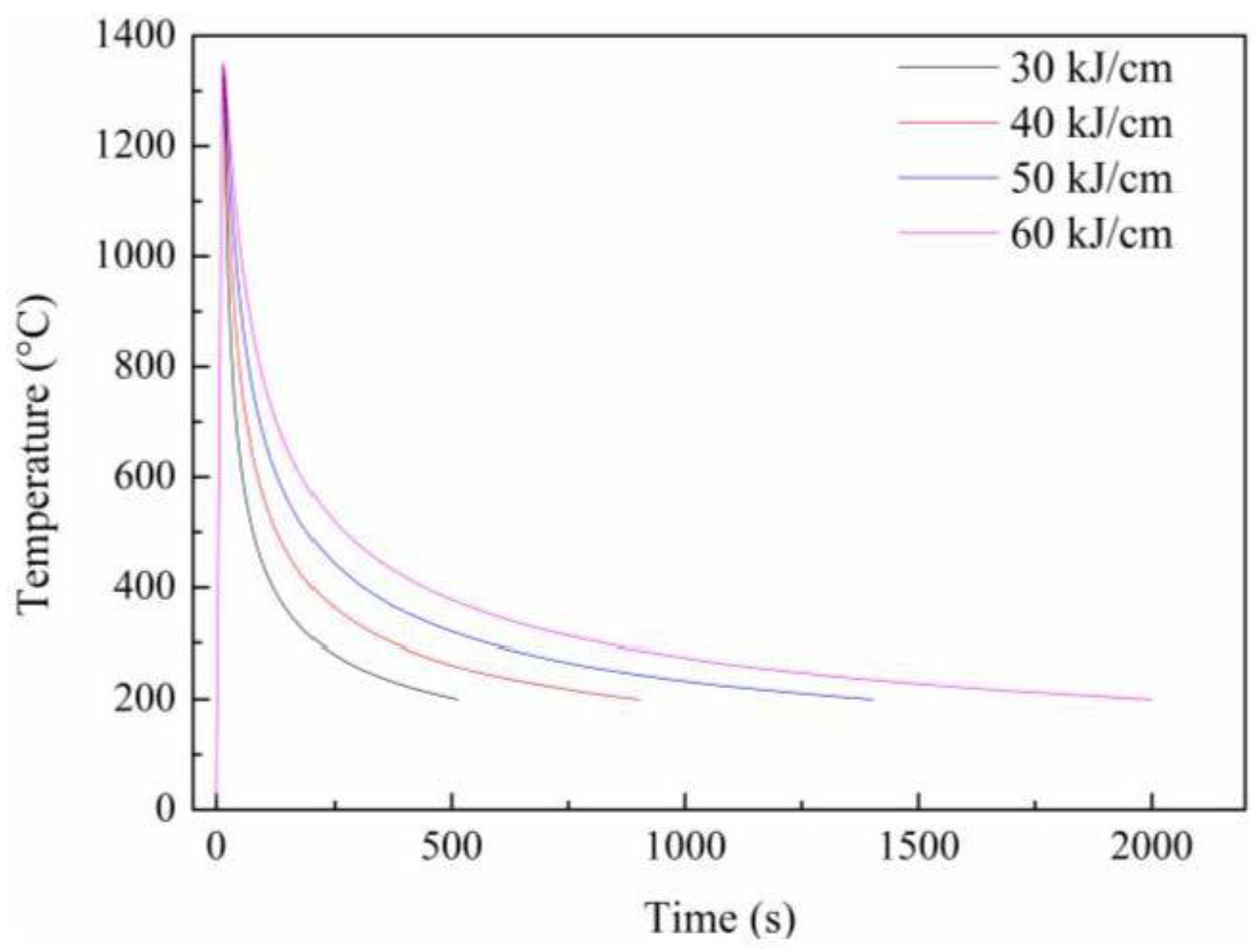
4.1. Microstructure Evolution during the Simulated Welding Thermal Cycle

The evolution of the final microstructure can be explained as follows. Coarse austenite grain will be formed when the specimen is reheated to 1350 °C. During the continuous cooling process, lath bainite ferrite nucleates, austenite (γ)/ferrite (α) interface moves forwardly, and supersaturated carbon in ferrite diffuses to the γ/α interface [24]. The untransformed austenite thus becomes carbon-enriched due to the partitioning of carbon. With the lowering of the transforming temperature, the remaining austenite transforms into lath bainite ferrite continuously, and the retained austenite is further carbon-enriched and fully stabilized until the transformation becomes thermodynamically impossible [25]. In the following cooling course, part of the carbon-enriched austenite could transform to martensite, and the retained austenite would coexist with the martensite.
Lath bainite is known as the typical transformation product in the CGHAZ [7]. With the decreasing welding heat input, i.e., the increasing cooling rate, prior austenite grains are significantly refined (Table 2) together with the increasing austenite grain boundaries density due to the shorter staying time in the high temperature zone (austenite zone). Moreover, the transformation start temperature decreases accordingly [26]. All these will result in a higher thermodynamic driving force for lath bainite formation [27], an increase in dislocation density in lath bainite [28], and a refinement of lath bainite ferrite, which is related to an increase in the nucleation rate and a decrease in grain growth [29].

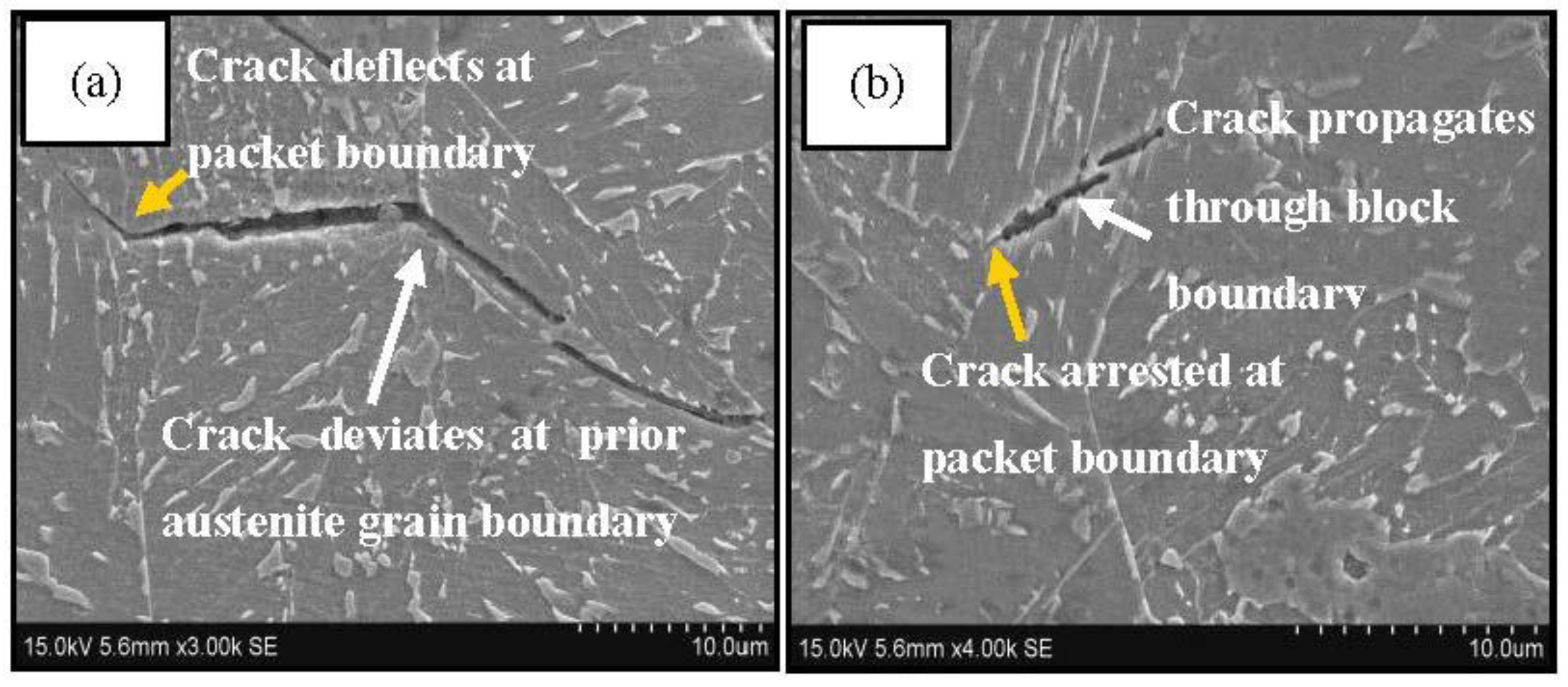
4.2. Effect of Grain Boundary on Impact Toughness in the Simulated CGHAZ

Grain boundary is well-known as the microstructure unit controlling the toughness of steels [14,30,31]. It owns high potential energy to impede crack propagation, and the increase of grain boundary density, namely the refinement of grain, can significantly improve the toughness of steels. Particularly, there are three kinds of grain boundaries in the CGHAZ of X90 pipeline steel: the prior austenite grain boundary, the bainite packet boundary, and the bainite block boundary. Moreover, in this study, the fracture mode for the specimens at all heat inputs is cleavage fracture; thus, the average cleavage facet size (Table 2) was measured and analyzed to better evaluate the effectiveness of different kinds of microstructure unit in control of impact toughness in the CGHAZ of X90 pipeline steel.
Figure 11a presents the linear relationship between the average cleavage facet size and average prior austenite grain size, and the fitting function is as follows:
d c = 2.2 + 0.57 d a
where dc is the average cleavage facet size, da is the average prior austenite grain size, and the correlation coefficient of this linear fit is 0.99.
The average cleavage facet size of the experimental steel processed with different heat inputs is in a good linear relation to the average prior austenite grain size (Figure 11a). Moreover, it is observed that the secondary crack deviates at the prior austenite grain boundary (identified by white arrow in Figure 10a), which indicates the prior austenite grain boundary could effectively impede the crack propagation. However, the average prior austenite grain size is nearly twice as much as the average cleavage facet size, suggesting that the prior austenite grain may not be the most effective microstructure unit in control of impact toughness in the CGHAZ of X90 pipeline steel.
Figure 11b presents the linear relationship between the average cleavage facet size and average bainite packet size, and the fitting function is as follows:
d c = 0.1 + 1.02 d p
where dc is the average cleavage facet size, dp is the average bainite packet size, and the correlation coefficient of this linear fit is 0.96.
The average cleavage facet size of the experimental steel processed with different heat inputs is in a good linear relation to the average bainite packet size (Figure 11b). Moreover, it is observed that the secondary crack deviates or can be arrested at the bainite packet boundary (identified by yellow arrow in Figure 10a,b, respectively), which indicates the bainite packet boundary could effectively impede the crack propagation or arrest the cracks. It should be further noted that the average cleavage facet size is nearly equal to the average bainite packet size, indicating that the bainite packet ought to be the most effective microstructure unit in control of impact toughness in the CGHAZ of X90 pipeline steel.
Figure 11c presents the linear relationship between the average cleavage facet size and average bainite block width, and the fitting function is as follows:
d c = 6.4 + 2.85 d b
where dc is the average cleavage facet size, db is the average bainite block width, and the correlation coefficient of this linear fit is 0.79.
Despite the relatively good linear fitting result, it is observed that the secondary crack propagates through the bainite block boundary (identified by white arrow in Figure 10b), which indicates the bainite block boundary could not effectively impede the crack propagation. Moreover, the average cleavage facet size is nearly triple as much as the average bainite block width, suggesting that the bainite block is not an effective microstructure unit in control of impact toughness in the CGHAZ of X90 pipeline steel.
Hence, it is indicated that the bainite packet is the most effective microstructure unit in control of impact toughness in the CGHAZ of X90 pipeline steel. Moreover, based on the mechanics model of cleavage fracture, the fracture stress σf can be expressed as [14,32]:
σ f = [ 4 E γ P ( 1 υ 2 ) d ] 1 / 2
where E, γP, and υ are all constants, which represents Young’s modulus, the plastic deformation energy, and the Poisson’s ratio, respectively, and d is the effective grain size, which corresponds to bainite packet size (dp) in this study.
The critical fracture stress represents the maximum external load the structures can undertake to keep materials from being fractured. The increasing fracture stress means that the materials becomes more resistant to fracture [14,31]. In this study, dp reduces significantly (Table 2) when decreasing the welding heat input, leading to the notable increase in the critical fracture stress. Therefore, with the decreasing welding heat input, the increasing impact toughness (Figure 8) is achieved as a result of the grain refinement (mainly packet refinement in this study) and the consequent increase of the critical fracture stress.
Several studies have been carried out to deal with the relationship between the impact toughness and the effective microstructure unit for lath bainite or lath martensite steels [14,17,19,33]. The studies by Wang et al. [14] and Rancel et al. [16] indicated that the packet boundaries can strongly hinder fracture propagation and can act as an effective microstructure unit for cleavage fracture. Moreover, in recent work by Yang et al. [18,34], they revealed that high angle boundary (including packet boundary) remarkably contributes to a good toughness of the CGHAZ in high-grade pipeline steel. The present results are in good agreement with the previous works above on the relationship between the impact toughness and the effective microstructure unit.

5. Conclusions

The microstructures and the impact toughness of X90 pipeline steel after a simulated thermal cycle with different heat inputs was investigated in this work. The major conclusions are summarized as follows:
  • The microstructure of the simulated CGHAZ is predominantly composed of lath bainite with different welding heat inputs. With the decreasing heat input, prior austenite grain, bainite packet, and block are all obviously refined.
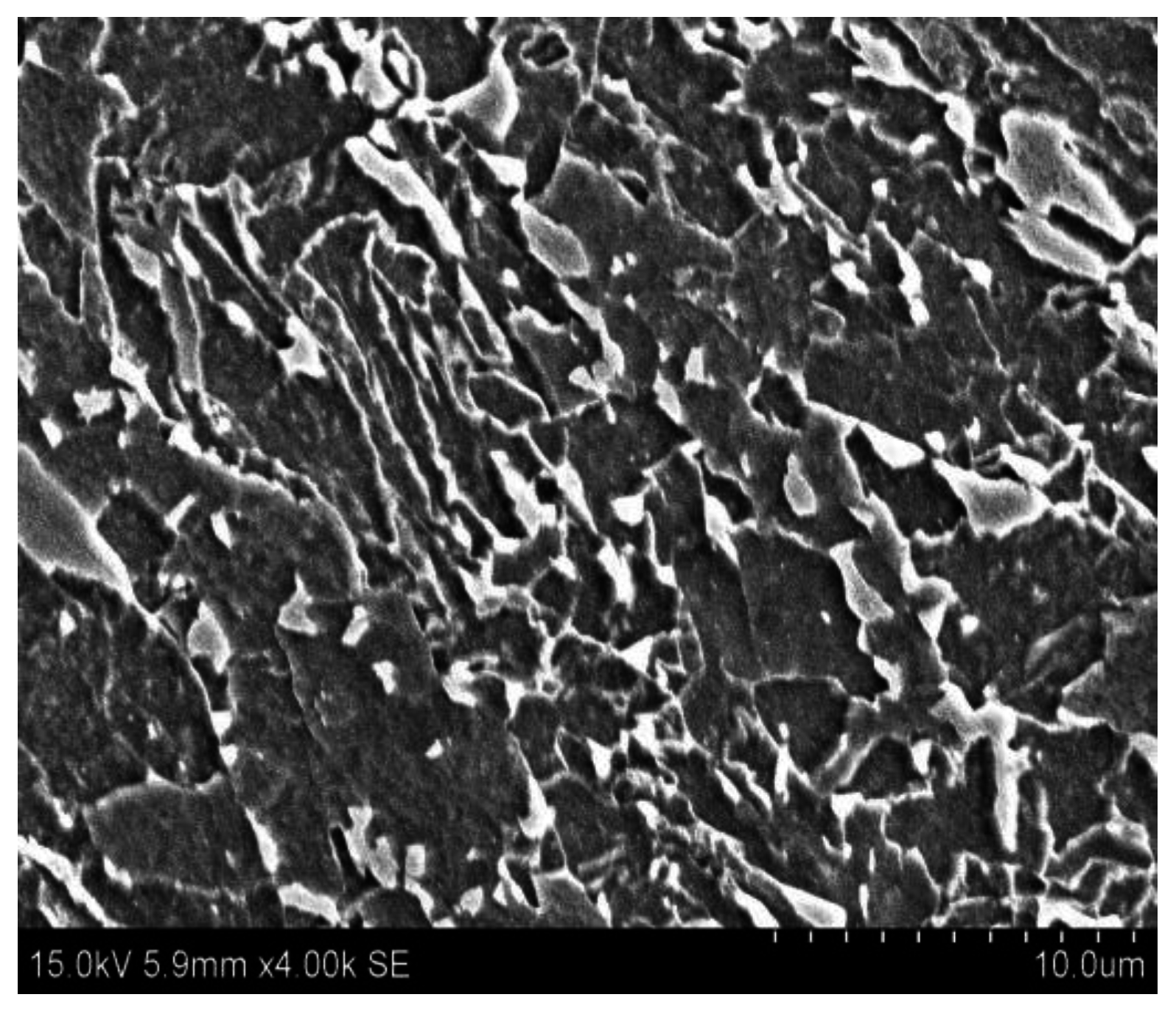
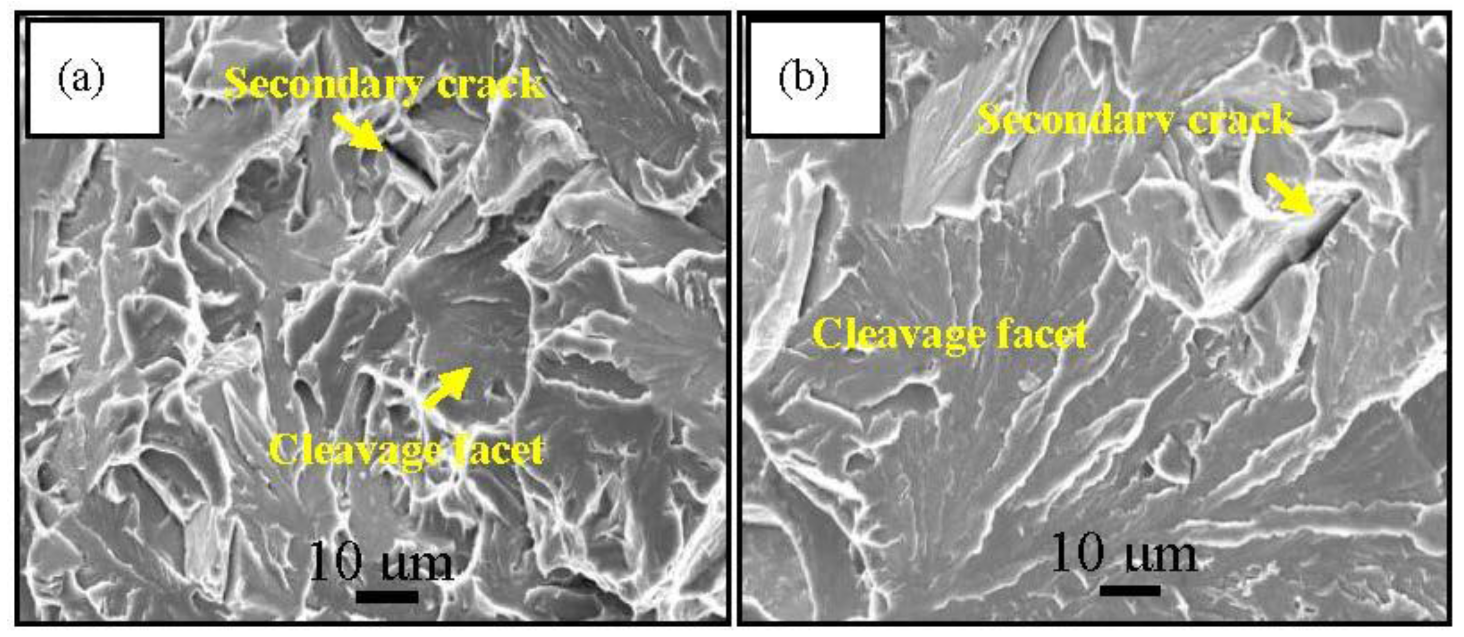
  • With the decreasing heat input, the impact toughness significantly improves. The fracture surfaces all present cleavage fracture for the samples with different heat inputs, and the average cleavage facet size decreases when the heat input is decreased.
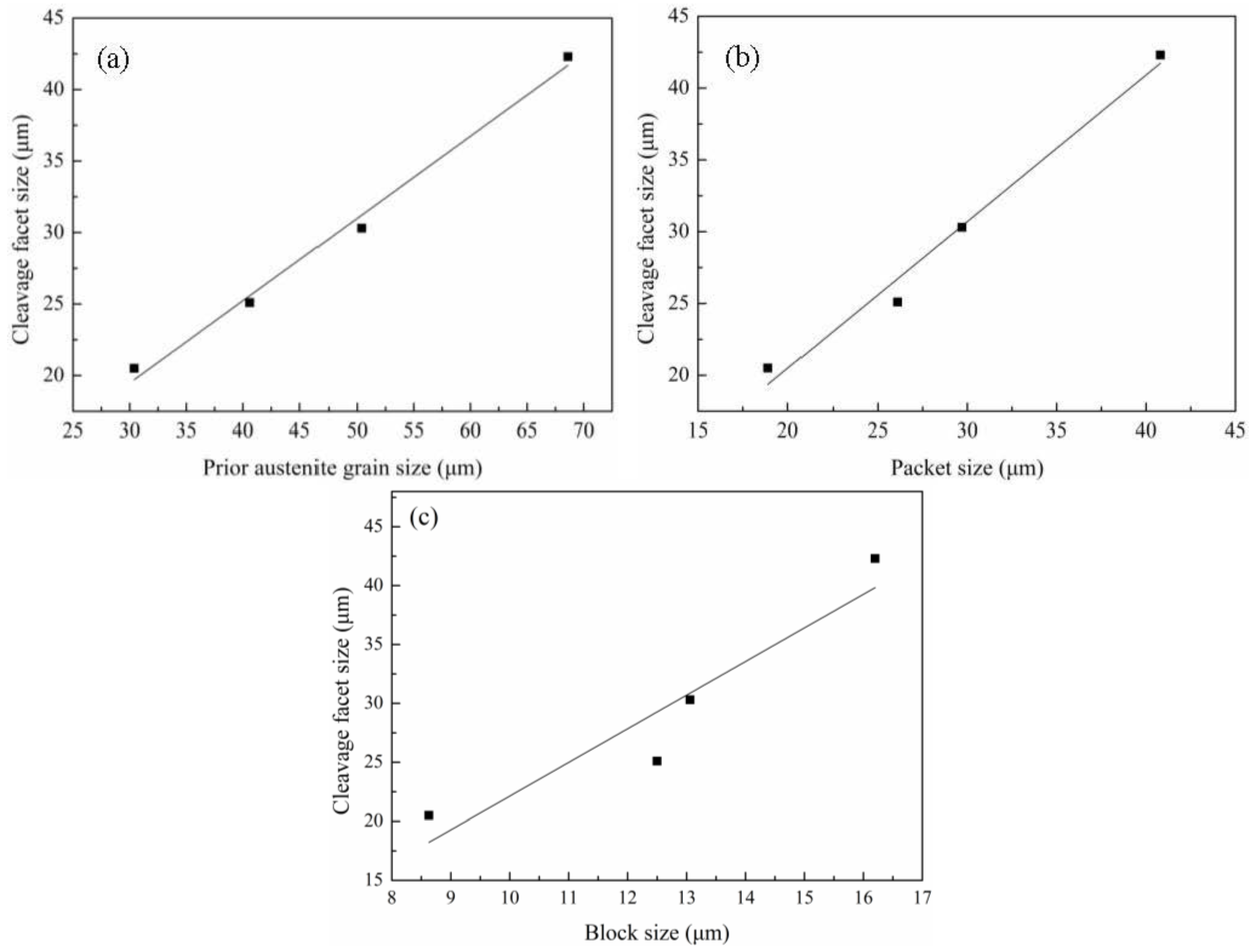
  • The average bainite packet size for the CGHAZ is nearly equal to the average cleavage facet size, and the bainite packet boundary can strongly impede the crack propagation, indicating that the bainitic packet is the most effective unit in control of impact toughness in the simulated CGHAZ of X90 pipeline steel.

Acknowledgments

This work was financially supported by the Research and Development Center of Wuhan Iron and Steel (Group) Company of China under the Contract No. 2014Z05, and by the National Natural Science Foundation of China (Grant No. 51471142 and No. 5167010961).

Author Contributions

Qingfeng Wang and Bin Guo conceived and designed the experiments; Lei Fan performed the experiments; Fucheng Zhang and Qian Wang analyzed the data; Zhibin Fu contributed analysis tools; Qingfeng Wang and Bin Guo wrote the paper.

Conflicts of Interest

The authors declare no conflict of interest.

References

  1. Shin, S.Y.; Hwang, B.; Lee, S.; Kim, N.J.; Ahn, S.S. Correlation of microstructure and charpy impact properties in API X70 and X80 line-pipe steels. Mater. Sci. Eng. A 2007, 458, 281–289. [Google Scholar] [CrossRef]
  2. Zhao, W.; Wang, W.; Chen, S.; Qu, J. Effect of simulated welding thermal cycle on microstructure and mechanical properties of X90 pipeline steel. Mater. Sci. Eng. A 2011, 528, 7417–7422. [Google Scholar] [CrossRef]
  3. Davis, C.L.; King, J.E. Cleavage initiation in the intercritically reheated coarse-grained heat-affected zone: Part I. Fractographic evidence. Metall. Mater. Trans. A 1994, 25, 563–573. [Google Scholar] [CrossRef]
  4. Hu, J.; Du, L.X.; Wang, J.J.; Gao, C.R. Effect of welding heat input on microstructures and toughness in simulated CGHAZ of V-N high strength steel. Mater. Sci. Eng. A 2013, 577, 161–168. [Google Scholar] [CrossRef]
  5. Wei, R.; Wu, K.M.; Gao, Z. Effect of Heat Input on Impact Toughness of Coarse-Grained Heat-Affected Zone of a Nb-Ti Microalloyed Pipeline Steel. Adv. Mater. Res. 2012, 538, 2026–2031. [Google Scholar]
  6. Li, R.; Zuo, X.; Hu, Y.; Wang, Z.; Hu, D. Microstructure and properties of pipeline steel with a ferrite/martensite dual-phase microstructure. Mater. Charact. 2011, 62, 801–806. [Google Scholar] [CrossRef]
  7. Lambert-Perlade, A.; Gourgues, A.F.; Pineau, A. Austenite to bainite phase transformation in the heat-affected zone of a high strength low alloy steel. Acta Mater. 2004, 52, 2337–2348. [Google Scholar] [CrossRef]
  8. Guo, A.; Misra, R.D.K.; Liu, J.; Chen, L.; He, X.; Jansto, S.J. An analysis of the microstructure of the heat-affected zone of an ultra-low carbon and niobium-bearing acicular ferrite steel using EBSD and its relationship to mechanical properties. Mater. Sci. Eng. A 2010, 527, 6440–6448. [Google Scholar] [CrossRef]
  9. You, Y.; Shang, C.; Chen, L.; Subramanian, S. Investigation on the crystallography of the transformation products of reverted austenite in intercritically reheated coarse grained heat affected zone. Mater. Des. 2013, 43, 485–491. [Google Scholar] [CrossRef]
  10. Sung, H.K.; Shin, S.Y.; Cha, W.; Oh, K.; Lee, S.; Kim, N.J. Effects of acicular ferrite on charpy impact properties in heat affected zones of oxide-containing API X80 linepipe steels. Mater. Sci. Eng. A 2011, 528, 3350–3357. [Google Scholar] [CrossRef]
  11. Zhu, Z.X.; Marimuthu, M.; Kuzmikova, L.; Li, H.J.; Barbaro, F. Influence of Ti/N ratio on simulated CGHAZ microstructure and toughness in X70 steels. Sci. Technol. Weld. Join. 2013, 18, 45–51. [Google Scholar] [CrossRef]
  12. Morito, S.; Tanaka, H.; Konishi, R.; Furuhara, T.; Maki, T. The morphology and crystallography of lath martensite in Fe-C alloys. Acta Mater. 2003, 51, 1789–1799. [Google Scholar] [CrossRef]
  13. Mateo, C.G.; Rivas, L.M.; Caballero, F.G.; Milbourn, D.; Sourmail, T. Vanadium effect on a medium carbon forging steel. Metals 2016, 6, 130. [Google Scholar] [CrossRef]
  14. Hu, H.; Xu, G.; Zhou, M.; Yuan, Q. Effect of Mo content on microstructure and property of low-carbon bainitic steels. Metals 2016, 6, 173. [Google Scholar] [CrossRef]
  15. Lee, S.; Kim, B.C.; Lee, D.Y. Fracture mechanism in coarse grained HAZ of HSLA steel welds. Scr. Metall. 1989, 23, 995–1000. [Google Scholar] [CrossRef]
  16. Kim, Y.M.; Kim, S.K.; Lim, Y.J.; Kim, N.J. Effect of microstructure on the yield ratio and low temperature toughness of linepipe steels. ISIJ Int. 2002, 42, 1571–1577. [Google Scholar] [CrossRef]
  17. Rancel, L.; Gómez, M.; Medina, S.F.; Gutierrez, I. Measurement of bainite packet size and its influence on cleavage fracture in a medium carbon bainitic steel. Mater. Sci. Eng. A 2011, 530, 21–27. [Google Scholar] [CrossRef]
  18. Zhang, C.; Wang, Q.; Ren, J.; Li, R.; Wang, M.; Zhang, F. Effect of martensitic morphology on mechanical properties of an as-quenched and tempered 25CrMo48V steel. Mater. Sci. Eng. A 2012, 534, 339–346. [Google Scholar] [CrossRef]
  19. You, Y.; Shang, C.; Nie, W.; Subramanian, S. Investigation on the microstructure and toughness of coarse grained heat affected zone in X-100 multi-phase pipeline steel with high Nb content. Mater. Sci. Eng. A 2012, 558, 692–701. [Google Scholar] [CrossRef]
  20. Barbaro, F.J.; Zhu, Z.; Kuzmikova, L.; Li, H.; Gray, J.M. Towards improved steel alloy designs for control of weld heat affected zone properties. In Proceedings of the BaoSteel Academic Conference, Shanghai, China, 4–6 June 2013.
  21. Li, C.; Wang, Y.; Han, T.; Han, B.; Li, L. Microstructure and toughness of coarse grain heat-affected zone of domestic X70 pipeline steel during in-service welding. J. Mater. Sci. 2011, 46, 727–733. [Google Scholar] [CrossRef]
  22. Moeinifar, S.; Kokabi, A.H.; Hosseini, H.R.M. Influence of peak temperature during simulation and real thermal cycles on microstructure and fracture properties of the reheated zones. Mater. Des. 2010, 31, 2948–2955. [Google Scholar] [CrossRef]
  23. Shanmugam, S.; Ramisetti, N.K.; Misra, R.D.K.; Hartmann, J.; Jansto, S.G. Microstructure and high strength-toughness combination of a new 700 MPa Nb-microalloyed pipeline steel. Mater. Sci. Eng. A 2008, 478, 26–37. [Google Scholar] [CrossRef]
  24. Zhao, M.-C.; Yang, K.; Xiao, F.-R.; Shan, Y.-Y. Continuous cooling transformation of undeformed and deformed low carbon pipeline steels. Mater. Sci. Eng. A 2003, 355, 126–136. [Google Scholar] [CrossRef]
  25. Wang, S.-C.; Yang, J.-R. Effects of chemical composition, rolling and cooling conditions on the amount of martensite/austenite (M/A) constituent formation in low carbon bainitic steels. Mater. Sci. Eng. A 1992, 154, 43–49. [Google Scholar] [CrossRef]
  26. Yakubtsov, I.A.; Poruks, P.; Boyd, J.D. Microstructure and mechanical properties of bainitic low carbon high strength plate steels. Mater. Sci. Eng. A 2008, 480, 109–116. [Google Scholar] [CrossRef]
  27. Furuhara, T.; Kawata, H.; Morito, S.; Maki, T. Crystallography of upper bainite in Fe-Ni-C alloys. Mater. Sci. Eng. A 2006, 431, 228–236. [Google Scholar] [CrossRef]
  28. Bhadeshia, H.K.D.H. Bainite in Steels; The Institute of Materials: London, UK, 1992; pp. 1–8. [Google Scholar]
  29. Olasolo, M.; Uranga, P.; Rodriguez-Ibabe, J.M.; López, B. Effect of austenite microstructure and cooling rate on transformation characteristics in a low carbon Nb-V microalloyed steel. Mater. Sci. Eng. A 2011, 528, 2559–2569. [Google Scholar] [CrossRef]
  30. Naylor, J.P.; Krahe, P.R. Cleavage planes in lath type bainite and martensite. Metall. Trans. A 1975, 6, 594–598. [Google Scholar] [CrossRef]
  31. Lan, L.; Qiu, C.; Zhao, D.; Gao, X.; Du, L. Microstructural characteristics and toughness of the simulated coarse grained heat affected zone of high strength low carbon bainitic steel. Mater. Sci. Eng. A 2011, 529, 192–200. [Google Scholar] [CrossRef]
  32. Daigne, J.; Guttmann, M.; Naylor, J.P. The influence of lath boundaries and carbide distribution on the yield strength of 0.4% C tempered martensitic steels. Mater. Sci. Eng. 1982, 56, 1–10. [Google Scholar] [CrossRef]
  33. Yasuto, F.; Yu-ichi, K. Study on critical CTOD property in heat affected zone of C-Mn microalloyed steel. Trans. Jpn. Weld. Soc. 1992, 32, 65–72. [Google Scholar]
  34. Hidenori, T.; Yutaro, S.; Atsushi, T.; Yu-ichi, K.; Koji, M.; Yusaku, T. Visualization and analysis of variant grouping in continuously cooled low-carbon steel welds. Metall. Mater. Trans. A 2014, 45, 3554–3559. [Google Scholar]
Figure 1. SEM (scanning electron microscope) image of X90 steel with multi-phase: granular bainite (black matrix) + M/A islands (white secondary phase). M/A—martensite/austenite.
Metals 06 00256 g001
Figure 2. Graph of the simulated thermal cycle on the Gleeble for the steel with different heat inputs.
Metals 06 00256 g002
Figure 3. The optical micrographs of the simulated thermal cycle treated specimens with different heat inputs: (a) 30 kJ/cm; (b) 40 kJ/cm; (c) 50 kJ/cm; (d) 60 kJ/cm.
Metals 06 00256 g003
Figure 4. SEM images of the specimens with different heat inputs: (a,b) 30 kJ/cm; (c) 40 kJ/cm; (d) 60 kJ/cm. PAGB—prior austenite grain boundary and M/A—martensite/austenite.
Metals 06 00256 g004
Figure 5. EBSD (electron backscattering diffraction) misorientation maps of X90 pipeline steel processed with different heat inputs: (a,b) 30 kJ/cm; (c) 60 kJ/cm. The black (a,c) and the red (b) grain boundary all represent high angle boundary with misorientation angles greater than 15°. Line 1 (d), line 2 (e), and line 3 (f) reveal the misorientation distributions between the neighboring prior austenite grain boundary, the bainite packet boundary, and the block boundary, respectively.
Metals 06 00256 g005
Figure 6. The TEM (transmission electron microscope) micrographs of the typical microstructure morphology in the specimen with heat input of 30 kJ/cm: (a) fine bainite ferrite lath; (b) dislocation distribution.
Metals 06 00256 g006
Figure 7. TEM micrographs of the typical microstructure morphology in the specimen with heat input of 60 kJ/cm: (a) broadening bainite ferrite lath; (b) dislocation distribution.
Metals 06 00256 g007
Figure 8. Charpy impact energies of the specimens with different heat inputs.
Metals 06 00256 g008
Figure 9. SEM images of fracture surfaces of the specimens with different heat inputs: (a) 30 kJ/cm; (b) 60 kJ/cm.
Metals 06 00256 g009
Figure 10. The secondary cracks underneath the fracture surface of impact samples: (a) cracks deviate at the prior austenite grain boundary and the bainite packet boundary; (b) cracks propagate through the bainite block boundary and are arrested at the packet boundary.
Metals 06 00256 g010
Figure 11. Cleavage facet size as a function of (a) prior austenite grain size; (b) bainite packet size; and (c) block width.
Metals 06 00256 g011
Table 1. Chemical compositions of the test steel (wt. %).
CSiMnPSCrCuMoNiNbVTiAl
0.060.301.900.0050.0020.360.260.190.140.090.020.020.03
Table 2. Results of the microstructure quantification.
Heat Input (kJ/cm)Block Width (μm)Packet Size (μm)PAG (μm)Cleavage Facet Size (μm)fM/A (%)
6016.240.868.642.36.1
5013.129.750.430.35.9
4012.526.140.625.15.3
308.618.930.420.53.2

