Article

Continuous Casting of Incoloy800H Superalloy Billet under an Alternating Electromagnetic Field

Key Laboratory of Electromagnetic Processing of Materials (Ministry of Education), Northeastern University, No. 3-11, Wenhua Road, Shenyang 110004, China
*
Author to whom correspondence should be addressed.
Metals 2016, 6(1), 2; https://doi.org/10.3390/met6010002
Submission received: 28 October 2015 / Revised: 10 December 2015 / Accepted: 15 December 2015 / Published: 23 December 2015
(This article belongs to the Special Issue Superalloys)

Abstract

:
We experimentally investigate the influence of an alternating electromagnetic field on the surface and internal qualities of Incoloy800H superalloy billets. The electromagnetic continuous casting experiments for Incoloy800H superalloy were successfully conducted and the billets (0.1 m × 0.1 m × 1.2 m) were obtained. We figure out that the high frequency (20.4 kHz) electromagnetic field which is applied in the mould region can improve the surface quality of Incoloy800H superalloy billet remarkably; the depth of oscillation mark decreases from 1.2 mm (without electromagnetic field) to 0.3 mm (with electromagnetic field). The internal quality of the billet was studied using a variety of characterization techniques. The low frequency (5 Hz) electromagnetic field which is applied in the second cooling region can improve the internal quality; the region of the equiaxed grain increases from 2.45% (without electromagnetic field) to 41.45% (with electromagnetic field). Furthermore, macro- and micro-segregation are suppressed and the TiN inclusion number is decreased as well.

Graphical Abstract

1. Introduction

Incoloy800H superalloy (UNS N08810) is an austenitic Fe-Ni-Cr superalloy with excellent strength and resistance to oxidation and carburization, particularly under high-temperature conditions. The alloy is widely used in equipment that experiences long-term exposure to high temperatures and corrosive atmosphere, e.g., pigtails, radiant tubes and intermediate heat exchangers (IHX).
The corrosion behavior of Incoloy800H superalloy in supercritical water (374 °C, 22.1 MPa) was investigated [1] and the results showed that an oxidation process was observed as the primary corrosion behavior. Further research on this oxidation behavior, along with its mechanisms, in the vicinity of three different zones (containing the substrate, heat-effected zone and the melt zone) in dry and wet air conditions was conducted [2]. The results showed that the oxidation kinetics of three different zones followed the parabolic-rate law in dry and wet air. However, in wet air, the oxidation behavior experienced two different kinetics stages, consisting of an initial mass-gain stage followed by a second mass-loss stage. For the Incoloy800H superalloy welding parts which were processed by the method of laser shocking peening (LSP), the study of the microstructure and the residual stresses were carried out [3]. The mechanism of the grain refinement was due to twinning matrix formation and th strain-induced grain boundary cracking. Furthermore, the LSP process-welded joints exhibited high compressive and uniform distribution residual stress. The neutron diffraction method was also used to determine the residual stresses [4], e.g., for an 8 mm Incoloy800H weld. The optimization of the diffusion welding process for Incoloy800H alloy was studied by numerical simulation [5]. Proper welding conditions were suggested, namely a temperature of 1423 K for an hour with an applied pressure of 5 MPa. Compression tests were conducted to investigate the hot deformation behavior of Incoloy800H superalloy at 1000 °C [6] and 750 °C [7], respectively. For temperatures above 1000 °C, a distinct change in slope of the linear fit curve regarding flow stress and temperature can be observed. For a temperature of 750 °C, the influence of the aging pre-treatment (for 0 h, 5 h, 10 h, 20 h and 50 h) is discussed in detail. The results revealed that the peak stress decreased whilst the aging time was increased. A further test regarding the relationship between fatigue crack growth (FCGR) and the external load ratios was conducted on Incoloy800H alloy at 750 °C [8]. As the load ratio increased, the crack growth increased as well. Through the thermo-mechanical process (TMP), the microstructure evolution, specifically of grain boundaries of Incoloy800H superalloy, was studied [9]. The results showed that the thermo-mechanical process can also introduce nanoscale precipitates in the matrix. Further research on the effect of TMP on the grain boundary character distribution (GBCD) in Incoloy800H was carried out [10]. The coincidence-site lattice boundaries increased with the pre-deformation level of the samples. For a highly deformed Incoloy800H superalloy, the nucleation and growth behavior were discussed [11]. The results showed that the oriented nucleation played a significant role in determining the final annealing texture. The dynamic strain aging (DSA) behavior in Incoloy800H superalloy was characterized under the condition of the strain rate in the range of 10−4 to 10−7 and temperatures between 295 K to 673 K [12]. It showed that, at temperatures above 473 K, the load serrations in Incoloy800H superalloy occurred over a wide range of strain rates. The tensile and creep-fatigue properties of Incoloy800H superalloy at a high temperature were investigated [13]. It was observed that the combined creep fatigue damage at 800 °C decreased with the decreasing total strain.
As seen in the short literature review above, most of the recent research focuses on the treatment and the post-processing of Incoloy800H superalloy, for better mechanical properties. The mechanical properties are determined by the surface and internal qualities of the product. Therefore, the manufacturing process of Incoloy800H superalloy billet is vital to obtaining an Incoloy800H alloy product with better mechanical properties. Electroslag remelting (ESR) is a secondary metal processing route for controlling the microstructure and chemical refining of the nickel-based superalloy [14]. For a higher production rate and lower production cost, continuous casting (CC) is an ideal technique for producing Incoloy800H superalloy billet. Continuous casting can remarkably increase the manufacturing efficiency; however, due to the special chemical composition of the alloy, the presence of defects, such as longitudinal cracks [15,16], can severely influence the quality of the whole Incoloy800H product. Electromagnetic casting (EMC) has been successfully applied to a large amount of metals to improve the surface and internal quality of the billet, even for some magnesium alloys and superalloy; e.g., Mg-Al-Zn-Ca alloy [17], IN100 superalloy [18] and Incoloy800H superalloy [19]. This is mainly because of the effect of electromagnetic force during the solidification process of the alloy. However, the application of the electromagnetic continuous casting technique to Inocoly800H superalloy is rare to see. Clearly, this shall be the task which will be completed in this paper. Our purpose is first to produce the Incoloy800H superalloy billet using the technique of electromagnetic continuous casting (EMCC). Secondly, we shall try to determine the influence of the alternating electromagnetic field on the surface and the internal quality of Incoloy800H superalloy. The influence of the electromagnetic field is represented by the two Incoloy800H superalloy continuous casting billets obtained through the contrast experiments: without (Set I) and with electromagnetic field (Set II), respectively.
The outline of the present paper is as follows. The experimental procedure is introduced in Section 2. In Section 3.1, the surface quality of the Incoloy800H continuous casting billet is discussed. In Section 3.2, the internal quality of the billet, including the macro and microstructure of the specimen (in Section 3.2.1), the macro and microsegregation (in Section 3.2.2) and the inclusion of TiN (in Section 3.2.3) are discussed, respectively. The main conclusions are summarized in Section 4.

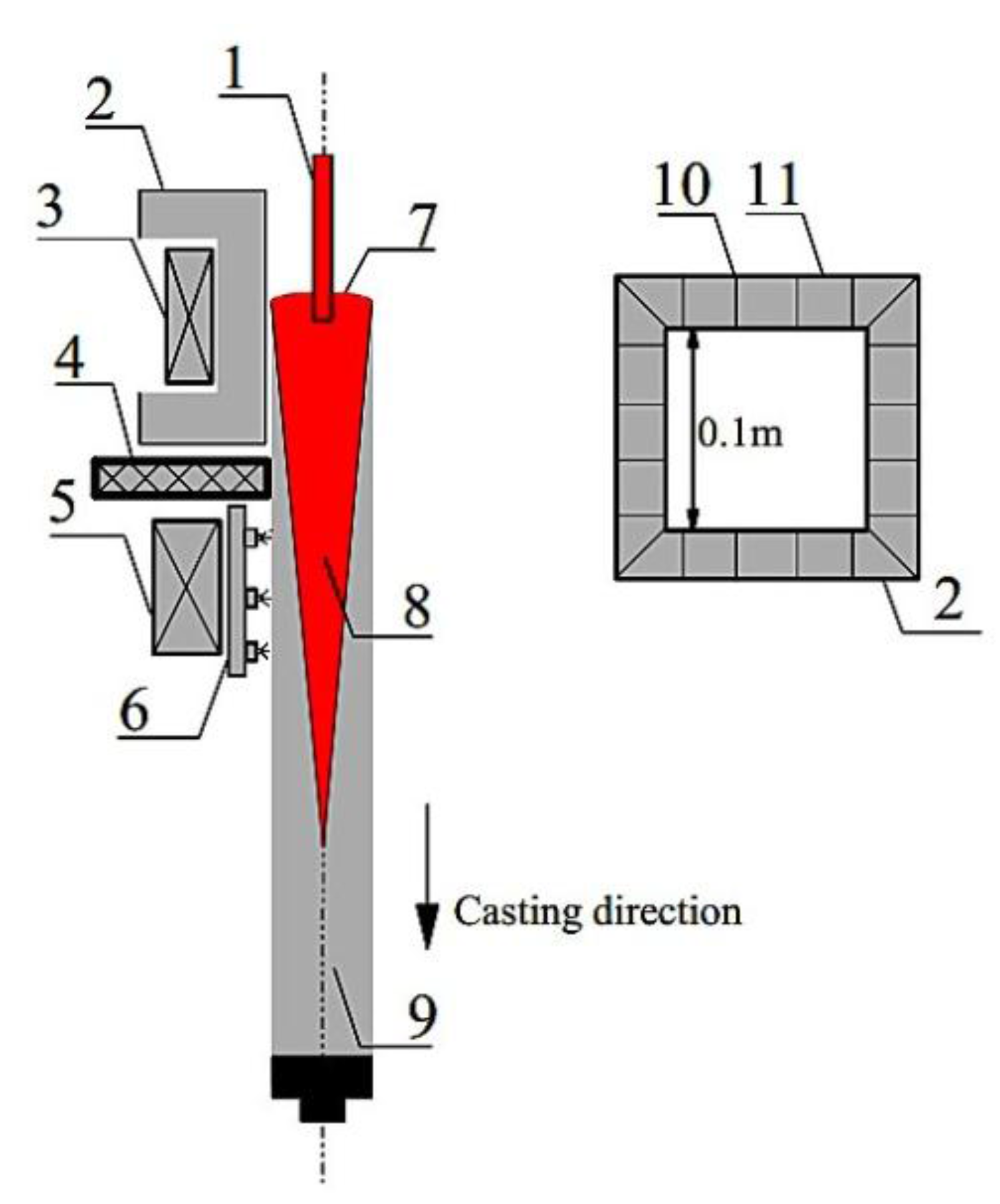
2. Experimental Procedure

The Incoloy800H superalloy is selected as a working liquid metal in the present research. The reason for this selection had been discussed in the Section 1. Table 1 shows the chemical composition of the superalloy we used in the present research. Figure 1 is the schematic representation of the electromagnetic continuous casting system. Due to its symmetrical nature, only half of the whole system was drawn. In Figure 1, (3) and (5) denote the electromagnetic continuous casting coil and the stirring coils, respectively. The theories of electromagnetic continuous casting and electromagnetic stirring (EMS) were thoroughly discussed by Vives [20] and Moffatt [21]. Therefore, we shall not discuss those theories in detail here. The alternating currents for EMCC and EMS are 1310 A and 350 A, respectively. The frequencies are 20.4 kHz and 5 Hz, respectively.
Table 1. Chemical composition for the Incoloy800H superalloy (in wt. %).
ElementCarbonSiliconManganesePhosphorusChromiumNickelTitaniumAluminumIron
(C)(Si)(Mn)(P)(Cr)(Ni)(Ti)(Al)(Fe)
wt. %0.080.520.80.02320.1330.880.520.2846.76
Figure 1. Schematic representation of the EMCC system (not scaled). (1) Nozzle, (2) mould, (3) high frequency induction coil for electromagnetic continuous casting (EMCC), (4) working platform, (5) electromagnetic stirring system (EMS), (6) water spray system, (7) meniscus, (8) liquid core, (9) EMCC billet (10) mould slit, and (11) mould segment.
Metals 06 00002 g001
The Incoloy800H superalloy (melting point: 1658 K) is first melted by a medium frequency furnace to 1700 K with a protective argon atmosphere. The temperature is captured by a B-type platinum rhodium thermocouple. The molten alloy is then poured into an EMCC copper mould (inner dimension: 0.1 m × 0.1 m). The EMCC mould has 20 slits in order to allow the high frequency electromagnetic field to permeate into the centre of the mould and act on the molten alloy. An ISP-200 kW super-sonic frequency power supply, with a frequency range from 10 kHz to 50 kHz, is used. Once the molten alloy free surface reaches the pre-set location, a casting speed is applied to the continuous caster and the experiment starts. Two sets of experiments are carried out: continuous casting without (Set I) and with (Set II) electromagnetic fields, respectively. The experimental conditions and operating parameters for both sets are shown in Table 2. In order to evaluate the influence of the electromagnetic field, the casting temperature, speed, cooling flows rate, mould oscillation frequency and amplitude are identical in Set I and II. For the Set II, the EMS is applied throughout the experiment. The magnetic flux density, which is due to the EMS system, is around 0.081 T with EMS current and frequency at 350 A and 5 Hz, respectively. However, the EMCC is only applied in a later stage of the experiment. The reason for this is that it is better for us to exclude the influence of the EMCC on the internal quality whilst we carry out the comparison study between Set I and II. Two billets with dimensions of 0.1 m × 0.1 m × 1.2 m are obtained from Set I and II, respectively.
Table 2. Experimental conditions and operating parameters for Set I and II.
ParametersSet ISet II
EMCC current, A01310
EMCC frequency, kHz020.4
EMS current, A0350
EMS frequency, Hz05
Casting speed, m/min0.60.6
Mould oscillation frequency, cpm3030
Mould oscillation amplitude, m0.0120.012
Mould cooling water flow rate, m3/h6.46.4
Secondary cooling water flow rate, m3/h3.03.0
Mould dimension, m0.1 × 0.1 × 0.40.1 × 0.1 × 0.4
Mould wall thickness, m0.030.03
Slit number, -2020
Slit height, m0.40.4
Slit width, m0.00050.0005
The depth of the oscillation mark is adopted to represent the surface quality of Incoloy800H superalloy billets. For the internal quality, the macrostructure of the cross-section of the billets is obtained after the samples were etched with the mixture etching agent. The microstructure morphology is investigated by using the OLYMPUS SZX16 microscope (OLYMPUS, Tokyo, Japan) and the grain size and the equiaxed grain fraction are estimated according to the ASTM standard [22]. The macrosegregation of carbon composition is captured by Leco CS844 infrared carbon-sulfur analyzer (Leco, San Jose, MO, USA) and the microsegregation of all chemical compositions was studied by Electron Probe Micro-analyzer (JXA-8530F EPMA, Shimadzu, Kyoto, Japan). The morphology of TiN was observed by Field-Emission Scanning Electron Microscope (JSM-7100F SEM, ZEISS, Jena, Germany) with an Energy Dispersive Spectrometer (EDS, ZEISS, Jena, Germany), and the number of TiN inclusion was captured by the inverted research microscope (Leica DMI5000M, Lecia, Barnack, Germany).

3. Results and Discussion

We first focus on the surface quality of the electromagnetic continuous casting billets of the Incoloy800H superalloy in Section 3.1 and then turn our attention to their internal quality in Section 3.2.

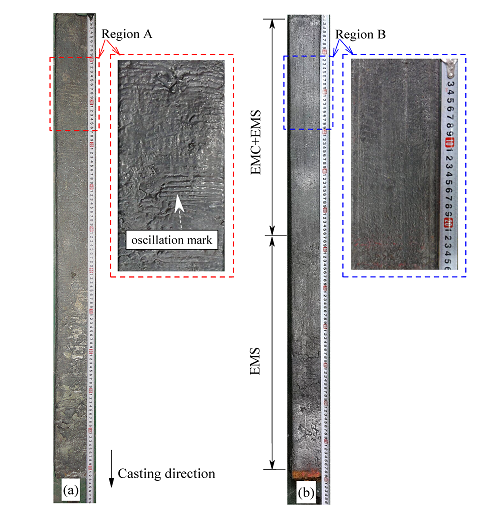
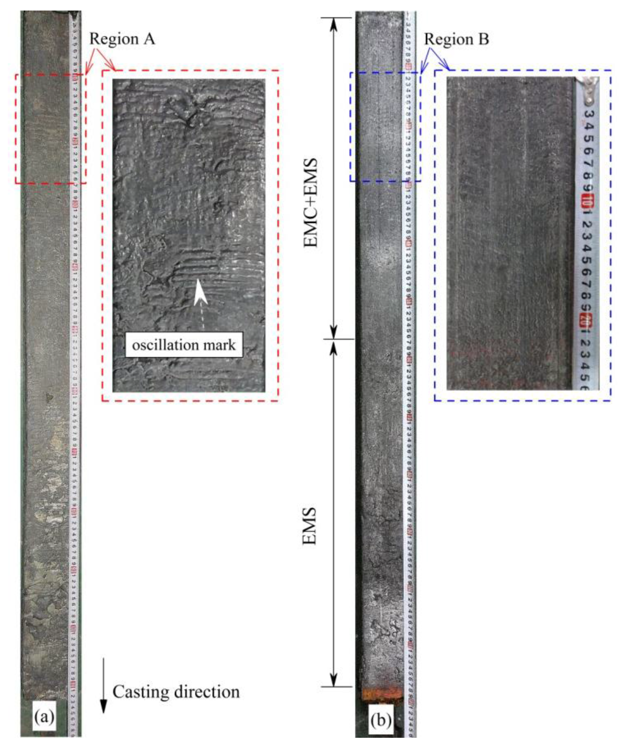
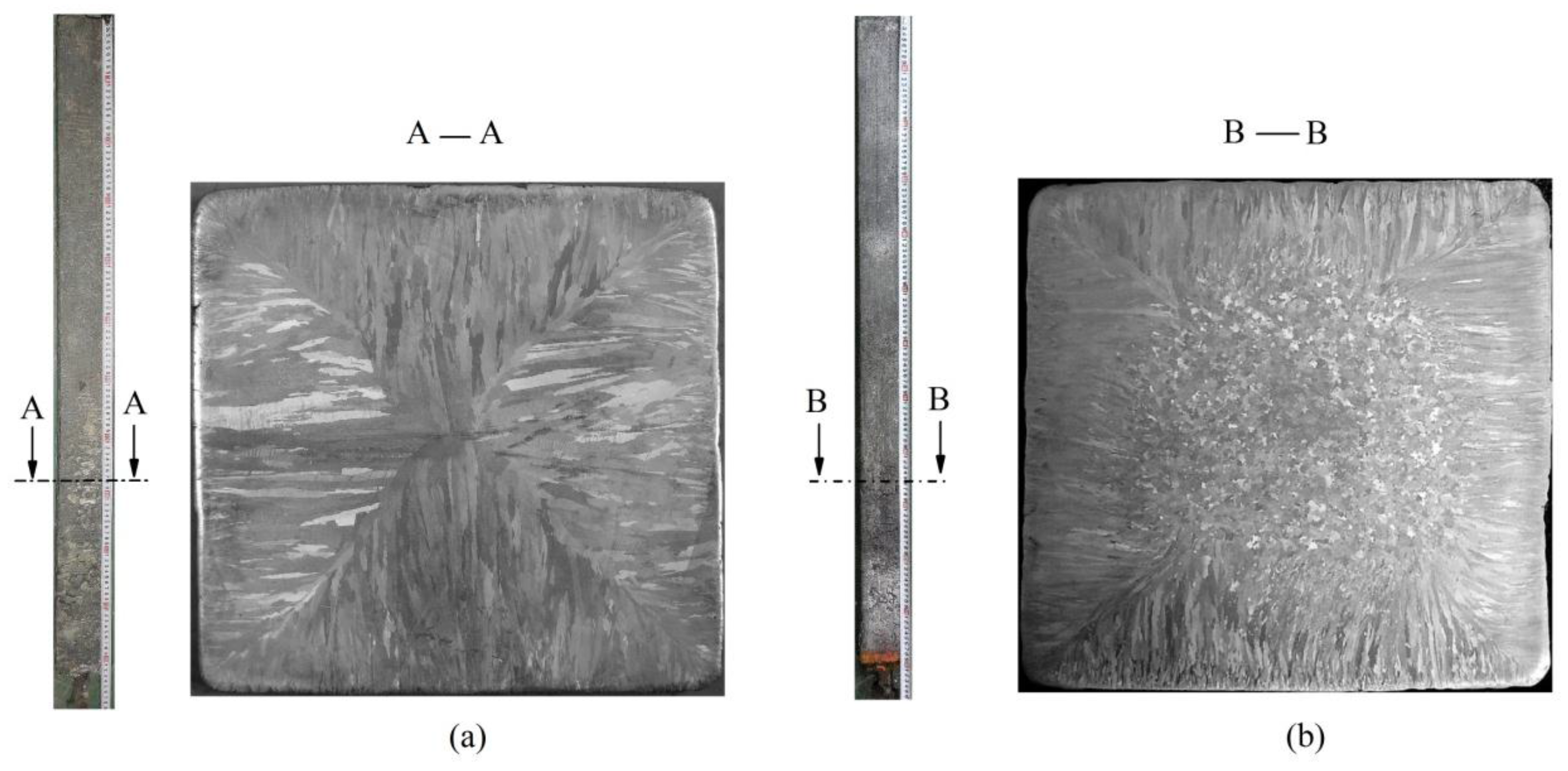
3.1. Surface Quality

Figure 2a,b shows the surface topographies of the billets obtained from Set I and II, respectively. It is clearly shown that the surface quality is highly improved by applying the high frequency electromagnetic field: the average depths of the oscillation marks decreased from 1.2 mm to 0.3 mm.
The mechanism for this improvement of the surface quality is similar to that for the other metals. The alternating current generates the alternating magnetic field with the same frequency as the initial current. The alternating magnetic field then generates the induced current in both the molten alloy and the mould segments. With the interaction of the magnetic field and the induced current in the molten alloy, the Lorentz force is generated with the direction pointing to the centre of the EMCC mould. The Lorentz force then reduces the contact pressure on the inner surface of the mould so that decreases the friction force between the molten alloy and the mould. This behavior improves the lubrication conditions dramatically so that the oscillation marks are obviously suppressed.
The improvement of the surface quality of the billet indicates that the EMCC technique also works on the Incoloy800H superalloy, which was not reported in the previous research.
Figure 2. The surface topographies of Incoloy800H superalloy billets. Billets obtained from (a) Set I and (b) Set II. The depths of the oscillation marks decreased from 1.2 mm to 0.3 mm due to the effect of the alternating electromagnetic field.
Metals 06 00002 g002

3.2. Internal Quality

The internal quality of the billet is evaluated by the investigation of the macro and microstructure (Section 3.2.1), the segregation (Section 3.2.2) and the TiN inclusion (Section 3.2.3).

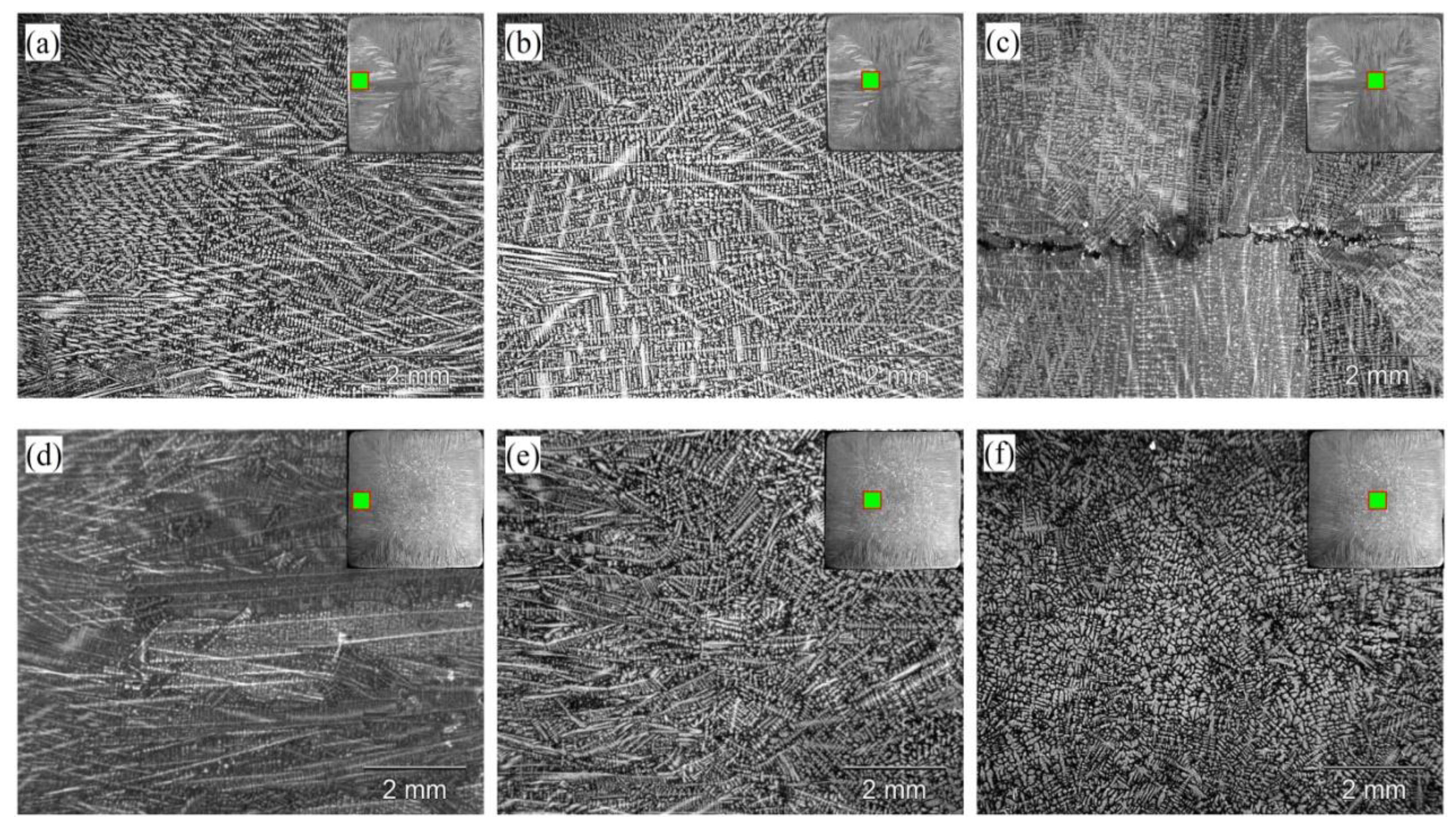
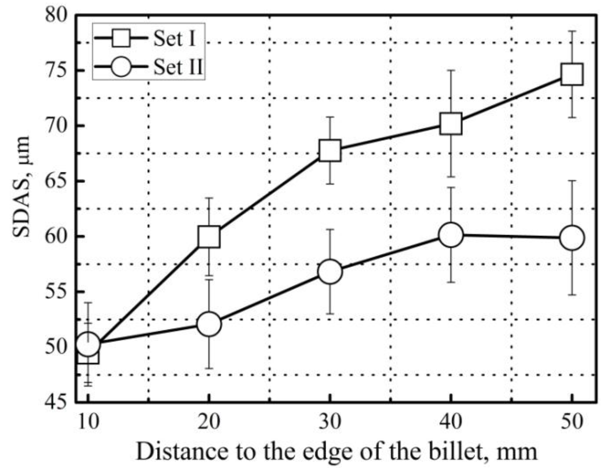
3.2.1. EMS on the Macro- and Microstructure

Figure 3 shows the cross-section macrostructure morphologies of the billets obtained from Set I (a) and II (b). With the aim of investigating the influence of EMS on the macrostructure of the Incoloy800H superalloy, for Set II, the aiming specimen for investigating should be obtained at the location when the EMCC current is at rest. The results show that the application of EMS can enlarge the region of the equiaxed grain from 2.45% to 41.45%, and can refine the equiaxed grain size significantly, from 10.83 mm to 1.28 mm.
A further study of EMS effect on Incoloy800H superalloy is conducted by investigating the microstructure. Three locations, edge, 1/4 width and 1/2 width (centre) of the billet cross-section, are selected for both specimens. The microstructure is obtained by using a DW/T-400 stero microscope and the microstructure morphologies at the selected locations are shown in Figure 4. For the specimen obtained from Set I, at the beginning of the solidification stage, a thin layer is formed by large numbers of tiny equiaxed dendrites (Figure 4a). The reason for the existence of the tiny equiaxed dendrites region is due to the large temperature gradient between the mould and the solidification front. This temperature gradient enforces a heat transfer process and results in a quick solidification. The tiny equiaxed dendrites grow rapidly with random orientation. For the 1/4 width region, some dendrites with a growing direction parallel to the temperature gradient (perpendicular to the mould wall) develop into the unidirectional columnar dendrites towards the centre of the billet, as shown in Figure 4b. In this region, coarse columnar dendrites are found. These unidirectional columnar dendrites continue to develop until they reach the centre of the specimen. Due to the symmetric features, the unidirectional columnar dendrites originated from all directions meet in the vicinity of the 1/2 width (centre of the specimen) region. The coarse equiaxed dendrites are observed, compared to the tiny equiaxed, as shown in Figure 4c.
Figure 3. Macrostructure morphology of the billet cross-section: (a) Set I and (b) II.
Metals 06 00002 g003
Figure 4. Microstructure of the billet: (ac) represent the location of edge, 1/4 width and 1/2 width of the specimen obtained from Set I, respectively; (df) represent the location of edge, 1/4 width and 1/2 width of the specimen obtained from Set II, respectively.
Metals 06 00002 g004
Once the EMS is applied, the solidification behavior proceeds in the same manner as that of Set I near the edge region. The tiny equiaxed dendrites region appears (Figure 4d). However, the development of the coarse columnar dendrites which are parallel to the temperature gradient direction is interrupted by a forced convection which is generated due to EMS. The interruption behavior can be represented by the appearance of the dendrite arms at the solidification front. The dendrite arms are remelted or broken into fragments, and the length of primary dendrite arm decreases. This results in the appearance the random growing direction of the coarse columnar dendrites, as shown in Figure 4e. In the centre of the billet, a large number of fine equiaxed dendrites are formed (Figure 4f).
For the specimens obtained in Set I and II, the variation of the secondary dendrite arm spacing (SDAS) is also investigated, as shown in Figure 5. It is clear shown that the SDAS is remarkably decreased when the EMS is applied. For the Incoloy800H superalloy, this phenomenon can be understood as follows: the Lorentz force originated from EMS results in the movement of the molten alloy. This movement is accompanied by a heat/mass transfer. The dendrite arms are remelted. The fragments which depart from the original dendrite can become an effective nucleus region and increase the nucleation rate. Furthermore, the movement of the fluid flow can render the temperature field uniform and decrease the temperature gradient through this forced convection behavior. This can increase the heat transfer process from the liquid core of the billet to the mould. These factors result in the decrease of the SDAS and grain size and enhance the transformation from columnar grain to equiaxed grains.
Figure 5. Variations of the secondary dendrite arm spacing (SDAS) with the distance from the edge to the centre of specimen.
Metals 06 00002 g005

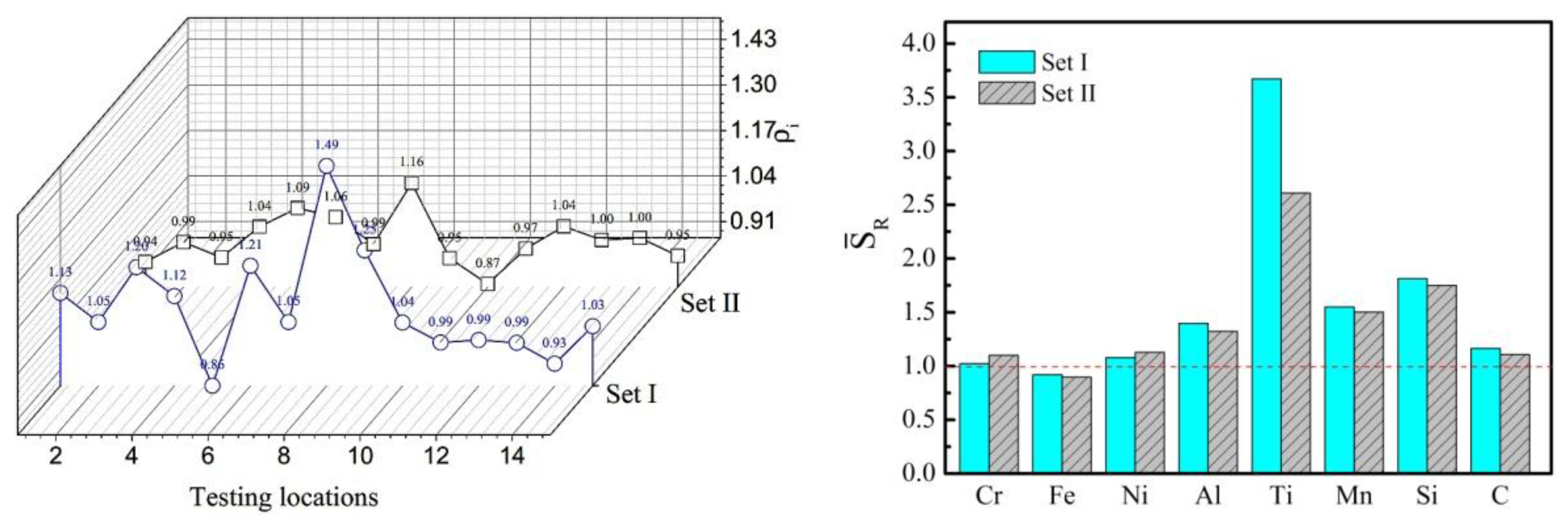
3.2.2. EMS on the Segregation

Another major occurrence in solidification stage is the change in melt chemistry. Segregation is important in that it alters physical and mechanical properties: the segregation of the carbon composition can result in the potential cracks. For the macrosegregation, the two specimens without and with EMS obtained in Set I and II, are drilled 15 holes (diameter φ = 5 mm) with an internal of 6.25 mm from one edge to the other, respectively. The chips are collected for elemental analysis and the carbon segregation index ρi is defined as follows:
ρ i = C i C ¯
where Ci the carbon content at point i, i ∈ [115], and C ¯ is the average carbon content of the 15 testing points. The level of microsegregation is evaluated by the segregation ratio, SR, which is defined as follows:
S R = C I D C D C
where CID and CDC are the concentrations in the interdendritic region and dendrite core, respectively. In the present research, 5 locations at the interdendritic region and dendrite core were selected, respectively. Therefore, 5 segregation ratios were obtained in the vicinity of the testing region. The average segregation ratio S R ¯ is defined as follows:
S R ¯ = j 5 S R
and was adopted. The positive and negative macrosegregation respectively: microsegregation) are defined when ρi > 1 (respectively: S R ¯ > 1) and ρi < 1 (respectively: S R ¯ < 1), respectively.
The distribution of ρi along the middle line of the specimens (Set I and II) and the average microsegregation ratio S R ¯ for each elements are shown in Figure 6 (left) and (right), respectively. For the macrosegregation, as shown in Figure 6 (left), the positive segregation of C elements reaches the maximum level of ρi = 1.49 in the vicinity of the centre region for the specimen obtained without EMS (Set I). For the specimen obtained from Set II (with EMS), the maximum ρi is decreased to 1.16. For the microsegregation of the specimen obtained in Set I, as shown in Figure 6 (right), most elements exhibit positive segregation behavior and indicate that these elements are enriched in the interdendritic region. It is clearly shown that the EMS reduces the microsegregation level for all the compositions. For Incoloy800H superalloy, the Ti element is the most serious and it reaches the peak value of S R ¯ is 3.67 without EMS and decreases to 2.75 when EMS is applied.
Figure 6. (Left) Variations of the content of carbon segregation index ρi for different testing locations; (Right) Microsegregation ratio distribution without (set I) and with (set II) EMS.
Metals 06 00002 g006
The reason for the central segregation of carbon composition without EMS has been thoroughly discussed. Here, it would more interesting to focus on the mechanism of how the EMS decreases the central segregation of Incoloy800H superalloy in continuous casting. The solidification structure of the molten alloy is formed by the development of the dendrites. In the mushy zone, the density of the solute, e.g., C, increases due to the selective crystallization feature. The solute concentration obtains a higher value in the vicinity of the dendrite core compared to that near the interdendritic regions because of the different solubility of solute in the solid and liquid. It may be worth mention that the mushy zone is assumed to be a saturated porous medium that offers frictional resistance toward fluid flow. Permeability in the mushy zone can be defined as following [23]:
K = d 2 g l 3 180 × ( 1 g l ) 2
where K is the permeability, d is the representative size in the dendritric structure and gl is the volume of fraction of the liquid. When EMS is not applied, the columnar dendrite grows towards to the centre of the billet. The higher value of the K causes the enrichment of the solute in the centre cross-section of the specimen. When EMS is applied, the permeability K is decreased due to the forced convection which is caused by the Lorentz force. This can be proofed by the decreasing of the SDAS values, as we discussed in Figure 5. The decreasing of the K uniforms the solute redistribution process and results in the decreasing of the segregation.
For the microsegregation, it is recognized as a result of a partition behavior of solute from the liquid phase to the solid phase. The solute partition coefficient k is defined as:
k i = C s i C l i
where C s i and C l i are the concentration of solute i in solid and liquid, respectively. The effective partitioning coefficient expressed as [24]:
k e = k k + ( 1 k ) R δ D L
where here DL is solute diffusion coefficient in liquid, R is growth rate, k is the equilibrium partitioning coefficient, and δ is the boundary layer thickness ahead of liquid/solid interface, respectively. When EMS is applied, the solidification time and the diffusion rate are decreased due to the increasing of the growing rate of nucleation, the forced convection originated from EMS constantly scours the solute-rich liquid and accelerates the homogenization of the solute elements in the remaining liquid. The increasing R results in the ke becoming closer to 1, which indicates the decrease of the microsegregation between the dendrite core and the interdendritic regions.

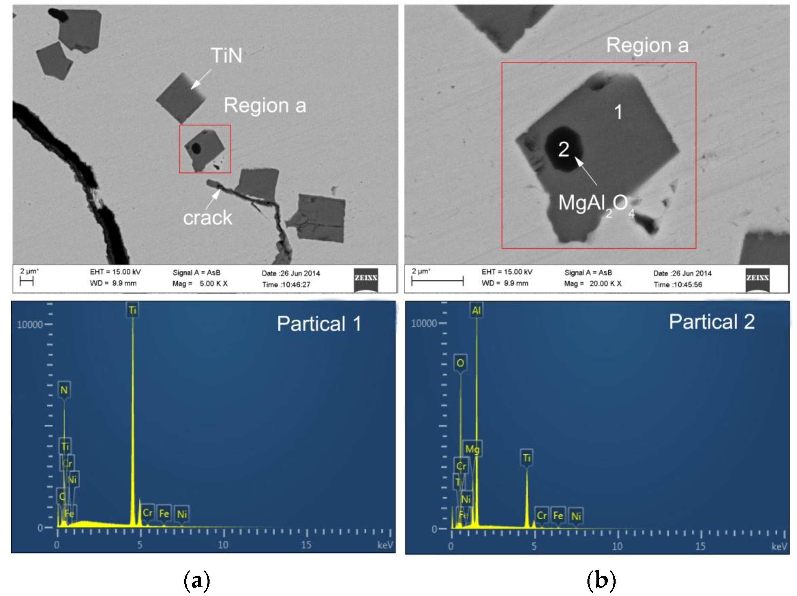
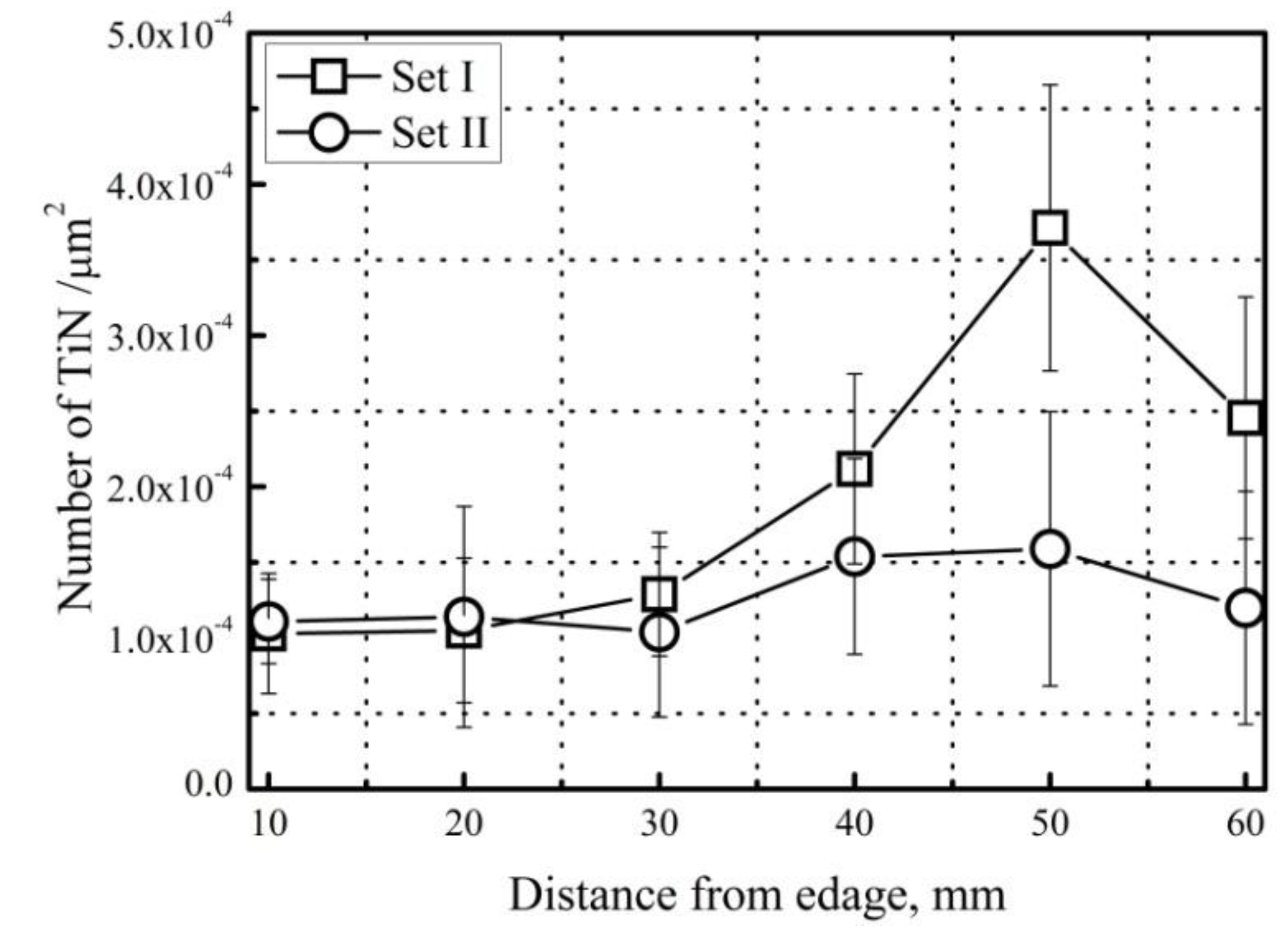
3.2.3. TiN Inclusion

As we discussed in Section 3.2.2, the microsegregation of Ti element cannot be ignored because it plays an important role in the formation and growth of TiN. The inclusion of TiN will significantly affect the mechanical properties. Incoloy800H superalloy is more susceptible to the formation of TiN inclusions because of its relatively high level of Ti content. Therefore, the elimination of TiN inclusion is considered to be an important issue for improving the internal quality of Incoloy800H superalloy billet.
Figure 7 shows the TiN inclusion for the specimen obtained by Set I. For the billet of Incoloy800H superalloy obtained from Set I, the TiN inclusion has a typically cubic or rectangular-prim morphology, and some TiN inclusions have a black nucleus. In the figure, the existence of the crack in the vicinity of TiN inclusion is observed. The crack is because of the large degree of misfit between TiN inclusion and matix. The results also shows that the nucleus identified by SEM-EDS is MgAl2O4 spinel which was produced by the addition of the refractory material MgO and Al2O3 and can serve as a nucleation site for the formation of TiN. The range of TiN size is 1.85 to 10.94 µm.
The TiN inclusion number is estimated at the six locations with an internal of 10 mm from the edge to the centre of the cross-section. Each location is observed within thirty random fields of view at a magnification of 500× by the optical microscope (Leica DMI5000M, Lecia, Barnack, Germany). Figure 8 shows the variations of the number of the TiN inclusion along the radius direction of Incoloy800H billets. The results show that, for the specimens obtained from Set I and II, the TiN inclusion number shows no major differences in the vicinity of edge of the cross-section. This is because the initial solidification shell (5 mm to 10 mm) is already formed when the billet enters the EMS system covered region. The Lorentz force cannot handle the solidified shell. As the value of the distance from the specimen edge is increased, the number of TiN inclusion is significantly reduced for the specimen obtained in Set II compared to that in Set I, especially near the centre of the cross-section region, as shown in Figure 8.
Figure 7. SEM images of an Incoloy800Hsuperalloy sample obtained in Set II. (a) TiN with and without nucleus; (b) TiN with nucleus.
Metals 06 00002 g007
Figure 8. Variations of the TiN inclusion number along the radius direction of Incoloy800H superalloy billet in Set I and II.
Metals 06 00002 g008
The main reasons for the decrease of TiN inclusion by applying EMS can be understood as follows: firstly, as we discussed in Section 3.2.2, EMS can suppress the microsegregation of most compositions. Therefore, this obviously decreases the chance for the composition Ti and N to form TiN inclusion. Secondly, the rotating molten alloy produces turbulent vortex which can carry the TiN inclusions to the centre of the specimen. At the centre region, forced convection caused by EMS will promote the collision and coagulation of these TiN inclusions for forming TiN clusters. Due to the fact that the density of TiN is less than that of the surrounding molten alloy, TiN inclusions will float toward the upper part of the billet due to the buoyancy force, which escaped the solidifying matrix. Furthermore, the TiN clusters will move vertically upward more quickly than the fine TiN inclusions. These results cause a decrease in the TiN inclusion number when EMS is applied.

4. Conclusions

We successfully carried out an electromagnetic continuous casting experiment for Incoloy800H superalloy. With the aim of comparing the influence of the alternating electromagnetic field on the surface and internal qualities of the billet, a continuous casting experiment for Inconloy800H without an electromagnetic field was conducted as well. For both billets, the surface and internal qualities, which were represented by the depths of oscillation marks and macro- and microstructure segregations and inclusions, respectively, were investigated. The results can be broadly summarised as follows.
The electromagnetic continuous casting experiment was carefully designed and successfully carried out. An Incoloy800H superalloy billet with dimensions of 0.1 × 0.1 × 1.2 m was obtained. For the surface quality of the billet, the depth of the oscillation mark significantly reduced from 1.2 mm to 0.3 mm while the high frequency (20.4 kHz) electromagnetic field was applied. For the internal quality, the macrostructure is refined with the low frequency (5 Hz) of the electromagnetic field. The fraction of the equiaxed grain increased from 2.45% to 41.4%, and the equiaxed grain size decreased from 10.83 mm to 1.28 mm. The segregation and the number of the TiN inclusions were suppressed as well.

Acknowledgments

This work was financially supported by the National Nature Science Foundation of China (No. 50834009), the Key Project of the Ministry of Education of China (No. 311014) and the Programme of Introducing Talents of Discipline to Universities (the 111 Project of China, No. B07015). The authors would also like to thank the referees for their work, which has contributed to this paper.

Author Contributions

Fei Wang and Engang Wang conceived and designed the experiments; Fei Wang, Anyuan Deng and Xiujie Xu performed the experiments; Fei Wang and Engang Wang analyzed the data; Anyuan Deng and Engang Wang contributed reagents/materials/analysis tools; Fei Wang, Lintao Zhang and Engang Wang contributed to writing and editing of the manuscript.

Conflicts of Interest

The authors declare no conflict of interest.

References

  1. Tan, L.; Allen, T.T.; Yang, Y. Corrosion behavior of alloy 800H (Fe-21Cr-32Ni) in supercritical water. Corros. Sci. 2011, 53, 703–711. [Google Scholar] [CrossRef]
  2. Chen, W.S.; Kai, W.; Tsay, L.W.; Kai, J.J. The oxidation behavior of three different zones of welded Incoloy 800H alloy. Nucl. Eng. Design 2014, 272, 92–98. [Google Scholar] [CrossRef]
  3. Chen, X.; Wang, J.; Fang, Y.; Madigan, B.; Xu, G. Investigation of microstructures and residual stresses in laser peened Incoloy800H weldments. Opt. Laser Technol. 2014, 57, 159–164. [Google Scholar] [CrossRef]
  4. Chen, X.; Zhang, S.; Wang, J.; Kelleher, J. Residual stresses determination in a 8 mm Incoloy800H weld via neutron diffraction. Mater. Design 2015, 76, 26–31. [Google Scholar] [CrossRef]
  5. Mizia, R.E.; Clark, D.E.; Glazoff, M.V.; Lister, T.E.; Trowbridge, T.L. Optimizing the diffusion welding process for alloy 800H: Thermodynamic, diffusion modeling, and experimental work. Metall. Mater. Trans. A 2013, 44, 154–161. [Google Scholar] [CrossRef]
  6. Cao, Y.; Di, H. Research on the hot deformation behavior of a Fe-Ni-Cr alloy (800H) at temperatures above 1000 °C. J. Nucl. Mater. 2015, 465, 104–115. [Google Scholar] [CrossRef]
  7. Cao, Y.; Di, H.; Misra, R.D.K. The impact of aging pre-treatment on the hot deformation behavior of alloy 800H at 750 °C. J. Nucl. Mater. 2014, 452, 77–86. [Google Scholar] [CrossRef]
  8. Kim, D.J.; Seo, D.Y.; Tsang, J.; Yang, J.H.; Lee, J.H.; Saari, H.; Seok, C.S. The crack growth behavior of Incoloy 800H under fatigue and dwell-fatigue conditions at elevated temperature. J. Mech. Sci. Technol. 2015, 26, 2023–2027. [Google Scholar] [CrossRef]
  9. Tan, L.; Rakotojaona, L.; Allen, T.R.; Nanstad, R.K.; Busby, J.T. Microstructure optimization of austenitic alloy 800H (Fe-21Cr-32Ni). Mater. Sci. Eng. A 2011, 528, 2755–2761. [Google Scholar] [CrossRef]
  10. Akhiani, H.; Nezakat, M.; Sanayei, M.; Szpunar, J. The effect of thermo-mechanical processing on grain boundary character distribution in Incoloy 800H/HT. Mater. Sci. Eng. A 2015, 626, 51–60. [Google Scholar] [CrossRef]
  11. Akhiani, H.; Nezakat, M.; Sonboli, A.; Szpunar, J. The origin of annealing texture in a cold-rolled Incoloy 800H/HT after different strain paths. Mater. Sci. Eng. A 2014, 626, 334–344. [Google Scholar] [CrossRef]
  12. Moss, T.E.; Was, G.S. Dynamic strain aging of Nickel-base alloys 800H and 690. Metall. Mater. Trans. A 2013, 43A, 3428–3431. [Google Scholar] [CrossRef]
  13. Kolluri, M.; Pierick, P.T.; Bakker, T. Characterization of high temperature tensile and creep-fatigue properties of alloy 800H for intermediate heat exchanger components of (V)HTRs. Nucl. Eng. Design 2015, 284, 38–49. [Google Scholar] [CrossRef]
  14. Busch, J.D.; Debaraadillo, J.J.; Krane, M.J.M. Flux entrapment and Titanium Nitride defects in electroslag remelting of INCOLOY alloys 800 and 825. Metall. Mater. Trans. A 2013, 44, 5295–5303. [Google Scholar] [CrossRef]
  15. Kanbe, Y.; Ishii, T.; Todoroki, H.; Mizuno, K. Prevention of longitudinal cracks in a continuously cast slab of Fe-Cr-Ni superalloy containing Al and Ti. Int. J. Cast Met. Res. 2009, 22, 143–148. [Google Scholar] [CrossRef]
  16. Todoroki, H.; Ishii, T.; Mizuno, K.; Hongo, A. Effect of crystallization behavior of mold flux on slab surface quality of a Ti-bearing Fe-Cr-Ni super alloy cast by means of continuous casing process. Mater. Sci. Eng. 2005, 413–414, 121–128. [Google Scholar] [CrossRef]
  17. Park, J.P.; Kim, M.G.; Yoon, U.S.; Kim, W.J. Microstructures and mechanical properties of Ma-Al-Zn-Ca alloys fabricated by high frequency electromagnetic casting method. J. Mater Sci. 2009, 44, 47–54. [Google Scholar] [CrossRef]
  18. Jin, W.; Li, T.; Yin, G. Research on vacuum-electromagnetic casting of IN100 superalloy ingots. Sci. Technol. Adv. Mater. 2007, 8, 1–4. [Google Scholar] [CrossRef]
  19. Jiang, E.; Wang, E.; Deng, A. Experimental research on solidification structure of alloy 800H by linear electromagnetic stirring. China Foundry 2014, 11, 475–480. [Google Scholar]
  20. Vives, C. Electromagnetic refining of aluminum alloy by the CREM process: Part I. working principle and metallurgical results. Metall. Mater. Trans. B 1988, 20B, 623–629. [Google Scholar] [CrossRef]
  21. Moffatt, H.K. Electromagnetic stirring. Phys. Fluids 1991, 3, 1336–1343. [Google Scholar] [CrossRef]
  22. Shepherd, B.F. The P-F Characteristic of Steel. Trans. Am. Soc. Met. 1934, 22, 979–1016. [Google Scholar]
  23. Scheidegger, A.E. The Physics of Flow Through Porous Media, 3rd ed.; University of Toronto Press: Toronto, ON, Canada, 1974. [Google Scholar]
  24. Poirier, D.R. Permeability for flow of interdendritic liquid in columnar-dendritic alloys. Metall. Mater. Trans. B 1987, 8, 245–255. [Google Scholar] [CrossRef]

