Article

Preparation of Three-Dimensional Photonic Crystals of Zirconia by Electrodeposition in a Colloidal Crystals Template

1
MIIT Key Laboratory of Critical Materials Technology for New Energy Conversion and Storage, School of Chemistry and Chemical Engineering, Harbin Institute of Technology, Harbin 150001, China
2
Center for Composite Materials and Structures, Harbin Institute of Technology, Harbin 150080, China
*
Authors to whom correspondence should be addressed.
Crystals 2016, 6(7), 76; https://doi.org/10.3390/cryst6070076
Submission received: 16 June 2016 / Revised: 28 June 2016 / Accepted: 30 June 2016 / Published: 2 July 2016
(This article belongs to the Special Issue Colloidal Crystals)

Abstract

:
Three-dimensional photonic crystals of zirconia were prepared by electrodeposition in a colloidal crystals template following calcination at 500 °C. Scanning electron microscopy, thermogravimetric analysis, X-ray diffraction, and reflectance spectroscopy were employed to characterize the photonic crystals of zirconia. It was found that hydrated zirconium ions could penetrate the colloidal crystals template and reach the substrate easily by electrodeposition, which resulted in stronger bonding between the substrate and the as-deposited membrane. Moreover, the electrodeposited membrane had low water content, leading to a low amount of shrinkage during calcination. Both these properties could suppress detachment from the substrate upon removal of the colloidal crystals template. Therefore, the three-dimensional photonic crystals of zirconia synthesized in this study exhibited very good preservation of the ordered structures of the colloidal crystals template with a high density. A peak of reflection higher than 70% was formed in the reflectance spectrum because of the strong diffraction of the ordered structures.

Graphical Abstract

1. Introduction

Three-dimensional photonic crystals (3DPCs) are man-made “crystal” structures that consist of two different materials with different dielectric constants arranged in accordance with a certain period in three dimensions. The dielectric constants in 3DPCs are periodic functions in three dimensions. Similar to electron bands existing in a periodic potential field for semiconductor materials, 3DPCs also have photonic bands. The propagation of light of a frequency within the range of the photonic band gap is forbidden in 3DPCs [1,2]. This property is extensively applied in some specialized fields, such as in optical waveguides with high curvature [3,4], optical integrated circuits [4], single-mode luminous diodes [5], low-threshold-value laser communication [1], and paints with tunable structural colors [6], etc. The wide range of promising applications is promoting the rapid development of preparation techniques for 3DPCs.
Among the various preparation methods for 3DPCs, the method based on the use of templates consisting of colloidal crystals is most widely used as a rapid, convenient, and low-cost approach. Capillary forces, as well as electrostatic and other forces, are employed in the self-assembly of mono disperse microspheres on the gas-liquid-solid three-phase boundary to obtain close-packed colloidal crystals (face-centered cubic or opal structures). Subsequently, the voids in the colloidal crystals template can be filled by dielectric materials with high refractive index (n) by sol-gel processing, chemical vapor deposition, atomic layer deposition, electrodeposition, or other methods. Finally, the colloidal crystals template is removed to obtain inverse opal structural materials, which are also known as three-dimensional ordered macroporous (3DOM) materials. In comparison with an opal structure, it is easier to form a complete photonic band gap in an inverse opal structure, because this permits the use of a dielectric material with higher n and lower symmetry. To date, a variety of materials with inverse opal structures, including semi-conductors [7,8], metals [9], metallic oxides [10,11,12,13], carbon [14], and polymers [15], have been prepared successfully by using the colloidal crystalstemplating method.
Transition metal oxides are widely used in optical coatings in the visible and near-infrared bands due to their excellent optical properties such as high n, high transmittance, high hardness, good thermostability, and limited thermal expansion. Therefore, transition metal oxides are also ideal alternative materials to prepare inverse opal 3DPCs. Many research groups including ours reported the fabrication of zirconia or yttria-stabilized zirconia (YSZ) with inverse opal structures that were obtained by filling a template of colloidal crystals with a sol or solution of zirconia or YSZ [16,17,18,19,20,21,22,23,24,25,26]. However, no noticeable reflection peak was observed in these reports. The reason may be found in the high water content of zirconia gel that results in a significant amount of shrinkage during the subsequent drying and calcination processes. Excessively intense stress generated by shrinkage destroys the porous structure or even leads to detachment of the membrane. Thus, in these reports the prepared materials were referred to as 3DOMs instead of 3DPCs. The subsequent characterization and application also focused on the properties of the porous materials, including their use for adsorption [21], catalysis [24], and solid fuel cells [22,23]. Clearly, the rapid low-cost preparation of high-quality 3DPCs with transition metal oxides remains a challenge.
The advantage of electrodeposition is that it can be used to fill a colloidal crystals template from bottom to top, leading to higher adhesion and density of the deposited materials than with other methods such as sol-gel and chemical vapor deposition (CVD). Various semi-conductors and metallic photonic crystal materials were fabricated by colloidal crystals template–assisted electrodeposition [8,9]. However, the electrodeposition method of transition metal ions in solution differs from that of simple substances, such as semi-conductors and metals, in that they have no need to undergo a redox reaction on electrodes. Instead, they react with the hydroxyl generated by the electrolysis of water in the vicinity of the electrodes to form a precipitation consisting of hydrous oxides [27]. The latter then undergoes dehydration during the subsequent calcination step and is transformed into a transition metal oxide film. Therefore, the density and adhesion properties of the oxide films may not be as advanced as those of metal and semiconductor films that are generated by the direct redox reaction on electrodes. The properties of deposited oxide film can thus be expected to be closely related to the technological conditions of the electrodeposition process.
In this work, we employed an electrodeposition method to fill the colloidal crystals template to fabricate zirconia 3DPCs with a highly ordered structure. Moreover, the influence of the chosen technological conditions on the morphology and optical properties of the oxide film is characterized and discussed.

2. Results and Discussion

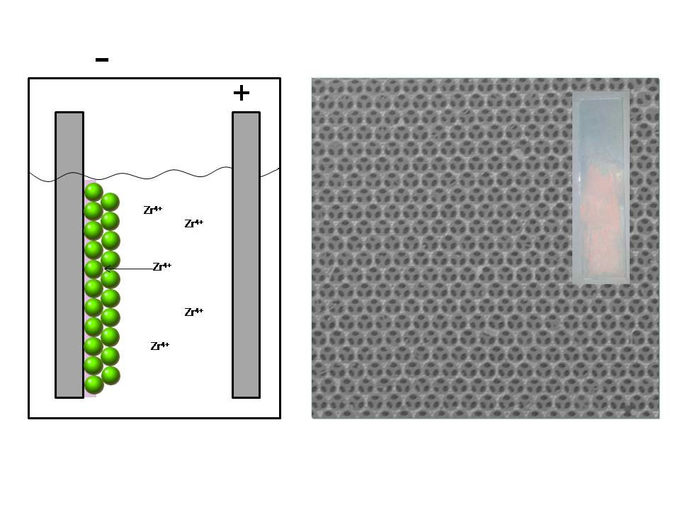
2.1. Electrodeposition of Zirconia

Identification of the scheme according to which zirconia undergoes electrodeposition is difficult in the case of complex zirconium species that exist in aqueous solutions. However, the process can be safely simplified by two reactions that include:
2H2O + 2e → H2 + 2OH
Zr4+ + 4OH + xH2O → Zr(OH)4·xH2O↓
As indicated in the above reaction equations, bubbles were observed on the cathodic substrate without the use of a colloidal crystals template when electrodeposition was carried out in a ZrOCl2 solution. Thus, the use of the substrate in combination with the colloidal crystals template for electrodeposition would cause entrapment of the bubbles in the template, which would be detrimental to the ordered structure and adhesion of the deposited membrane to the substrate. In order to restrain the generation of H2, H2O2 was introduced into the electrolyte. In the presence of H2O2, the formation of gas was no longer observed on the cathodic substrate. In this case, OH is expected to be produced via the following reaction [27]:
H2O2 + 2e → 2OH
A layer of sufficient thickness of deposited zirconia is necessary to form an obvious diffraction effect. However, the poor electrical conductivity of the deposited hydrous zirconia causes the applied voltage to increase with time. In our work, once the applied voltage reached the protective value, which was set as 5 V, the current decreased rapidly. At this stage the maximum thickness of the zirconia membrane electrodeposited from the ZrOCl2/H2O2 solution was still insufficient to form noticeable structure coloration. Hence, NaHCO3 was added to the electrolyte to adjust the pH to the isoelectric point of the zirconium ionic groups, thereby accelerating the process of electrodeposition dramatically. The result will be discussed in a subsequent section.

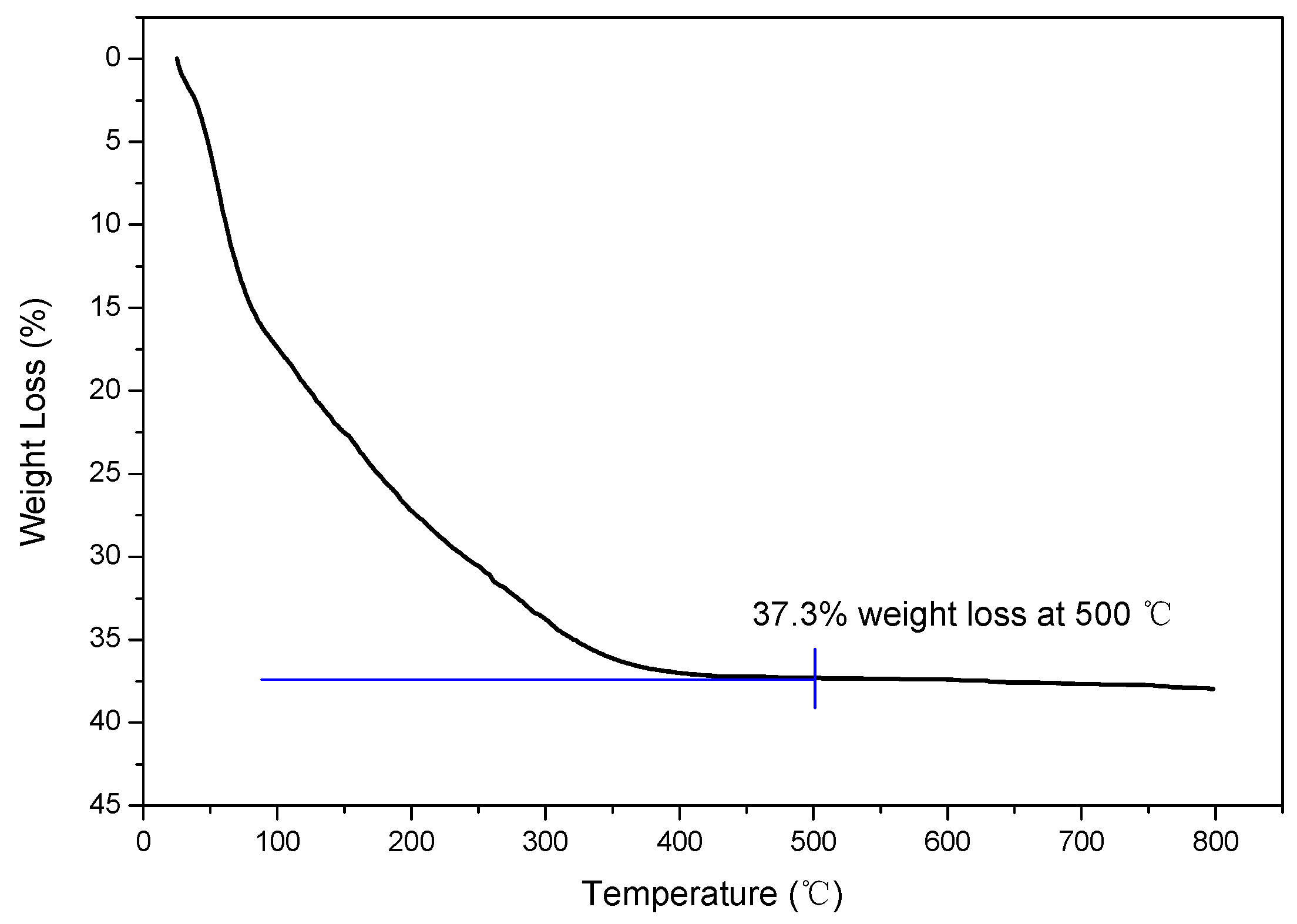
2.2. Thermogravimetric (TG) Analysis

The thermogravimetric analysis curve for the electrodeposited zirconia membrane after drying is shown in Figure 1. It can be observed that the majority of weight loss, 37.3% in total, took place before 500 °C. This result is similar to the electrodeposition of YSZ under similar conditions [28] and the observed weight loss is far lower than in the sol-gel method (65.4%) [16]. Lower weight loss is considered beneficial to preserve the structure of the colloidal crystals template and maintain the optical properties of 3DPCs. Above 500 °C up to 800 °C, the registered weight loss is only 0.6%. Furthermore, 500 °C was also found to be sufficiently high to remove the polystyrene (PS) template. Calcination at higher temperatures was found to bring about a series of destructive effects, including thermal expansion differences between the zirconia membrane and the substrate, softening of the substrate, and destruction of the indium tin oxides (ITO) layer. Therefore, heat treatments were conducted at 500°C in the subsequent experiment.

2.3. X-Ray Diffraction(XRD) Analysis

The XRD patterns of the deposited membrane before and after calcination are shown in Figure 2. The sample before calcination exhibits two broad peaks at 30° and 55°. This pattern should be regarded as being representative of amorphous zirconium hydroxide [29]. After calcination at 500 °C, the sharp peaks that appeared in the XRD pattern correspond very well with the monoclinic phase of zirconia (JCPDS card No. 37-1484), indicating that crystallization had been accomplished.

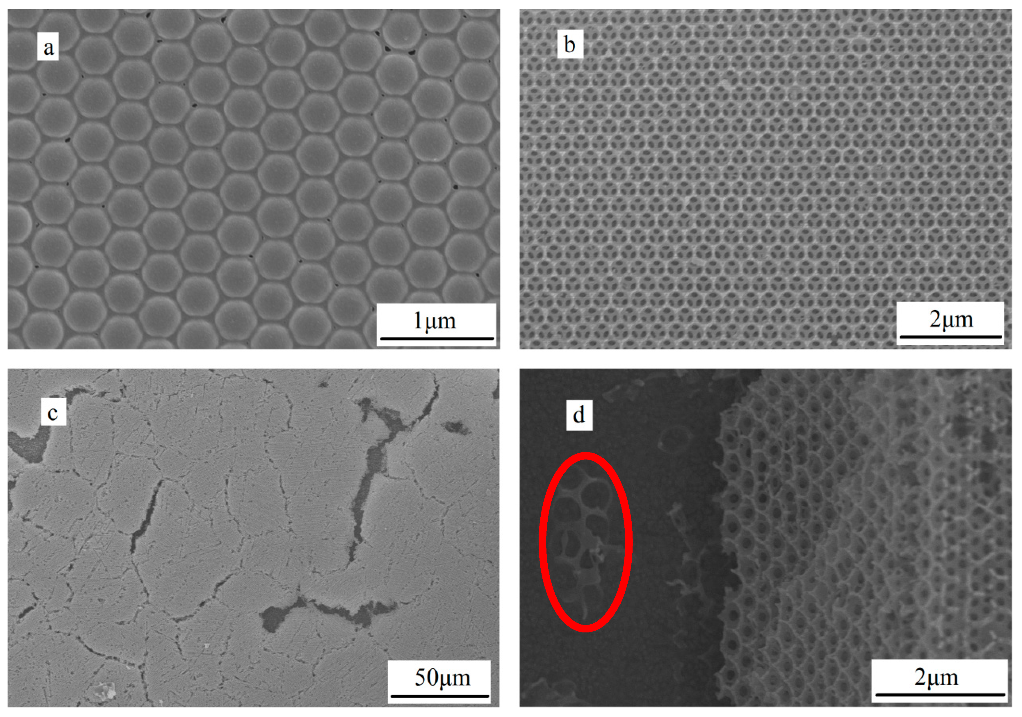
2.4. The Microstructure Analysis of Photonic Crystal Layer

The scanning electron microscopy (SEM) image in Figure 2a shows the morphology of as-deposited hydrous zirconia in the colloidal crystals template. This figure indicates that regulation of the electrodeposition conditions enables a thick hydrous zirconia membrane to be obtained. The sediment has reached the top layer of the colloidal crystals template. Although small holes can be observed on the surface of the sediment, suggesting shrinkage during the drying process, the entire membrane is maintained in a continuous and complete state. The morphologies of zirconia 3DOM after calcination at 500 °C are shown in Figure 2b–d. It can be observed from Figure 2b that the zirconia membrane is able to retain a complete inverse opal structure within a scale of about 10 μm, whereas on a larger scale, cracks resulting from shrinkage during calcination can be found, though they are at an acceptable level, as shown in Figure 2c. The shrinkage of the structure may be restricted in the two dimensionalities parallel to the substrate due to the high adhesion but still may happen vertically. The latter may lead to a blue shift of the reflective peak. The relatively limited shrinkage may be the consequence of the relatively lower water and organic substance content, as compared to the sol-gel method [16]. In addition, no severe detachment of the zirconia membrane is found. In the lower parts of the cracks, fragments of zirconia 3DOM are still tightly attached to the substrate (Figure 3d), indicating that hydrated zirconium ions were able to penetrate the colloidal crystals template easily and that the zirconia membrane grew in a bottom-up manner by starting from the substrate. This fact, along with the small amount of detachment, clearly proves the strong binding force between the zirconia membrane and the substrate. Besides, Figure 2d also shows that an inverse opal structure exceeding 10 layers was obtained by regulating the technological conditions under which electrodeposition was carried out. A certain number of structural periods would ensure the generation of multiple Bragg diffractions.

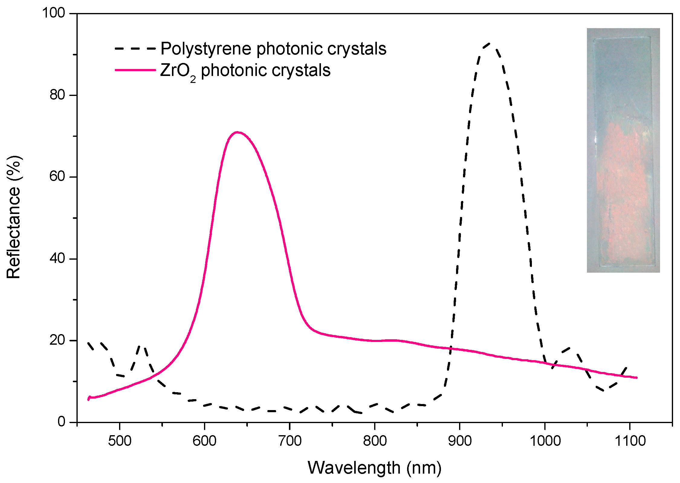
2.5. Spectral Analysis of Zirconia 3DPCs

A simple way to predict the reflective peak position (λ) of 3DPCs with an opal or inverse opal structure is to use the Bragg-Snell equation [30]:
λ = 2 2 / 3 D n e f f 2 sin 2 θ
where D is the diameter of the microspheres (391 nm for this study), and θ is the incident angle (0° for this study). Further, neff is the effective refractive index of 3DPCs and can be expressed as:
n e f f = n a 2 f + n b 2 ( 1 f )
where na and nb are the n of two different dielectric media constituting the 3DPCs and f is the volume proportion of dielectric media a. In the ideal opal structure, na, the n of PS, is 1.59 and f should be 0.746. Thus, the reflective peak of PS 3DPCs in this study should be located at 934 nm. In the case of the zirconia inverse opal structure, media a is replaced by air and the na should be 1. Media b is replaced by electrodeposited zirconia and the nb should be 2.1 if the electrodeposited zirconia has the same density as bulk zirconia. If the electrodeposited zirconia membrane precisely replicates the structure of the colloidal template, it can be calculated that the reflective peak of zirconia3DPCs should be located at 872 nm. The experimental reflective spectra of PS and zirconia 3DPCs are given in Figure 4. A reflective peak near 95% can be found for PS 3DPCs in Figure 4, whose location is in very good agreement with the predicted value, indicating the highly ordered structure of the PS 3DPCs. However, the reflective peak for zirconia 3DPCs shows a noteworthy blue shift compared with the calculated value (about 230 nm). The main reason for the blue shift may be that the actual refractive index of electrodeposited zirconia is lower than the refractive index of bulk zirconia because of its lower density derived from dehydration during calcination. However, compared with the reflective peak width of the original template, the reflective peak width of zirconia 3DPCs is expanded slightly. Therefore, the actual refractive index of electrodeposited zirconia remains higher than the refractive index of PS. The shrinkage of the structure, especially in the vertical direction, along with the volume proportion of zirconia which is lower than the ideal value, may also contribute to the blue shift. Moreover, in comparison with the reflective peak of the colloidal crystals template, the intensity of the reflective peak of zirconia 3DPCs is reduced because of the cracks (see Figure 3c), although to an acceptable extent (higher than 70%), indicating that the orderliness of the template is adequately preserved.
In summary, zirconia 3DPCs are able to maintain the ordered structure of the original template; hence, strong multiple Bragg diffractions are generated, thereby apparently resulting in a salmon-colored structure (see Figure 4 insert).

3. Materials and Methods

All reagents except the water used were purchased from Sigma-Aldrich without further purification. High-purity water with a resistivity of 18.2 MΩ·cm at 25 °C was prepared by using a water purification system (CSR-1-30T). Monodisperse polystyrene (PS) microspheres with an average diameter of 391 nm were synthesized by an emulsifier-free emulsion polymerization technique [31]. The polydispersity index (PDI) of diameter was 1.04.
The cathodic electrodeposition of zirconia was performed with a CHI-660D electrochemical workstation. Indium-doped tin oxide glass slides (ITO, 1×5 cm, ~9 Ω) were used as cathodic substrates. In the fabrication of inverse opal zirconia, PS colloidal crystal templates were grown on the ITO in advance by vertical deposition [9,16]. A rectangular Pt (1×5 cm) electrode was used as counter electrode.
First, an aqueous solution containing 0.2 M ZrOCl2 and 0.24 M H2O2 was prepared, to which an aqueous solution of 0.1 M NaHCO3 was added drop by drop until a small amount of sedimentation was generated. The precipitationwould dissolve after vibration. Then the solution was diluted untilthe concentration of ZrOCl2 was 0.1 M. Galvanostatic electrodeposition was carried out with a current density of 1 mA/cm2 in an ice/water bath. The as-deposited films were dried for 24 h at 80 °C, followed by calcination for 1 h at 500°C to remove the PS template.
SEM images were obtained using a Hitachi SU 8010 microscope operated at 15 kV. The average diameter of the PS microspheres was calculated from more than 100 microspheres. PDI = Dm/Dn−1, where Dm and Dn were the weight-average and number-average diameters, respectively [32]. The normal-incident reflectance spectra of 3DPCswere obtained by using an Ocean Optics Maya 2000-Pro instrument equipped with a reflection probe. A specular reflectance standard (PN A338-MS-1)with a reflectance of 85%–90% was used as measured reference. The thermogravimetric analysis was performed using an STA8000 device at a scan rate of 10 °C/min with a 25 mL/min flow of nitrogen of 99.99% purity. The crystalline structures of the membrane were analyzed by using a D/Max-rB X-ray diffractometer (Cu Kα radiation) at a scan rate of 5°/min.

4. Conclusions

In this study, zirconia 3DPCs with a continuous ordered structure in a large area were obtained by an electrodeposition method. PS colloidal crystals on ITO glass were used as sacrificial templates and an aqueous solution of ZrOCl2 was used as an electrolyte, to which H2O2 was added to restrain the generationof hydrogen and to which NaHCO3 solution was added to regulate the pH to increase the thickness of the deposited membrane. Calcination at 500 °C was employed to remove the template and water. The zirconia 3DPCs fabricated by electrodeposition had relatively high density and strong adhesion, with very good preservation of the orderliness of the colloidal crystals template, resulting in an obvious reflective peak and structural color. The high quality of the electrodeposited zirconia 3DPCs may be attributable to the following: the low water content in electrodeposited hydrous zirconia with a consequent low weight loss during calcination, together with a bottom-up deposition mode that ensures bonding between the deposited member and the substrate and a comparatively low degree of detachment.
Most of the above conclusions may also be valid for multiple other metallic oxides. Therefore, this study has provided a new approach to prepare high-quality inverse opal 3DPCs with metallic oxides.

Acknowledgments

We thank the National Natural Science Foundation of China (No.51572058, 91216123, 51174063, 51502057), the Heilongjiang Postdoctoral Fund (No. LBH-Z15078), the Aerospace support fund (NO. JZ20150048), the Natural Science Foundation of Heilongjiang Province (E201436), the International Science & Technology Cooperation Program of China (2013DFR10630, 2015DFE52770) and the Specialized Research Fund for the Doctoral Program of Higher Education (SRFDP 20132302110031).

Author Contributions

Jiupeng Zhao and Yao Li conceived the research plan, Yunyong Sun performed the experiments, Hongbo Xu analyzed the data and Lei Pan wrote the paper.

Conflicts of Interest

The authors declare no conflict of interest.

References

  1. Yablonovitch, E. Inhibited spontaneous emission in solid-state physics and electronics. Phys. Rev. Lett. 1987, 58, 2059–2062. [Google Scholar] [CrossRef] [PubMed]
  2. John, S. Strong localization of photons in certain disordered dielectric superlattices. Phys. Rev. Lett. 1987, 58, 2486–2489. [Google Scholar] [CrossRef] [PubMed]
  3. Mekis, A.; Chen, J.C.; Kurland, I.; Fan, S.H.; Villeneuve, P.R.; Joannopoulos, J.D. High transmission through sharp bends in photonic crystal waveguides. Phys. Rev. Lett. 1996, 77, 3787–3790. [Google Scholar] [CrossRef] [PubMed]
  4. Lin, S.Y.; Chow, E.; Hietala, V.; Villeneuve, P.R.; Joannopoulos, J.D. Experimental demonstration of guiding and bending of electromagnetic waves in a photonic crystal. Science 1998, 282, 274–276. [Google Scholar] [CrossRef] [PubMed]
  5. Yablonovitch, E. Photonic band-gap structures. J. Opt. Soc. Am. B: Opt. Phys. 1993, 10, 283–295. [Google Scholar] [CrossRef]
  6. Lai, C.-F.; Wang, Y.-C. Colloidal photonic crystals containing silver nanoparticles with tunable structural colors. Crystals 2016, 6, 61. [Google Scholar] [CrossRef]
  7. Blanco, A.; Chomski, E.; Grabtchak, S.; Ibisate, M.; John, S.; Leonard, S.W.; Lopez, C.; Meseguer, F.; Miguez, H.; Mondia, J.P.; et al. Large-scale synthesis of a silicon photonic crystal with a complete three-dimensional bandgap near 1.5 micrometres. Nature 2000, 405, 437–440. [Google Scholar] [PubMed]
  8. Meng, X.; Al-Salman, R.; Zhao, J.; Borissenko, N.; Li, Y.; Endres, F. Electrodeposition of 3D ordered macroporous germanium from ionic liquids: A feasible method to make photonic crystals with a high dielectric constant. Angew. Chem. Int. Ed. 2009, 48, 2703–2707. [Google Scholar] [CrossRef] [PubMed]
  9. Li, Z.; Yang, L.; Ge, D.; Ding, Y.; Pan, L.; Zhao, J.; Li, Y. Magnetron sputtering sic films on nickel photonic crystals with high emissivity for high temperature applications. Appl. Surf. Sci. 2012, 259, 811–815. [Google Scholar] [CrossRef]
  10. Xin, W.; Zhao, J.; Ding, Y.; Li, Y. Fabrication of three-dimensionally ordered macroporous Ta2O5 films through aqueous organic gel process. Appl. Surf. Sci. 2011, 257, 10725–10728. [Google Scholar]
  11. Huang, K.M.; Ho, C.L.; Chang, H.J.; Wu, M.C. Fabrication of inverted zinc oxide photonic crystal using sol-gel solution by spin coating method. Nanoscale Res. Lett. 2013, 8. [Google Scholar] [CrossRef] [PubMed]
  12. Tong, Z.; Hao, J.; Zhang, K.; Zhao, J.; Su, B.-L.; Li, Y. Improved electrochromic performance and lithium diffusion coefficient in three-dimensionally ordered macroporous V2O5 films. J. Mater. Chem. C 2014, 2, 3651–3658. [Google Scholar] [CrossRef]
  13. Kapitonov, A.M.; Gaponenko, N.V.; Bogomolov, V.N.; Prokofiev, A.V.; Samoilovich, S.M.; Gaponenko, S.V. SiO2/TiO2 submicron 3D lattice: A new step towards visible-range photonic crystals. Nanoscale Res. Lett. 1997, 54–57. [Google Scholar] [CrossRef]
  14. Zakhidov, A.A.; Baughman, R.H.; Iqbal, Z.; Cui, C.X.; Khayrullin, I.; Dantas, S.O.; Marti, I.; Ralchenko, V.G. Carbon structures with three-dimensional periodicity at optical wavelengths. Science 1998, 282, 897–901. [Google Scholar] [CrossRef] [PubMed]
  15. Ge, D.; Yang, L.; Tong, Z.; Ding, Y.; Xin, W.; Zhao, J.; Li, Y. Ion diffusion and optical switching performance of 3D ordered nanostructured polyaniline films for advanced electrochemical/electrochromic devices. Electrochim. Acta 2013, 104, 191–197. [Google Scholar] [CrossRef]
  16. Zhao, J.P.; Li, Y.; Xin, W.H.; Li, X. Preparation and characterization of three-dimensionally ordered macroporous yttria-stabilized zirconia by aqueous organic gel route. J. Solid State Chem. 2008, 181, 239–244. [Google Scholar] [CrossRef]
  17. Lashtabeg, A.; Drennan, J.; Knibbe, R.; Bradley, J.L.; Lu, G.Q. Synthesis and characterisation of macroporous yttria stabilised zirconia (YSZ) using polystyrene spheres as templates. Microporous Mesoporous Mater. 2009, 117, 395–401. [Google Scholar] [CrossRef]
  18. Lashtabeg, A.; Bradley, J.L.; Vives, G.; Drennan, J. The effects of templating synthesis procedures on the microstructure of yttria stabilised zirconia (YSZ) and NiO/YSZ templated thin films. Ceram. Int. 2010, 36, 653–659. [Google Scholar] [CrossRef]
  19. Xiaolong, X.; Hui, Z.; Shengnan, L.; Fan, L.; Jinxiu, W. Preparation of three-dimensional ordered macroporous zirconia and characteristics of its pore walls. J. Chin. Ceram. Soc. 2013, 36, 705–709. [Google Scholar]
  20. Shen, Y.; Wu, Q.Z.; Li, Y.G. Three dimensional ordered macroporous ZrO2 prepared by directly calcining ZrOCl2. Acta. Phys. Chim. Sin. 2006, 22, 1121–1125. [Google Scholar]
  21. Davis, M.; Ramirez, D.A.; Hope-Weeks, L.J. Formation of three-dimensional ordered hierarchically porous metal oxides via a hybridized epoxide assisted/colloidal crystal templating approach. ACS Appl. Mater. Interfaces 2013, 5, 7786–7792. [Google Scholar] [CrossRef] [PubMed]
  22. Zhang, N.; Li, J.; Li, W.; Ni, D.; Sun, K. High performance three-dimensionally ordered macroporous composite cathodes for intermediate temperature solid oxide fuel cells. Rsc Adv. 2012, 2, 802–804. [Google Scholar] [CrossRef]
  23. Liang, B.; Suzuki, T.; Hamamoto, K.; Yamaguchi, T.; Sumi, H.; Fujishiro, Y.; Ingram, B.J.; Carter, J.D. A reduced temperature solid oxide fuel cell with three-dimensionally ordered macroporous cathode. J. Power Sources 2012, 212, 86–92. [Google Scholar] [CrossRef]
  24. Zhang, X.; Su, H.; Yang, X. Catalytic performance of a three-dimensionally ordered macroporous Co/ZrO2 catalyst in fischer-tropsch synthesis. J. Mol. Catal. A Chem. 2012, 360, 16–25. [Google Scholar] [CrossRef]
  25. Misawa, H.; Nishijima, Y.; Ueno, K.; Juodkazis, S.; Mizeikis, V.; Maeda, M.; Minaki, M. Tunable single-mode photonic lasing from zirconia inverse opal photonic crystals. Opt. Express 2008, 16, 13676–13684. [Google Scholar] [CrossRef] [PubMed]
  26. Schroden, R.C.; Al-Daous, M.; Blanford, C.F.; Stein, A. Optical properties of inverse opal photonic crystals. Chem. Mater. 2002, 14, 3305–3315. [Google Scholar] [CrossRef]
  27. Zhitomirsky, I. Cathodic electrodeposition of ceramic and organoceramic materials. Fundamental aspects. Adv. Colloid Interface Sci. 2002, 97, 279–317. [Google Scholar] [CrossRef]
  28. Zhigang, X.; Tameru, S.; Sankar, J. Synthesis of yttria stabilized zirconia thin films by electrolytic deposition. Ceram. Eng. Sci. Proc. 2004, 25, 339–344. [Google Scholar]
  29. Aghazadeh, M. Cathodic electrodeposition of ZrO2: Impact of current density on the crystal structure, composition and morphology. J. Electrochem. Soc. 2012, 159, E53–E58. [Google Scholar] [CrossRef]
  30. Allard, M.; Sargent, E.H.; Kumacheva, E.; Kalinina, O. Characterization of internal order of colloidal crystals by optical diffraction. Opt. Quant. Electron. 2002, 34, 27–36. [Google Scholar] [CrossRef]
  31. Wang, H.; Zhang, S.; Wang, M.Z.; Ge, X.W. Preparation of monodisperse polystyrene particles from emulsifier-free miniemulsion polymerization. Chem. Lett. 2008, 37, 1158–1159. [Google Scholar] [CrossRef]
  32. Pan, L.; Wang, Y.; Xu, H.; Ding, Y.; Li, Y.; Zhao, J. Synthesis of silica particles with precisely tailored diameter. Chin. J. Chem.Phys. 2014, 27, 563–567. [Google Scholar] [CrossRef]
Figure 1. Thermogravimetric (TG) curves of the hydrous ZrO2 membrane.
Crystals 06 00076 g001
Figure 2. X-ray diffraction (XRD) patterns for deposited membrane before and after calcination.
Crystals 06 00076 g002
Figure 3. Scanning electron microscopy (SEM) images for (a) Polystyrene/hydrous ZrO2 3DPCs; (bd) ZrO2 3DPCs.
Crystals 06 00076 g003
Figure 4. Reflectance spectra for polystyrene and ZrO2 3DPCs and the visual appearance of ZrO2 3DPCs (insert).
Crystals 06 00076 g004

