Advanced Design and Synthesis of Composite Photocatalysts for the Remediation of Wastewater: A Review


Department of Chemistry and Chemical Engineering, Inha University, 100 Inharo, Incheon 22212, Korea
*
Author to whom correspondence should be addressed.
Catalysts 2019, 9(2), 122; https://doi.org/10.3390/catal9020122
Submission received: 29 December 2018
/
Revised: 25 January 2019
/
Accepted: 28 January 2019
/
Published: 30 January 2019
(This article belongs to the Special Issue New Trends in Photo(Electro)catalysis: From Wastewater Treatment to Energy Production)
Abstract
:Serious water pollution and the exhausting of fossil resources have become worldwide urgent issues yet to be solved. Solar energy driving photocatalysis processes based on semiconductor catalysts is considered to be the most promising technique for the remediation of wastewater. However, the relatively low photocatalytic efficiency remains a critical limitation for the practical use of the photocatalysts. To solve this problem, numerous strategies have been developed for the preparation of advanced photocatalysts. Particularly, incorporating a semiconductor with various functional components from atoms to individual semiconductors or metals to form a composite catalyst have become a facile approach for the design of high-efficiency catalysts. Herein, the recent progress in the development of novel photocatalysts for wastewater treatment via various methods in the sight of composite techniques are systematically discussed. Moreover, a brief summary of the current challenges and an outlook for the development of composite photocatalysts in the area of wastewater treatment are provided.
1. Introduction
In the past several decades, with the booming of industry, the ever-increasing consumption of natural resources, especially fresh water and fossil resources, have caused alarming damage to the environment and seriously threaten the sustainability of human society [1,2,3]. As a worldwide concern, freshwater pollution drives people to seek for an effective approach to repair the polluted water environment. In general, the contaminants in water are mainly derived from the sewage effluent of industries (e.g., textile industry, paper industry, the pharmaceutical industry, etc.), and domestic contaminants (e.g., pharmaceuticals, pesticide, detergent, etc.) [4]. Until now, numerous contaminants have been detected and are classified as inorganic ions, organic chemicals, and pathogens; most of those contaminants are toxic to organisms [4,5,6,7]. Up to now, a variety of strategies including chemical or physical coagulation [8], sedimentation [9], adsorption [10], membrane filtration [11], and biological degradation method [12] have been invented to treat wastewater. However, due to the complex compositions and different physico-chemical properties of the contaminants, there are still several limitations of these traditional techniques, such as the low efficiency, high energy consumption, and the risk of secondary pollution [13,14,15]. Consequently, a promoted technique with high efficiency, low energy consumption, and being environmentally friendly is highly desired for the remediation of wastewater.
Nowadays, the advanced oxidation processes (AOPs) have been extensively explored to remove the non-biodegradable and highly stable compounds in water [16,17]. In fact, the AOPs are chemical processes that can generate highly reactive hydroxyl radicals (·OH) in situ. The ·OH in water exhibits an extremely strong oxidizing property with a high oxidation potential of 2.80 V/SHE (·OH/H2O), such that it can non-selectively oxidize the contaminants and finally convert them to CO2, H2O, or small inorganic ions in a short time [17,18]. In most cases, the ·OH could be produced with the presence of one or more primary oxidants, and/or energy sources or catalysts. Therefore, the typical AOPs could be classified as Fenton reactions, the electrochemical advanced oxidation processes, and the heterogeneous photocatalysis [17]. Compared with the traditional water remediation techniques, the AOPs exhibit many advantages, which include: (1) the contaminants are directly destroyed or reduced in the water body, rather than simply coagulated or filtrated from the water, thus the secondary pollution could be avoided; (2) the AOPs are suitable for a wide range of contaminants including some inorganics and pathogens because of their robust non-selectively oxidizability; and (3) no hazardous byproducts will be generated due to the final reduction products of the AOPs being just CO2, H2O, or small inorganic ions. With the abovementioned merits, the AOPs have attracted significant attention from both scientific research and industrial processing [19].
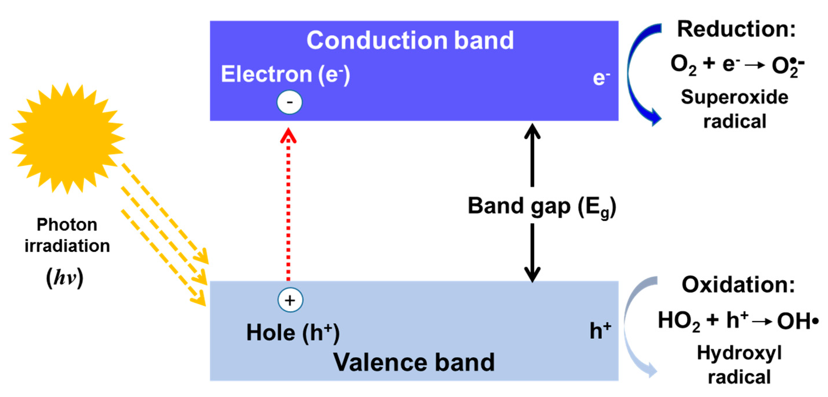
Solar energy is a green, costless, and inexhaustible energy resource. Effective utilization of solar energy is of vital importance for enhancing the sustainability of industry, reducing pollution, and retarding global warming. Consequently, solar energy has been widely used in a range of applications, such as solar heating, photovoltaics, solar thermal energy, solar architecture, artificial photosynthesis, photocatalysis, etc. [20] Among which, photocatalysis is one of the most effective strategies for the AOPs, which just rely on the light radiation on the photocatalysts to drive the oxidization reaction at the ambient condition, and during the whole reaction process, no additional energy is needed and no toxic byproduct will be generated; therefore, it is a green chemical technique [21,22]. Actually, the core of photocatalytic AOPs are photocatalysts; semiconductors as the most employed heterogeneous photocatalysis for the AOPs have attained considerable development since Fujishima et al. [23] carried out the first photo-catalyzed AOP based on the titanium-oxide (TiO2) in 1972. Up to now, a myriad of photocatalytic AOPs have been designed for water treatment based on various semiconductors. In general, semiconductors are light-sensitive because of their unique electronic structure with a filled valence band (VB) and an empty conduction band (CB) [18,21]. Figure 1 and Equations (1)–(6) demonstrate the basic reaction process of a semiconductor to generate the photocatalytic radicals, which could be decomposed in the following steps: (i) photons with a certain energy are absorbed by the semiconductor; (ii) the absorbed photons with energy greater than the band gap energy (Eb) of semiconductors lead to the formation of electrons in the CB and corresponding holes in the VB; and (iii) the generated electron–hole pairs will migrate to the surface of semiconductors for redox reactions, and fast recombination in nanoseconds will happen at the same time (it should be mentioned that this process is negative for the AOPs, which shall be suppressed [21,22]).
Excitation: Photon (hv) + Semiconductor → e−CB + h+VB
Recombination: e− + h+ → energy
Oxidation of H2O: H2O + h+VB → •OH + H+
Reduction of adsorbed O2: O2 + e− → O2•−
Reaction with H+: O2•− + H+ → •OOH
Electrochemical reduction: •OOH + •OOH → H2O2 + O2
However, it remains a significant challenge to fabricate a high-efficiency visible light photocatalyst solely based on an individual semiconductor photocatalyst. For example, the TiO2, as the most used photocatalyst, possesses various advantages with excellent chemical stability, large surface area, non-toxicity, and low cost [24]; however, its wide energy band gap (3.0–3.2 eV) means it can only be excited by the UV light (λ < 400 nm), such that less than 5% of the irradiated solar energy can be effectively used [25]. Moreover, the fast recombination speed of electron–hole pairs seriously limits the further improvement of its photocatalytic activity [18,22]. On the other hand, although the recently developed visible light response semiconductors have a lower energy band gap (<3 eV), such as BiOX (X = I or Br) [26], they still suffer from serious photo-corrosion problems in aqueous media via redox reactions and the fast recombination of electron–hole pairs during the reaction process. Therefore, it is highly urgent to find an effect strategy to further improve the performance of semiconductor photocatalysts.
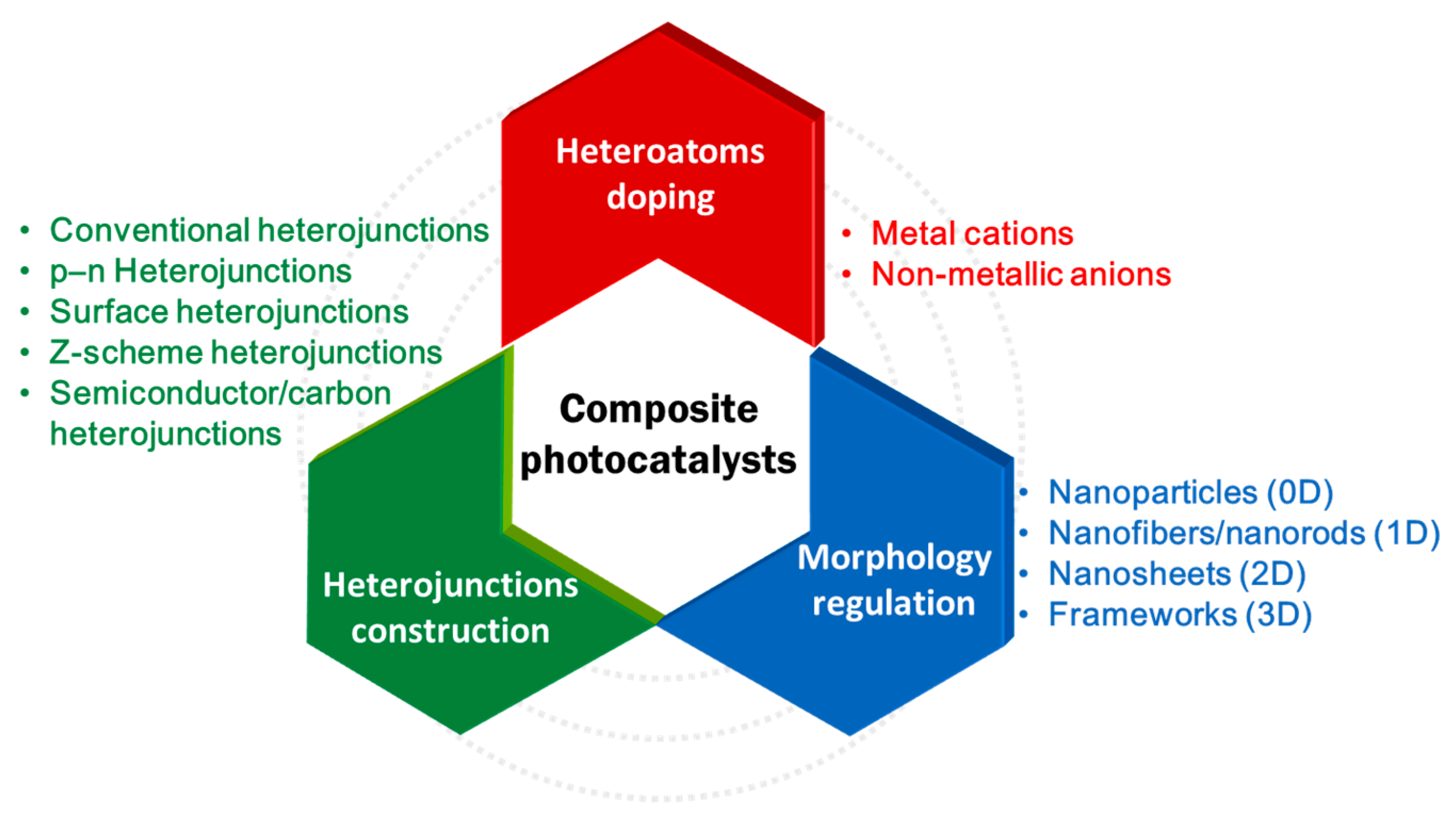
From ancient times, people have recognized that the incorporation of two or more constituent materials could obtain various composite materials with intriguing properties superior to the individual components. Nowadays, a myriad of functional composite materials have been developed for different applications [27,28]. Actually, the enhanced performance of a composite material is mainly attributed to the synergistic effect of its individual constituent materials; meanwhile, this principle is also appropriate to the design of semiconductor photocatalysts. Up to now, there have been numerous pioneering studies reporting the design and fabrication of composite semiconductor photocatalysts via various methods, such as doping heteroatoms or constructing heterojunctions via directly compositing with individual semiconductors or carbonaceous nanomaterials, among others. Therefore, as shown in Scheme 1, in this review, we aim to provide a systematic appraisal of the recent development in the design and fabrication of various composite photocatalysts for the application of wastewater treatment. Meanwhile, some representative photocatalysts with composite structures and morphologies from the atomic scale to macroscopic scale are reviewed. Finally, the current developing status, challenges, and evolution trend of the composite semiconductor photocatalysts for wastewater remediation are briefly proposed.
2. Principle of the Semiconductor Photocatalysts for Wastewater Remediation
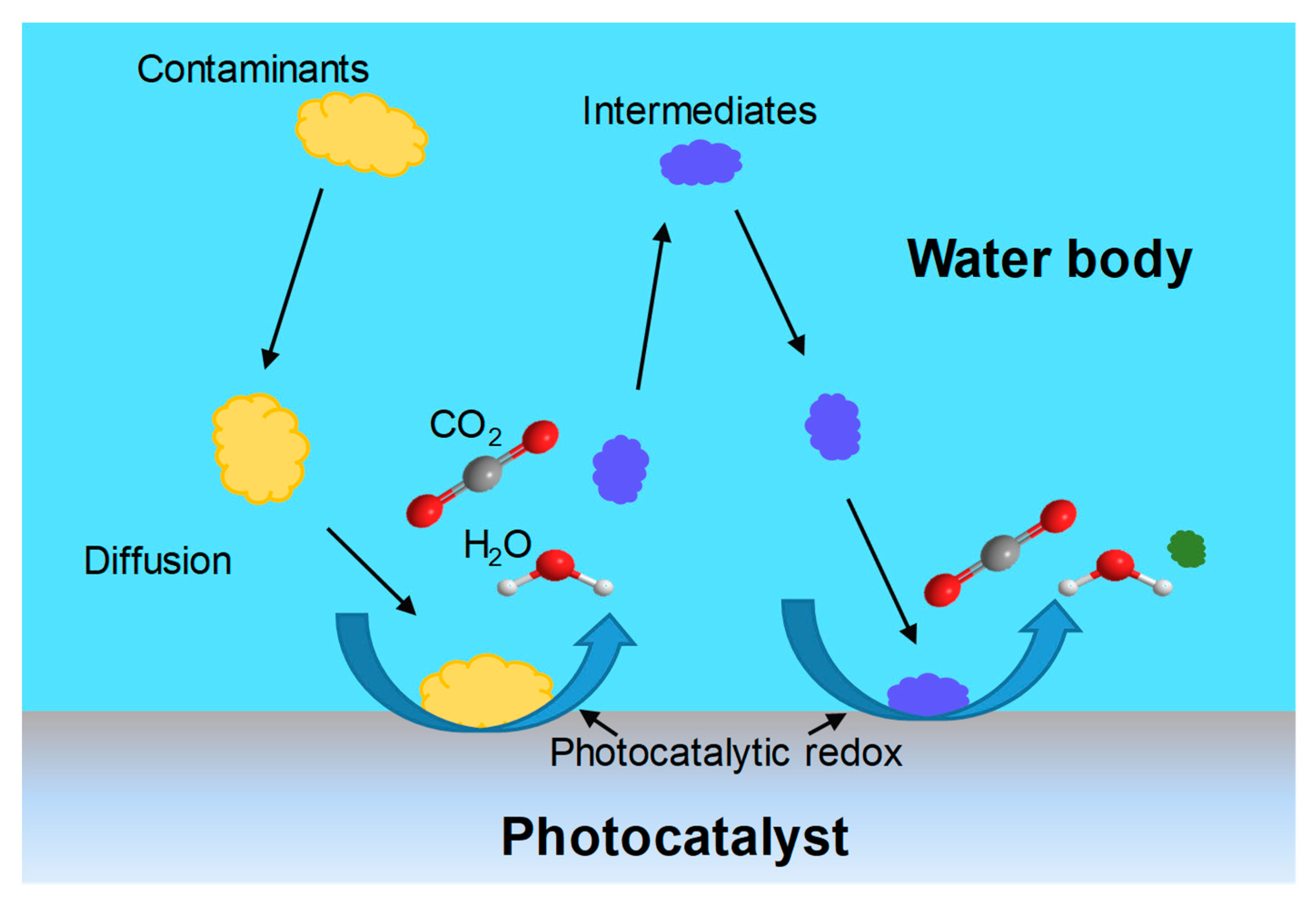
As mentioned above, the trace contaminants (e.g., phenol, chlorophenol, oxalic acid) derived from the dyeing industry, petrochemical industry, and the agricultural chemicals are quite difficult to remove from the water due to the low concentration and complex compositions [4]. A photocatalytic degradation method is considered as the most promising strategy to deal with this problem. According to the previous studies [18,29,30], as shown in Figure 2, the basic mechanism of the photocatalytic degradation process of a contaminant could be characterized as the following steps: (i) the target contaminants transfer from the water body to the surface of the photocatalysts, in which the migration rate of corresponding contaminants may be influenced by the morphology and surface properties of the catalysts (e.g., surface area, porosity, and surface charges); (ii) the contaminants are adsorbed on the surface of catalysts with photon excited reaction sites, therefore a high surface area of the catalysts can provide more active sites for the reaction; (iii) the redox reactions of the photon activated sites with the adsorbed contaminants and the degraded intermediates are produced, which are finally degraded to CO2 and H2O; (iv) part of the generated intermediates and the resultant mineralization products (CO2 and H2O) desorb from the surface of catalysts to expose the active sites for the subsequent reactions; and (v) the desorbed intermediates transfer from the interface of catalysts and water to the bulk liquid, and part of the intermediates will repeat the procedure i–v until they are completely degraded to CO2 and H2O. Based on the abovementioned principles of the semiconductor photocatalysts for water contaminants degradation, five main criteria for the design of an effective photocatalyst could be proposed as follow: (1) a semiconductor with a lower Eg is preferred so that the electron–hole pair could be excited easier; (2) the photon absorption capacity of the catalysts shall be as high as possible to generate more electron–hole pairs; (3) the recombination process of electron–hole pairs must be prevented as much as possible to enhance the quantum efficiency of the photo-generated electron–hole pairs; (4) the surface area of the catalysts shall be large to provide more reaction sites; and (5) the chemical and physical structures of photocatalysts must be stable and be beneficial for the mass transfer in water. To meet the abovementioned requirements, a variety of strategies have been developed for the design, some of the most-used strategies will be summarized in this review.
3. Heteroatoms Doping
Recently, the strategy of introducing heteroatoms into the lattice of corresponding semiconductors has been widely employed to regulate the band gap of the semiconductor photocatalysts so as to improve their absorption capacity for visible lights, which takes up almost 45% in the solar light spectrum [31]. In general, the most commonly used dopants in semiconductors (e.g., TiO2) could be classified as the metal cations and the non-metallic elements [32,33].
3.1. Metal Cations Doping
The most-used metal cation dopants for semiconductors mainly involve transition metal ions, such as Fe3+, Co3+, Mo5+, Ru3+, Ag+, Cu2+, Rb+, Cr3+, V4+, etc. [32,34,35,36,37]. In most cases, the redox energy states of those employed metal cations lie within the band gap states of corresponding semiconductors (e.g., TiO2); therefore, the introduction of those metal ions will result in an intraband state near the CB or VB edge of a semiconductor. Consequently, the red shift in band gap absorption of a metal-cation-doped semiconductor is mainly contributed by the charge migration between the d electrons of the doped cations and the CB (or VB) of the corresponding semiconductors. In addition, the doped metal cations could act as an electron–hole trap, regulating the charge carrier equilibrium concentration [38,39,40]. Although some transition metal cations could provide new energy levels as electron donors or acceptors, and virtually improved the visible light absorption capacity of corresponding semiconductors, this approach is also known to suffer from many disadvantages, such as bad thermal stability, significant increase in the carrier-recombination centers, and the high cost for an expensive facility, which are critical limitations for the generalization of this strategy.
3.2. Non-Metallic Anions Doping
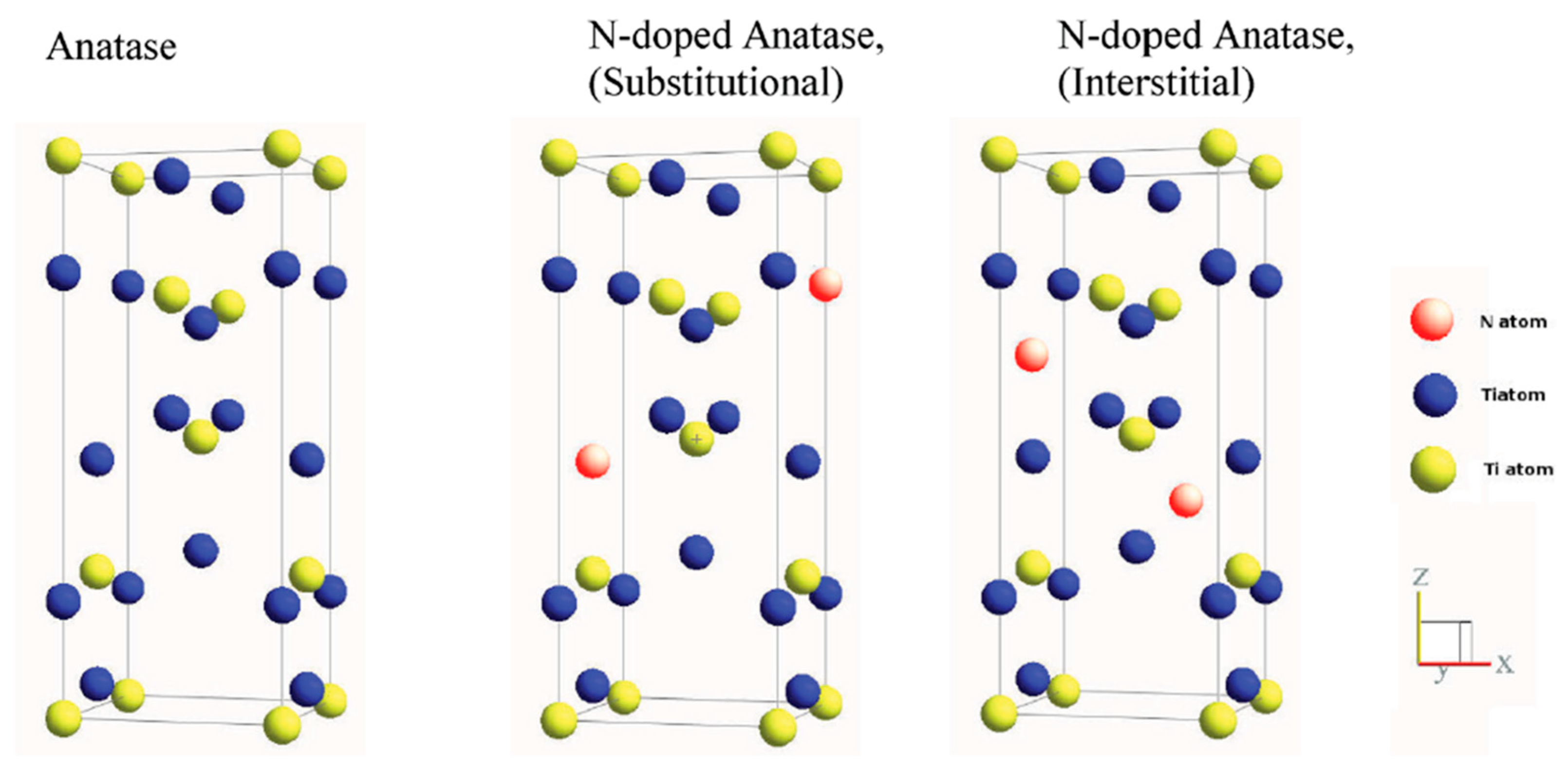
Alternatively, doping the semiconductors with appropriate non-metallic anions has been proven to be a facile way to regulate the intrinsic electronic structure of semiconductors and could construct various heteroatomic surface structures such that the resultant non-metallic-anion-doped semiconductors exhibit improved photocatalytic performances under solar light irradiation [33,41]. In general, the chemical states and locations are key factors for the regulation of the electronic state of the dopant and the corresponding heteroatomic surface structures of the composite semiconductor catalysts. According to a previous study [18], three requirements needed to be satisfied for the doping of a semiconductor: (i) the doping process should construct states in the band gap of corresponding semiconductors with an enhanced visible light absorption capacity, (ii) the CB minimum including the doped states should be equal to that of the semiconductor’s or higher than that of the H2/H2O level such that the photoreduction can be conducted, and (iii) the states in the gap should sufficiently overlap with the band states of semiconductors to ensure that the photoexcited carriers could migrate to the surface of catalysts within their lifetime. Based on the abovementioned principles, various elements, including C, N, F, P, and S, were employed to substitute for the O in TiO2 [42], and the results showed that N was the most effective dopant for the improvement of visible-light photocatalysis of TiO2 because the p states of N can narrow the band gap of N-doped TiO2 via mixing with the O 2p states [43]. Moreover, owing to the comparable atomic size with oxygen, small ionization energy, and high stability, the nitrogen has been one of the most promising elements for promoting the photocatalysis performance of the semiconductors. In general, the doped N in the TiO2 could be classified as the substitutional type and interstitial type (Figure 3), the substitutional type N-doped TiO2 is attributed to the oxygen replacement, while the interstitial type is attributed to the additional N element in the lattice of TiO2 [41]. Up to now, the N-doping of semiconductors can be realized via several strategies, and the most-used techniques with certain industrial application prospects could be mentioned as the magnetron sputtering, ion implantation, chemical vapor deposition, atomic layer deposition, and sol-gel and combustion method, which will be discussed as follows.
3.2.1. Magnetron Sputtering Method
The magnetron sputtering method is widely used for the preparation of various hybrid semiconductors. For example, Kitano et al. [44] fabricated nitrogen-substituted TiO2 thin films by using a radio frequency magnetron sputtering (RF-MS) method. The N2/Ar gas mixtures with different concentration of N2 was used as the sputtering gas. They systematically investigated the influence of nitrogen content on the properties of the obtained N-TiO2 thin films via regulating the concentration of N2 in the sputtering gases. Meanwhile, they proved that the extent of substitution of oxygen positions with N in the lattice of TiO2 as well as the surface morphologies of TiO2 could be controlled well. As a result, the visible light absorption capacity of the obtained N-TiO2 was obviously enhanced with bands up to 550 nm, and it was found that the band red shift extent was closely related to the content of the substituted N element in the TiO2 lattice. Moreover, they found that the as-prepared N-TiO2 photocatalyst exhibited an optimized photocatalysis reactivity with the N content of 6%. This result was because of the excessive substituted N, which causes the formation of undesirable Ti3+ species and acts as the recombination centers to decrease the photocatalytic activity [44]. Apart from the TiO2, some other N-doped semiconductors could also be prepared based on the RF-MS method. Recently, Salah et al. [45] fabricated a series of N-doped ZnO nanoparticles films by employing the RF-MS method. As shown in Figure 4, the obtained N-doped ZnO films exhibited an improved response to the visible light, and possessed significantly enhanced degradation/mineralization performance for 2-chlorophenol (2-CP), 4-chlorophenol (4-CP), and 2,4-dichlorophenoxyaceticacid (2,4-D) solely under the drive of natural sunlight.
3.2.2. Ion Implantation Method
The ion implantation method as a typical materials engineering strategy that can effectively regulate the physical, chemical, and electronic properties of semiconductors, and the operation process does not involve any other elements except the selected element, which ensures the purity of the dopant [46]. Moreover, owing to the controllable parameters of ion beam implantation, such as ion element, ion energy, ion density, uniformity of ion beam, and the doping efficiency, ion beam implantation is a powerful approach for the heteroatom doping of semiconductors. For example, Tang et al. [47] fabricated an N-doped TiO2 layer with macrospores on a titanium substrate by using the plasma-based ion implantation method. The fabrication process involves four steps: (i) a helium plasma was employed to generate He bubbles in the substrate, (ii) an oxygen plasma treatment and a followed annealing in air were used to obtain rutile and anatase phases of TiO2, (iii) an Ar ion sputtering method was used to exposure the He bubbles on the surface; and (iv) the pre-treated samples were doped by nitrogen though the nitrogen beam ion implantation method. Moreover, co-doping of two or more non-metallic anions into a semiconductor photocatalyst (e.g., TiO2) could also be realized using the ion implantation method. For example, Song et al. [48] prepared C/N-implanted single-crystalline rutile TiO2 nanowire arrays by using carbon and nitrogen ions beam to treat the as-prepared TiO2 nanowire arrays. After an annealing treatment, the obtained C/N-doped TiO2 nanowire arrays exhibited a superior visible light response activity, which was attributed to the synergistic effect between the doped C and N atoms. Their work proved that the co-doped C and N in the lattice of TiO2 not only greatly improves the visible light absorption capability, but also enhances the separating and transferring property of photo-generated electron–hole pairs (Figure 5).
3.2.3. Chemical Vapor Deposition Method
Chemical vapor deposition (CVD) is a low-cost and scalable technique, which can directly grow a solid-phase material from a gas phase containing specific precursors. The CVD method has been widely used for the fabrication of semiconductors and the corresponding composite of oxides, sulfides, nitrides, and other mixed anion materials [49]. For example, Lee et al. [50] prepared TiO2 composite materials doped by C (TiOC) and N (TiON) with the titanium tetraisopropoxide (TTIP), oxygen, and NH3 as the precursors via combing the CVD method with a fluidized bed. The results demonstrated that the visible light photocatalysis performance of the composite TiO2 (e.g., TiON) was significantly improved compared to the commercial TiO2 catalyst (P25, Degussa). Similarly, Kafizas et al. [51] employed a combinatorial atmospheric pressure chemical vapor deposition (cAPCVD) method to prepare an anatase TiO2 film with a gradating N content. The obtained TiO2 film exhibited a gradating substitutional (Ns) and interstitial (Ni) nitrogen concentration, and the transition process from predominantly Ns-doped TiO2 to Ns/Ni mixtures, and finally to purely Ni-doped TiO2 was precisely characterized. In addition, the UV and visible light photocatalytic activities of the obtained N-doped TiO2 were evaluated. As a result, this work demonstrated that Ni-doped anatase TiO2 results in a better visible light photocatalytic activity than that of predominantly Ns-doping. They proved that the different influences of substitutional and interstitial nitrogen doping on the photocatalytic activity of TiO2 were due to that the greater stability of electron–holes in Ni-doped TiO2 compare with that of Ns-doped TiO2, while the propensity of the Ns-doped TiO2 for recombination is greater. This result indicated that the doped structures is well-deigned to improve the photocatalytic activity of a semiconductor. Additionally, the CVD could also be combined with other materials synthesis strategy; for example, as shown in Figure 6, Youssef et al. [52] prepared the N-doped anatase films via a one-step low-frequency plasma enhanced chemical vapor deposition (PECVD) process. Furthermore, they demonstrated that this method did not need the subsequential annealing step or post-incorporation of the doping agent, and the as–prepared N-TiO2 film exhibited good visible-light-induced photocatalytic performance.
3.2.4. Atomic Layer Deposition
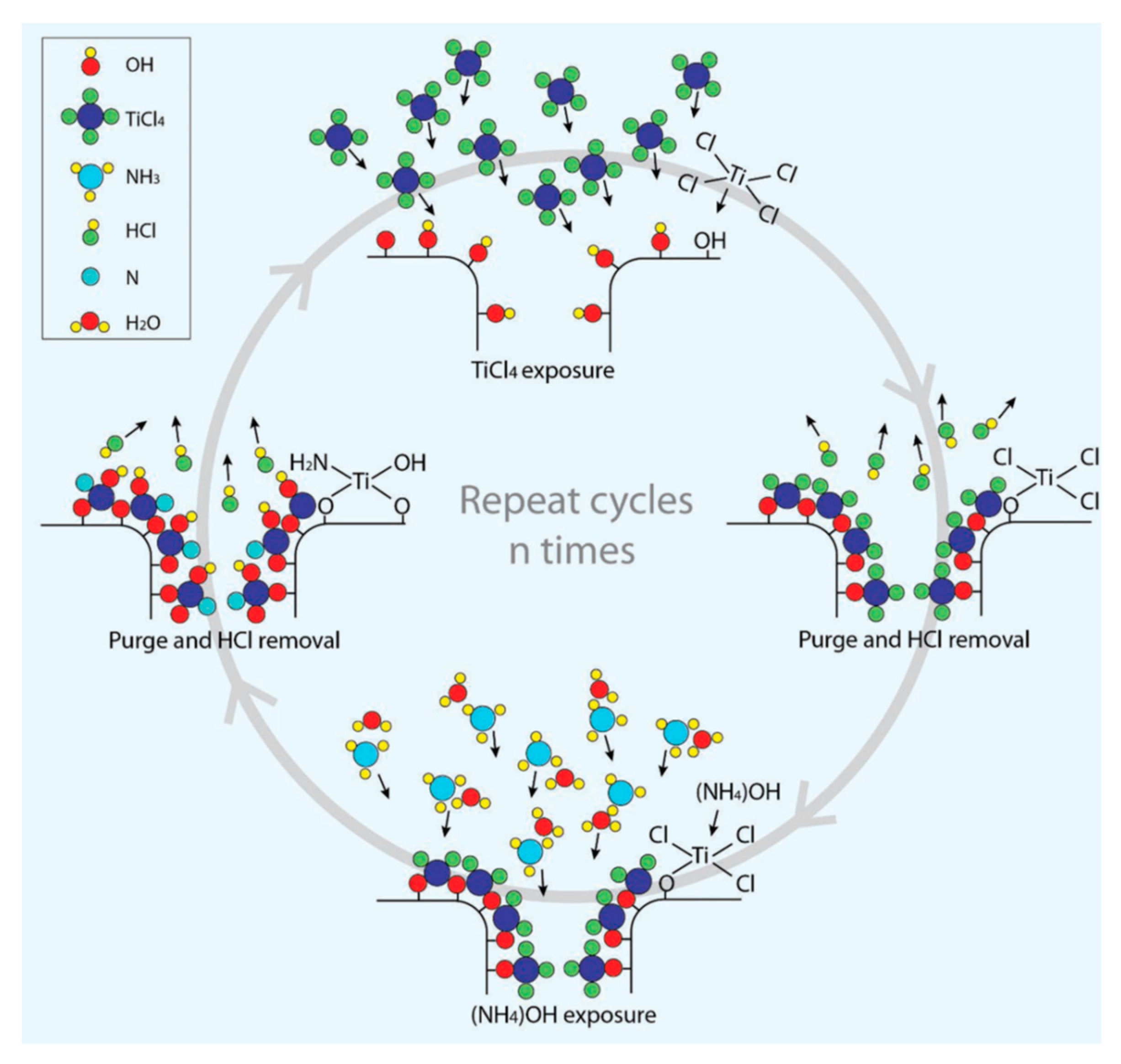
The atomic layer deposition (ALD) method is a recently developed and facile strategy for the element doping of semiconductors. Actually, ALD is a gas-phase deposition process based on alternate surface reactions of the substrates, and the ALD method possesses several advantages, such as good reproducibility, considerable conformality, and excellent uniformity [53]. Consequently, the ALD method is considered as a promising strategy for the preparation of doped and composite photocatalysts [54]. For example, Pore et al. [55] prepared a series of N-TiO2 films via employing the ALD processes. In this study, TiCl4 was used as the titanium precursor and there were two ALD cycles during the fabrication process: (i) a thin layer of TiN was grown from the TiCl4 and NH3; and (ii) TiO2 was deposited on the surface of TiN layer from TiCl4 and H2O, meanwhile the as-prepared TiN layer was part-oxidized to TiO2, thus resulting in the TiO2−xNx. Moreover, the nitrogen concentration of the obtained TiO2−xNx could be well controlled via changing the ratio of TiN and TiO2 deposition cycles. Similarly, Lee et al. [56] reported a facile and effective vapor-phase synthesis strategy to prepare a conformal N-TiO2 thin film based on the ALD process. As shown in Figure 7, the fabrication process of the corresponding N-TiO2 film involved four main steps: (i) pulse the TiCl4 vapor on the surfaces of a substrate to produce a monolayer of chemisorbed TiClx species; (ii) remove the remaining unreacted TiCl4 and corresponding HCl byproducts using nitrogen gas; (iii) NH4OH as the nitrogen source was subsequently pulsed to generate a mixture of gaseous H2O and NH3, which react with the as-prepared TiClx species to obtain the N-TiO2; and (iv) remove the unreacted precursors and HCl byproducts again. This cycle could be repeated to achieve the N-TiO2 film with the desired thickness. The as-prepared N-TiO2 exhibited significantly enhanced photocatalytic degradation performance for organic pollutants solely driven by the solar irradiation.
3.2.5. Sol-Gel and Combustion Method
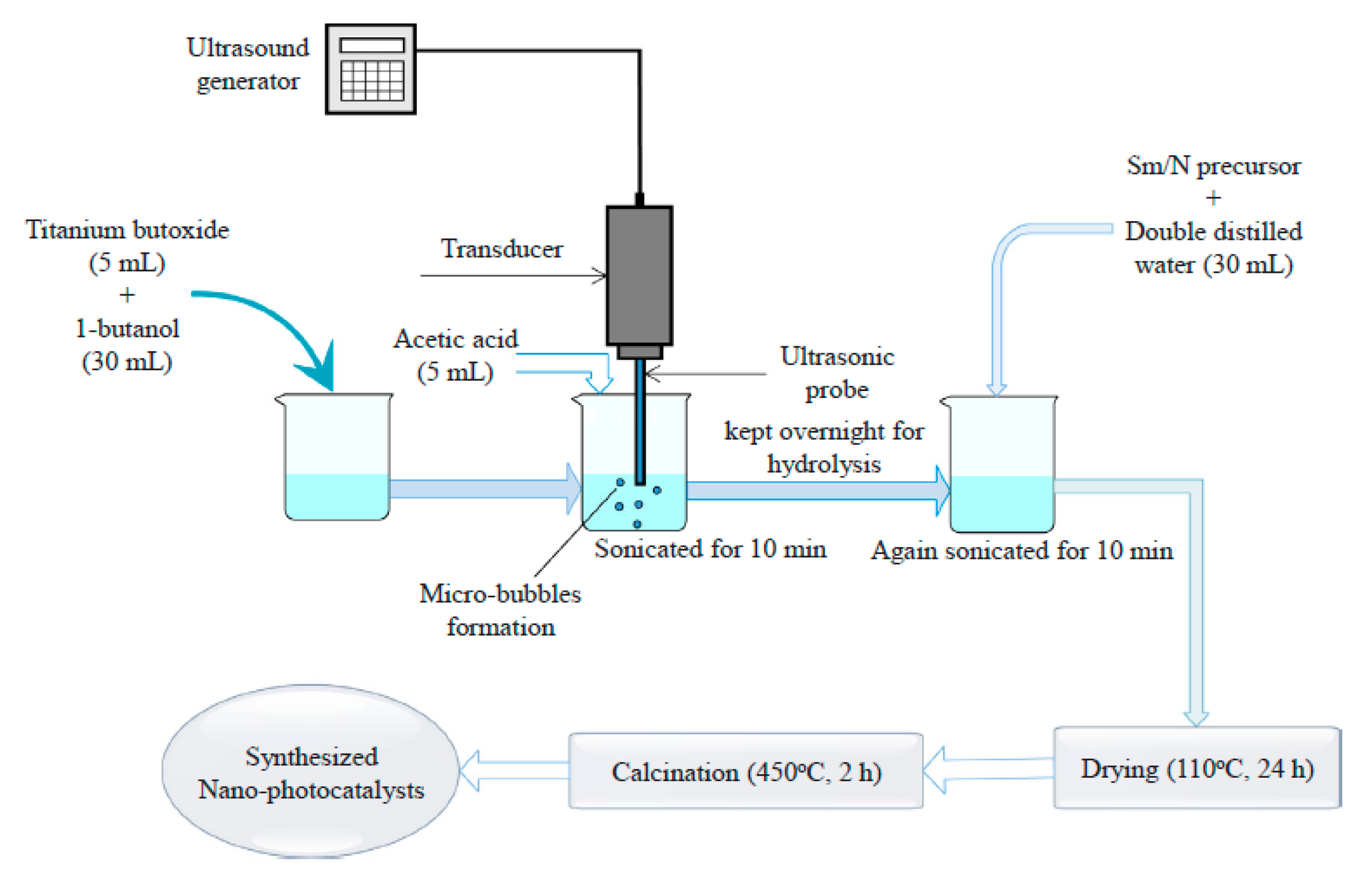
Compared with the abovementioned synthesis approaches, the sol-gel and combustion method is a facile and low-cost strategy for the preparation of various semiconductors and the corresponding hybrid semiconductors. With the merits of simplicity and the possibility of controlling the synthesis conditions, the sol-gel methods have been well developed and several extended sol-gel techniques have been invented to fabricate new types of semiconductor photocatalysts. For example, Albrbar et al. [57] reported the synthesis of a series of mesoporous anatase TiO2 powders doped by N, and S, as well as the N,S co-doped anatase TiO2 powder using a non-hydrolytic sol-gel process. During the gel synthesis process, titaniumtetrachloride and titaniumisopropoxide were used as the precursor of Ti, dimethylsulfoxide (DMSO) was used as the precursor of S, and NH3 was used as the precursor of N. For the preparation of S-doped TiO2, the obtained gel derived from the solvent of DMSO was calcined in air, while N and S co-doped TiO2 was obtained when the gel was annealed in the atmosphere of NH3. In addition, the pristine TiO2 and corresponding N-doped TiO2 was further obtained via calcining the gel derived from the solvent of cyclohexane in air and NH3, respectively. In their studies, the photocatalytic activities of the samples were evaluated via the degradation of dye C.I. Reactive Orange16 in water under the irradiation of visible light. The obtained results showed that the N-doped TiO2 exhibited better visible-light photocatalytic activity compared with the pristine TiO2 and S-doped TiO2. Similarly, the sol-gel method is also versatile enough to be combined with other materials synthesis techniques. Most recently, Rajoriya et al. [58] successfully fabricated a samarium (Sm) and nitrogen (N) co-doped TiO2 photocatalyst through an ultrasound-assisted sol-gel process (Figure 8), where they found that after doping TiO2 with Sm and N, the photocatalytic degradation performance of the TiO2 for 4-acetamidophenol was greatly improved owing to the significantly improved separation efficiency of the photo-generated electron–hole pair.
4. Heterojunctions Construction
Besides the abovementioned heteroatoms doping strategy, constructing heterojunctions in photocatalysts is also considered as one of the most promising approaches for improving the photocatalysis performance of semiconductors due to its feasibility and effectiveness for the spatial separation of electron–hole pairs. More specifically, the heterojunction is defined as the formed interface between two semiconductors with the unequal band structure, which can form band alignments [59,60]. In fact, there have been several types of heterojunction structures, which could be considered as the conventional heterojunction structures, and the new generation of heterojunction structures.
4.1. Conventional Heterojunctions
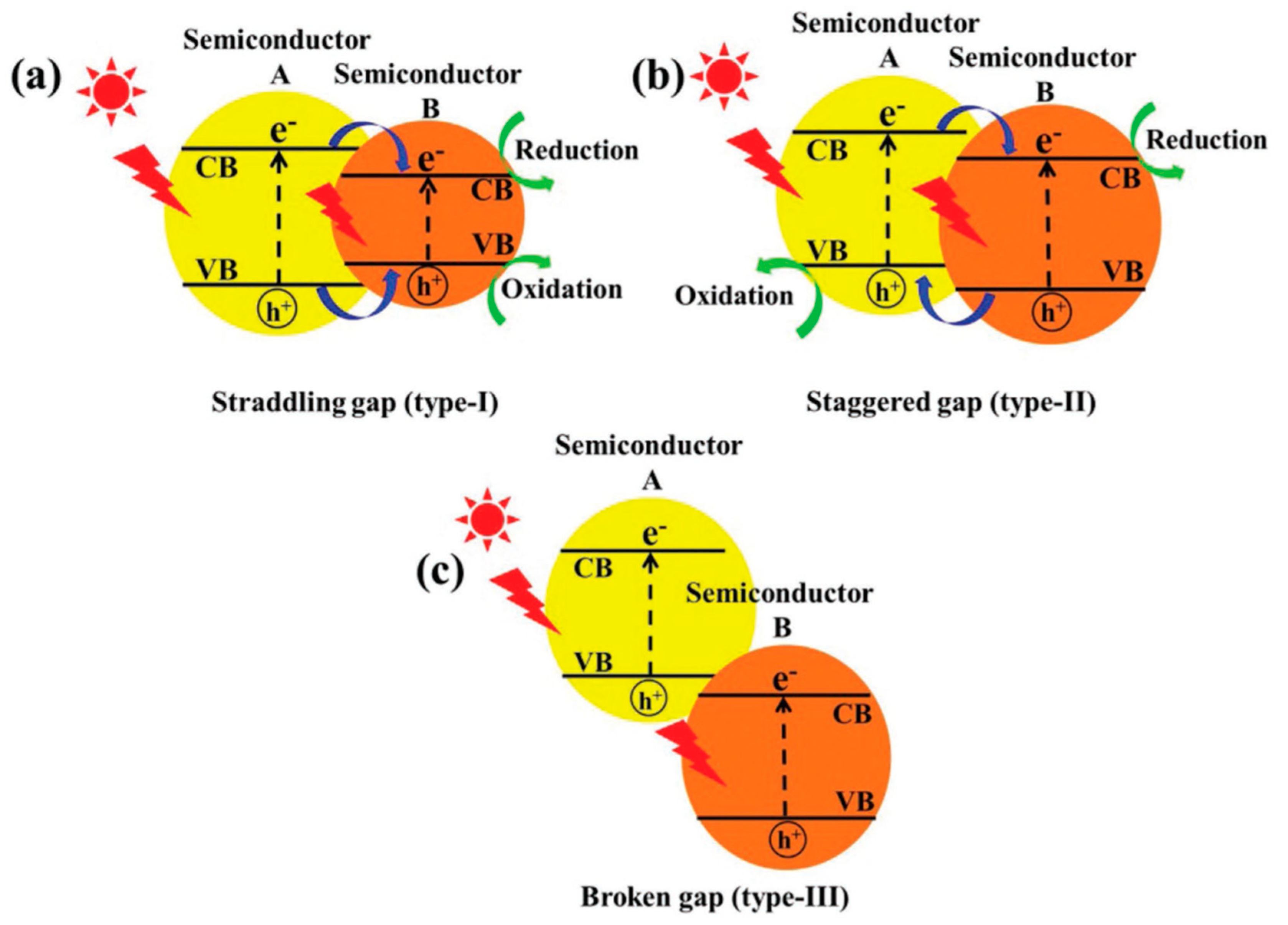
In general, the conventional heterojunctions can be classified as three types depending on the different band gaps of the composite semiconductors, which are type I with a straddling gap, type II with a staggered gap, and type III with a broken gap (Figure 9) [59]. As for the type I heterojunction, the VB and CB of semiconductor A are lower and higher than the corresponding VB and CB of semiconductor B, respectively. As a result, the photo-generated electrons and holes transfer to the CB and VB of semiconductor B, which is negative for the separation of electron–hole pairs. Moreover, the redox reaction of the composite semiconductors with a type I heterojunction will conduct on the surface of semiconductor B with a lower redox potential, therefore the redox ability of the whole photocatalyst may be suppressed. Meanwhile, in the composite semiconductor system with type II heterojunctions, the VB and CB of semiconductor A are higher than that of semiconductor B, thus the photo-generated electrons will migrate from the CB of semiconductor A to that of semiconductor B with a lower reduction potential, and the corresponding holes in the VB of semiconductor B will migrate to semiconductor A with a lower oxidation potential, thus a spatial separation of electron–hole pairs will be completed. However, the band gap of the two semiconductors will not overlap in the type III heterojunctions, and as a result, there is no transmission or separation of electrons and holes between semiconductor A and semiconductor B. Consequently, the type II heterojunction is the most effective structure for improving the photocatalysis performance of semiconductors, and has received a great deal of research attention.
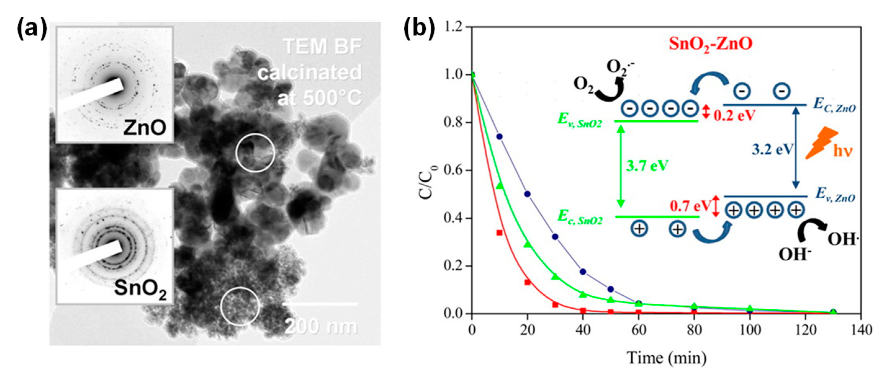
Up to now, several type-II heterojunction photocatalysts have been developed by creating two different phases in the same semiconductor, or directly compositing different semiconductors together [60,61]. For example, Yu et al. [62] once created the anatase-brookite dual-phase in a TiO2 photocatalyst to form a type-II heterojunction via hydrolyzing the titanium tetraisopropoxide in water and an ethanol-H2O mixture solution. They found that the co-presence of brookite and anatase phases in the TiO2 significantly enhanced the photocatalysis performance. After that, Uddin et al. [63] successfully fabricated the mesoporous SnO2-ZnO heterojunction photocatalysts using a two-step synthesis strategy. Furthermore, they had carefully examined the band alignment, the results showed that the obtained SnO2-ZnO heterojunction photocatalyst possessed a type-II band alignment and exhibited higher photocatalytic activity for the degradation of methyl blue in water than that of the individual SnO2 and ZnO nanocatalysts (Figure 10). Apart from the inorganic semiconductors, organic semiconductors could also be incorporated with the semiconductors to form the type-II heterojunction. For example, Shirmardi et al. [64] used polyaniline (PANI) as the organic semiconductor combined with ZnSe nanoparticles via a simple and cost-effective co-precipitation method in the ambient conditions. The obtained ZnSe/PANI nanocomposites exhibited obvious enhancement in the photocatalytic performance compared to that of the pristine ZnSe nanoparticles.
4.2. New Generation of Heterojunctions
Although the conventional type-II heterojunctions are capable of spatially separating the photo-generated electron–hole pairs, there remain several critical limitations, such as the relatively weak redox ability due to the lower reduction and oxidation potentials, and the suppressed migration of electrons and holes due to the electrostatic repulsion [59]. Recently, in order to overcome the abovementioned limitations, a new generation of heterojunctions have been developed, including the p-n heterojunctions, the surface heterojunctions, the Z-scheme heterojunctions, and the semiconductor/carbon heterojunctions. Here we will give a brief introduction of each kind of these newly developed heterojunctions.
4.2.1. p–n Heterojunctions
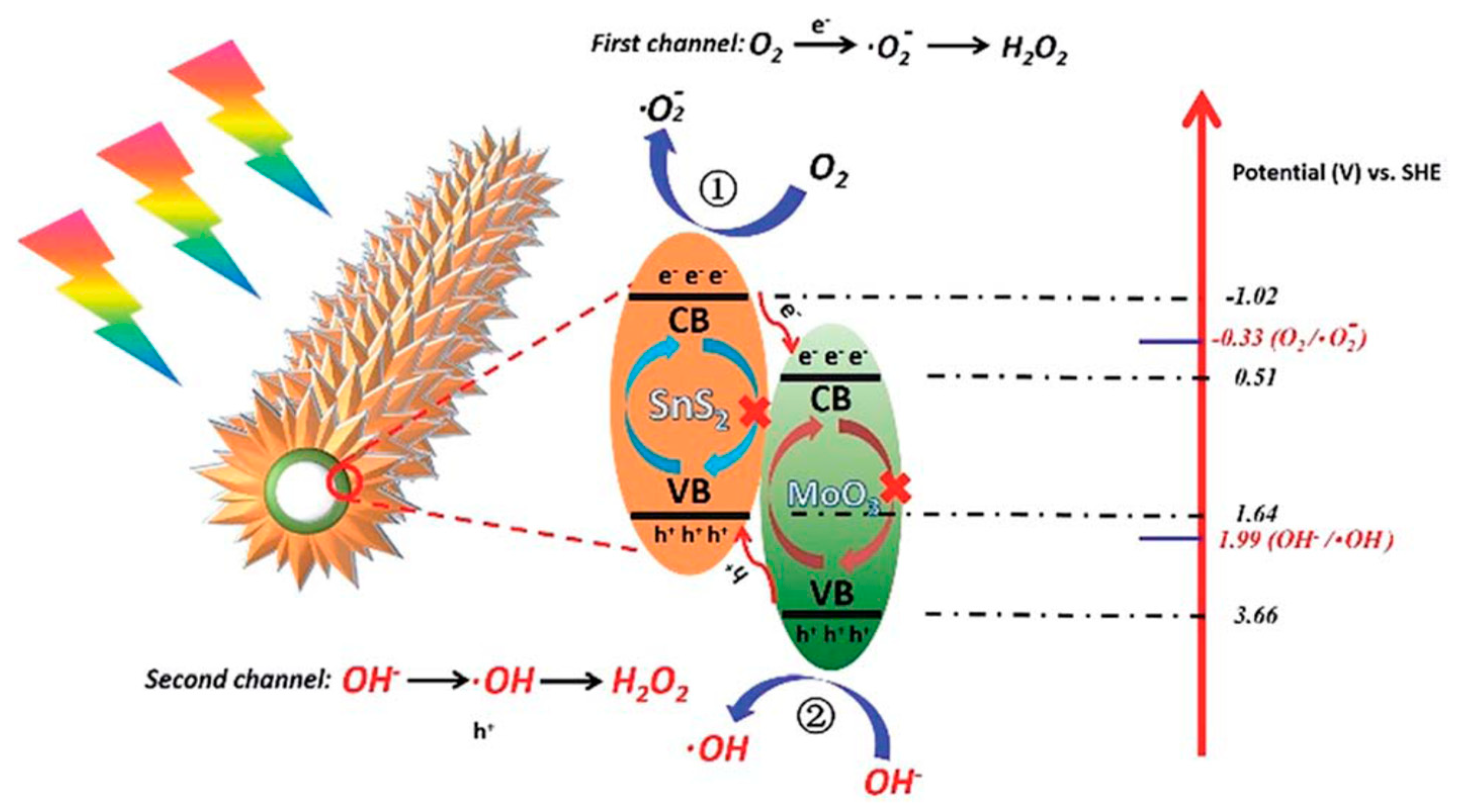
The p-n heterojunctions could be obtained by incorporating a p-type semiconductor with an n-type semiconductor, and it has been proved that the formation of p-n heterojunctions are effective for improving the photocatalytic performance of composite catalysts [65,66]. In general, before the irradiation of light, there is an internal electric field in the region closed to the p-n interface due to the electron–hole diffusion tendency of the composite semiconductors system with unequal Fermi levels [59,67]. Alternatively, when the composite semiconductors are irradiated by a light, and the energy state of the photon is beyond the band gaps of both p-type and n-type semiconductors, electron–hole pairs will be generated in the corresponding semiconductors. However, due to the presence of an internal electric field, the photo-generated electrons and holes will transfer to the CB of the n-type semiconductor and the VB of p-type semiconductor, respectively. Furthermore, it has been proved that this spatial separation of the photo-generated electron–hole pairs is much more efficient compared with that of conventional type-II heterojunction because of the synergy of the internal electric field and band alignment [59,68]. As a result, a variety of composite semiconductors with the p-n heterojunctions have been created for the application of photocatalysis. For example, Wen et al. [69] reported the fabrication of a BiOI/CeO2 p-n junction using a facile in situ chemical bath method. The result demonstrated that the BiOI/CeO2 composite with a mole ratio of 1:1 exhibited a superior photocatalytic performance for the decomposition of bisphenol A (BPA) and methylene orange under visible light irradiation. Most recently, as shown in Figure 11, our group reported a facile method for the preparation of SnS2/MoO3 hollow nanotubes based on the hydrothermal method [70]. The obtained SnS2/MoO3 hollow nanotubes exhibit a typical p-n heterojunction structure, and a synergistic effect between MoO3 and SnS2 was proven to yield an optimal hydrogen peroxide production performance.
4.2.2. Surface Heterojunctions
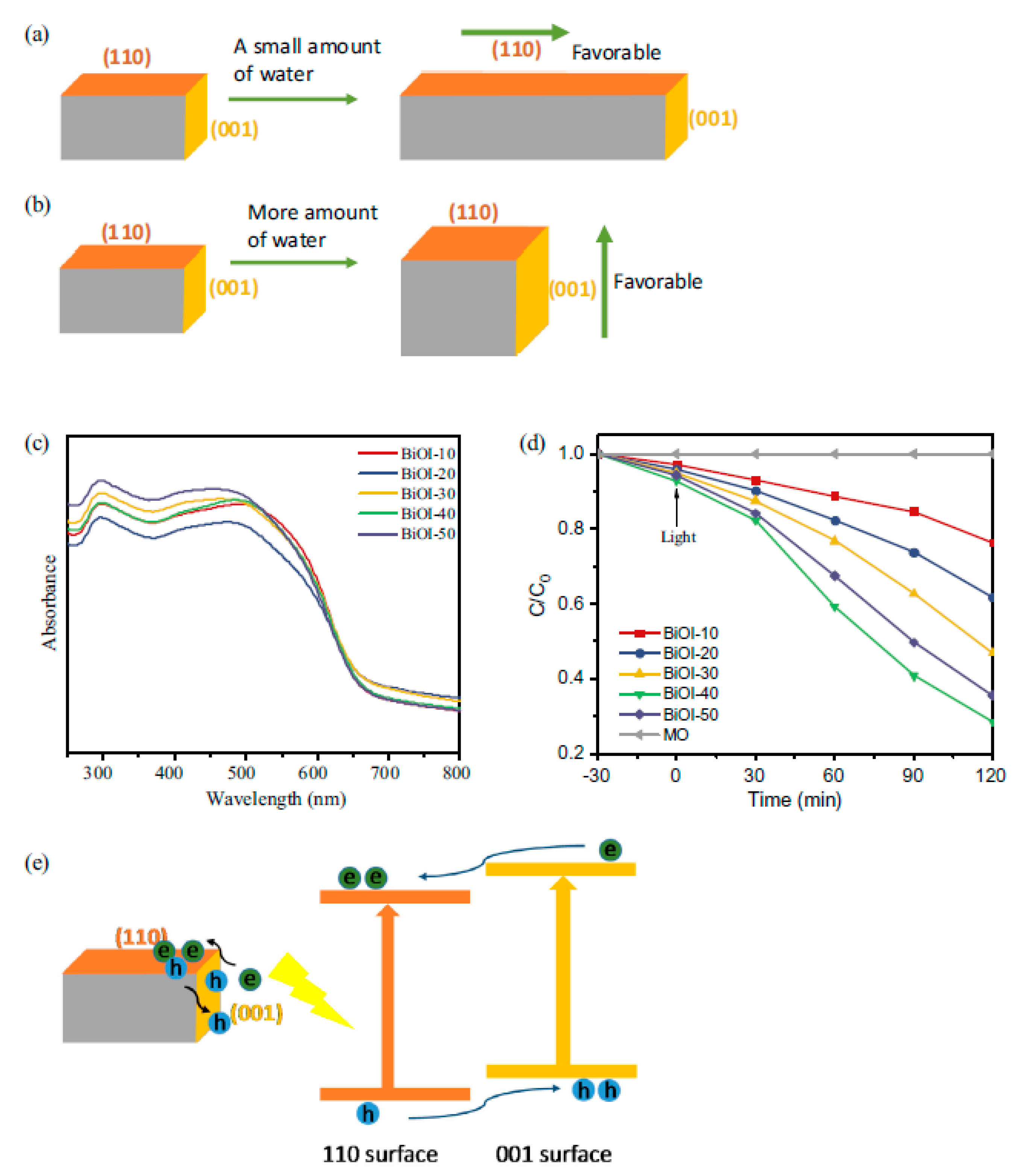
As reported before, a surface heterojunction can be created between two crystal facets of a single semiconductor [59,71]. For example, Yu et al. [72] proved that the formation of a heterojunction between the (001) and (101) facets in TiO2 contribute significantly toward the enhancement of photocatalytic activity. This method enables the construction of a heterojunction on the surface of a single semiconductor, which is less costly because only one semiconductor is used. They also demonstrate that there is an optimal ratio for the (001) and (101) facets in the anatase TiO2 for the improvement of its photocatalysis performance. Subsequently, Gao et al. [73] found that the surface heterojunction of TiO2 could be self-adjusted, and its photocatalytic activity could be significantly improved via combining a proper surface heterojunction with the Schottky junction. Apart from the TiO2, Bi-based semiconductors could also be employed for the design of photocatalysts with surface heterojunctions. Most recently, as shown in Figure 12, Lu et al. [74] synthesized a tetragonal BiOI photocatalyst by regulating the amount of water in the hydrolysis process at room temperature. The as-prepared photocatalyst possessed a typical surface heterojunction structure between (001) facets and (110) facets, and exhibited a promoted photocatalytic performance for the degradation of organic contaminants in water under visible light.
4.2.3. Z-Scheme Heterojunctions
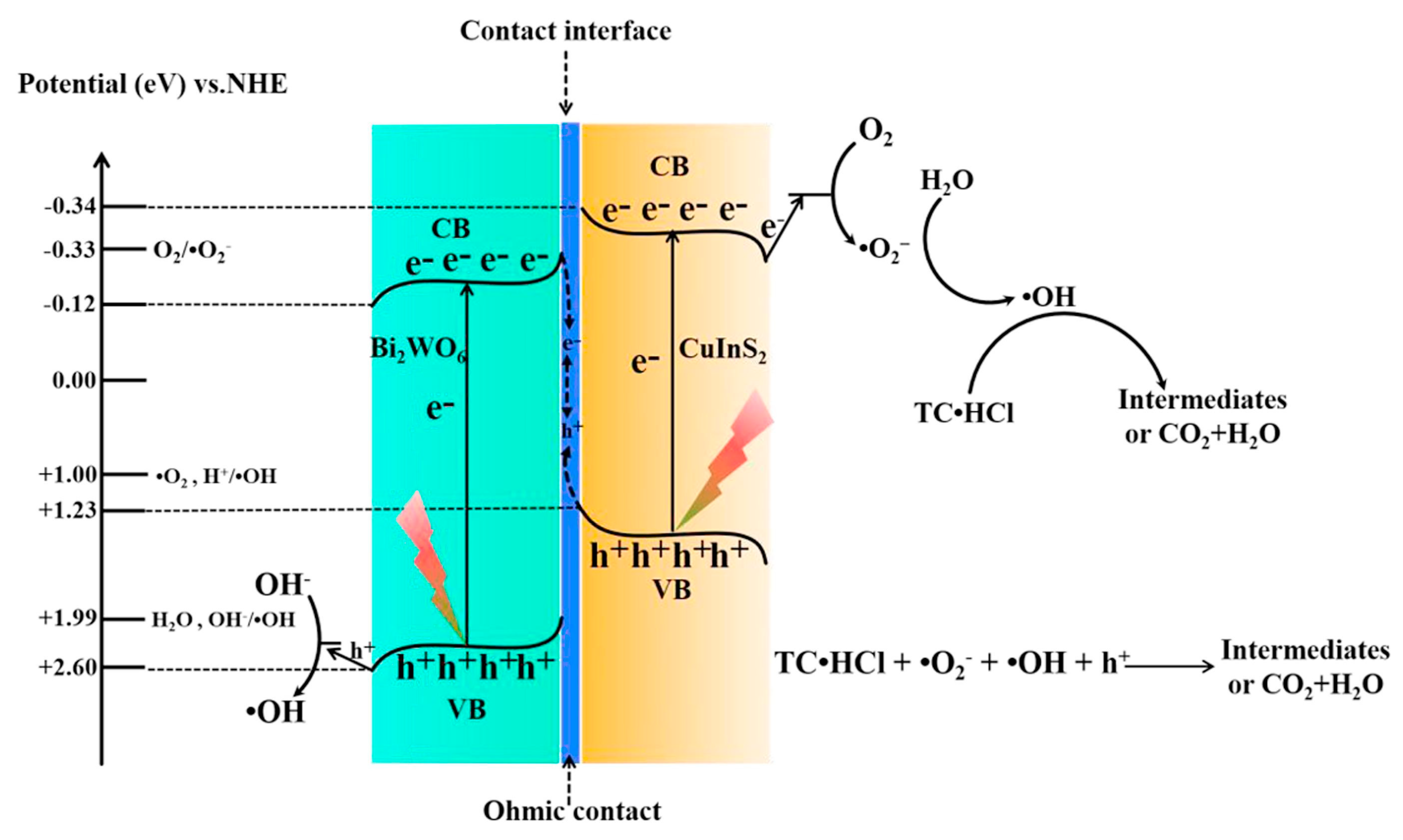
Z-scheme heterojunctions were constructed to overcome the limitation of the lower redox potential of the heterojunction systems. [59,75] In general, the Z-scheme heterojunction is composed of two different semiconductors and an electron acceptor/donor pair. During the photocatalysis process, the photo-generated electrons/holes will transfer from the matrix semiconductor to the coupled semiconductor through the electron acceptor/donor pair or an electron mediator. As a result, the electrons/holes will accumulate on different semiconductors with higher redox potentiasl, and an effective spatial separation of electron–hole pairs is also realized. Up to now, the Z-scheme heterojunctions have been well developed, and various photocatalysts with well-designed Z-scheme heterojunctions have been invented for the wastewater treatment. [75] For example, Wu et al. [76] reported the fabrication of the Ag2CO3/Ag/AgNCO composite photocatalyst via a simple in situ ion exchange method. The obtained composite photocatalyst possessed the Z-scheme heterojunction and exhibited a highly efficient degradation ratio of rhodamine B and the reduction of Cr (VI) under the driving of visible light. They proved that the significantly enhanced photocatalytic activity could be attributed to the low resistance for the interfacial charge transfer and desirable absorption capability. Recently, considering the relative high cost of the common used electron mediators (e.g., Pt, Ag, and Au), a new generation of Z-heterojunctions without the electron mediators have been invented for wastewater treatment, which is named as the direct Z-scheme system [59]. For example, Lu et al. [77] synthesized a CuInS2/Bi2WO6 composite catalyst with a direct Z-scheme heterojunction via the in situ hydrothermal growth of Bi2WO6 on the surface of CuInS2 networks. The obtained composite photocatalysts with an optimal Z-scheme exhibited a superior visible light degradation performance of the tetracycline hydrochloride in water than that of the pristine CuInS2 and Bi2WO6. The improved photocatalytic activity was attributed to the formed intimate interface contact, which ensured a good interfacial charge transfer ability (Figure 13).
4.2.4. Semiconductor/Carbon Heterojunctions
Carbonaceous nanomaterials have been widely employed for the design of novel photocatalysts due to their advantages of high surface area, good conductivity, and chemical stability. In general, the most commonly used carbonaceous materials for combining with semiconductors involves the carbon dots (CDs), carbon nanotubes (CNTs), and graphene [78].
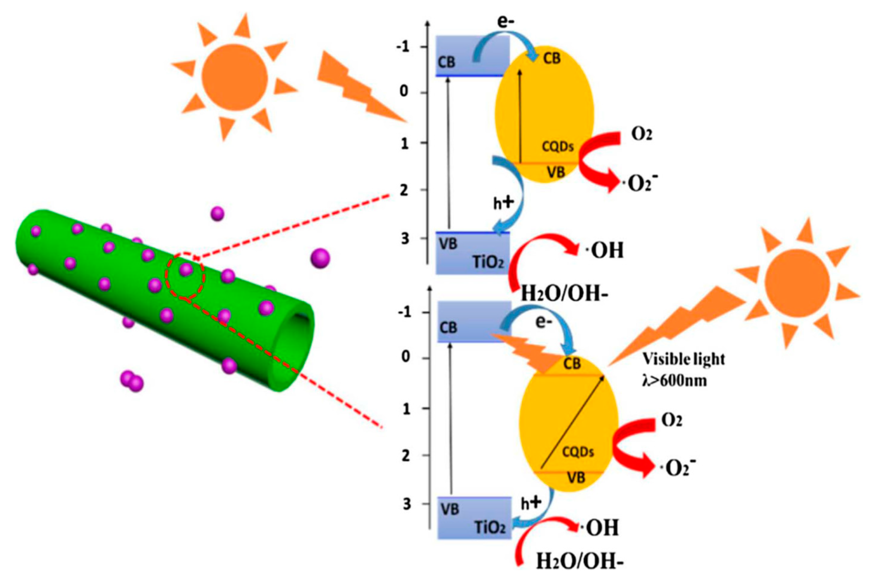
The CDs as typical nanocarbon materials have been widely used to enhance the photocatalytic activity of semiconductors owing to their intriguing optical and electronic properties, low chemical toxicity, adjustable photoluminescence, and the distinct quantum effect [79]. For example, Long et al. [80] used carbon dots (CDs) to couple with the BiOI with highly exposed (001) facets to form a composition of CDs/BiOI. Furthermore, the obtained CDs/BiOI composite exhibited a greatly improved photocatalytic activity for the degradation of organic dyes in water. It has been proved that the incorporated CDs in the semiconductor formed a CDs/BiOI heterojunction, which was able to construct numerous electron surface trap sites and was beneficial for enhancing the visible light absorption range as well as the charge separation. Recently, Zhao et al. [81] reported the fabrication of carbon quantum dots (CQDs)/TiO2 nanotubes (TNTs) composite via an improved hydrothermal method. The CQDs were incorporated on the surface of the TNTs, and played a vital role in improving the visible light photocatalytic performance of the composite. As shown in Figure 14, they demonstrated that there were three advantages for the formation of CQDs/TiO2: (i) the CQDs could effectively trap the photo-generated electrons from TNTs and suppress the recombination of electron-hole pairs, (ii) the up-conversion photoluminescence property of CQDs could further improve the visible light utilization efficiency of CQDs/TNTs, and (iii) the hetero-structure formed between the CQDs and the TNTs could prolong the life of the photogenerated electron and hole pairs.
CNTs are typical nanocarbon materials with highly sp2-ordered structures, and thus exhibit an excellent metallic conductivity, which could form a Schottky barrier junction between the CNT and semiconductors; as reported before, the Schottky barrier junction could effectively increase the recombination time of electron–hole pairs [78,82]. Moreover, CNTs could accept electrons in the composite system with semiconductors due to its large electron-storage capacity, which is beneficial for retarding or hindering the electron–hole recombination. As a result, a variety of semiconductor-CNT composite photocatalysts have been developed. For example, Miribangul et al. [83] prepared a TiO2/CNT composite via a simple hydrothermal method. The influence of the CNT concentration in the TiO2-CNT composites on their photocatalytic activity was investigated and the 0.3 wt % CNT content in TiO2/CNT composite could offer the highest photocatalytic degradation of Sudan (I) in UV–vis light. Apart from the TiO2, some of the other semiconductors can also be employed to composite with CNT, such as the CNT/LaVO4 composite photocatalyst developed by Xu et al. [84]. As shown in Figure 15, with the presence of CNT, the photocatalytic activity of a CNT/LaVO4 composite was greatly improved due to the synergistic effect between CNT and LaVO4, therefore the corresponding photocatalytic degradation rate of CNT/LaVO4 composite for organic contaminant is 2 times that of pure LaVO4.
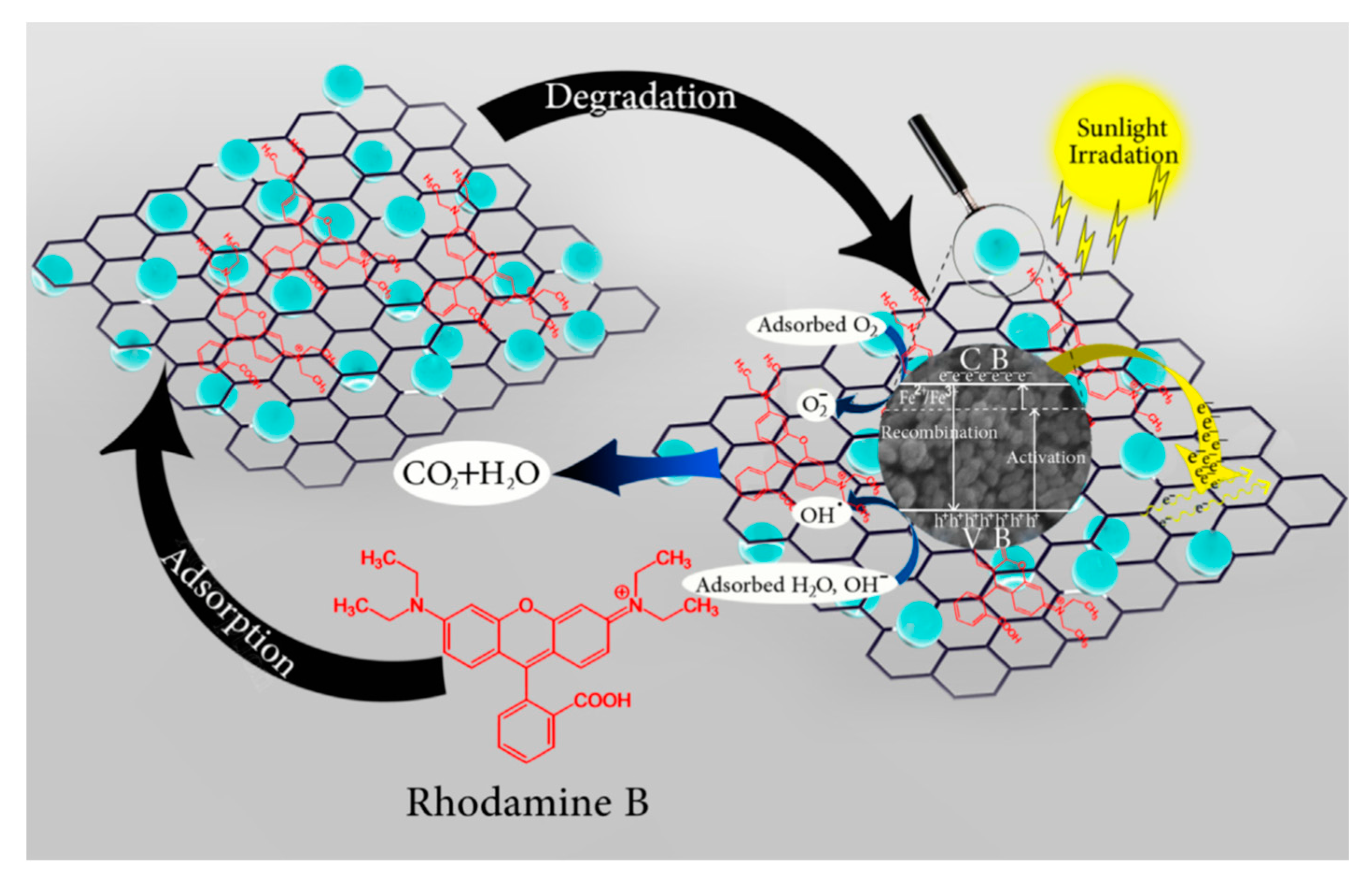
Recently, graphene as a newly developed nanocarbon material has attracted numerous research attention in the area of photocatalysts due to its extraordinary physical properties, including superior charge transport ability, unique optical properties, high thermal conductivity, large specific surface area, and good mechanical strength [78,85,86]. Up to now, a myriad of attempts has been carried out to couple the graphene with various semiconductors to further improve their photocatalytic activity. According to the previous reports, the first graphene composite semiconductor for photocatalysis was prepared by Zhang and co-workers [87]. They fabricated a TiO2 (P25)-graphene composite with a chemically bonding structure via a one-step hydrothermal reaction. As reported, there are three contributions of the graphene for the photocatalytic activity: (i) enhancing the adsorption capacity of pollutants, (ii) extending light absorption range, and (iii) improving charge transportation and separation efficiency. As a result, the photodegradation of the obtained TiO2 (P25)-graphene composite for methylene blue was significantly improved, and was superior to that of the bare P25 and the commonly reported P25-CNTs composite. After that, numerous photocatalysts based on the composite graphene-semiconductors have been invented for the treatment of wastewater. Most recently, in order to overcome the limitation of the poor homogenous dispersion of graphene, as shown in Figure 16, Isari et al. [88] created a ternary nanocomposite catalyst (Fe-doped TiO2/rGO) derived from Fe-doped TiO2 and reduced graphene oxide via a simple sol-gel method. They proved that the band gap of Fe-TiO2/rGO could be significantly decreased compared with that of the pristine TiO2, and the obtained Fe-doped TiO2/rGO exhibited an effective decontamination performance for rhodamine B in water.
5. Morphology Regulation of the Composite Photocatalysts
Apart from the intrinsic characteristics of semiconductors, the corresponding catalysts with different morphologies may result in different photocatalytic activities and different application processes [89]. Recently, morphology modification of the photocatalysts have attracted more and more attention owing to further improvements in their application performance, not only for the photocatalytic performance but also for the application techniques. With this in mind, in this section we will briefly summarize the recent achievements of the composite photocatalysts with different morphologies of 0D, 1D, 2D, and 3D materials.
5.1. Nanoparticles (0D)
Generally, the 0D materials are characterized as spherically shaped with nano-scaled dimensions. Nanoparticles as a typical 0D material have been widely used in the area of photocatalysis with the merits of large surface area, simple synthesis methods, and easy to be functionalized [90]. Up to now, several synthesis approaches have been invented, among which the sol-gel method, hydrothermal method, and solvothermal method could be the most-used techniques for the fabrication of 0D composite photocatalysts.
5.1.1. Sol-Gel Method
The sol-gel process is a commonly used and effective strategy for the preparation of various inorganic materials, especially for the metal oxides based on the corresponding precursors, and it has several merits including being low cost, processed at low-temperature, and the fine control of the product’s chemical composition. Therefore, the sol-gel process is one of the most-used techniques for the preparation of composite semiconductor photocatalysts [58]. For example, Vaiano et al. [91] immobilized the N-doped TiO2 nanoparticles (NPs) on glass spheres via the sol-gel method. Through regulating the synthesis conditions, and employing the Triton X-100 as the surface active agent, the obtained N-doped TiO2 NPs/glass spheres exhibited a good photocatalytic activity for methylene blue and eriochrome black-T in water under UV and visible light irradiation. Moreover, the composite catalyst was easy to be separated from the reaction mixture with a good durability. Recently, Chen et al. [92] prepared a Ni-Cu-Zn ferrite@SiO2@TiO2 composite via a simple sol-gel method. With the immobilization of Ag and magnetic ferrite, the composite photocatalysts exhibited comparatively good photodegradation performance for the methylene blue under a visible light source with lower power. Moreover, the composite catalysts can be easily separated using a magnet and can be reused well without significant loss of photocatalytic activity (Figure 17).
5.1.2. Hydrothermal Methods
The hydrothermal method is a wet-chemistry method for synthesizing single crystals. Through the hydrothermal method, a great deal of crystalline phases that are not stable at the melting point can be obtained [93]. As a result, numerous semiconductor nanoparticles with different surface morphologies and compositions can also be prepared using the hydrothermal method. As a representative work, Wu et al. [94] fabricated the F-doped flower-like TiO2 nanoparticle on the surface of Ti via a low-temperature hydrothermal process. They reported that the presence of HF in water and the hydrothermal reaction time play an important role in the formation of the F-doped flower-like TiO2 nanostructures. Through regulating the synthesis parameters, the obtained F-doped TiO2 flower-like nanomaterials exhibited a superior photoelectrochemical activity for the photodegradation of organic pollutants compared with P-25. They also demonstrated that the improved photoelectrochemical activity of the F-doped TiO2 flower-like nanomaterials was mainly due to the larger surface area and the enhanced visible light harvest capacity. Additionally, magnetic composite photocatalysts can also be synthesized using the hydrothermal method, such as the magnetic CoFe2O4/Ag/Ag3VO4 photocatalysts fabricated by Jing and co-workers [95]. During this study, the as-prepared CoFe2O4 nanoparticles were dispersed in the solutions with AgNO3 and Na3VO4, and the mixture suspensions were hydrothermally treated to prepare CoFe2O4/Ag/Ag3VO4 composites. Through controlling the weight ratios of CoFe2O4 in the composite system, the optimal CoFe2O4/Ag/Ag3VO4 composite exhibited significantly improved photocatalytic activity toward the degradation of various contaminants including methyl orange, tetracycline, and could even kill Escherichia coli solely under the driving of visible light. Moreover, with the advantage of having a good magnetic response property, the corresponding CoFe2O4/Ag/Ag3VO4 composite could be facilely collected from the water by applying an extra magnetic field (Figure 18).
5.2. Nanofibers/Nanorods (1D)
Recently, nanofibrous photocatalysts have been intensively studied owing to their unique long aspect ratio, large surface area, and being easily functionalized. Up to now, various strategies had been developed to synthesize the 1D materials with different morphology like: wires, belts, rods, tubes, and rings [61,89,96], among which, the hydrothermal method and electrospinning are the most-used techniques. Consequently, in this part, we present the development of composite semiconductors with nanofibrous morphology derived from the electrospinning method and hydrothermal method for the treatment of wastewater.
5.2.1. Hydrothermal Method
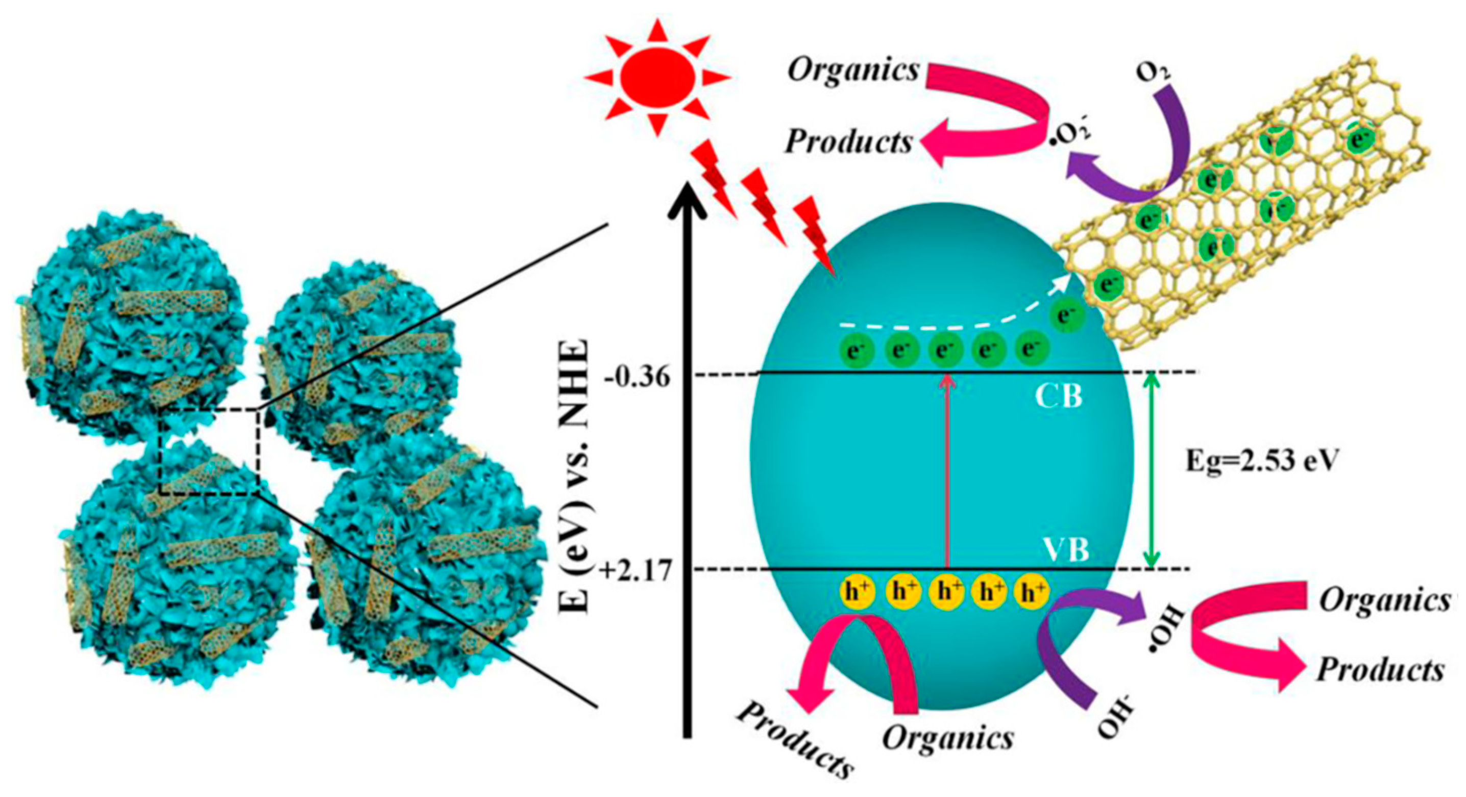
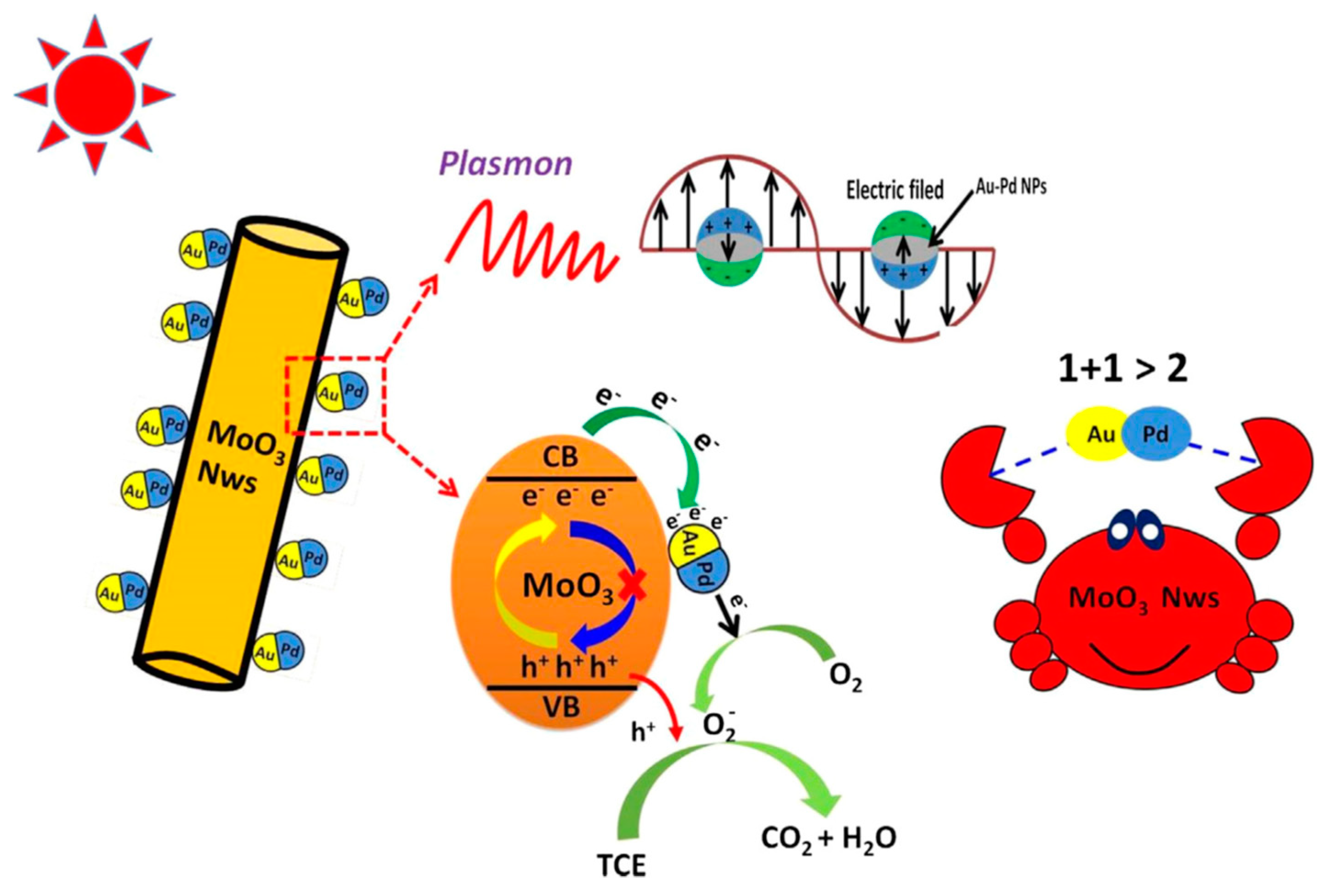
As mentioned above, the hydrothermal method is capable of synthesizing various inorganics with different morphologies, including the nanofibrous materials. For example, Yang et al. [97] once reported the fabrication of a novel TiO2 nanofibers with a shell of anatase nanocrystals based on the hydrothermal process. Actually, the whole fabrication process included three steps: First, the H2Ti3O7 nanofibers were obtained from the anatase TiO2 particles and NaOH solutions via hydrothermal method. After that, the as-prepared H2Ti3O7 nanofibers were treated using a dilute acid solution under certain hydrothermal condition to generate the anatase nanocrystal shell on the outside. Finally, the H2Ti3O7 phase was converted to TiO2(B) phase after a heat treatment while the anatase nanocrystal shell remained unchanged. Owing to the well-matched phase interfaces, which ensures the charge transfer across the interfaces, the recombination of electron-hole pairs was effectively suppressed and the corresponding photoactivity was significantly enhanced. Most importantly, they demonstrated that these nanofibrous photocatalysts possess specific surface areas similar to the commercial P25 powder, and the fibril morphology endowed them with a good recyclability from water, which is critically important in practical applications. Recently, our group also carried out a series of studies on the synthesis of nanofibrous photocatalysts via employing the hydrothermal method such as the bimetallic AuPd alloy nanoparticles deposited on MoO3 nanowires [98]. As shown in Figure 19, MoO3 nanowires were firstly prepared from Mo powder and H2O2 via the hydrothermal method. Then, the as-prepared MoO3 nanowires were used as the substrates to synthesize the MoO3/Au-Pd bimetallic alloy nanowires via a simple chemical reduction method. As expected, the MoO3/Au–Pd bimetallic alloy nanowires exhibited a good photocatalytic degradation performance for trichloroethylene (TCE) under the driving of visible light. Similarly, the composite nanowires could be easily separated from the reaction slurry in a short time after the reaction.
5.2.2. Electrospinning Method
Electrospinning is considered as a promising way to synthesize nanofibers with several advantages, such as easy operation, low cost, and scalable [99,100,101]. In general, there are four major parts in an electrospinning device: (i) an electrical power supplier, (ii) a metallic needle, (iii) syringes with the polymer solution, and (iv) a conductive collector. Meanwhile, several process parameters, such as the polymer-based solution concentration, the viscosity of solution, the flow rate of the syringe driver, and the electric field power, could also be well-regulated to manipulate the morphology of fibers. During the electrospinning process, the solution is injected through a metallic needle via a syringe with a constant pump speed. At the same time, a voltage is applied on the metallic needle; therefore, the solution droplet will be charged, and then a Taylor cone will be generated when the electronic force is enough to overcome the surface tension. Following this, a liquid jet is formed between the grounded collector and the needle. The generated jets will be stretched by an electrostatic repulsion force until it reaches the collector; meanwhile, the solvent will rapidly evaporate during this process. Finally, the jets are solidified and the corresponding nanofibers are collected on the collector [100].
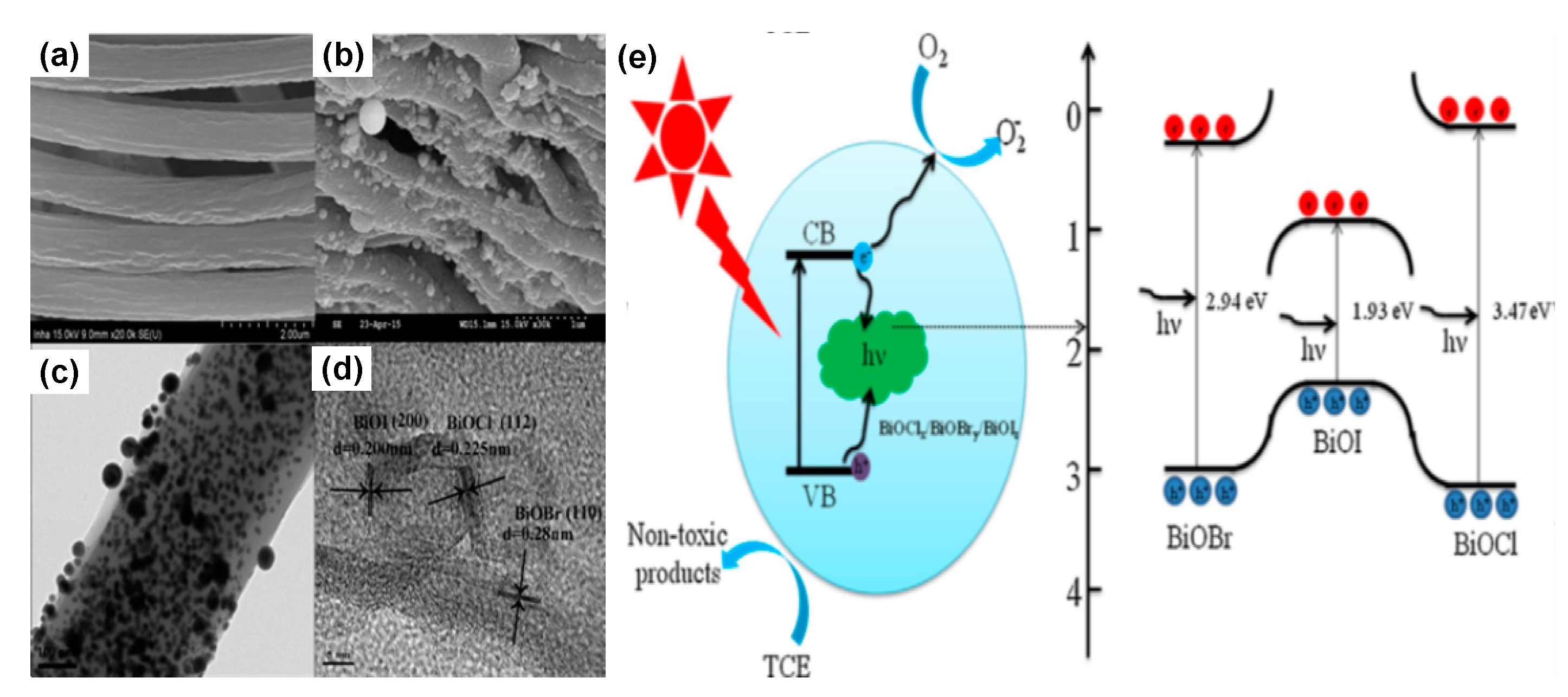
As for the applications of photocatalysis, high specific surface area is required to provide more active sites for the redox reaction. More specifically, electrospun nanofibers as forefront fibrous materials have attracted considerable research attention in the area of photocatalysis due to its several advantages of large surface area, extremely high aspect ratio, and ease of functionalization [102,103]. For example, Zhang et al. [104] reported the fabrication of a flexible and hierarchical mesoporous TiO2 nanoparticle (TiO2 NP) modified TiO2 nanofiber composites via the combination of electrospinning and in situ polymerization method. At first, flexible TiO2 nanofibers were prepared via the electrospinning and the subsequently consuming process with the dopant of yttrium. After that, the as-prepared TiO2 nanofibers were used as a template for the incorporation of TiO2 NPs by utilizing a bifunctional benzoxazine as the carrier through a calcination process in the N2 atmosphere. The as-prepared membranes exhibited remarkable photocatalytic activity towards organic dyes in water; moreover, it could be reused well via simply rinsing with water, and without time-consuming separation procedures owing to the long aspect ratio and good mechanical property of the composite nanofibers. In recent years, our group has carried out several works on the design of electrospun nanofibrous photocatalysts [105,106,107,108,109]. As a representative sample, a BiOCl0.3/BiOBr0.3/BiOI0.4/PAN composite fibrous catalyst was fabricated via combining the electrospinning and sol-gel method [109]. As shown in Figure 20, the obtained composite photocatalyst exhibited a typical fibril structure with a good uniformity, and the corresponding field emission transmission electron microscope (FE-TEM) image demonstrated a highly crystalline structure in the composite fibers with a clear lattice spacing relating to the (112) plane of BiOCl, the (110) plane of BiOBr, and the (200) plane of BiOI; therefore, a heterojunction structure was generated via a close contact of the composite semiconductors. After a visible-light driven photocatalysis performance evaluation, it was found that the obtained BiOCl0.3/BiOBr0.3/BiOI0.4/PAN fiber displayed the highest photocatalytic degradation performance of TCE. Moreover, it was concluded that the improved visible-light driven photocatalytic activity is caused by the interfacial contact of a heterojunction and the inhibition of the recombination rate of the electron–hole pairs.
5.3. Nanosheets (2D)
Semiconductor nanosheets are typical 2D nanomaterials and have attracted significant attention in the research area of photocatalysis for their larger surface area and tunable structures. Up to now, a great deal of semiconductor nanosheets have been synthesized via various strategies for different applications. The hydrothermal process is one of the most used strategies for the preparation of 2D semiconductor photocatalysts for the application of wastewater treatment [110]. Through the hydrothermal process, various nanosheets derived from a single semiconductor or multi-semiconductors could be synthesized. For example, Chen et al. [111] prepared TiO2-based nanosheets (TNS) via the alkaline hydrothermal treatment of commercial P25. They reported that the as-prepared TNS exhibited much higher specific surface area and much stronger adsorption for crystal violet molecules than the raw P25. Furthermore, the TNS could be effectively regenerated using a H2O2-assisted photocatalysis process, showing great potential for dealing with the high-chroma dye wastewater. Besides TiO2, various nanosheets derived from different semiconductors could also be fabricated using a hydrothermal process, such as the WO3 nanosheet/K+Ca2Nb3O10− ultrathin nanosheet synthesized by Ma et al. [112] via a facile hydrothermal assembly of WO3 nanosheets and ultrathin K+Ca2Nb3O10− nanosheets. They demonstrated that the composite nanosheets possess 2D/2D heterojunctions and display remarkably enhanced photocatalytic activity compared to the pristine WO3 and K+Ca2Nb3O10− nanosheets, which were mainly caused by the strongly coupled hetero-interfaces that provided more active sites for reactions and band structure. Additionally, some other methods, such as the solvothermal or photo-reduction methods, could also be employed for the preparation of composite nanosheets. For example, Wang et al. [113] fabricated the Bi12O15Cl6 nanosheets with a narrowed band gap via a simple and facile solvothermal method followed by a simple thermal treatment. The obtained Bi12O15Cl6 nanosheets exhibited a good photocatalytic degradation performance of bisphenol A solely under the driving of visible light, and the reaction rate of the composite nanosheets was 13.6 and 8.7 times faster than those of BiOCl and TiO2 (P25), respectively. In addition, the as-prepared Bi12O15Cl6 nanosheets possessed good stability and recyclability during the photocatalytic process. As shown in Figure 21, our group recently developed a Pt/BiOI composite nanosheet via a photo-reduction method in ambient conditions [114], where the as-prepared Pt/BiOI composites exhibited a flower-like structure and could effectively photocatalytically degrade the rhodamine B and phenol under visible-light irradiation (λ > 420 nm), where the degradation rate was superior to that of pure BiOI. Moreover, it was found that the content of Pt in the composite plays a vital important role on the photoactivity, and it was found that the optimal ratio of Pt to BiOI in the composite was 3%. It was concluded that the enhanced photocatalytic activity of the Pt/BiOI composite was caused by the superior electron transfer ability with the presence of an appropriate amount of Pt.
5.4. Frameworks (3D)
In recent years, there have been a great number of works reporting a new generation of composite photocatalysts with 3D frameworks [115]. Actually, the 3D photocatalysts with well-deigned frameworks show great advantages such as a large specific surface area, high adsorptive capacity, good structure stability, good mass transfer ability, and a large number of exposed active sites, which make them promising candidates for the highly efficient photodegradation of contaminants in water. In general, the 3D composite photocatalysts could be obtained via two approaches, which are to directly construct a photocatalyst with 3D frameworks (type I), or compositing the photocatalysts with a template with 3D frameworks (type II).
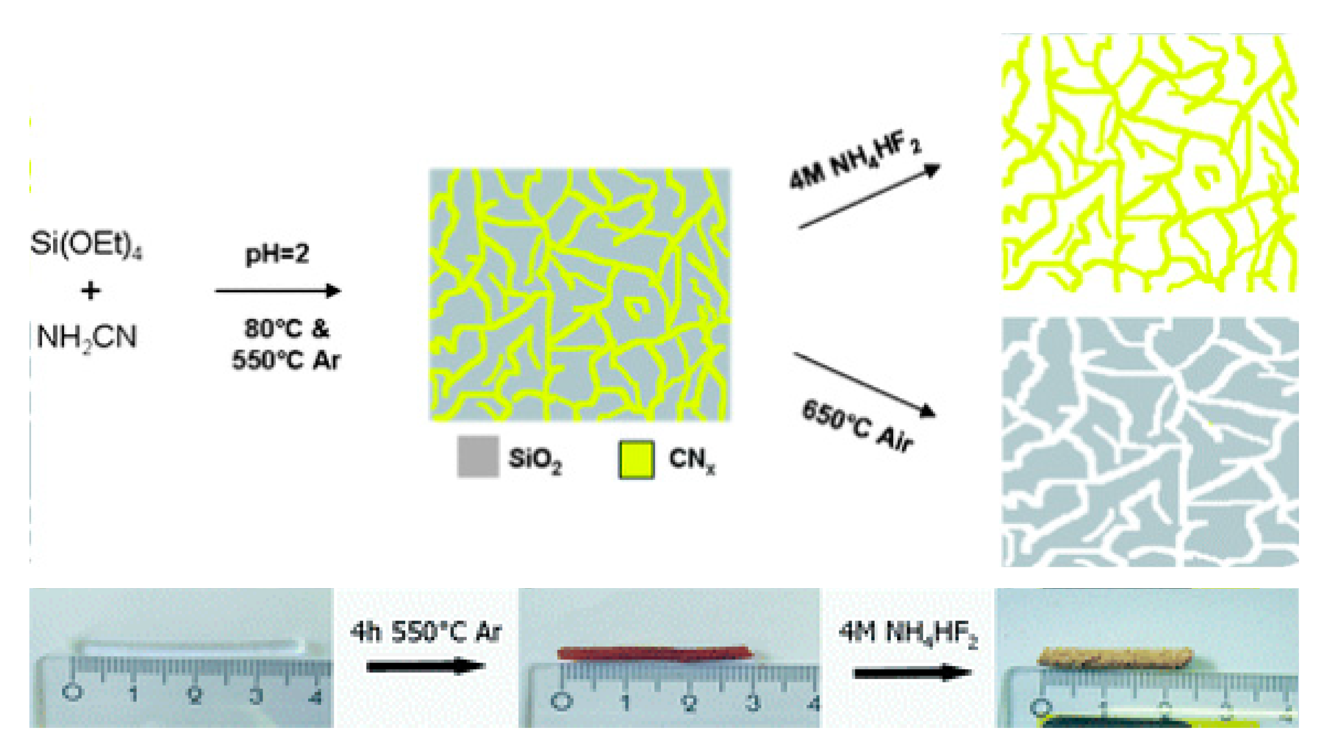
Through employing the commonly reported synthesis methods of various 3D frameworks, such as the sol–gel process, in situ assembly, and template methods, various 3D photocatalysts with different characteristics have be fabricated [116]. The sol-gel process is a well-developed strategy to synthesize aerogels, and some of the produced aerogels, such as the SiO2 aerogels, have been commercialized [117]. In general, there are two stages for the sol-gel process method: first, a precursor (e.g., metal alkoxide) is subjected to the hydrolysis and condensation reactions to form a wet gel, during which time, numerous networks are generated between the alkoxide groups; subsequently, the formed wet gels are sufficiently dried to obtain aerogels. As a matter of course, a photocatalytic aerogel can be obtained using a metal alkoxide precursor with an appropriate photocatalytic activity. For example, Dagan et al. [118] prepared a series of highly porous TiO2 aerogels via the sol-gel method and they also proved that the photocatalytic degradation performance of the TiO2 aerogels for organic contaminants is much better than that of a commercial TiO2 (P25). Besides, various photoactive metal oxides, metal silylamide, or their composite aerogels have been developed. However, due to the limitation of sol-gel processes, some metal oxides or metal chalcogenides are not able to be synthesized into aerogels, and the obtained aerogel photocatalysts usually suffer from low crystallinity. Therefore, a new generated strategy, namely an assembly method, has been invented to construct aerogels based on various nanoscale units with different morphologies and chemical properties. As reported before [116], there are three typical steps for the assembly process: (i) fabrication of the building blocks, (ii) preparing the dispersion of the building blocks with appropriated concentration, and (iii) solidified the suspension of building blocks to form a 3D monolith. Based on this principle, Heiligtag et al. [119] developed a 3D framework Au-TiO2 photocatalysts with a preformed TiO2 nanoparticles as the blocking units without using any templates. Through modifying the surface of anatase TiO2 nanoparticles with trizma, the nanoparticles undergo an oriented attachment process during gelation and finally result in well-bonded networks. Moreover, based on the above-mentioned aerogel synthesis methods, various phototcatalytic aerogels can also be prepared via employing the preformed aerogels as the templates, such as a C3N4 aerogel that was fabricated by Kailasam and co-workers [120] via preparing a C3N4/SiO2 composite aerogel based on the sol-gel method at first, and then remove the SiO2 via treating the composite in 4 M NH4HF2 (Figure 22).
As for the fabrication of type II 3D photocatalysts, an appropriate 3D porous substrate should be prepared before loading the active substance on its frameworks. Considering the requirements for high photoreactivity and good service performance, the aerogels/hydrogels derived from ceramics or carbon are mostly preferred. For example, Li et al. [121] fabricated a ternary magnetic composite of Fe3O4@TiO2/SiO2 aerogel via combining the sol-gel process and a hydrothermal treatment. During the fabrication process, Fe3O4 microspheres were first synthesized via the hydrothermal method; after that, Fe3O4@TiO2 core shell microspheres were fabricated via an in situ reaction method. The used SiO2 aerogel was derived from the industrial fly ash via a common sol-gel method. Finally, the as-prepared Fe3O4@TiO2 core shell microspheres and SiO2 aerogel were combined via the hydrothermal method. According to their report, the obtained Fe3O4@TiO2/SiO2 aerogel exhibited an enhanced photocatalytic activity for the degradation of rhodamine B dye under visible light irradiation, and the aerogel could be facilely collected after the reaction due to its good magnetic separation performance. Interestingly, as shown in Figure 23, Jiang et al. [122] recently developed a separation-free PANI/TiO2 3D hydrogel for the continuous photocatalytic degradation of various contaminants in water. In their studies, the PANI hydrogel with 3D frameworks was synthesized via the polymerization of aniline. During the gelling process, the TiO2 nanoparticles (P25) were incapsulated in the hydrogels. As a result, the obtained PANI/TiO2 composite hydrogel exhibited an intriguing capacity for removing organic contaminants from water, which was mainly caused by the synergistic effect of adsorption enrichment of hydrogel and the in situ photocatalytic degradation of TiO2. Moreover, the presented separation-free characteristics in the obtained bulk materials indicate a good recyclability of the composite hydrogel.
6. Summary and Perspectives
In summary, in order to address the worldwide concerned issues of water pollutions, various photocatalysis processes based on different photocatalysts have been developed; meanwhile, numerous efforts have been made to further improve the photocatalytic activity of the catalysts based on the semiconducors. In this review, the recent progress in the development of composite semiconductor photocatalysts for wastewater treatment is presented, including the most-used strategies to narrow the band gap of semiconductors, to retard the recombination of the photo-generated electron-hole pairs, to enhance the visible light adsorption capacity, as well as to increase the reaction ratio between the photocatalysts and contaminants. Moreover, the composite catalyts with different morphologies and the corresponding photocatlytic performance were also summarized.
Although great development of the photocatalysis process has been obtained, there are still several problems yet to be addressed to further improve the practical application performance of the photocatalysis. Therefore, some plausible perspectives for the developing trend of composite photocatalysts for the wasterwater treatment are proposed based on the presented studies: (i) the existing synthesis methods are relative complex, high cost, and harmful to the environment to some degree, thus a more facile, highly efficent, and green method is anticipated; (ii) the mechanism of the composite semicondutor photocatalysts are still confusing and some of them are unpersuasive, therefore much more effort is needed for the basic studies of the catalytic mechanisms; and (iii) the practical use are limitted because the collection and reuse of the catalysts in water are still inconvenient due to their small size and poor mechanical property, therefore novel photocatalysts with easy collection property or new hybrid devices based on the composite of photocatalysts with selected substrates (e.g., polymers, metals) are proposed. Finally, we anticipate that this review can provide some useful guidance for the design of next generation of photocatlysts for the wastewater remediation.
Funding
This work was supported by the Technology Development Program (S2598148) funded by the Ministry of SMEs and Startups (MSS, Korea) and the Commercialization Promotion Agency for R&D Outcomes (COMPA) funded by the Ministry of Science and ICT (MSIT) [2018_RND_002_0064, Development of 800 mAh/g pitch carbon coating.
Acknowledgments
This work was supported by the Technology Development Program (S2598148) funded by the Ministry of SMEs and Startups (MSS, Korea) and the Commercialization Promotion Agency for R&D Outcomes (COMPA) funded by the Ministry of Science and ICT (MSIT) [2018_RND_002_0064, Development of 800 mAh/g pitch carbon coating.
Conflicts of Interest
The authors declare no conflict of interest.
References
- Carpenter, S.R.; Caraco, N.F.; Correll, D.L.; Howarth, R.W.; Sharpley, A.N.; Smith, V.H. Nonpoint pollution of surface waters with phosphorus and nitrogen. Ecol. Appl. 1998, 8, 559–568. [Google Scholar] [CrossRef]
- Jarup, L. Hazards of heavy metal contamination. Br. Med. Bull. 2003, 68, 167–182. [Google Scholar] [CrossRef] [PubMed] [Green Version]
- Dudgeon, D.; Arthington, A.H.; Gessner, M.O.; Kawabata, Z.I.; Knowler, D.J.; Leveque, C.; Naiman, R.J.; Prieur-Richard, A.H.; Soto, D.; Stiassny, M.L.J.; et al. Freshwater biodiversity: Importance, threats, status and conservation challenges. Biol. Rev. 2006, 81, 163–182. [Google Scholar] [CrossRef] [PubMed]
- Ribeiro, A.R.; Nunes, O.C.; Pereira, M.F.R.; Silva, A.M.T. An overview on the advanced oxidation processes applied for the treatment of water pollutants defined in the recently launched Directive 2013/39/EU. Environ. Int. 2015, 75, 33–51. [Google Scholar] [CrossRef] [PubMed] [Green Version]
- Kolpin, D.W.; Furlong, E.T.; Meyer, M.T.; Thurman, E.M.; Zaugg, S.D.; Barber, L.B.; Buxton, H.T. Pharmaceuticals, hormones, and other organic wastewater contaminants in US streams, 1999-2000: A national reconnaissance. Environ. Sci. Technol. 2002, 36, 1202–1211. [Google Scholar] [CrossRef] [PubMed]
- Schwarzenbach, R.P.; Escher, B.I.; Fenner, K.; Hofstetter, T.B.; Johnson, C.A.; von Gunten, U.; Wehrli, B. The challenge of micropollutants in aquatic systems. Science 2006, 313, 1072–1077. [Google Scholar] [CrossRef]
- Radjenovic, J.; Sedlak, D.L. Challenges and opportunities for electrochemical processes as next-generation technologies for the treatment of contaminated water. Environ. Sci. Technol. 2015, 49, 11292–11302. [Google Scholar] [CrossRef]
- Jiang, J.Q. The role of coagulation in water treatment. Curr. Opin. Chem. Eng. 2015, 8, 36–44. [Google Scholar] [CrossRef]
- Lekang, O.I.; Bomo, A.M.; Svendsen, I. Biological lamella sedimentation used for wastewater treatment. Aquac. Eng. 2001, 24, 115–127. [Google Scholar] [CrossRef]
- Ali, I. Water treatment by adsorption columns: Evaluation at ground level. Sep. Purif. Rev. 2014, 43, 175–205. [Google Scholar] [CrossRef]
- Oe, T.; Koide, H.; Hirokawa, H.; Okukawa, K. Performance of membrane filtration system used for water treatment. Desalination 1996, 106, 107–113. [Google Scholar] [CrossRef]
- Joss, A.; Zabczynski, S.; Gobel, A.; Hoffmann, B.; Loffler, D.; McArdell, C.S.; Ternes, T.A.; Thomsen, A.; Siegrist, H. Biological degradation of pharmaceuticals in municipal wastewater treatment: Proposing a classification scheme. Water Res. 2006, 40, 1686–1696. [Google Scholar] [CrossRef] [PubMed]
- Mamba, G.; Mishra, A. Advances in magnetically separable photocatalysts: Smart, recyclable materials for water pollution mitigation. Catalysts 2016, 6, 34. [Google Scholar] [CrossRef]
- Lee, S.Y.; Park, S.J. TiO2 photocatalyst for water treatment applications. J. Ind. Eng. Chem. 2013, 19, 1761–1769. [Google Scholar] [CrossRef]
- Van der Hoek, J.P.; Bertelkamp, C.; Verliefde, A.R.D.; Singhal, N. Drinking water treatment technologies in Europe: State of the art-challenges-research needs. J. Water Supply Res. Technol.-Aquac. 2014, 63, 124–130. [Google Scholar] [CrossRef]
- Gogate, P.R.; Pandit, A.B. A review of imperative technologies for wastewater treatment I: Oxidation technologies at ambient conditions. Adv. Environ. Res. 2004, 8, 501–551. [Google Scholar] [CrossRef]
- Oturan, M.A.; Aaron, J.J. Advanced oxidation processes in water/wastewater treatment: Principles and applications. a review. Crit. Rev. Environ. Sci. Technol. 2014, 44, 2577–2641. [Google Scholar] [CrossRef]
- Pelaez, M.; Nolan, N.T.; Pillai, S.C.; Seery, M.K.; Falaras, P.; Kontos, A.G.; Dunlop, P.S.M.; Hamilton, J.W.J.; Byrne, J.A.; O’Shea, K.; et al. A review on the visible light active titanium dioxide photocatalysts for environmental applications. Appl. Catal. B-Environ. 2012, 125, 331–349. [Google Scholar] [CrossRef] [Green Version]
- Comninellis, C.; Kapalka, A.; Malato, S.; Parsons, S.A.; Poulios, L.; Mantzavinos, D. Advanced oxidation processes for water treatment: Advances and trends for R&D. J. Chem. Technol. Biot. 2008, 83, 769–776. [Google Scholar]
- Sansaniwal, S.K.; Sharma, V.; Mathur, J. Energy and exergy analyses of various typical solar energy applications: A comprehensive review. Renew. Sustain. Energy Rev. 2018, 82, 1576–1601. [Google Scholar] [CrossRef]
- Mills, A.; Davies, R.H.; Worsley, D. Water-purification by semiconductor photocatalysis. Chem. Soc. Rev. 1993, 22, 417–425. [Google Scholar] [CrossRef]
- Mills, A.; LeHunte, S. An overview of semiconductor photocatalysis. J. Photochem. Photobiol. A Chem. 1997, 108, 1–35. [Google Scholar] [CrossRef]
- Fujishima, A.; Honda, K. Electrochemical photolysis of water at a semiconductor electrode. Nature 1972, 238, 37. [Google Scholar] [CrossRef] [PubMed]
- Schneider, J.; Matsuoka, M.; Takeuchi, M.; Zhang, J.L.; Horiuchi, Y.; Anpo, M.; Bahnemann, D.W. Understanding TiO2 photocatalysis: Mechanisms and materials. Chem. Rev. 2014, 114, 9919–9986. [Google Scholar] [CrossRef] [PubMed]
- Tong, H.; Ouyang, S.X.; Bi, Y.P.; Umezawa, N.; Oshikiri, M.; Ye, J.H. Nano-photocatalytic materials: Possibilities and challenges. Adv. Mater. 2012, 24, 229–251. [Google Scholar] [CrossRef] [PubMed]
- An, H.Z.; Du, Y.; Wang, T.M.; Wang, C.; Hao, W.C.; Zhang, J.Y. Photocatalytic properties of BiOX (X = Cl, Br, and I). Rare Metals 2008, 27, 243–250. [Google Scholar] [CrossRef]
- Azeez, A.A.; Rhee, K.Y.; Park, S.J.; Hui, D. Epoxy clay nanocomposites—Processing, properties and applications: A review. Compos. Part B-Eng. 2013, 45, 308–320. [Google Scholar] [CrossRef]
- Dhand, V.; Mittal, G.; Rhee, K.Y.; Park, S.J.; Hui, D. A short review on basalt fiber reinforced polymer composites. Compos. Part B-Eng. 2015, 73, 166–180. [Google Scholar] [CrossRef]
- Chong, M.N.; Jin, B.; Chow, C.W.K.; Saint, C. Recent developments in photocatalytic water treatment technology: A review. Water Res. 2010, 44, 2997–3027. [Google Scholar] [CrossRef] [PubMed]
- Ani, I.J.; Akpan, U.G.; Olutoye, M.A.; Hameed, B.H. Photocatalytic degradation of pollutants in petroleum refinery wastewater by TiO2- and ZnO-based photocatalysts: Recent development. J. Clean. Prod. 2018, 205, 930–954. [Google Scholar] [CrossRef]
- Yu, Z.B.; Chen, X.Q.; Kang, X.D.; Xie, Y.P.; Zhu, H.Z.; Wang, S.L.; Ullah, S.; Ma, H.; Wang, L.Z.; Liu, G.; et al. Noninvasively modifying band structures of wide-bandgap metal oxides to boost photocatalytic activity. Adv. Mater. 2018, 30, 1706259. [Google Scholar] [CrossRef] [PubMed]
- Choi, W.Y.; Termin, A.; Hoffmann, M.R. The role of metal ion dopants in quantum-sized TiO2: Correlation between photoreativity and charge carrier recombination dynamics. J. Phys. Chem. 1994, 98, 13669–13679. [Google Scholar] [CrossRef]
- Liu, G.; Wang, L.Z.; Yang, H.G.; Cheng, H.M.; Lu, G.Q. Titania-based photocatalysts-crystal growth, doping and heterostructuring. J. Mater. Chem. 2010, 20, 831–843. [Google Scholar] [CrossRef]
- Zhu, J.F.; Deng, Z.G.; Chen, F.; Zhang, J.L.; Chen, H.J.; Anpo, M.; Huang, J.Z.; Zhang, L.Z. Hydrothermal doping method for preparation of Cr3+-TiO2 photocatalysts with concentration gradient distribution of Cr3+. Appl. Catal. B-Environ. 2006, 62, 329–335. [Google Scholar] [CrossRef]
- Dvoranova, D.; Brezova, V.; Mazur, M.; Malati, M.A. Investigations of metal-doped titanium dioxide photocatalysts. Appl. Catal. B-Environ. 2002, 37, 91–105. [Google Scholar] [CrossRef]
- Bouras, P.; Stathatos, E.; Lianos, P. Pure versus metal-ion-doped nanocrystalline titania for photocatalysis. Appl. Catal. B-Environ. 2007, 73, 51–59. [Google Scholar] [CrossRef]
- Devi, L.G.; Kottam, N.; Murthy, B.N.; Kumar, S.G. Enhanced photocatalytic activity of transition metal ions Mn2+, Ni2+ and Zn2+ doped polycrystalline titania for the degradation of Aniline Blue under UV/solar light. J. Mol. Catal. A Chem. 2010, 328, 44–52. [Google Scholar] [CrossRef]
- Serpone, N. Is the band gap of pristine TiO2 narrowed by anion- and cation-doping of titanium dioxide in second-generation photocatalysts? J. Phys. Chem. B 2006, 110, 24287–24293. [Google Scholar] [CrossRef]
- Kudo, A.; Niishiro, R.; Iwase, A.; Kato, H. Effects of doping of metal cations on morphology, activity, and visible light response of photocatalysts. Chem. Phys. 2007, 339, 104–110. [Google Scholar] [CrossRef]
- Chen, J.H.; Yao, M.S.; Wang, X.L. Investigation of transition metal ion doping behaviors on TiO2 nanoparticles. J. Nanopart. Res. 2008, 10, 163–171. [Google Scholar] [CrossRef]
- Dunnill, C.W.; Parkin, I.P. Nitrogen-doped TiO2 thin films: Photocatalytic applications for healthcare environments. Dalton Trans. 2011, 40, 1635–1640. [Google Scholar] [CrossRef] [PubMed]
- Asahi, R.; Morikawa, T.; Irie, H.; Ohwaki, T. Nitrogen-doped titanium dioxide as visible-light-sensitive photocatalyst: Designs, developments, and prospects. Chem. Rev. 2014, 114, 9824–9852. [Google Scholar] [CrossRef] [PubMed]
- Asahi, R.; Morikawa, T.; Ohwaki, T.; Aoki, K.; Taga, Y. Visible-light photocatalysis in nitrogen-doped titanium oxides. Science 2001, 293, 269–271. [Google Scholar] [CrossRef] [PubMed]
- Kitano, M.; Funatsu, K.; Matsuoka, M.; Ueshima, M.; Anpo, M. Preparation of nitrogen-substituted TiO2 thin film photocatalysts by the radio frequency magnetron sputtering deposition method and their photocatalytic reactivity under visible light irradiation. J. Phys. Chem. B 2006, 110, 25266–25272. [Google Scholar] [CrossRef] [PubMed]
- Salah, N.; Hameed, A.; Aslam, M.; Abdel-Wahab, M.S.; Babkair, S.S.; Bahabri, F.S. Flow controlled fabrication of N doped ZnO thin films and estimation of their performance for sunlight photocatalytic decontamination of water. Chem. Eng. J. 2016, 291, 115–127. [Google Scholar] [CrossRef]
- Mikkelsen, N.J.; Pedersen, J.; Straede, C.A. Ion implantation—The job coater’s supplement to coating techniques. Surf. Coat. Technol. 2002, 158, 42–47. [Google Scholar] [CrossRef]
- Tang, G.Z.; Li, J.L.; Sun, M.R.; Ma, X.X. Fabrication of nitrogen-doped TiO2 layer on titanium substrate. Appl. Surf. Sci. 2009, 255, 9224–9229. [Google Scholar] [CrossRef]
- Song, X.Y.; Li, W.Q.; He, D.; Wu, H.Y.; Ke, Z.J.; Jiang, C.Z.; Wang, G.M.; Xiao, X.H. The “Midas Touch” transformation of TiO2 nanowire arrays during visible light photoelectrochemical performance by carbon/nitrogen coimplantation. Adv. Energy Mater. 2018, 8, 1800165. [Google Scholar] [CrossRef]
- Chen, X.; Mao, S.S. Titanium dioxide nanomaterials: Synthesis, properties, modifications, and applications. Chem. Rev. 2007, 107, 2891–2959. [Google Scholar] [CrossRef]
- Lee, S.Y.; Park, J.; Joo, H. Visible light-sensitized photocatalyst immobilized on beads by CVD in a fluidizing bed. Sol. Energy Mater. Sol. Cell 2006, 90, 1905–1914. [Google Scholar] [CrossRef]
- Kafizas, A.; Crick, C.; Parkin, I.P. The combinatorial atmospheric pressure chemical vapour deposition (cAPCVD) of a gradating substitutional/interstitial N-doped anatase TiO2 thin-film; UVA and visible light photocatalytic activities. J. Photochem. Photobiol. A Chem. 2010, 216, 156–166. [Google Scholar] [CrossRef]
- Youssef, L.; Leoga, A.J.K.; Roualdes, S.; Bassil, J.; Zakhour, M.; Rouessac, V.; Ayral, A.; Nakhl, M. Optimization of N-doped TiO2 multifunctional thin layers by low frequency PECVD process. J. Eur. Ceram. Soc. 2017, 37, 5289–5303. [Google Scholar] [CrossRef]
- George, S.M. Atomic layer deposition: An Overview. Chem. Rev. 2010, 110, 111–131. [Google Scholar] [CrossRef]
- Vilhunen, S.H.; Sillanpaa, M.E.T. Atomic layer deposited (ALD) TiO2 and TiO2-xNx thin film photocatalysts in salicylic acid decomposition. Water Sci. Technol. 2009, 60, 2471–2475. [Google Scholar] [CrossRef]
- Pore, V.; Heikkila, M.; Ritala, M.; Leskela, M.; Areva, S. Atomic layer deposition of TiO2-xNx thin films for photocatalytic applications. J. Photochem. Photobiol. A Chem. 2006, 177, 68–75. [Google Scholar] [CrossRef]
- Lee, A.; Libera, J.A.; Waldman, R.Z.; Ahmed, A.; Avila, J.R.; Elam, J.W.; Darling, S.B. Conformal nitrogen-doped TiO2 photocatalytic coatings for sunlight-activated membranes. Adv. Sustain. Syst. 2017, 1, 1600041. [Google Scholar] [CrossRef]
- Albrbar, A.J.; Djokic, V.; Bjelajac, A.; Kovac, J.; Cirkovic, J.; Mitric, M.; Janackovic, D.; Petrovic, R. Visible-light active mesoporous, nanocrystalline N,S-doped and co-doped titania photocatalysts synthesized by non-hydrolytic sol-gel route. Ceram. Int. 2016, 42, 16718–16728. [Google Scholar] [CrossRef]
- Rajoriya, S.; Bargole, S.; George, S.; Saharan, V.K.; Gogate, P.R.; Pandit, A.B. Synthesis and characterization of samarium and nitrogen doped TiO2 photocatalysts for photo-degradation of 4-acetamidophenol in combination with hydrodynamic and acoustic cavitation. Sep. Purif. Technol. 2019, 209, 254–269. [Google Scholar] [CrossRef]
- Low, J.; Yu, J.; Jaroniec, M.; Wageh, S.; Al-Ghamdi, A.A. Heterojunction photocatalysts. Adv. Mater. 2017, 29, 1601694. [Google Scholar] [CrossRef]
- Baek, J.H.; Kim, B.J.; Han, G.S.; Hwang, S.W.; Kim, D.R.; Cho, I.S.; Jung, H.S. BiVO4/WO3/SnO2 Double-heterojunction photoanode with enhanced charge separation and visible-transparency for bias-free solar water-splitting with a perovskite solar cell. ACS Appl. Mater. Interfaces 2017, 9, 1479–1487. [Google Scholar] [CrossRef]
- Han, H.S.; Han, G.S.; Kim, J.S.; Kim, D.H.; Hong, J.S.; Caliskan, S.; Jung, H.S.; Cho, I.S.; Lee, J.K. Indium-tin-oxide nanowire array based CdSe/CdS/TiO2 one-dimensional heterojunction photoelectrode for enhanced solar hydrogen production. ACS Sustain. Chem. Eng. 2016, 4, 1161–1168. [Google Scholar] [CrossRef]
- Yu, J.C.; Yu, J.G.; Ho, W.K.; Zhang, L.Z. Preparation of highly photocatalytic active nano-sized TiO2 particles via ultrasonic irradiation. Chem. Commun. 2001, 1942–1943. [Google Scholar] [CrossRef]
- Uddin, M.T.; Nicolas, Y.; Olivier, C.; Toupance, T.; Servant, L.; Muller, M.M.; Kleebe, H.J.; Ziegler, J.; Jaegermann, W. Nanostructured SnO2-ZnO heterojunction photocatalysts showing enhanced photocatalytic activity for the degradation of organic dyes. Inorg. Chem. 2012, 51, 7764–7773. [Google Scholar] [CrossRef]
- Shirmardi, A.; Teridi, M.A.M.; Azimi, H.R.; Basirun, W.J.; Jamali-Sheini, F.; Yousefi, R. Enhanced photocatalytic performance of ZnSe/PANI nanocomposites for degradation of organic and inorganic pollutants. Appl. Surf. Sci. 2018, 462, 730–738. [Google Scholar] [CrossRef]
- Lee, C.H.; Lee, G.H.; van der Zande, A.M.; Chen, W.C.; Li, Y.L.; Han, M.Y.; Cui, X.; Arefe, G.; Nuckolls, C.; Heinz, T.F.; et al. Atomically thin p-n junctions with van der Waals heterointerfaces. Nat. Nanotechnol. 2014, 9, 676–681. [Google Scholar] [CrossRef]
- Kawazoe, H.; Yanagi, H.; Ueda, K.; Hosono, H. Transparent p-type conducting oxides: Design and fabrication of p-n heterojunctions. MRS Bull. 2000, 25, 28–36. [Google Scholar] [CrossRef]
- Lu, M.X.; Shao, C.L.; Wang, K.X.; Lu, N.; Zhang, X.; Zhang, P.; Zhang, M.Y.; Li, X.H.; Liu, Y.C. p-MoO3 Nanostructures/n-TiO2 nanofiber heterojunctions: Controlled fabrication and enhanced photocatalytic properties. ACS Appl. Mater. Interfaces 2014, 6, 9004–9012. [Google Scholar] [CrossRef]
- Zhang, L.P.; Jaroniec, M. Toward designing semiconductor-semiconductor heterojunctions for photocatalytic applications. Appl. Surf. Sci. 2018, 430, 2–17. [Google Scholar] [CrossRef]
- Wen, X.J.; Niu, C.G.; Zhang, L.; Zeng, G.M. Novel p-n heterojunction BiOI/CeO2 photocatalyst for wider spectrum visible-light photocatalytic degradation of refractory pollutants. Dalton Trans. 2017, 46, 4982–4993. [Google Scholar] [CrossRef]
- Zhang, Y.; Park, S.J. Formation of hollow MoO3/SnS2 heterostructured nanotubes for efficient light-driven hydrogen peroxide production. J. Mater. Chem. A 2018, 6, 20304–20312. [Google Scholar] [CrossRef]
- Wei, Z.D.; Zhao, Y.; Fan, F.T.; Li, C. The property of surface heterojunction performed by crystal facets for photogenerated charge separation. Comp. Mater. Sci. 2018, 153, 28–35. [Google Scholar] [CrossRef]
- Yu, J.G.; Low, J.X.; Xiao, W.; Zhou, P.; Jaroniec, M. Enhanced Photocatalytic CO2-Reduction Activity of Anatase TiO2 by Coexposed {001} and {101} Facets. J. Am. Chem. Soc. 2014, 136, 8839–8842. [Google Scholar] [CrossRef]
- Gao, S.J.; Wang, W.; Ni, Y.R.; Lu, C.H.; Xu, Z.Z. Facet-dependent photocatalytic mechanisms of anatase TiO2: A new sight on the self-adjusted surface heterojunction. J. Alloys Compd. 2015, 647, 981–988. [Google Scholar] [CrossRef]
- Lu, J.; Wu, J.; Xu, W.X.; Cheng, H.Q.; Qi, X.M.; Li, Q.W.; Zhang, Y.A.; Guan, Y.; Ling, Y.; Zhang, Z. Room temperature synthesis of tetragonal BiOI photocatalyst with surface heterojunction between (001) facets and (110) facets. Mater. Lett. 2018, 219, 260–264. [Google Scholar] [CrossRef]
- Li, H.J.; Tu, W.G.; Zhou, Y.; Zou, Z.G. Z-scheme photocatalytic systems for promoting photocatalytic performance: Recent progress and future challenges. Adv. Sci. 2016, 3, 12. [Google Scholar] [CrossRef]
- Wu, X.S.; Hu, Y.D.; Wang, Y.; Zhou, Y.S.; Han, Z.H.; Jin, X.L.; Chen, G. In-situ synthesis of Z-scheme Ag2CO3/Ag/AgNCO heterojunction photocatalyst with enhanced stability and photocatalytic activity. Appl. Surf. Sci. 2019, 464, 108–114. [Google Scholar] [CrossRef]
- Lu, X.Y.; Che, W.J.; Hu, X.F.; Wang, Y.; Zhang, A.T.; Deng, F.; Luo, S.L.; Dionysiou, D.D. The facile fabrication of novel visible-light-driven Z-scheme CuInS2/Bi2WO6 heterojunction with intimate interface contact by in situ hydrothermal growth strategy for extraordinary photocatalytic performance. Chem. Eng. J. 2019, 356, 819–829. [Google Scholar] [CrossRef]
- Leary, R.; Westwood, A. Carbonaceous nanomaterials for the enhancement of TiO2 photocatalysis. Carbon 2011, 49, 741–772. [Google Scholar] [CrossRef]
- Li, J.; Liu, K.; Xue, J.; Xue, G.; Sheng, X.; Wang, H.; Huo, P.; Yan, Y. CQDS preluded carbon-incorporated 3D burger-like hybrid ZnO enhanced visible-light-driven photocatalytic activity and mechanism implication. J. Catal. 2019, 369, 450–461. [Google Scholar] [CrossRef]
- Long, B.; Huang, Y.C.; Li, H.B.; Zhao, F.Y.; Rui, Z.B.; Liu, Z.L.; Tong, Y.X.; Ji, H.B. Carbon Dots Sensitized BiOI with Dominant {001} Facets for superior photocatalytic performance. Ind. Eng. Chem. Res. 2015, 54, 12788–12794. [Google Scholar] [CrossRef]
- Zhao, F.F.; Rong, Y.F.; Wan, J.M.; Hu, Z.W.; Peng, Z.Q.; Wang, B. High photocatalytic performance of carbon quantum dots/TNTs composites for enhanced photogenerated charges separation under visible light. Catal. Today 2018, 315, 162–170. [Google Scholar] [CrossRef]
- Di, J.; Li, S.X.; Zhao, Z.F.; Huang, Y.C.; Jia, Y.; Zheng, H.J. Biomimetic CNT@TiO2 composite with enhanced photocatalytic properties. Chem. Eng. J. 2015, 281, 60–68. [Google Scholar] [CrossRef]
- Miribangul, A.; Ma, X.L.; Zeng, C.; Zou, H.; Wu, Y.H.; Fan, T.P.; Su, Z. Synthesis of TiO2/CNT Composites and its photocatalytic activity toward sudan (I) degradation. Photochem. Photobiol. 2016, 92, 523–527. [Google Scholar] [CrossRef]
- Xu, Y.G.; Liu, J.; Xie, M.; Jing, L.Q.; Xu, H.; She, X.J.; Li, H.M.; Xie, J.M. Construction of novel CNT/LaVO4 nanostructures for efficient antibiotic photodegradation. Chem. Eng. J. 2019, 357, 487–497. [Google Scholar] [CrossRef]
- Wang, Y.J.; Shi, R.; Lin, J.; Zhu, Y.F. Significant photocatalytic enhancement in methylene blue degradation of TiO2 photocatalysts via graphene-like carbon in situ hybridization. Appl. Catal. B-Environ. 2010, 100, 179–183. [Google Scholar] [CrossRef]
- Mamaghani, A.H.; Haghighat, F.; Lee, C.-S. Hydrothermal/solvothermal synthesis and treatment of TiO2 for photocatalytic degradation of air pollutants: Preparation, characterization, properties, and performance. Chemosphere 2019, 219, 804–825. [Google Scholar] [CrossRef]
- Zhang, H.; Lv, X.J.; Li, Y.M.; Wang, Y.; Li, J.H. P25-Graphene composite as a high performance photocatalyst. ACS Nano 2010, 4, 380–386. [Google Scholar] [CrossRef]
- Isari, A.A.; Payan, A.; Fattahi, M.; Jorfi, S.; Kakavandi, B. Photocatalytic degradation of rhodamine B and real textile wastewater using Fe-doped TiO2 anchored on reduced graphene oxide (Fe-TiO2/rGO): Characterization and feasibility, mechanism and pathway studies. Appl. Surf. Sci. 2018, 462, 549–564. [Google Scholar] [CrossRef]
- Nasr, M.; Eid, C.; Habchi, R.; Miele, P.; Bechelany, M. Recent progress on titanium dioxide nanomaterials for photocatalytic applications. ChemSusChem 2018, 11, 3023–3047. [Google Scholar] [CrossRef]
- Giberman, D. Against zero-dimensional material objects (and other bare particulars). Philos. Stud. 2012, 160, 305–321. [Google Scholar] [CrossRef]
- Vaiano, V.; Sacco, O.; Sannino, D.; Ciambelli, P. Nanostructured N-doped TiO2 coated on glass spheres for the photocatalytic removal of organic dyes under UV or visible light irradiation. Appl. Catal. B-Environ. 2015, 170, 153–161. [Google Scholar] [CrossRef]
- Chen, C.C.; Jaihindh, D.; Hu, S.H.; Fu, Y.P. Magnetic recyclable photocatalysts of Ni-Cu-Zn ferrite@SiO2@TiO2@Ag and their photocatalytic activities. J. Photochem. Photobiol. A Chem. 2017, 334, 74–85. [Google Scholar] [CrossRef]
- Somiya, S.; Roy, R. Hydrothermal synthesis of fine oxide powders. Bull. Mater. Sci. 2000, 23, 453–460. [Google Scholar] [CrossRef]
- Wu, G.S.; Wang, J.P.; Thomas, D.F.; Chen, A.C. Synthesis of F-doped flower-like TiO2 nanostructures with high photoelectrochemical activity. Langmuir 2008, 24, 3503–3509. [Google Scholar] [CrossRef]
- Jing, L.Q.; Xu, Y.G.; Huang, S.Q.; Xie, M.; He, M.Q.; Xu, H.; Li, H.M.; Zhang, Q. Novel magnetic CoFe2O4/Ag/Ag3VO4 composites: Highly efficient visible light photocatalytic and antibacterial activity. Appl. Catal. B-Environ. 2016, 199, 11–22. [Google Scholar] [CrossRef]
- Cho, I.S.; Lee, C.H.; Feng, Y.Z.; Logar, M.; Rao, P.M.; Cai, L.L.; Kim, D.R.; Sinclair, R.; Zheng, X.L. Codoping titanium dioxide nanowires with tungsten and carbon for enhanced photoelectrochemical performance. Nat. Commun. 2013, 4, 8. [Google Scholar] [CrossRef]
- Yang, D.J.; Liu, H.W.; Zheng, Z.F.; Yuan, Y.; Zhao, J.C.; Waclawik, E.R.; Ke, X.B.; Zhu, H.Y. An Efficient Photocatalyst Structure: TiO2(B) Nanofibers with a Shell of Anatase Nanocrystals. J. Am. Chem. Soc. 2009, 131, 17885–17893. [Google Scholar] [CrossRef]
- Zhang, Y.; Park, S.J. Bimetallic AuPd alloy nanoparticles deposited on MoO3 nanowires for enhanced visible-light driven trichloroethylene degradation. J. Catal. 2018, 361, 238–247. [Google Scholar] [CrossRef]
- Li, D.; Xia, Y.N. Electrospinning of nanofibers: Reinventing the wheel? Adv. Mater. 2004, 16, 1151–1170. [Google Scholar] [CrossRef]
- Greiner, A.; Wendorff, J.H. Electrospinning: A fascinating method for the preparation of ultrathin fibres. Angew. Chem. Int. Edit. 2007, 46, 5670–5703. [Google Scholar] [CrossRef]
- Reneker, D.H.; Chun, I. Nanometre diameter fibres of polymer, produced by electrospinning. Nanotechnology 1996, 7, 216–223. [Google Scholar] [CrossRef]
- Wu, X.H.; Si, Y.; Yu, J.Y.; Ding, B. Titania-based electrospun nanofibrous materials: A new model for organic pollutants degradation. MRS Commun. 2018, 8, 765–781. [Google Scholar] [CrossRef]
- Agarwal, S.; Greiner, A.; Wendorff, J.H. Functional materials by electrospinning of polymers. Prog. Polym. Sci. 2013, 38, 963–991. [Google Scholar] [CrossRef]
- Zhang, R.Z.; Wang, X.Q.; Song, J.; Si, Y.; Zhuang, X.M.; Yu, J.Y.; Ding, B. In situ synthesis of flexible hierarchical TiO2 nanofibrous membranes with enhanced photocatalytic activity. J. Mater. Chem. A 2015, 3, 22136–22144. [Google Scholar] [CrossRef]
- Panthi, G.; Park, M.; Kim, H.Y.; Park, S.J. Electrospun Ag-CoF doped PU nanofibers: Effective visible light catalyst for photodegradation of organic dyes. Macromol. Res. 2014, 22, 895–900. [Google Scholar] [CrossRef]
- Panthi, G.; Park, M.; Park, S.J.; Kim, H.Y. PAN Electrospun nanofibers reinforced with Ag2CO3 nanoparticles: Highly efficient visible light photocatalyst for photodegradation of organic contaminants in waste water. Macromol. Res. 2015, 23, 149–155. [Google Scholar] [CrossRef]
- Saud, P.S.; Pant, B.; Park, M.; Chae, S.H.; Park, S.J.; El-Newehy, M.; Al-Deyab, S.S.; Kim, H.Y. Preparation and photocatalytic activity of fly ash incorporated TiO2 nanofibers for effective removal of organic pollutants. Ceram. Int. 2015, 41, 1771–1777. [Google Scholar] [CrossRef]
- Seong, D.B.; Son, Y.R.; Park, S.J. A study of reduced graphene oxide/leaf-shaped TiO2 nanofibers for enhanced photocatalytic performance via electrospinning. J. Solid State Chem. 2018, 266, 196–204. [Google Scholar] [CrossRef]
- Zhang, Y.F.; Park, M.; Kim, H.Y.; Ding, B.; Park, S.J. In-situ synthesis of nanofibers with various ratios of BiOClx/BiOBry/BiOIz for effective trichloroethylene photocatalytic degradation. Appl. Surf. Sci. 2016, 384, 192–199. [Google Scholar] [CrossRef]
- Zhang, D.Q.; Li, G.S.; Li, H.X.; Lu, Y.F. The development of better photocatalysts through composition- and structure-engineering. Chem. Asian J. 2013, 8, 26–40. [Google Scholar] [CrossRef]
- Chen, F.T.; Fang, P.F.; Gao, Y.P.; Liu, Z.; Liu, Y.; Dai, Y.Q. Effective removal of high-chroma crystal violet over TiO2-based nanosheet by adsorption-photocatalytic degradation. Chem. Eng. J. 2012, 204, 107–113. [Google Scholar] [CrossRef]
- Ma, X.D.; Jiang, D.L.; Xiao, P.; Jin, Y.; Meng, S.C.; Chen, M. 2D/2D heterojunctions of WO3 nanosheet/K+Ca2Nb3O10- ultrathin nanosheet with improved charge separation efficiency for significantly boosting photocatalysis. Catal. Sci. Technol. 2017, 7, 3481–3491. [Google Scholar] [CrossRef]
- Wang, C.Y.; Zhang, X.; Song, X.N.; Wang, W.K.; Yu, H.Q. Novel Bi12O15Cl6 photocatalyst for the degradation of bisphenol a under visible-light irradiation. ACS Appl. Mater. Interfaces 2016, 8, 5320–5326. [Google Scholar] [CrossRef]
- Zhang, Y.F.; Park, S.J. Fabrication and characterization of flower-like BiOI/Pt heterostructure with enhanced photocatalytic activity under visible light irradiation. J. Solid State Chem. 2017, 253, 421–429. [Google Scholar] [CrossRef]
- Jiang, W.J.; Zhu, Y.F.; Zhu, G.X.; Zhang, Z.J.; Chen, X.J.; Yao, W.Q. Three-dimensional photocatalysts with a network structure. J. Mater. Chem. A 2017, 5, 5661–5679. [Google Scholar] [CrossRef]
- Wan, W.C.; Zhang, R.Y.; Ma, M.Z.; Zhou, Y. Monolithic aerogel photocatalysts: A review. J. Mater. Chem. A 2018, 6, 754–775. [Google Scholar] [CrossRef]
- Pierre, A.C.; Pajonk, G.M. Chemistry of aerogels and their applications. Chem. Rev. 2002, 102, 4243–4265. [Google Scholar] [CrossRef]
- Dagan, G.; Tomkiewicz, M. Titanium dioxide aerogels for photocatalytic decontamination of aquatic environments. J. Phys. Chem. 1993, 97, 12651–12655. [Google Scholar] [CrossRef]
- Heiligtag, F.J.; Rossell, M.D.; Suess, M.J.; Niederberger, M. Template-free co-assembly of preformed Au and TiO2 nanoparticles into multicomponent 3D aerogels. J. Mater. Chem. 2011, 21, 16893–16899. [Google Scholar] [CrossRef]
- Kailasam, K.; Epping, J.D.; Thomas, A.; Losse, S.; Junge, H. Mesoporous carbon nitride-silica composites by a combined sol-gel/thermal condensation approach and their application as photocatalysts. Energy Environ. Sci. 2011, 4, 4668–4674. [Google Scholar] [CrossRef]
- Li, Z.D.; Wang, H.L.; Wei, X.N.; Liu, X.Y.; Yang, Y.F.; Jiang, W.F. Preparation and photocatalytic performance of magnetic Fe3O4@TiO2 core-shell microspheres supported by silica aerogels from industrial fly ash. J. Alloys Compd. 2016, 659, 240–247. [Google Scholar] [CrossRef]
- Jiang, W.J.; Liu, Y.F.; Wang, J.; Zhang, M.; Luo, W.J.; Zhu, Y.F. Separation-free polyaniline/TiO2 3D hydrogel with high photocatalytic activity. Adv. Mater. Interfaces 2016, 3, 1500502. [Google Scholar] [CrossRef]
Figure 1.
Schematic illustration of the photocatalytic reaction process of a semiconductor. Adapted with permission from Reference [18]. Copyright (2012) Elsevier.
Figure 1.
Schematic illustration of the photocatalytic reaction process of a semiconductor. Adapted with permission from Reference [18]. Copyright (2012) Elsevier.

Scheme 1.
The schematic illustration demonstrating the design and synthesis strategies for composite photocatalysts.
Scheme 1.
The schematic illustration demonstrating the design and synthesis strategies for composite photocatalysts.

Figure 2.
Schematic diagram demonstrating the removal of contaminants in water with the presence of photocatalysts [18,29,30].

Figure 3.
Schematic diagram demonstrating the N doping in the lattice of TiO2. Adapted with permission from Reference [41]. Copyright (2011) Royal Society of Chemistry.
Figure 3.
Schematic diagram demonstrating the N doping in the lattice of TiO2. Adapted with permission from Reference [41]. Copyright (2011) Royal Society of Chemistry.

Figure 4.
(a) The degradation and (b) mineralization of N-doped ZnO films for 2-CP, 4-CP, and 2,4-D. (c) The stability of pristine ZnO and N-doped ZnO film. (d) The stability and reusability of an N-doped ZnO film for the degradation of 2-CP. Adapted with permission from Reference [45]. Copyright (2016) Elsevier.

Figure 5.
(a) UV–vis absorption spectra of TiO2 and various doped TiO2. (b) Linear sweep voltammograms of C/N-TiO2 and TiO2. (c) Photo-response of TiO2 and the various doped TiO2 samples under visible light. (d) Incident photon-to-current conversion efficiency spectra of TiO2 and various doped TiO2. Adapted with permission from Reference [48]. Copyright (2018) Wiley.

Figure 6.
Schematic view of the capacitively-coupled low frequency PECVD reactor. Adapted with permission from Reference [52]. Copyright (2017) Elsevier.
Figure 6.
Schematic view of the capacitively-coupled low frequency PECVD reactor. Adapted with permission from Reference [52]. Copyright (2017) Elsevier.

Figure 7.
Schematic illustration demonstrating the synthesis process of the N-doped TiO2 conformal film via the ALD method. Adapted with permission from Reference [56]. Copyright (2017) Wiley.
Figure 7.
Schematic illustration demonstrating the synthesis process of the N-doped TiO2 conformal film via the ALD method. Adapted with permission from Reference [56]. Copyright (2017) Wiley.

Figure 8.
Schematic illustrating the ultrasound assisted sol-gel synthesis process of the Sm/N doped TiO2. Adapted with permission from Reference [58]. Copyright (2019) Elsevier.
Figure 8.
Schematic illustrating the ultrasound assisted sol-gel synthesis process of the Sm/N doped TiO2. Adapted with permission from Reference [58]. Copyright (2019) Elsevier.

Figure 9.
Schematic illustrating the photocatalysis mechanism of the three different types of heterojunction photocatalysts: (a) type-I, (b) type-II, and (c) type-III. Adapted with permission from Reference [59]. Copyright (2017) Wiley.
Figure 9.
Schematic illustrating the photocatalysis mechanism of the three different types of heterojunction photocatalysts: (a) type-I, (b) type-II, and (c) type-III. Adapted with permission from Reference [59]. Copyright (2017) Wiley.

Figure 10.
(a) Nanostructures of SnO2−ZnO composite photocatalysts. (b) The corresponding photocatalytic performances of SnO2–ZnO (red line with square dots), SnO2 (green line with triangle dots), and ZnO (blue line with circle dots). Adapted with permission from Reference [63]. Copyright (2012) American Chemical Society.

Figure 11.
Schematic illustration of the SnS2/MoO3 hollow nanotubes and its photocatalysis mechanism with a two-channel pathway. Adapted with permission from Reference [70]. Copyright (2018) Royal Society of Chemistry.
Figure 11.
Schematic illustration of the SnS2/MoO3 hollow nanotubes and its photocatalysis mechanism with a two-channel pathway. Adapted with permission from Reference [70]. Copyright (2018) Royal Society of Chemistry.

Figure 12.
(a,b) Schematic illustrating the growth of TiO2 nanosheets at different conditions. (c) UV-vis images of the related samples. (d) Photocatalytic degradation efficiency of different catalysts for methyl orange. (e) Schematic demonstrating the migration of electrons and holes in the surface heterojunction. Adapted with permission from Reference [74]. Copyright (2018) Elsevier.

Figure 13.
Schematic illustrating the interfacial electron transfer process and possible photocatalytic mechanism of CuInS2/Bi2WO6 with the Z-scheme heterojunction. Adapted with permission from Reference [77]. Copyright (2019) Elsevier.
Figure 13.
Schematic illustrating the interfacial electron transfer process and possible photocatalytic mechanism of CuInS2/Bi2WO6 with the Z-scheme heterojunction. Adapted with permission from Reference [77]. Copyright (2019) Elsevier.

Figure 14.
Schematic illustration indicating the photocatalysis mechanism of the CQDs/TNTs photocatalyst. Adapted with permission from Reference [81]. Copyright (2018) Elsevier.
Figure 14.
Schematic illustration indicating the photocatalysis mechanism of the CQDs/TNTs photocatalyst. Adapted with permission from Reference [81]. Copyright (2018) Elsevier.

Figure 15.
Schematic illustration indicating the reaction mechanism of the photocatalytic procedure of CNT/LaVO4 composite catalyst. Adapted with permission from Reference [84]. Copyright (2019) Elsevier.
Figure 15.
Schematic illustration indicating the reaction mechanism of the photocatalytic procedure of CNT/LaVO4 composite catalyst. Adapted with permission from Reference [84]. Copyright (2019) Elsevier.

Figure 16.
Schematic illustration demonstrating the photocatalytic mechanism of Fe-TiO2/rGO catalyst for contaminant under solar irradiation. Adapted with permission from Reference [88]. Copyright (2018) Elsevier.
Figure 16.
Schematic illustration demonstrating the photocatalytic mechanism of Fe-TiO2/rGO catalyst for contaminant under solar irradiation. Adapted with permission from Reference [88]. Copyright (2018) Elsevier.

Figure 17.
(a) The cycling test of the catalytic performance. (b) Dye removal capacity by adsorption and degradation for different cycles. (c) Digital photos demonstrating the recyclability by using an external magnetic field. Adapted with permission from Reference [92]. Copyright (2017) Elsevier.
Figure 17.
(a) The cycling test of the catalytic performance. (b) Dye removal capacity by adsorption and degradation for different cycles. (c) Digital photos demonstrating the recyclability by using an external magnetic field. Adapted with permission from Reference [92]. Copyright (2017) Elsevier.

Figure 18.
(a) Magnetic separation performance of the CoFe2O4/Ag/Ag3VO4 composite. (b) The absorption spectra of methyl orange solutions over time in the presence of CoFe2O4/Ag/Ag3VO4 (under visible light λ ≥ 440 nm) and the UV–vis absorption spectrum of CoFe2O4/Ag/Ag3VO4. (c) The evolution of the absorption spectra of methyl orange solutions over time in the presence of CoFe2O4/Ag/Ag3VO4 (under visible light λ ≥ 550 nm). (d) Photocatalytic degradation of tetracycline with different samples under visible light irradiation. Adapted with permission from Reference [95] Copyright (2016) Elsevier.

Figure 19.
Schematic illustrating the band structure of MoO3/Au-Pd composite photocatalyst and the possible reaction mechanism. Adapted with permission from Reference [98]. Copyright (2018) Elsevier.
Figure 19.
Schematic illustrating the band structure of MoO3/Au-Pd composite photocatalyst and the possible reaction mechanism. Adapted with permission from Reference [98]. Copyright (2018) Elsevier.

Figure 20.
SEM image of pristine PAN fibers (a) and BiOClx/BiOBry/BiOIz composite fibers (b). (c) FE-TEM image of BiOClx/BiOBry/BiOIz fibers. (d) Lattice-resolved image for BiOClx/BiOBry/BiOIz nanofibers. (e) Schematic indicating the photocatalytic degradation of TCE. Adapted with permission from Reference [109]. Copyright (2016) Elsevier.

Figure 21.
(a,b) SEM images of the obtained Pt/BiOI composite nanosheets. (c,d) HR-SEM images of BiOI nanosheets and Pt/BiOI composite nanosheets, respectively. (e–g) HR-TEM images of Pt/BiOI composite nanosheets. (h) Element mappings of Pt, Bi, O, and I for the Pt/BiOI composite nanosheets. Adapted with permission from Reference [114]. Copyright (2017) Elsevier.

Figure 22.
Schematic illustration indicating the synthesis process of porous carbon nitride and silica aerogels based on the sol-gel method and the digital photos of corresponding aerogels. Adapted with permission from Reference [120]. Copyright (2011) Royal Society of Chemistry.
Figure 22.
Schematic illustration indicating the synthesis process of porous carbon nitride and silica aerogels based on the sol-gel method and the digital photos of corresponding aerogels. Adapted with permission from Reference [120]. Copyright (2011) Royal Society of Chemistry.

Figure 23.
Schematic illustration demonstrating the synthesis process of the 3D PANI/TiO2 composite hydrogel. Adapted with permission from Reference [122]. Copyright (2015) Wiley.
Figure 23.
Schematic illustration demonstrating the synthesis process of the 3D PANI/TiO2 composite hydrogel. Adapted with permission from Reference [122]. Copyright (2015) Wiley.

© 2019 by the authors. Licensee MDPI, Basel, Switzerland. This article is an open access article distributed under the terms and conditions of the Creative Commons Attribution (CC BY) license (http://creativecommons.org/licenses/by/4.0/).
Share and Cite
MDPI and ACS Style
Ge, J.; Zhang, Y.; Heo, Y.-J.; Park, S.-J. Advanced Design and Synthesis of Composite Photocatalysts for the Remediation of Wastewater: A Review. Catalysts 2019, 9, 122. https://doi.org/10.3390/catal9020122
AMA Style
Ge J, Zhang Y, Heo Y-J, Park S-J. Advanced Design and Synthesis of Composite Photocatalysts for the Remediation of Wastewater: A Review. Catalysts. 2019; 9(2):122. https://doi.org/10.3390/catal9020122
Chicago/Turabian StyleGe, Jianlong, Yifan Zhang, Young-Jung Heo, and Soo-Jin Park. 2019. "Advanced Design and Synthesis of Composite Photocatalysts for the Remediation of Wastewater: A Review" Catalysts 9, no. 2: 122. https://doi.org/10.3390/catal9020122
Note that from the first issue of 2016, this journal uses article numbers instead of page numbers. See further details here.