1. Introduction
A micro-piezoelectric bimorph beam is made of piezoelectric, elastic, and metallic materials, with the metallic materials acting as a common electrode [
1,
2,
3]. This type of beam can effectively amplify the static displacement and amplitude of piezoelectric materials, and thus, it is widely used in transformers, microelectromechanical systems (MEMS), and precision machinery, among other functions [
4,
5]. For example, the detection of an oil-soluble gas in transformers is a critical monitoring procedure that can effectively reflect overheating and partial discharge in transformers. The detection process is described as follows. An oil and gas separation system is used to extract trace gas dissolved in transformer insulation oil. Partial overheating and discharge level within the transformer is then determined based on gas content. Subsequently, the components of the gas mixture are identified and separated via photoacoustic spectroscopy to conduct a comprehensive assessment of transformer performance. A micro-piezoelectric bimorph beam can be used as the sound signal detection device in photoacoustic spectrum detection [
6,
7,
8].
The dynamic characteristics of piezoelectric bimorph beams, such as resonant frequency, are important indexes in the applications of such beams [
9,
10,
11]. At present, laser Doppler, stroboscopic micro-vision, and stroboscopic micro-interference can achieve dynamic characteristics for a high-precision, non-contact measurement of microstructures [
12,
13]. However, these test methods exhibit low efficiency and require complex equipment. Therefore, an admittance test method is proposed in this study to realize low-cost, accurate, and fast measurement and analysis of the dynamic characteristics of piezoelectric bimorph beams. This method is based on the electromechanical coupling characteristics of these beams. The mechanical vibration characteristics of a piezoelectric bimorph beam can be determined by measuring and analyzing its electrical admittance characteristics [
14,
15].
2. Analysis of the Equivalent Circuit and Principle of a Piezoelectric Bimorph Beam
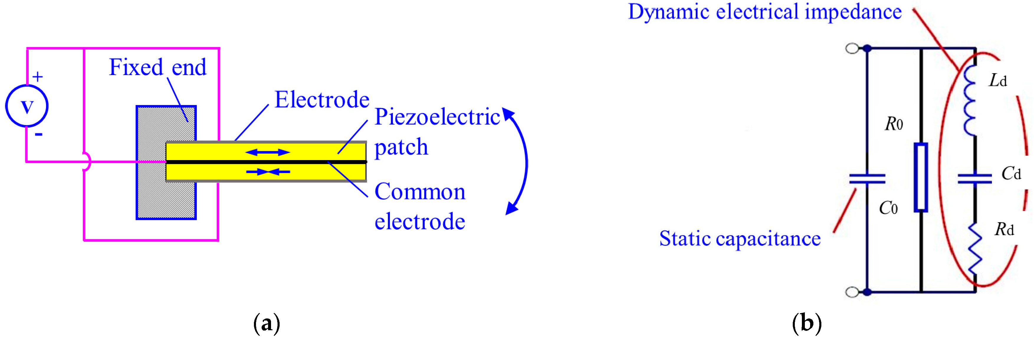
The structure of the commonly used piezoelectric bimorph beam is shown in
Figure 1a. This beam is composed of two piezoelectric patches with the same polarization directions and a common electrode in the middle. The two piezoelectric patches are wired, and alternating current (AC) voltage is applied (
Figure 1a). The driving electric fields applied to the plates are always opposite each other. The polarization directions of the two piezoelectric patches are the same; hence, one of the plates contracts, whereas the other expands. This condition causes the piezoelectric bimorph beam to bend and swing. The swing frequency corresponds to the applied alternating current frequency.
A piezoelectric bimorph beam is an electromechanical coupling device. Its equivalent circuit is shown in
Figure 1b [
16], where
C0 is the static capacitance,
R0 is the dielectric loss parallel resistance,
Rd is the dynamic resistance,
Cd is the parallel capacitance, and
Ld is the dynamic inductance. When the mechanical quality factor of a component is high,
Cd and
Ld can be considered constant within the range of a given resonance frequency. The value of
Rd is related to the mechanical energy of mechanical loss. The impedance of the circuit is simplified as its static admittance as
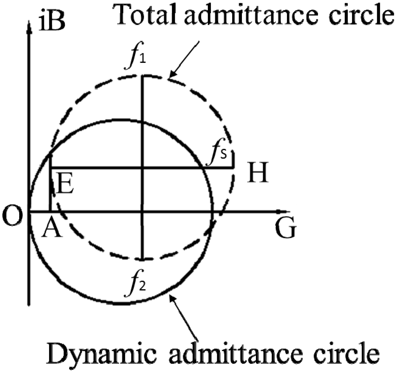
The solid and dotted lines of the dynamic admittance on the complex plane form a circle, which is called an admittance circle.
Similarly, the total admittance on the complex plane also forms an admittance circle.
The dynamic admittance circle and the total admittance circle are represented by solid and dotted lines, respectively, in
Figure 2.
The diagram of the admittance circle is used to identify all the parameters of the equivalent circuit of the piezoelectric bimorph beam. The diameter of the circle is set as D, then
A straight line (EH) is drawn parallel to the conductive axis that passes through the center of the circle. Then, the circle is intersected at point H. The frequency that corresponds to point H is the mechanical resonance frequency fs. Static capacitance and dielectric loss resistance can then be determined.
Using the corresponding distance
from
Figure 2, the static capacitance can be determined
Using the corresponding distance
from
Figure 2, the dielectric loss resistance can be determined
A straight line is drawn perpendicular to the conductive axis. The intersection frequencies are
f1 and
f2 [
17,
18,
19]. Then, using the corresponding distances and frequencies from
Figure 2, the dynamic inductance and parallel capacitance can be determined.
3. Methods for the Admittance Test of a Piezoelectric Bimorph Beam
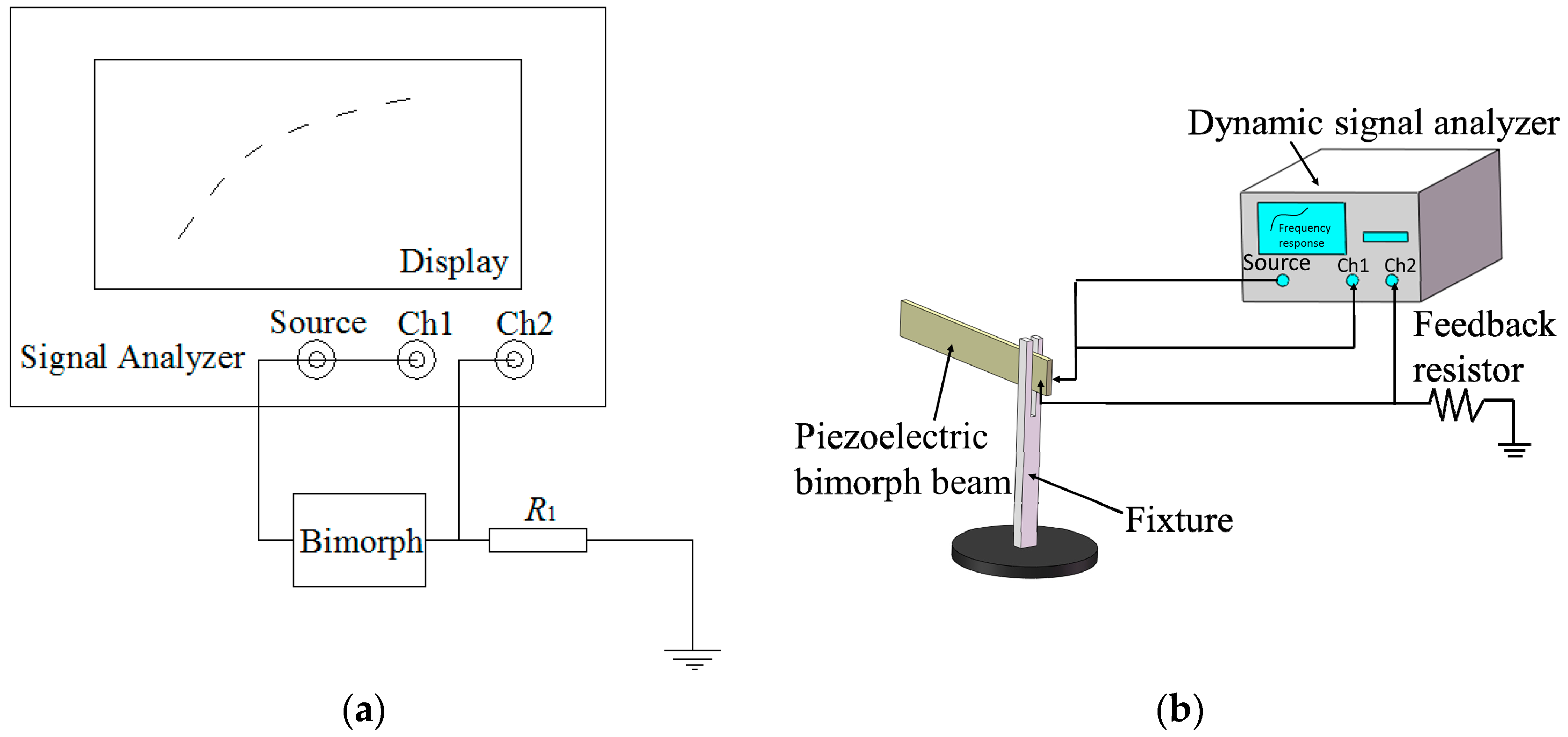
This study uses a dynamic signal analyzer to test the admittance spectrum of a piezoelectric bimorph beam based on the preceding theoretical analysis. The detection principle is illustrated in
Figure 3a. In the figure, the piezoelectric bimorph beam and feedback resistance
R1 (resistance value = 1 Ω; hence, the values of the passing voltage and current are equal) are in series connection: one end is connected to the ground, whereas the other end is connected to the signal source of the dynamic signal analyzer. The voltage value
U1 of the signal source and the voltage value
U2 of the feedback resistor are input into Channel 1 (Ch1) and Channel 2 (Ch2) of the analyzer, respectively. The function of the feedback resistor is to convert the current signal of the piezoelectric bimorph beam into a voltage signal for the input analyzer. The calculation function of the dynamic signal analyzer can be used to obtain the admittance
Yc(ω) (reverse of resistance) of the piezoelectric bimorph beam as
where
and
are the current and voltage of the piezoelectric bimorph beam, respectively; and
and
are the feedback resistor and voltage of the signal source, respectively.
As shown in
Figure 3b, the admittance test system for the piezoelectric bimorph beam comprises the piezoelectric bimorph beam, a fixture, a feedback resistor, and a dynamic signal analyzer (SR785, Stanford Research Systems, Inc., Sunnyvale, CA, USA). The piezoelectric bimorph beam is 50 mm long, 2 mm wide, and 0.7 mm thick. The fixture is used to clamp one end of the piezoelectric bimorph beam, and the cantilever beam is left with a length of 35 mm. The dynamic signal analyzer is used to apply excitation signals with different frequencies to the piezoelectric bimorph beam to measure the admittance value of the beam and obtain the admittance circle. Consequently, the resonant characteristics of the piezoelectric bimorph beam can be analyzed.
4. Experiment Result and Discussion of the Admittance Test
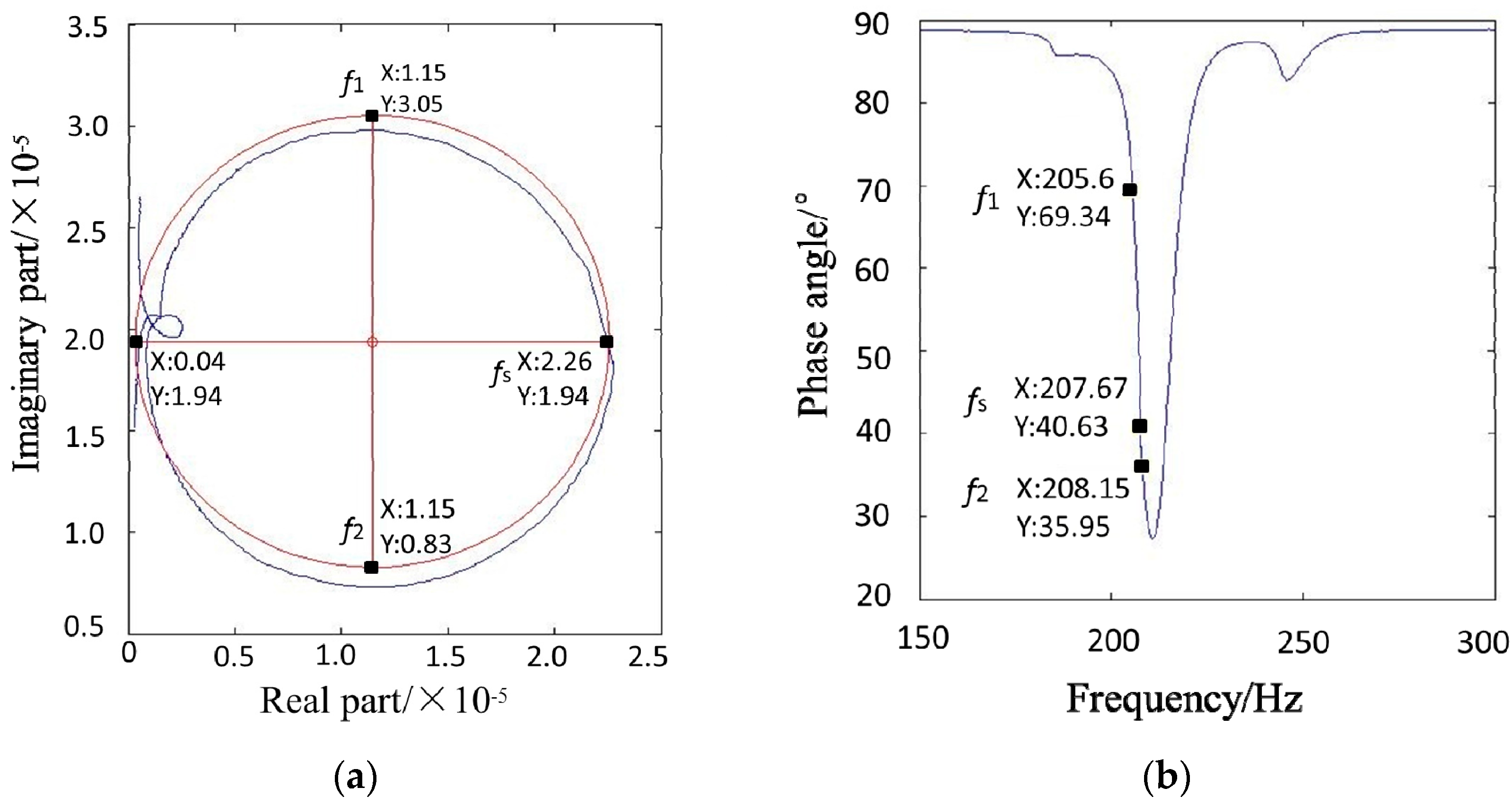
The admittance test system for the piezoelectric bimorph beam is used to measure the admittance circle curve (blue line in
Figure 4a) and the phase frequency characteristic curve (
Figure 4b). As shown in
Figure 4a, the measured admittance curve is not perfectly round due to various interference factors, such as interference curves. To determine the relevant parameters, this study uses the circular fitting method to make the fitted circle (red line in
Figure 4a) an approximation of the measured admittance circle through MATLAB software (R2010a, MathWorks, Inc., Natick, MA, USA). The specific method is described as follows [
20].
The center of the admittance circle is set as (−a/2, −b/2), the radius is r, and the equation of the circle is
That is,
Through the least squares method,
where (
xi,
yi) are the coordinates at a certain point on the measured admittance circle.
The center of the fitted admittance circle is (1.15 × 10
−5, 1.94 × 10
−5) and the radius is 1.11 × 10
−5 m, which can determine the coordinates of the frequency points of the piezoelectric bimorph beam on the admittance circle curve (
Figure 4a), the resonant frequency point
fs (2.26 × 10
−5, 1.94 × 10
−5), and the two auxiliary frequency points, i.e.,
f1 (1.15 × 10
−5, 3.05 × 10
−5) and
f2 (1.15 × 10
−5, 8.3 × 10
−6). The coordinates of each frequency point are used to obtain their phase angle
θ according to the formula
θ = arctan(
Y/
X). The frequency region of the phase angle in the phase frequency characteristic curve is observed. Then, MATLAB software is used to search for the coordinates of each frequency point in the phase frequency characteristic curve (
Figure 4b), the resonant frequency point
fs (207.67, 40.63), the auxiliary frequency point
f1 (205.60, 69.34), and the auxiliary frequency point
f2 (208.15, 35.95) is obtained. Therefore, the resonant frequency point
fs = 207.67 Hz and the auxiliary frequency points
f1 = 205.60 Hz,
f2 = 208.15 Hz are determined.
Subsequently, all the parameters in the equivalent circuit of the piezoelectric bimorph beam are obtained as
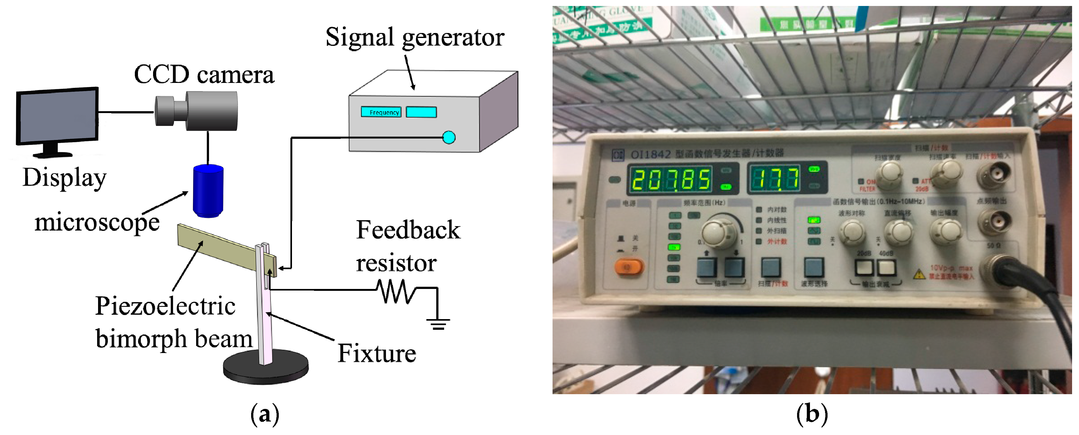
To verify the feasibility and accuracy of the admittance test result, the microscope image observation method is used to retest the resonant frequency of the piezoelectric bimorph beam. A system diagram of the microscope image observation method is shown in
Figure 5a. The system includes the piezoelectric bimorph beam, a fixture, a signal generator (OI1842, Beijing Ocean Xingye Technology Co., Ltd., Beijing, China), and a probe system (M150, Cascade Microtech, Inc., Beaverton, OR, USA); and the probe system contains a microscope, a charge-coupled device (CCD) camera, and a display. The principle of the test is described as follows. When the signal generator provides electrical signals to the piezoelectric bimorph beam, the beam begins to vibrate. The vibration of the beam is observed through the microscope and the CCD camera. The piezoelectric bimorph beam is in a resonant state when the frequency of the electrical signals supplied to it is equal to its resonant frequency. The amplitude of the piezoelectric bimorph beam observed on the display is highest during that time, and the excitation signal frequency displayed on the signal generator is the resonant frequency of the beam.
To ensure the accuracy of the test experiment, we use the same clamping method applied to the admittance test—i.e., the fixture is used to clamp one end of the piezoelectric bimorph beam—while leaving the cantilever beam with a length of 35 mm. Thereafter, the signal generator is used to apply excitation signals with different frequencies to the piezoelectric bimorph beam. The vibration of the piezoelectric bimorph beam is observed on the display.
The value of the signal generator is shown in
Figure 5b when the amplitude of the piezoelectric bimorph beam is at its highest during the experiment. The piezoelectric bimorph beam is in a resonant state when the electrical signal is 207.85 Hz. Therefore, the resonant frequency is 207.85 Hz, which is basically consistent with the resonant frequency of 207.67 Hz obtained through the admittance circle. This result proves the feasibility and accuracy of applying the admittance circle to analyze the dynamic characteristics of a piezoelectric bimorph beam.
Moreover, the resonant frequencies of the piezoelectric bimorph beam can be theoretically calculated. We have calculated the resonant frequency of the piezoelectric bimorph beam as 222.03 Hz, when compared to the resonant frequencies obtained from the experiments, the differences are less than 8%, and the differences may be caused by the measurement errors, including measure of the cantilever beam size, the clamping position of the cantilever beam, and so on. Therefore, the theoretically calculated result can also prove the feasibility and accuracy of applying the admittance circle to analyze the dynamic characteristics of a piezoelectric bimorph beam.
