1. Introduction
Compliant mechanisms have no traditional sliding or rolling hinges, thereby lending advantages over rigid-body counterparts, such as no backlash, no requirement for lubrication, simplified manufacture, and low part count [
1,
2,
3,
4,
5,
6,
7,
8]. Currently, XYZ compliant parallel mechanisms (XYZ CPMs) are gaining more and more attention and are being widely employed in a variety of applications such as atomic force microscopy (AFM), micro-/nano-manipulation, high precision alignment, and microelectromechanical systems (MEMS) processes [
6,
9,
10,
11,
12,
13,
14,
15,
16].
In most of the above applications, an XYZ CPM acts as a type of macro-scale mechatronic motion system, and its output motion stage (MS) should be capable of translating along the X-, Y- and Z-axes, with ultra-high precision [
17]. However, compliant joints in an XYZ CPM are not ideal compared with their rigid-body counterparts. The stiffness of a compliant joint is neither zero in the degree of freedom (DOF) directions nor infinitely large in the degree of constraint (DOC) directions. Hence, an XYZ CPM often suffers from undesired parasitic motions and coupling motions [
9,
10]. For the MS of an XYZ CPM as an example, the parasitic motions are the three rotations of the MS about the X-, Y- and Z-axes, which should be much smaller than its three primary translations.
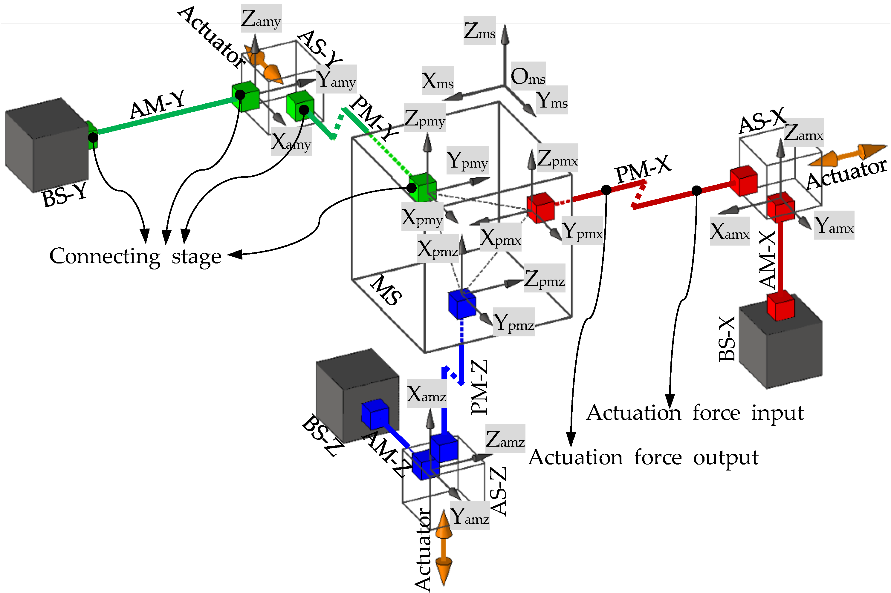
An XYZ CPM is always actuated by three translational actuators, such as voice coils and piezoelectric stacks, exerted on the three actuated stages (ASs: AS-X, AS-Y and AS-Z along the three axes) [
5,
18]. As is well known, translational actuators cannot tolerate off-axis loads or displacements. Therefore, an AS is permitted to translate only along the actuation direction [
9,
18], the motions along and about the other directions are the parasitic motions of the AS. In order to protect the three translational actuators and achieve precise control in an XYZ CPM system, the parasitic rotations and the parasitic translations of the three ASs should be minimized.
The three desired translations of the MS and the one permitted translation of each AS in an XYZ CPM system are the primary translations of the XYZ CPM. Based on [
9,
11], the primary translations of an XYZ CPM should have the following desired characteristics: (a) reduced cross-axis coupling: the primary translation of an MS along one axis should be independent from the primary actuation along the other two axes; and (b) minimized lost motion: in the X-, Y- or Z-axis direction, the motion reduction between the primary translations of the AS and the MS should be minimized. All XYZ CPMs desire the above two primary translation characteristics, especially when closed-loop control systems are not available. The cross-axis coupling of an XYZ CPM can be measured by three cross-axis coupling rates regarding the three primary translations of the MS. When only one axis actuation is applied on an XYZ CPM, the primary translation of the MS along this axis is defined as the nominal primary translation of the MS along the axis. The primary translation of the MS will deviate from the nominal primary translation, if the other one or two actuations are applied. The ratio of the deviation to the nominal primary translation is termed the cross-axis coupling rate along this axis. The lost motions of an XYZ CPM, along the X-, Y- or Z-axes, can be represented as three lost motion rates. The lost motion rate along one axis is defined as the ratio of the motion reduction to the AS’s primary translation along the axis.
As a result, the following attributes, Cross-Axis Coupling Rates, Lost Motion Rates, Parasitic Rotations and Parasitic Translations, can be used to measure the motion performance of an XYZ CPM. This paper defines the motions of an XYZ CPM as follows: MS’s motions along and about the X-, Y- and Z-axes of the global coordinate system are ξ
ms-tx, ξ
ms-ty, ξ
ms-tz, ξ
ms-rx, ξ
ms-ry and ξ
ms-rz; AS-X’s motions along and about the X-, Y- and Z-axes of the AS-X’s local coordinate system are ξ
asx-tx, ξ
asx-ty, ξ
asx-tz, ξ
asx-rx, ξ
asx-ry and ξ
asx-rz; AS-Y’s motions along and about the X-, Y- and Z-axes of the AS-Y’s local coordinate system are ξ
asy-tx, ξ
asy-ty, ξ
asy-tz, ξ
asy-rx, ξ
asy-ry and ξ
asy-rz; AS-Z’s motions along and about the X-, Y- and Z-axes of the AS-Z’s local coordinate system are ξ
asz-tx, ξ
asz-ty, ξ
asz-tz, ξ
asz-rx, ξ
asz-ry and ξ
asz-rz. Note that the
X-axes of the AS-X’s, AS-Y’s and AS-Z’s local coordinate systems parallel to the X-, Y- and Z-axes of the global coordinate system, respectively. Therefore, the above four attributes of an XYZ CPM can be represented or calculated, as shown in
Table 1. For a desired XYZ CPM, the above four attributes should be minimized. In addition, compact configuration and easy fabrication are also preferable [
6].
Table 1.
Representation or calculation of the four motion characteristics of an XYZ CPM.
Table 1.
Representation or calculation of the four motion characteristics of an XYZ CPM.
| Motion Characteristics | X-Axis | Y-Axis | Z-Axis |
|---|
| Cross-Axis Coupling Rates | |(ξms-tx − ξms-tx°)/ξms-tx°| | |(ξms-ty − ξms-ty°)/ξms-ty°| | |(ξms-tz − ξms-tz°)/ξms-tz°| |
| Lost Motion Rates | (ξasx-tx − ξms-tx)/ξasx-tx | (ξasy-tx − ξms-ty)/ξasy-tx | (ξasz-tx − ξms-tx)/ξasz-tx |
| Parasitic Rotations | ξms-rx, ξms-ry, ξms-rz, ξasx-rx, ξasx-ry, ξasx-rz, ξasy-rx, ξasy-ry, ξasy-rz, ξasz-rx, ξasz-ry, ξasz-rz |
| Parasitic Translations | ξasx-ty, ξasx-tz, ξasy-ty, ξasy-tz, ξasz-ty, ξasz-tz |
In recent years, many XYZ CPMs [
6,
9,
10,
11,
12,
18,
19,
20] have been designed using the pseudo-rigid-body-based model substitution approach [
21], the constraint-based approach [
22,
23], the screw-theory-based approach [
24], the freedom and constraint topology approach [
25,
26], and the CPI approach [
18]. These existing XYZ CPMs have one or some of the four desired performance characteristics mentioned above. For example, the XYZ CPMs demonstrated in [
6,
9,
10,
11,
12,
18,
20] have small cross-axis coupling attributes, and the XYZ CPM reported in [
11] also has relative small parasitic rotations. However, none of the reported XYZ CPMs have all the four desired motion characteristics, because the design of such an XYZ CPM is still challenging.
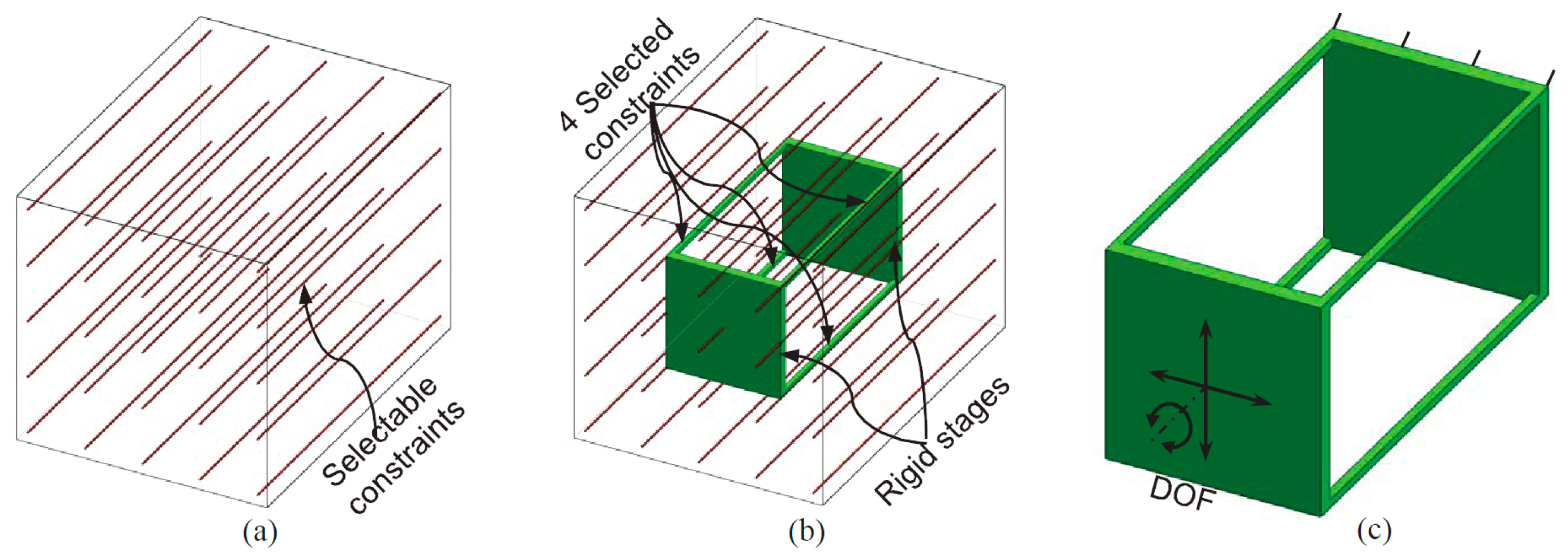
This paper proposes a new XYZ CPM whose cross-axis coupling rates, lost motion rates, parasitic rotations and parasitic translations are minimized. The proposed XYZ CPM is synthesized using the CPI approach [
18] with certain configuration modification, such as adding rigid linkages between some non-adjacent rigid stages [
27,
28]. The good motion characteristics of the designed XYZ CPM are validated by the finite element analysis (FEA) results. Moreover, the primary translations of the XYZ CPM are also nonlinearly modeled in an analytical form, which can offer quick quantitative and parametric insights into the actuation stiffness and the force-displacement relationship.
The remainder of this paper is organized as follows.
Section 2 reviews the CPI approach of synthesizing XYZ CPMs. An XYZ CPM, in
Section 3, is proposed based on the CPI approach. The kinematic analysis is carried out based on a series of FEA simulations in
Section 4. The nonlinear analytical models of the primary translations are obtained and validated in
Section 5. Furthermore,
Section 6 shows two practical designs of the proposed XYZ CPM, and
Section 7 introduces a spatial high-precision translational system designed based on practical designs. Finally, conclusions are drawn in
Section 8.
4. FEA-Result-Based Kinematic Analysis
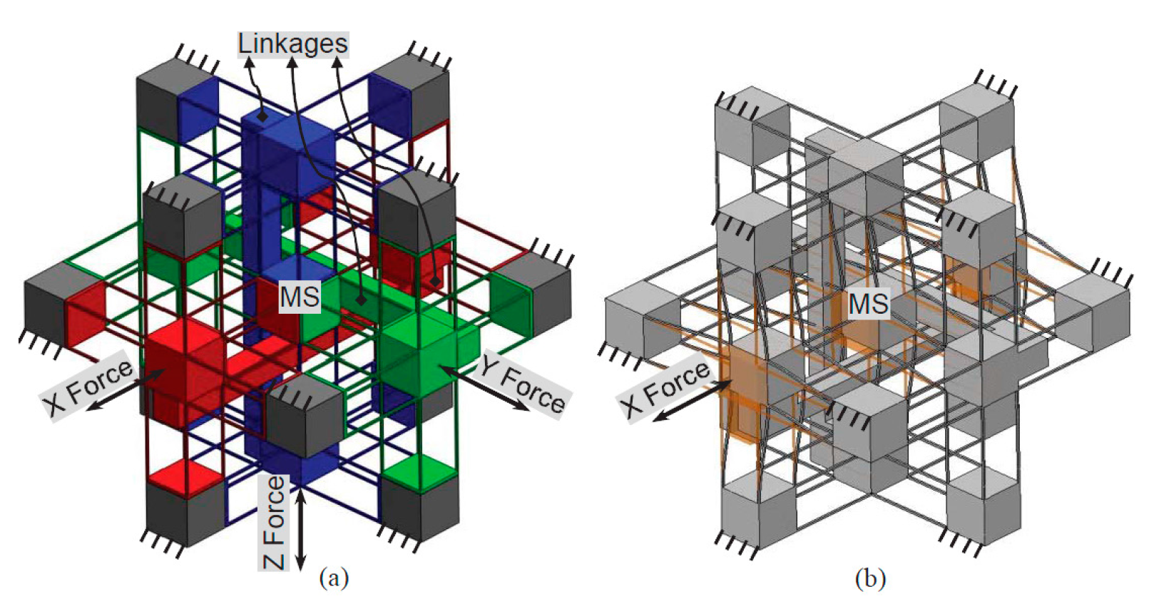
In this section, the motion characteristics, including the cross-axis coupling rates, the lost motion rates, the parasitic rotations and the parasitic translations of the XYZ CPM are analyzed based on the FEA results. And the relations between the motion characteristics and the geometric parameters are studied. In addition, the comparison between the two XYZ CPMs with and without the rigid linkages, as shown in
Figure 5 and
Figure 6, is also carried out.
The designed XYZ CPM, as shown in
Figure 6, has an isotropic configuration (all the wire beams of the XYZ CPM are identical in dimension and material), so only the motion characteristics associated with one of the three orthogonal directions needs to be analyzed. In this paper, the motion characteristics associated with the X-axis translation is studied. The rotational stiffness of the ASs is larger than those of the MS, due to introducing the three rigid linkages. So the parasitic rotations of the ASs should not be larger than the parasitic rotations of the MS. Therefore, the parasitic rotations of the ASs are not analyzed in this case. As a result, only the primary translations of the MS and the AS-X, the parasitic rotations of the MS, and the parasitic translations of the AS-X are studied in this case. Additionally, in this paper, the displacements and lengths are normalized by the beam length
L, the translational forces are normalized by
EI/
L2, and the rotational forces are normalized by
EI/
L, where
E is the Young’s modulus of the material, and
I is the second moment of area of the beam [
29].
For the FEA model, assume that
E = 69,000 MPa,
υ = 0.33, and the normalized motion range per axis is limited to ±5%
L which can be considered as a medium-large motion range compared with the beam length [
29]. Moreover, the commercial software, COMSOL MULTIPHYSICS (COMSOL Group, Stockholm, Sweden), is selected for the nonlinear FEA simulations, using the 10-node tetrahedral element and fine meshing technology. In addition, the three actuations are applied on the surface centers of the three cubic ASs, respectively, as shown in
Figure 6. Additionally, each of the three actuation points is the motion reference point of the AS in the FEA simulations, whose motion is regarded as the motion of the AS. Similarly, the center point of the cubic MS is defined as the motion reference point of the MS.
The main geometric parameters of the XYZ CPM are the beam length L, the beam thickness T and the width W of the identical cubes, which can be analyzed in the following two dimensionless parameters: beam’s slenderness ratio λb (in this paper, λb = L/T) and the ratio, w, of the W to the L (w is actually the normalized width of the identical cubes, which equals to W/L). In order to estimate the effects of the two dimensionless parameters on the motion characteristics, a series of values are selected for the two dimensionless parameters, λb and w, in the FEA model.
In order to achieve a several-millimeter motion range, the beam length L should be up to dozens of millimeters (as mentioned above, the motion range per axis equals to ±5%L). So it is appropriate to select 20, 30, 40, 50, 60, 70, 80, 90 and 100 mm as the beam length, respectively. For these beam lengths, 1 mm beam thickness and 20 mm width are appropriate. Based on the above selected dimension, λb varies from 20 to 100. For each of the values of λb, FEA simulation is carried out, under the following actuation condition: The normalized X-axis actuation displacement, ξasx-tx, varies from −0.05 to +0.05, and the other two normalized actuation displacements, ξasy-tx and ξasz-tx, are both 0.05. In this actuation condition, the cross-axis coupling rate regarding the MS’s X-axis translation, the lost motion rate along the X-axis, the parasitic rotations of the MS about the Y- and Z-axes, and the parasitic translations of the AS-X along the Y- and Z-axes can reach their maximum values.
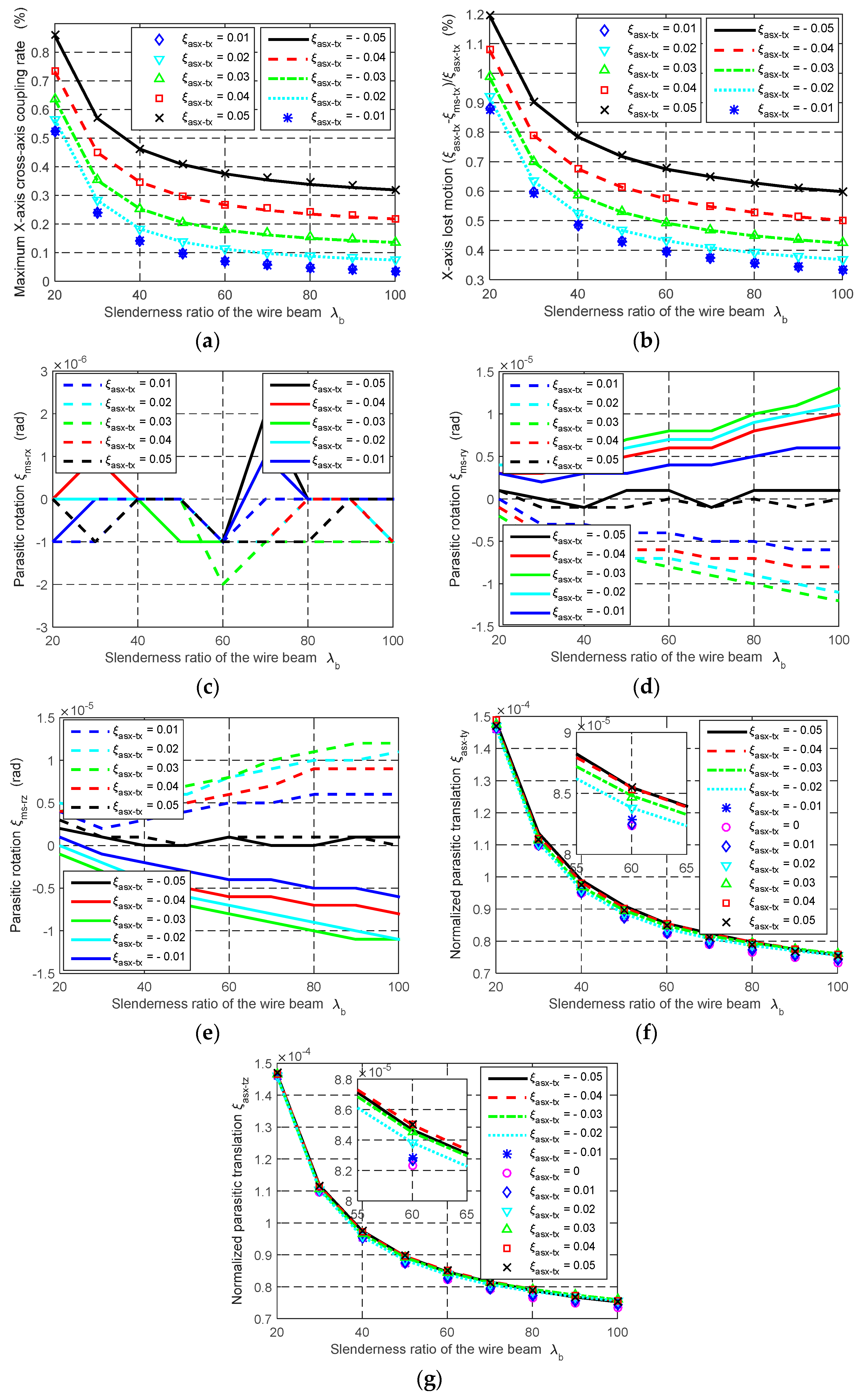
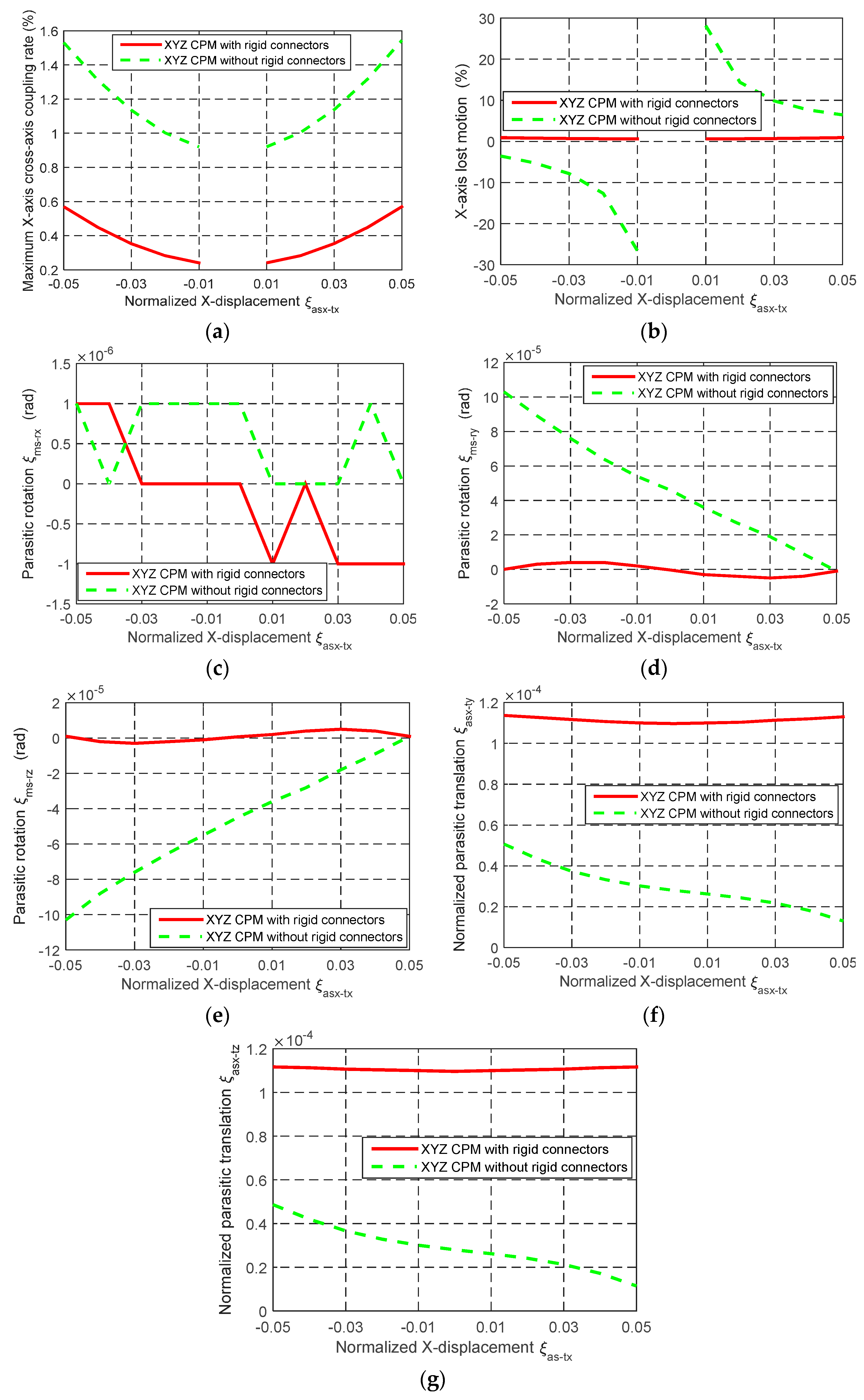
The FEA results are shown in
Figure 7. With λ
b changing from 20 to 100, it can be seen that: (a) the maximum cross-axis coupling rate, in terms of the MS’s X-axis translation, reduces from 0.86% to 0.32%, as shown in
Figure 7a; (b) the maximum X-axis lost motion rate varies from 1.20% to 0.60%, as shown in
Figure 7b; (c) the parasitic rotation of the MS about the X-axis shows a highly discontinuous behavior responding to the slenderness ratio conditions, which are in the order of 10
−6 rad, as shown in
Figure 7c; (d) the maximum parasitic rotation of the MS about the Y- or Z-axis increases slightly, but is still in the order of 10
−5, as shown in
Figure 7d,e; and (e) the normalized parasitic translations of the AS-X along the Y- and Z-axes decrease from about 1.5 × 10
−4 to 0.76 × 10
−4, as shown in
Figure 7f,g. In the condition of increasing the value of λ
b, the FEA results reveal that the cross-axis coupling rate, the lost motion rate and the parasitic translations decrease, but the parasitic rotations increase slightly. It can also be seen that the obtained cross-axis coupling rate, lost motion rate, parasitic rotations and parasitic translations are reduced compared with the XYZ CPM proposed in [
9], for all the values of λ
b.
Compared with the effect of λ
b under the same actuation condition, the effect of
w on the motion characteristics of the XYZ CPM is negligible, which can be seen from the FEA results shown in
Table 3 (when
L = 30 mm). Particularly, the cross-axis coupling rate and the lost motion rate do not change, when the
w are assigned 1/3, 2/3 and 1, respectively. The parasitic rotations decrease slightly when increasing the
w value.
The comparison of the motion characteristics of the two XYZ CPMs with and without the rigid linkages, as shown in
Figure 5 and
Figure 6, is also conducted in this section. When
λb = 30 and
w = 2/3, the comparison of the motion characteristics of the two XYZ CPMs is demonstrated in
Figure 8. The FEA results illustrate that: (a) the cross-axis coupling rate, the lost motion rate and the parasitic rotations of the XYZ CPM with the rigid linkages are much smaller than corresponding ones of the XYZ CPM without the rigid linkages, respectively; and (b) the AS-X of the XYZ CPM with the rigid linkages has slightly larger normalized parasitic translations, which are, however, in the order of 10
−4 and less than 0.23% of the primary translation of the AS-X. For any one of the two XYZ CPMs with and without the rigid linkages, the parasitic translations of the AS-X along the Y- and Z-axes mainly arise from the actuation forces along the Y- and Z-axes, respectively. The parasitic translations of the AS-X of the XYZ CPM without the rigid linkages along the Y- and Z-axes are slightly smaller than those of the XYZ CPM with the rigid linkages, probably because, for a certain displacement of the AS-X, the XYZ CPM without the rigid linkages needs a smaller actuation force along the X-axis.
Table 3.
The variation of the motion characteristics of the XYZ CPM with the rigid-cube width w.
Table 3.
The variation of the motion characteristics of the XYZ CPM with the rigid-cube width w.
| AS-X X-Translation, ξasx-tx | −0.05 | −0.03 | −0.01 | 0.01 | 0.03 | 0.05 |
|---|
| Cross-axis coupling rate (%) | w = 1/3 | 0.57 | 0.35 | 0.24 | 0.24 | 0.35 | 0.57 |
| w = 2/3 | 0.57 | 0.35 | 0.24 | 0.24 | 0.35 | 0.57 |
| w = 1 | 0.57 | 0.35 | 0.24 | 0.24 | 0.35 | 0.57 |
| Lost motion rate (%) | w = 1/3 | 0.90 | 0.70 | 0.59 | 0.59 | 0.70 | 0.90 |
| w = 2/3 | 0.90 | 0.70 | 0.59 | 0.60 | 0.70 | 0.90 |
| w = 1 | 0.90 | 0.70 | 0.59 | 0.60 | 0.70 | 0.90 |
| MS X-rotation, ξms-rx, (rad) | w = 1/3 | 0.00 × 100 | 0.00 × 100 | −1.00 × 10⁻⁶ | −1.00 × 10⁻⁶ | 0.00 × 100 | −1.00 × 10⁻⁶ |
| w = 2/3 | 1.00 × 10⁻⁶ | 0.00 × 100 | 0.00 × 100 | −1.00 × 10⁻⁶ | −1.00 × 10⁻⁶ | −1.00 × 10⁻⁶ |
| w = 1 | −3.00 × 10⁻⁶ | −2.00 × 10⁻⁶ | −1.00 × 10⁻⁶ | −1.00 × 10⁻⁶ | −1.00 × 10⁻⁶ | −1.00 × 10⁻⁶ |
| MS Y-rotation, ξms-ry, (rad) | w = 1/3 | 0.00 × 100 | 6.00 × 10⁻⁶ | 3.00 × 10⁻⁶ | −3.00 × 10⁻⁶ | −6.00 × 10⁻⁶ | 0.00 × 100 |
| w = 2/3 | 0.00 × 100 | 4.00 × 10⁻⁶ | 2.00 × 10⁻⁶ | −3.00 × 10⁻⁶ | −5.00 × 10⁻⁶ | −1.00 × 10⁻⁶ |
| w = 1 | 0.00 × 100 | 4.00 × 10⁻⁶ | 2.00 × 10⁻⁶ | −1.00 × 10⁻⁶ | −2.00 × 10⁻⁶ | 2.00 × 10⁻⁶ |
| MS Z-rotation, ξms-rz, (rad) | w = 1/3 | 0.00 × 100 | −5.00 × 10⁻⁶ | −3.00 × 10⁻⁶ | 3.00 × 10⁻⁶ | 5.00 × 10⁻⁶ | 0.00 × 100 |
| w = 2/3 | 1.00 × 10⁻⁶ | −3.00 × 10⁻⁶ | −1.00 × 10⁻⁶ | 2.00 × 10⁻⁶ | 5.00 × 10⁻⁶ | 1.00 × 10⁻⁶ |
| w = 1 | 1.00 × 10⁻⁶ | −4.00 × 10⁻⁶ | −2.00 × 10⁻⁶ | 1.00 × 10⁻⁶ | 3.00 × 10⁻⁶ | 0.00 × 10° |
| AS-X Y-translation, ξasx-ty | w = 1/3 | 1.12 × 10⁻⁴ | 1.11 × 10⁻⁴ | 1.09 × 10⁻⁴ | 1.09 × 10⁻⁴ | 1.10 × 10⁻⁴ | 1.11 × 10⁻⁴ |
| w = 2/3 | 1.14 × 10⁻⁴ | 1.12 × 10⁻⁴ | 1.10 × 10⁻⁴ | 1.10 × 10⁻⁴ | 1.11 × 10⁻⁴ | 1.13 × 10⁻⁴ |
| w = 1 | 1.11 × 10⁻⁴ | 1.10 × 10⁻⁴ | 1.09 × 10⁻⁴ | 1.09 × 10⁻⁴ | 1.10 × 10⁻⁴ | 1.11 × 10⁻⁴ |
| AS-X Z-translation, ξasx-tz | w = 1/3 | 1.12 × 10⁻⁴ | 1.11 × 10⁻⁴ | 1.10 × 10⁻⁴ | 1.10 × 10⁻⁴ | 1.11 × 10⁻⁴ | 1.12 × 10⁻⁴ |
| w = 2/3 | 1.12 × 10⁻⁴ | 1.11 × 10⁻⁴ | 1.10 × 10⁻⁴ | 1.10 × 10⁻⁴ | 1.11 × 10⁻⁴ | 1.12 × 10⁻⁴ |
| w = 1 | 1.11 × 10⁻⁴ | 1.10 × 10⁻⁴ | 1.09 × 10⁻⁴ | 1.09 × 10⁻⁴ | 1.10 × 10⁻⁴ | 1.11 × 10⁻⁴ |
Figure 7.
The variation of the motion characteristics of the XYZ CPM with the beam slenderness ratios λb: (a) Cross-axis coupling rate in terms of the X-axis primary translation of the MS, (b) lost motion rate along the X-axis, (c–e) parasitic rotations of the MS about the X-, Y- and Z-axes, respectively and (f–g) parasitic translations of the AS along the Y- and Z-axes, respectively.
Figure 8.
The comparison of the motion characteristics of the two XYZ CPMs with and without the rigid linkages, as shown in
Figure 5 and
Figure 6, respectively: (
a) Cross-axis coupling rate in terms of the X-axis primary translation of the MS, (
b) lost motion rate along the X-axis, (
c–
e) parasitic rotations of the MS about the X-, Y- and Z-axes; respectively and (
f–
g) parasitic translations of the AS along the Y- and Z-axes, respectively.
5. Analytical Modeling
The motion characteristics of the XYZ CPM, as shown in
Figure 6, are predicted based on the FEA results, and the relations between the motion characteristics and the main geometric parameters are studied as well. In this section, the nonlinear analytical model of the XYZ CPM is derived, which can be used to predict the force-displacement relationship, and to estimate the actuation stiffness, before conducting FEA simulations and experimental tests. As observed in
Section 4, the parasitic rotations and the parasitic translations are much smaller than the primary translations. Therefore, it is appropriate to ignore the effects of the parasitic motion on the analytical models of the primary translations.
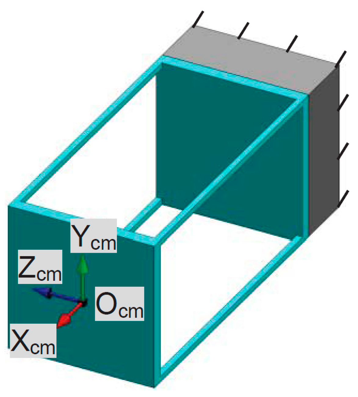
Each PM of the XYZ CPM can be referred to as a four-beam compliant module (FBCM) as shown in
Figure 9, and each AM of the XYZ CPM can be regarded as the parallel combination of four FBCMs. Therefore, the motions of the XYZ CPM are performed through the deformation of the FBCMs in the XYZ CPM, so the modeling of the FBCM is carried out before modeling the complete XYZ CPM.
Figure 9.
An FBCM and its coordinate system.
Figure 9.
An FBCM and its coordinate system.
The analytical model of the FBCM can be found in [
30,
31], which can be rewritten as Equations (1)–(3).
where
t is normalized thickness of the beam. ξ
cm-tx, ξ
cm-ty and ξ
cm-tz are the translational displacements of the FBCM’s output stage along the X
cm-, Y
cm- and Z
cm-axes, respectively. ζ
cm-tx, ζ
cm-ty and ζ
cm-tz are the reaction forces along the X
cm-, Y
cm- and Z
cm-axes, respectively, which are produced by the FBCM due to the deformation of the beams in the FBCM. Note that the rotations of the FBCM about the X
cm-, Y
cm- and Z
cm-axes are not taken into account, because the rotations of the FBCM in the XYZ CPM system are negligible compared with the translations, as analyzed in
Section 4.
According to the analytical model, an FBCM can be regarded as a three-dimension translational spring. The complete XYZ CPM can be modeled based on the analytical model of the three-dimension translational spring. As already mentioned, the motion performance of the XYZ CPM along the X
ms-, Y
ms- and Z
ms-axes are identical (O
ms-X
msY
msZ
ms are the global coordinate system in this section). Therefore, only the primary translations along one of the three directions need to be studied. In this paper, the derivation of the force-displacement relationship, associated with only the translations along the X
ms-axis, is detailed. Given any displacements, ξ
asy-tx and ξ
asz-tx, of the AS-Y and AS-Z, respectively, the XYZ CPM can be simplified to the model shown in
Figure 10 if only the force-displacement relationship in X
m-axis is concerned.
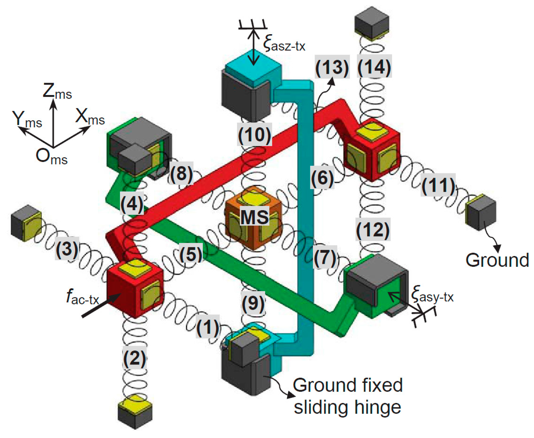
Figure 10.
Demonstration of the rigid stages and FBCMs in the XYZ CPM system associated with only the Xms-axis translation (AS-Xs and their rigid linkage are red in color, AS-Ys and their rigid linkage are green in color, and AS-Zs and their rigid linkage are blue in color).
Figure 10.
Demonstration of the rigid stages and FBCMs in the XYZ CPM system associated with only the Xms-axis translation (AS-Xs and their rigid linkage are red in color, AS-Ys and their rigid linkage are green in color, and AS-Zs and their rigid linkage are blue in color).
Assume that the lost motions along the X
ms-, Y
ms- and Z
ms-axes are δ
x, δ
y and δ
z, respectively, which can be written as shown in Equation (4).
where ξ
ms-tx, ξ
ms-ty, ξ
ms-tz, ξ
asx-tx, ξ
asy-tx and ξ
asz-tx are the primary translations of the MS and ASs, as defined in
Section 1. The model, as shown in
Figure 10, contains 14 FBCMs, which are termed as FBCM-1 to FBCM-14, respectively. If all the parasitic rotations and parasitic translations of the XYZ CPM are ignored, the deformation displacements of each of the FBCMs can be obtained easily according to the primary translations and lost motions. Additionally, the reaction forces of the FBCMs can also be calculated based on Equation (1). Taking the FBCM-1 as an example, the FBCM-1 is linked to the AS-X, so the deformation displacements of the FBCM-1 can be derived from the motion displacements of the AS-X. If ignoring all the parasitic rotations and parasitic translations of the AS-X, the deformation displacements of the FBCM-1 equal to ξ
asx-tx, zero and zero along the X
ms-, Y
ms- and Z
ms-axes, respectively. Therefore, the reaction force, ζ
a, of the FBCM-1 along the X
ms-axis can be obtained, as shown in Equation (5), via substituting the deformation displacements of the FBCM-1 into Equations (2) or (3). Note that when substituting the deformation displacements into Equation (2), ξ
cm-tx, ξ
cm-ty and ξ
cm-tz in Equation (2) equal to zero, ξ
asx-tx and zero, respectively; when substituting the deformation displacements into Equation (3), ξ
cm-tx, ξ
cm-ty and ξ
cm-tz in Equation (3) equal to zero, zero and ξ
asx-tx, respectively. Similarly, the reaction force of the FBCM-2, FBCM-3, FBCM-4, FBCM-11, FBCM-12, FBCM-13 or FBCM-14, to the AS-X along the X
ms-axis, can also be obtained as shown in Equation (5). Additionally, the reaction forces of the FBCM-5, FBCM-6, FBCM-7, FBCM-8, FBCM-9 and FBCM-10, to the MS along the X
ms-axis, can be derived in Equations (6)–(11), respectively, which are represented as ζ
b, ζ
c, ζ
d, ζ
e, ζ
f and ζ
g.
When the MS is at static equilibrium, all the reaction forces on the MS along the X
ms-axis should be balanced, so Equation (12) can be obtained. Substituting Equations (6)–(11) into Equation (12), Equation (13) can be derived. Furthermore, the actuation force,
fac-tx, should equal to the sum of the reaction forces of all the FBCMs except FBCM-5 and FBCM-6, along the X
ms-axis. Therefore, the relationship between the actuation force
fac-tx and the primary translations of the MS can be obtained, as shown in Equation (14).
Similarly, the lost motions along the Y
ms- and Z
ms-axes and the force-displacement relationships associated with the actuation forces,
fac-ty and
fac-tz, can be derived as shown in Equations (15)–(18). Note that the actuation forces,
fac-ty and
fac-tz, are applied on the AS-Y and AS-Z, respectively.
Based on Equations (14)–(18), the actuation forces, fac-tx, fac-ty and fac-tz, and the lost motions, δx, δy and δz, can be obtained when specific translational displacements of the MS, ξms-tx, ξms-ty and ξms-tz, are required. Furthermore, the primary translational displacements of the ASs, ξasx-tx, ξasy-tx and ξasz-tx, can also be obtained according to Equation (4).
The derived analytical models of the primary translations of the MS and ASs are applicable for any geometric dimension and material. When
L = 30 mm,
W = 20 mm,
T = 1 mm,
E = 69,000 MPa and
υ = 0.33, the analytical and FEA results of the X
ms-axis actuation force and the X
ms-axis lost motion, can be seen in
Figure 11 and
Figure 12 under the following three actuation conditions: (a) ξ
asx-tx varies from −0.05 to +0.05, ξ
asy-tx = 0 and ξ
asz-tx = 0; (b) ξ
asx-tx varies from −0.05 to +0.05, ξ
asy-tx = 0.05 and ξ
asz-tx = 0; and (c) ξ
asx-tx varies from −0.05 to +0.05, ξ
asy-tx = 0.05 and ξ
asz-tx = 0.05.
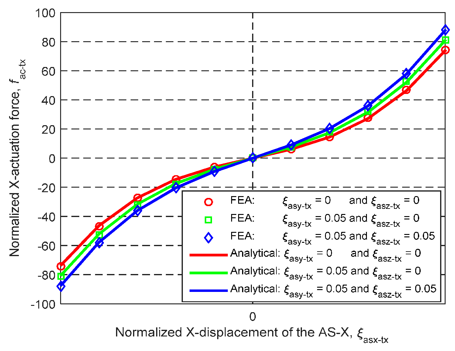
Figure 11 shows that the analytical results and the FEA results of the X
ms-axis actuation force match very well, with less than 2% difference.
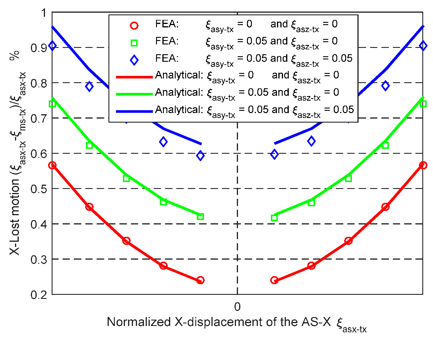
Figure 12 illustrates that the maximum difference between the analytical results and the FEA results of the X
ms-axis lost motion rate is less than 5.8%. It can be predicted that the analytical model of the MS’s primary translations should match the FEA model as well, according to Equation (4).
As studied in
Section 4, the cross-axis coupling rate and the lost motion rate of the XYZ CPM along the X
ms-axis are less than 0.38% and 0.68%, respectively, when λ
b = 60 and
w = 1/3. Therefore, along one axis, the primary translations of the MS and the AS are almost decoupled from the primary translations of the MS and the ASs along the other two axes. However, the X
ms-axis actuation forces, when ξ
asy-tx ≠ 0 and ξ
asz-tx ≠ 0, slightly deviate from the X
ms-axis actuation force when ξ
asy-tx = 0 and ξ
asz-tx = 0, as shown in
Figure 11. The deviation does not arise from the cross-axis coupling, but from the increase of the actuation stiffness along the X
ms-axis due to the exerted actuation displacements, ξ
asy-tx and ξ
asz-tx, along the Y
ms- and Z
ms-axes. The actuation stiffness along the three axes can be predicted by the derived analytical models, and the actuators can be selected based on the actuation stiffness.
Figure 11.
Analytical result and FEA result comparison regarding the relationship between the normalized Xms-axis primary translation of the AS-X and the normalized Xms-axis actuation force under the different conditions.
Figure 11.
Analytical result and FEA result comparison regarding the relationship between the normalized Xms-axis primary translation of the AS-X and the normalized Xms-axis actuation force under the different conditions.
Figure 12.
Analytical result and FEA result comparison regarding the relationship between the normalized Xms-axis primary translation of the AS-X and the Xms-axis lost motion under the different conditions.
Figure 12.
Analytical result and FEA result comparison regarding the relationship between the normalized Xms-axis primary translation of the AS-X and the Xms-axis lost motion under the different conditions.
6. Fabrication Considerations
The proposed new XYZ CPM has excellent motion performance. However, the MS of the XYZ CPM is located at the center of the whole structure. In order to fabricate the proposed XYZ CPM, two practical designs, design-I and design-II, of the proposed XYZ CPM are presented in this section.
Design-I, as shown in
Figure 13a, has an output platform, which is connected to the MS with an output platform linkage. Therefore, the motion of the MS can be transmitted to the output platform,
i.e., the output platform can translate in the three orthogonal directions under the actuation of the three actuators. Design-I is obtained by assembling the following basic accessories, as shown in
Figure 13b–h, using bolts and nuts: compliant beam component with larger spanning size, compliant beam component with smaller spanning size, rigid cube linkage, rigid cube, washer, output platform linkage, and output platform. The two types of compliant beam components have different spanning size in order to prevent the interference between them in design-I. Both types of the compliant components are placed symmetrically in the practical design, so the small difference in the spanning size (the difference equals to twice the beam’s thickness) has a negligible effect on the motion characteristic. Each of the accessories has mounting holes which are used to assemble the accessory to design-I. The compliant beam components can be obtained through cutting a thin plate using a CNC milling machine, and the other basic accessories can also be fabricated using a CNC milling machine. The output platform is the last assembled accessory, and the other assembling steps are demonstrated in
Figure 14.
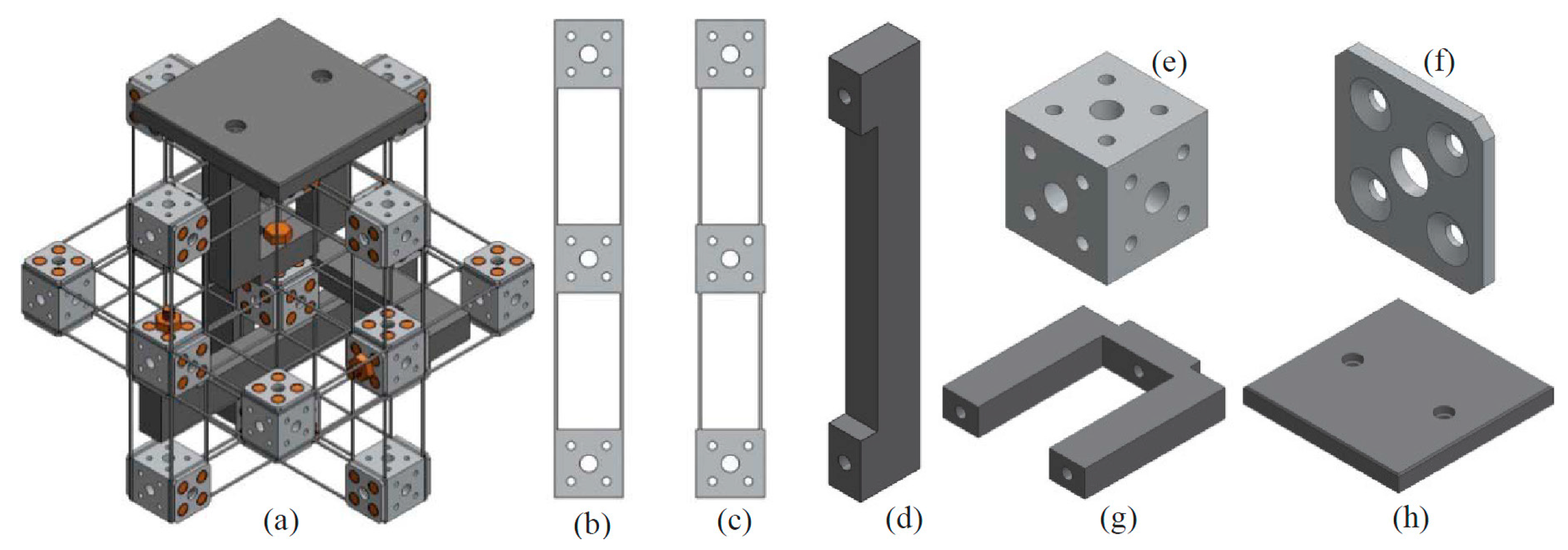
Figure 13.
Practical design-I and its assembling accessories: (a) practical design-I, (b) compliant beam component with larger spanning size, (c) compliant beam component with smaller spanning size, (d) rigid cube linkage, (e) rigid cube, (f) washer, (g) output platform linkage and (h) output platform.
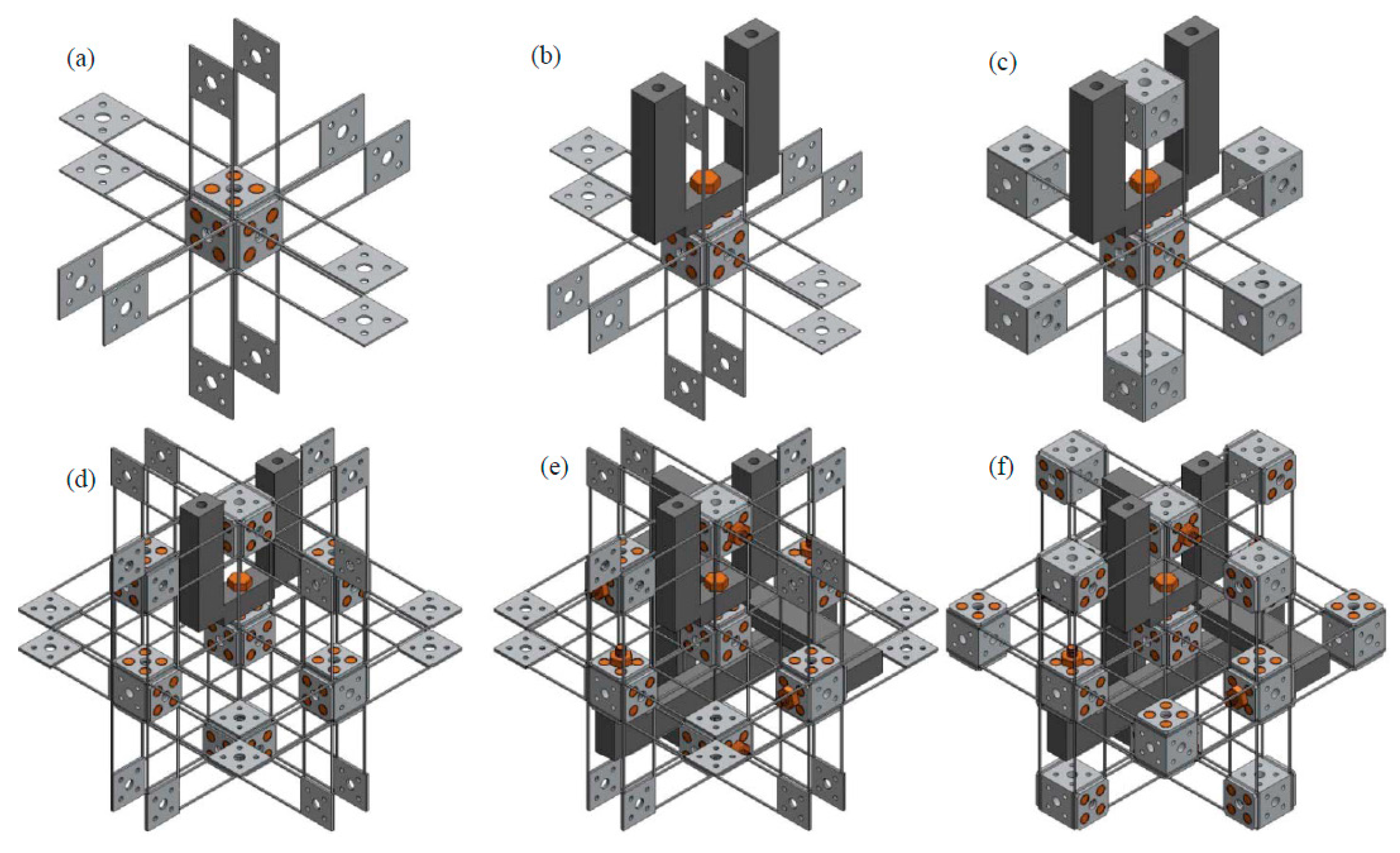
Figure 14.
Assembling process of the design-I: (a) MS and its connected compliant beam components assembly, (b) output platform linkage assembly, (c) ASs assembly, (d) AS connected compliant beam components assembly, (e) rigid cube linkage assembly and (f) other rigid cubes assembly.
Figure 14.
Assembling process of the design-I: (a) MS and its connected compliant beam components assembly, (b) output platform linkage assembly, (c) ASs assembly, (d) AS connected compliant beam components assembly, (e) rigid cube linkage assembly and (f) other rigid cubes assembly.
Design-I has only seven different basic assembling accessories. Additionally, each of the basic assembling accessories can be fabricated easily. When one of the basic assembling accessories is broken, it is convenient to replace it with a new one. Moreover, different materials can be selected for the seven basic assembling accessories. For example, one can select Al6061 for the compliant beam components, select stainless steel for the rigid cubes and cube linkages, and select Polycarbonate for the output platform and its linkage.
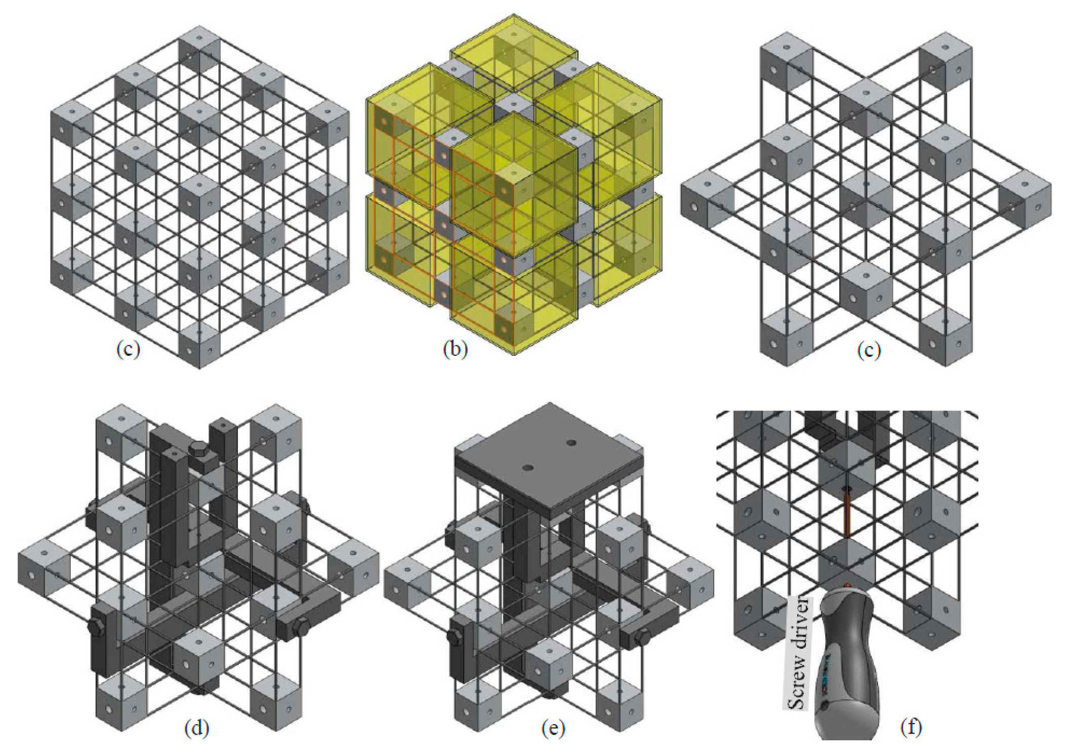
All of the rigid cubes and the compliant beam components can also be fabricated as a monolithic model, as shown in
Figure 15a. The model can be fabricated through cutting along the three orthogonal directions, using electrical discharge machining technologies. If all the beams connecting to the eight vertex cubes of the model shown in
Figure 15b are cut off, the model shown in
Figure 15c can be obtained. Note that the associated rigid cubes should be fixed when cutting a compliant beam from them. The model, as shown in
Figure 15c, is the key part of the practical design-II.
Figure 15d–e illustrate the assembling of the output platform linkage, rigid cube linkages and output platform of design-II. Using a screwdriver to assemble the output platform linkage is also shown in
Figure 15f. Compared with design-I, design-II has less assembling errors. However, the monolithic structure, as shown in
Figure 15c, of the practical design-II has to be made of a single material, and the whole structure should be replaced if only one of the compliant beams is broken.
Figure 15.
Manufacture and assembling process of the practical design-II: (a) monolithically fabricated model, (b) demonstration of the vertex cubes, (c) monolithically fabricated model without the vertex cubes, (d) output platform linkage and rigid cube linkage assembly, (e) output platform assembly and (f) demonstration of using a screwdriver to assemble the output platform linkage.
7. System Design
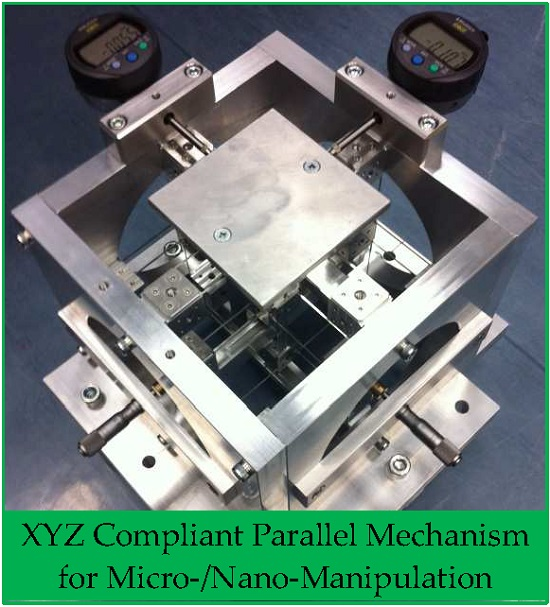
The practical designs, design-I and design-II, have many potential applications such as micro-/nano-positioning platform and nano-manufacturing. This section presents a spatial high-precision translational manipulator, which is designed using the practical design-I or the practical design-II. The spatial high-precision translational manipulator is comprised of the practical design-I or the practical design-II, supporting stand, three actuators and displacement sensors, as shown in
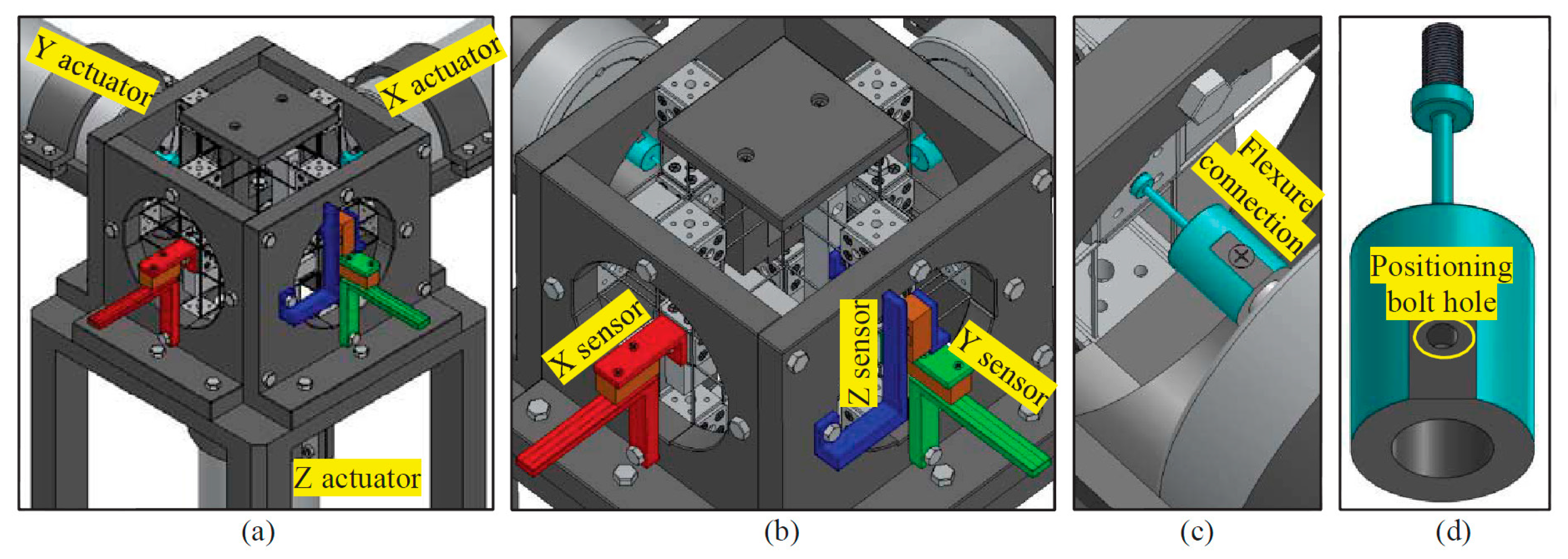
Figure 16a. The beam length, beam thickness and cube width of the spatial high-precision translational manipulator are 30, 1 and 20 mm, respectively. The peripheral dimension of the spatial high-precision translational manipulator is about 350 mm × 350 mm × 350 mm. This paper shows only the layout of the system design, while the detailed design for prototyping and experimental testing will be our further work. For the layout design, the following two key aspects should be emphasized: (a) displacement sensor assembling; and (b) actuator assembling.
In order to control the output platform at a specific position, the translational displacements of the output platform should be measured by a three-axis displacement sensor or three single-axis displacement sensors. If using three single-axis displacement sensors to measure the three translations of the output platform, each of the three single-axis displacement sensors should be capable of tolerating the other two displacements of the output platform. For convenience and decreasing the cost, we measure the displacements of the three rigid cube linkages instead of measuring the displacements of the output platform. The displacements of the three rigid cube linkages are almost the same as the displacements of the output platform along the three directions, respectively, because the lost motion rates of the proposed XYZ CPM are negligible. Furthermore, because each of the rigid cube linkages translates only along one specific direction, the displacement sensor measuring the displacement of the rigid cube linkage does not need to tolerate big transverse displacements along the other directions. Therefore, we can employ three accurate optical linear encoders to measure the displacements along the X-, Y- and Z-axes, respectively. Each optical linear encoder is comprised of a scale and a read head. The read head is used to read the encoded position from the scale.
Figure 16b shows the assembly of the three optical linear encoders. The optical linear encoder, as shown in
Figure 16b, is modeled based on a SIGNUM™ (Renishaw Public Limited Company, Gloucestershire, UK) RSLM/RELM high accuracy linear encoder system (the type number of the read head is A-9572-1514, and the type number of the scale is A-9660-0130), which can provide up to a 5-nm resolution.
Three cylindrical housed linear voice coil actuators (made by BEI Kimco Company located in Vista, CA, USA, and the type number of the actuator is LAH43-86-001Z) are selected to actuate the three translations of the high-precision spatial translational manipulator system, as shown in
Figure 16a. The actuators can offer peak force 1512.4 N, continuous stall force 386.7 N and virtually unlimited resolution. The resolution is limited only by the associated displacement sensors. As analyzed in
Section 4, the parasitic translations of the ASs are tiny. Therefore, the actuators do not suffer from off-axis displacements, even though the three actuators are rigidly connected to the three ASs, respectively. However, three flexure actuator linkages are still designed to connect the actuators with the ASs, which can be used to eliminate the assembly error effects of the actuators. Each of the flexure actuator linkages has a flexure beam, which is used to transmit the displacement from the actuator to the associated AS, as shown in
Figure 16c. The flexure beam, as shown in
Figure 16d, has one DOC along the beam and five DOF along and about other directions, so it can prevent the transmission of: (a) the assembly errors of the actuators to the ASs; and (b) the parasitic motions of the ASs to the actuators.
Figure 16.
Demonstration of a spatial high-precision translational manipulator based on the practical design-I or design-II: (a) the spatial high-precision translational manipulator, (b) translational displacement measure sensor and (c,d) flexure actuator linkage.
Figure 16.
Demonstration of a spatial high-precision translational manipulator based on the practical design-I or design-II: (a) the spatial high-precision translational manipulator, (b) translational displacement measure sensor and (c,d) flexure actuator linkage.


