1. Introduction
Automation of microfluidic functions, such as transport, storage and fluid manipulation in small volumes, is critical for successful implementation of lab-on-a-chip platforms. In a bio-analytical laboratory, the challenges associated with repetitive and labor-intensive processes can be addressed using programmable liquid handling. Significant efforts have been directed towards the development of such systems for miniaturized analysis in biological and chemical applications [
1,
2,
3,
4,
5]. The conventional approaches use structured microfluidic channel networks for transporting and confining liquids [
6]. Glass and polymers are common substrate materials in these microfluidic devices, with fabrication procedures well established [
3,
7]. Despite demonstrations of numerous applications in chemistry, medical diagnostics, chemical sensing and environmental monitoring, any changes in the device design or application typically require the development and fabrication of new devices.
Programmable microfluidic devices are reconfigurable and, hence, more versatile for on-demand liquid handling [
8]. Digital microfluidic systems exhibit such functionality and are able to manipulate discrete sample volumes (droplets). Such systems have been demonstrated in a variety of lab-on-a-chip applications using electrowetting transport [
9,
10,
11,
12], dielectrophoresis [
13,
14] and a combination of both [
15,
16,
17,
18]. Despite the advantages of discrete droplets, the high throughput capabilities afforded by continuous microfluidics in the processing of larger sample volumes cannot be easily reproduced. Recent efforts towards programmable continuous microchannels have been reported using surface energy [
17] and microvalves [
19,
20]. These early programmable devices provide continuous flow, but offer very limited re-configurability.
A programmable fluid handling platform that combines the two paradigms of continuous and digital microfluidics permits a wider range of microfluidic functions, enabling applications ranging from clinical diagnostics in resource-limited environments, to rapid system prototyping, to high throughput pharmaceutical applications. Continuous rigid channels have been incorporated with digital microfluidic platforms [
21,
22], but in that approach, the continuous channels were only used for fluid delivery to the digital microfluidic device. The concept of a platform capable of the on-demand formation of channels and droplets is illustrated in
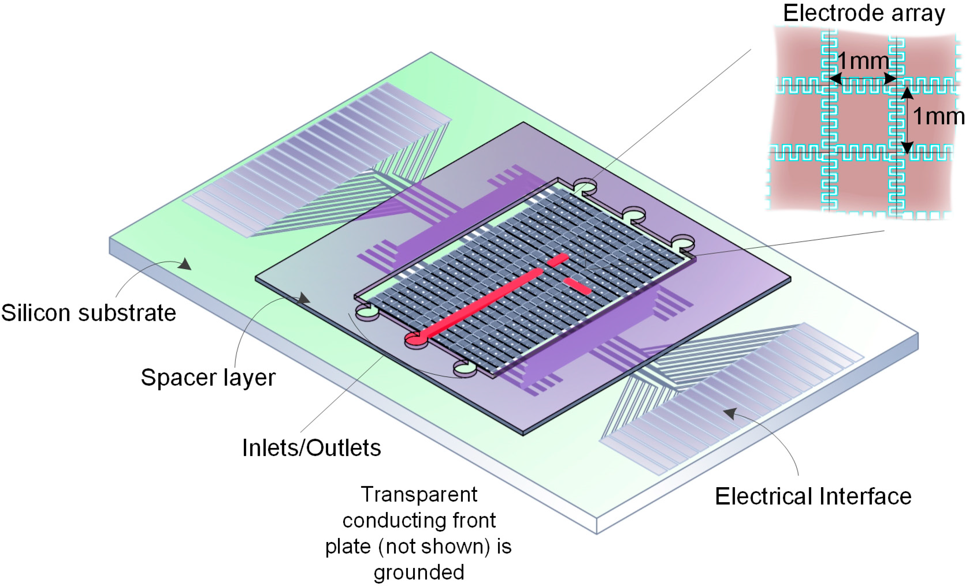
Figure 1. It relies on electrowetting contact angle modulation of the conducting aqueous samples in ambient oil over insulated electrodes, to define the boundaries of electrowetted channels or droplets. It consists of an electrically-programmable two-dimensional array of insulated electrodes on the bottom plate. The transparent top plate is conductive, and it is separated from the bottom plate by a spacer layer. This arrangement is used to form a sealed cavity with inlet and outlet ports. A computer-driven user interface lets the user define the desired channel geometry and droplet microfluidic functions to be carried out. The capability of selectively applying a potential to each electrode, combined with liquid injection using syringe pumps at the inlets, makes it possible to demonstrate a variety of fluid manipulation and handling capabilities, including continuous channel formation, splitting and merging of microfluidic channels, mixing of portioned droplets and two-dimensional liquid transport in a programmable manner.
In recent years, investigators have begun to incorporate some of the aforementioned continuous channel functionalities into digital microfluidic platforms. For example, Ahamedi
et al. used thermo-responsive microvalves to interface droplets and channels [
23], while Lin
et al. used both channels and droplets in a dielectrophoresis application [
24]. Ding
et al. demonstrated precise dispensing of volatile droplets in an electrowetting-on-dielectrics (EWOD) platform by introducing the fluid from inside of the needle tip [
25]. More recently, Chiou
et al. and Park
et al. both integrated light activation technology in EWOD to generate droplets from a channel [
26,
27]. These systems, however, either require complex experimental setups or an on-chip fluid reservoir to store the fluid to form channels and droplets. Previously, we demonstrated directional formation of virtual channels bound by polymer post arrays [
28,
29] and showed that electrowetting channels can retain their geometry under pressure-driven flows [
30]. We also showed that electrowetted fluid segments can be portioned into precisely metered volumes using voltage ramping [
31] and can be manipulated on arrayed electrodes [
32]. Most recently, we demonstrated droplet splitting from a continuous electrowetting channel, which showed an improved volume consistency [
33].
Figure 1.
Microfluidic platform based on electrowetting, integrating continuous and digital paradigms. The inset shows arrayed electrodes of size of 1 mm2. The sample in introduced through the inlet in the form of a channel, and droplets are split from the channel. The transparent conducting front plate (not shown) is grounded.
Herein, we extend our work to combine pressure-driven continuous channel formation, programmed transition between complex microfluidic structures and interaction between continuous microfluidic structures through automated droplet manipulation. This is accomplished by using an array of 360 addressable electrodes controlled through a graphical user interface (GUI). The number of addressable electrodes was extended in our system by a parallelization strategy and, thus, only has 40 input signals. Our new electrowetting addressing strategy integrates thin film transistor arrays [
8,
32]. In this scheme, a row
x column array of
n × m pixels only requires
n +
m inputs, which holds promise for large-scale programmable electrofluidic platforms. The specifics of fluid handling and associated volumes of channels and droplets are drawn from our theoretical models described previously [
30,
31]. A colorimetric glucose assay was demonstrated on this platform as a proof-of-concept. This assay was chosen, because it represents a popular and effective technique of using enzymatic reactions for detecting and quantifying disease biomarkers. The successful implementation of this assay on our device strongly suggests the adaptability of this technique for reprogrammable electrowetting devices.
2. Fabrication
The unit electrowetting electrode array consisted of 5 × 8 electrodes. Each interdigitated electrode measures 1 mm × 1 mm with a gap of 40 μm between inter-digitations, as illustrated in
Figure 1. To make a large array, nine unit arrays (total of 360 electrodes) were duplicated and connected via a multi-level inter-connection structure.
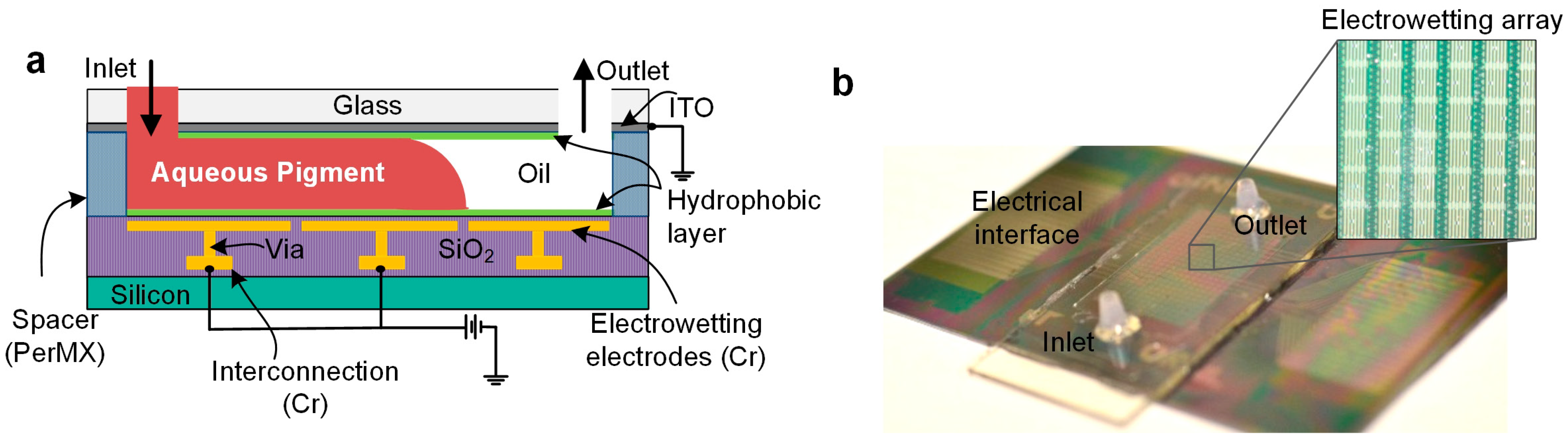
Figure 2a shows the cross-section of the electrowetting device. A 500-nm thick buffer SiO
2-coated silicon wafer was used as the initial substrate. A chromium (Cr) inter-connection layer (150 nm) was sputter deposited and subsequently lithographically patterned and wet chemically etched with a standard Cr wet etch solution (9% (NH
4)
2Ce(NO
3)
6 + 6% (HClO
4) + H
2O). A SiO
2 inter-metal dielectric layer (400 nm) was deposited at 350 °C via plasma-enhanced chemical deposition (PECVD), and an 80-μm square via holes for electrical contact were formed by photolithography and a dry etch process. Cr electrowetting electrodes (150 nm) were deposited by sputtering and subsequently lithographically patterned and wet chemically etched. A PECVD SiO
2 (300 nm) was again deposited at 350 °C for the electrowetting dielectric. The top plate consisted of an indium-tin oxide (ITO)-coated glass. To make all of the surfaces hydrophobic, the bottom and top plates were dip-coated in Cytonix FluoroPel 1601V solution and baked for 20 min at 140 °C.
A photo resist film (Dupont PerMX 5050) was used to create the requisite gap of 100 μm between the top and bottom plate. This photoresist layer was patterned to include inlet and outlet reservoirs for fluid introduction and elution. Holes were drilled on the top plate corresponding to these reservoirs. The top and bottom plates were sealed together with UV epoxy (Dymax, OP-30, Fiber Optics Center Inc., New Bedford, MA, USA). Silicone oil (Dow Corning OS-30 oil, Ellsworth, Germantown, WI, USA) was introduced as an insulating ambient medium into the device through the inlet port on the top plates.
Figure 2b shows a photograph of the complete device. Electrical connections between the electrowetting array and the data acquisition (DAQ) card were made using a customized test clip with spring loaded pins. The DAQ card was controlled by a signal-generating program using LabView software (National Instruments, Austin, TX, USA).
Figure 2.
(a) Cross-section of the electrowetting device. The aqueous fluid introduced through the inlet conforms to the shape of the activated electrodes, forming electrowetted structures. (b) Photograph of completed device with the inset showing the arrayed electrodes. The electrical interface at the edges of the device were interfaced to a power supply and controlled using a computer interface.
The user interface in LabView allows the user to control the device and turn individual electrodes in the device on or off in any desired pattern for the necessary time durations. The electrodes were activated by 40-V DC voltage to form different patterns of paths. Aqueous fluid introduced through the inlet port using a syringe pump (
Figure 2a) conforms and follows the path of the shape of the activated electrodes. Channels and droplets could be formed and manipulated in this manner. Transport, sample metering into droplets and transition between different complex geometries could all be accomplished using more elaborate voltage program sequences. Our current device was designed to address a 5 × 8 unit array of individual electrodes (40 pixels). Nine such unit arrays were connected in parallel to allow us to simultaneously replicate user input in tandem, which can be used for redundancy or parallel reaction sequences of different chemistries.
3. Results and Discussion
3.1. Electrowetting Characterization
Each aqueous fluid used on our platform exhibits its own characteristic interfacial tension. Hence, it was important to determine the voltages at which they saturate to optimize the platform as we move toward bioassay applications. This is the first time that glucose and enzyme have been characterized on our device. Using the contact angle at saturation, it is possible to determine the area of the cross-section and to estimate the volume of the electrowetted segments. Specifically, we characterized the aqueous red dye (Sun Chemical) used for all demonstrations of electrowetting functionality, as well as the reagents associated with a colorimetric glucose assay (Cayman Chemical).
Electrowetting contact angle modulation was performed by varying the applied voltage at the metal layer. The applied voltage (
V) is related to the apparent contact angle [
34,
35] θ
V by the Young–Lippmann equation [
12]:
where θ
0 is the contact angle at
V = 0 V, ϵ
0 = 8.854 × 10
−12 is the permittivity of free space, ϵ
= 3.39 is the relative permittivity of the SiO
2 layer [
36,
37],
t is the dielectric layer thickness and γ
ci is the interfacial tension between the conducting and insulating fluids. On a hydrophobic dielectric, where the Young’s angle θ
0 is approximately 180°, the contact angle can be modulated down to ~60° by applying a suitable voltage, before contact angle saturation occurs.
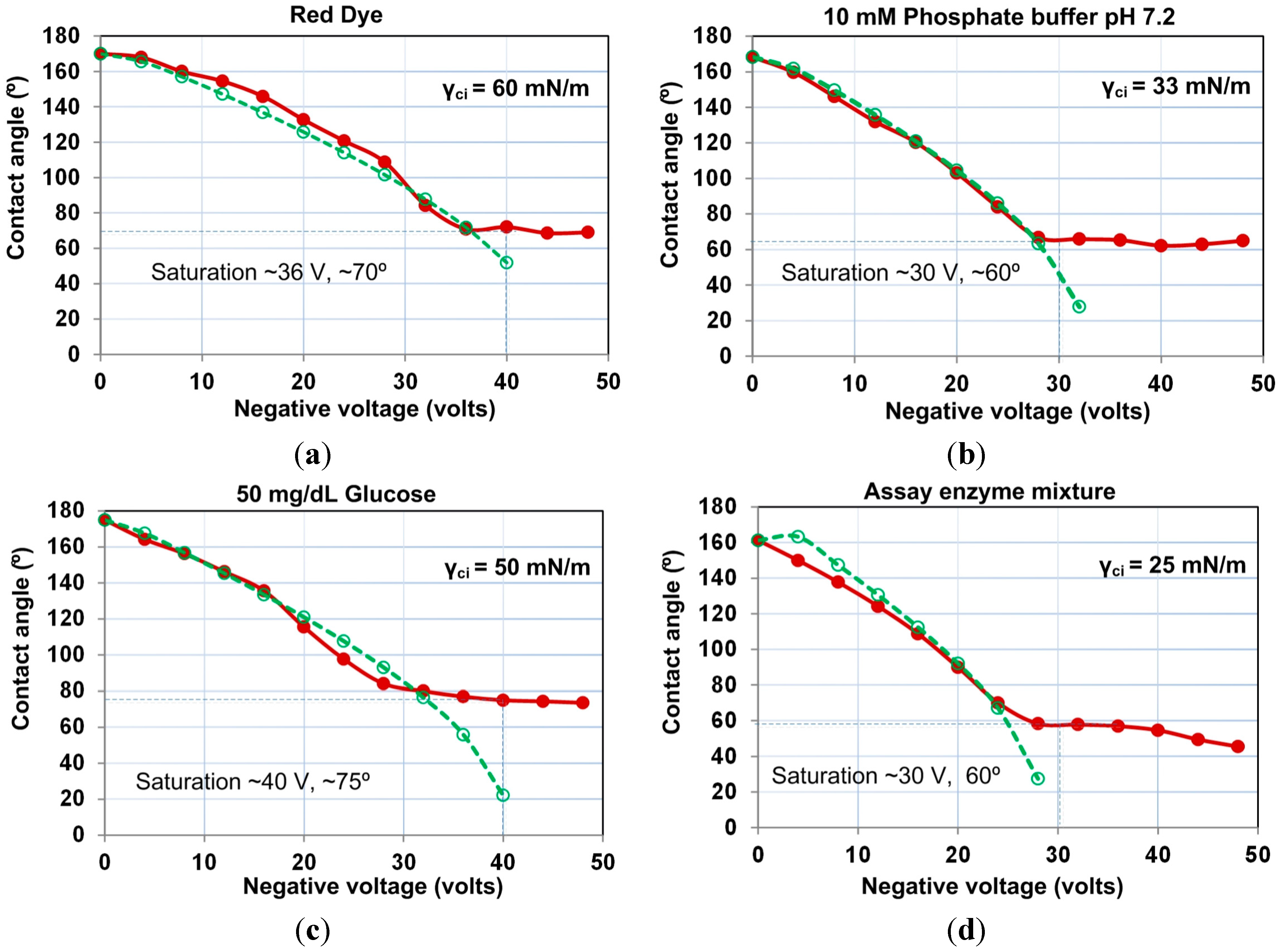
The results of these experiments indicate that all of the tested solutions exhibit contact angle saturation at ≤40 V in our electrowetting setup (
Figure 3). We thus chose this value as the operating point for all of our experiments to ensure that all of the tested samples undergo maximum contact angle modulation in our devices. Using this data, we estimated the value of the interfacial tension between the aqueous droplet and the insulating oil (γ
ci) in each case and used the Young–Lippmann equation (Equation (1)) to plot the theoretical trend. The experimental data agree with the Young–Lippmann curves within ±3°, until contact angle saturation occurs, as the Young–Lippmann model does not account for this saturation [
38] and the physical origins of this phenomenon have not yet been explained successfully.
The data from these experiments permit us to accurately calculate the volumes of these reagents over a single 1 mm × 1 mm electrode for a device height
h = 100 μm [
33]. This analysis is summarized in
Table 1. The data show that the volumes are within ~2.5 nL of each other. Although relatively small compared to the total volume accommodated over a single electrode, ~94 nL [
33], these minute variations in volume can be important in biochemical analysis. The volumes of each reagent over a unit electrode could be used to estimate the volumes of larger electrowetted segments by counting the number of electrodes.
Figure 3.
Electrowetting characterization of: (a) red dye; (b) 10 mM phosphate buffer, pH 7.2; (c) 50 mg/dL glucose; (d) assay enzyme mixture. The saturation angle varied between 60° and 75°. The dashed lines show the predicted values using the Lippmann equation, and the solid line indicates experimental observations. The maximum voltage for saturation was 40 V. Since all of the reagents saturate below this voltage, the operating point was chosen as 40 V for all experiments.
Table 1.
Volumes of the reagents over a single 1 mm × 1 mm electrode were calculated using the method stated in our previous work [
33]. The volume of longer electrowetted segments could be obtained by simply counting the number of electrodes and multiplying the corresponding unit volumes.
Table 1.
Volumes of the reagents over a single 1 mm × 1 mm electrode were calculated using the method stated in our previous work [33]. The volume of longer electrowetted segments could be obtained by simply counting the number of electrodes and multiplying the corresponding unit volumes.
| Fluid | θsat (°) | Rs (μm) | θ s (°) | A (μm2) | Volume Over One Electrode (nL) |
|---|
| Dye | 70.0 | 116.6 | 81.8 | 94,418.8 | 94.4 |
| Buffer | 60.0 | 142.9 | 72.5 | 92,743.1 | 92.7 |
| Glucose | 75.0 | 106.2 | 86.6 | 95,192.3 | 95.2 |
| Enzyme | 60.0 | 142.9 | 72.5 | 92,743.1 | 92.7 |
3.2. Demonstration of Channel Formation
Fluid introduction into electrowetting devices has been approached in a number of ways. In a two-plate electrowetting system, such as reported herein, the popular approaches include the “smashing” method, pipetting through a port in the top plate and a syringe pump. The “smash” method involves suspending a measured volume of aqueous solution in a larger droplet of oil on the bottom substrate and placing the top plate over this arrangement to smash the fluids. While this method is suitable for some droplet-based systems, it cannot be used reliably for multiple reagents and continuous channels. In the second approach, the device is prefilled with ambient oil, and aqueous reagents are pipetted through individual holes drilled on the top plate. These reagents are subsequently dispensed as smaller droplets by splitting from these larger, on-chip reservoirs. Although this method is used widely, the finite nature of the reservoirs leads to a change in droplet volume, as more droplets are dispensed from the same reservoir. The third and more recent approach uses a syringe pump to introduce fluids through inlet ports in the top plate. This technique is the most versatile of the three because of its ability to dispense controlled volumes, as well as supporting continuous flows. For these reasons, this is the approach used in this work.
In our earlier demonstration of the formation and programmed reconfiguration of continuous channels on electrowetting platforms [
30], we used electrodes shaped in the form of long channels. Herein, we expanded our capabilities by using an array of smaller 1-mm
2 electrodes. The advantage of using this arrangement is that it gives us access to a larger variety of geometries that can be programmed. Thus, we first tested channel formation and their continuous pressure-driven operation on our device to confirm that it is similar in behavior with our earlier devices [
30,
31,
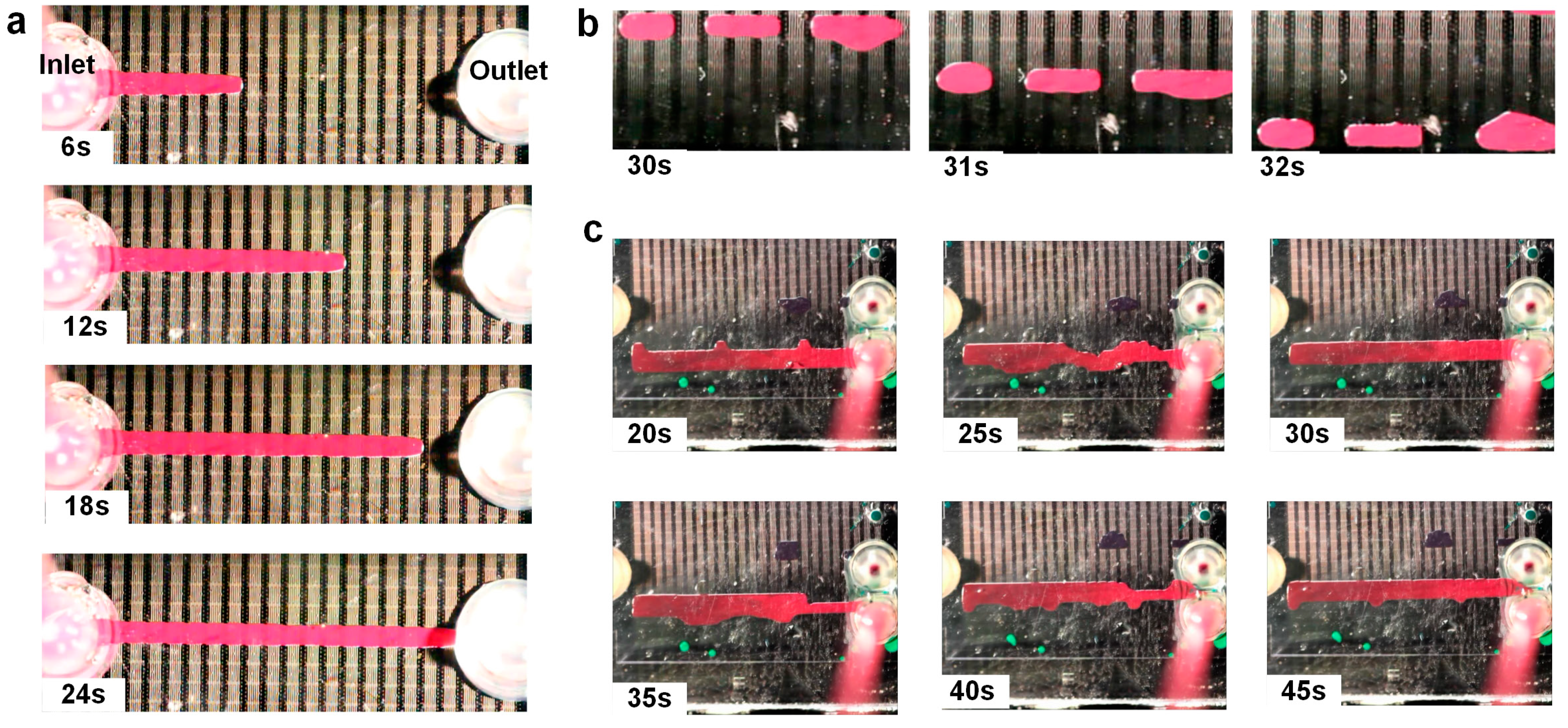
33]. The device was programmed by activating a series of 24 electrodes connecting one inlet to one outlet in a straight line, to demonstrate channel formation. Subsequently, a syringe pump was used to dispense red fluid through the inlet (
Figure 4a) at a continuous rate of 5 μL/min. The fluid meniscus showed a ratcheting motion from electrode to electrode as it moved forward (see the ESI1 video). We attribute this ratcheting motion to partial overlap at the boundary of each electrode. When each electrode electrowets the incoming fluid, it takes time to completely fill and populate the gap of the adjacent electrode, during which the meniscus appears static. As soon as the meniscus contacts the next electrode, it ratchets forward. A 24 mm-long channel was formed in this way between the inlet and outlet ports in ~24 s. The total channel volume from inlet to outlet (not including the ports) was 2.3 μL, as we estimated from the dispensed volume of the syringe pump. For a 24 mm-long channel, the volume can be simply estimated by multiplying the cross-section with the length, which yields ~2.27 μL.
Following channel formation, the long channel was split into smaller droplets of different sizes.
Figure 4b shows three droplets covering 2, 3 and 4 electrodes each. We transported these droplets repeatedly, moving each droplet at a speed of 1 mm/s, as indicated by the time-lapsed sequence. Droplet movement was achieved by activating electrodes adjacent to the droplets and then turning off the initial electrodes. This sequence was programmed into the LabView interface for each droplet, such that the droplets could be moved quickly and uniformly. The speed with which the droplets moved could be varied by changing the intervals between the activation and deactivation of electrodes. As the speed was increased, we found that larger droplets (three electrodes or more in size) could not be moved easily at higher speeds. This is due to the increased mass of the droplet, while the electrowetting force remains the same.
Figure 4.
(a) Electrodes were turned on in a straight line connecting the inlet and outlet ports. Red fluid introduced using a syringe pump forms a channel. (b) Three droplets of three different sizes were created by splitting. These droplets were then moved together. (c) A 2 mm-wide channel 24 mm in length was formed, and then, the channel was transported by sequentially tuning on rows of electrodes. Frames show channel motion upwards. Refer to ESI1 and ESI2 for videos.
Larger electrowetted structures, such as channels, can also be transported in a similar manner as droplets. To demonstrate this, we formed a straight channel, 2-mm wide, and moved it laterally across the rows of our arrayed device. Electrodes adjacent to the channel were activated in a row, and then, the row over which the channel resided was turned off to affect its motion, as illustrated in
Figure 4c. The time required for such a migration is much larger compared to the motion of smaller droplets. To shift the entire channel by 1 mm took about 5 s. It was observed that both in the case of larger droplets, as well as elongated electrowetted segments, the transport of fluid does not take place simultaneously over all of the activated rows. Typically, the fluid starts to migrate to the adjacent activated row at a particular spot, and then, the rest of the fluid channel motion follows (refer to the ESI2 video for a demonstration). The transport of larger electrowetting structures may be important in various applications, for instance where the ratio of mixing between two reagents is large. Conventionally, this is carried out by transporting multiple droplets of one reagent and mixing with one droplet of another reagent in digital microfluidics. However, this method is prone to errors, as was investigated by others [
1]. Precise droplet dispensing assisted by needles and a feedback-controlled syringe pump has also been demonstrated [
39], but increases the complexity of the entire system. Our method, on the other hand, allows users to estimate the volume of the structure in a single step and then transport it as a single body of fluid to the appropriate destination on the chip. Programmed transport of a wide range of volumes can be critical to the execution of complex biochemical analysis, such as assays.
3.3. Dynamic Channel Reconfiguration
Programmable reconfiguration of electrowetted structures permits users to change device behavior and to fine-tune its functionality without having to redesign the system. It also allows the user to carry out various functions, such as agitated mixing of two or more samples and directing droplets or continuous channels into different paths. Here, we demonstrate programmed transitions between different shapes of electrowetted structures. Six of the nine unit arrays on our device were loaded with equal volumes of red dye by forming channels through an inlet and then splitting the channel and suitably transporting the volumes to the individual unit arrays.
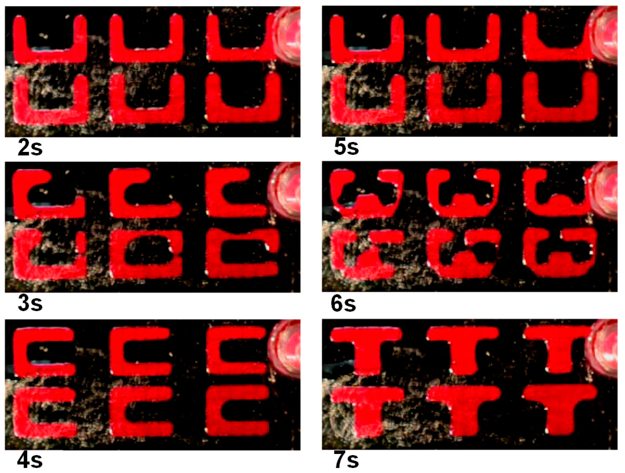
Figure 5 illustrates the scheme of the transitions. Electrodes are turned on in a “U” shape and then transitioned to a “C” shape over two seconds. In a similar manner, transitions were subsequently made to form the “T” shape and back to the “U” shape. These letters represent the collaborative efforts of the University of Cincinnati (UC) and the University of Tennessee (UT), Knoxville, on this project (see the ESI3 video). Most importantly, these transitions demonstrate a proof-of-concept for on-demand formation of complex two-dimensional microfluidic structures and their programmed reconfiguration.
Figure 5.
A six-unit array was supplied with red fluid in portioned volumes, and the user interface was programed to transition between the patterns every two seconds. Panels show the transition from U to C and U to T. Refer to ESI3 for the video.
Figure 5.
A six-unit array was supplied with red fluid in portioned volumes, and the user interface was programed to transition between the patterns every two seconds. Panels show the transition from U to C and U to T. Refer to ESI3 for the video.
3.5. Demonstration of Glucose Assay
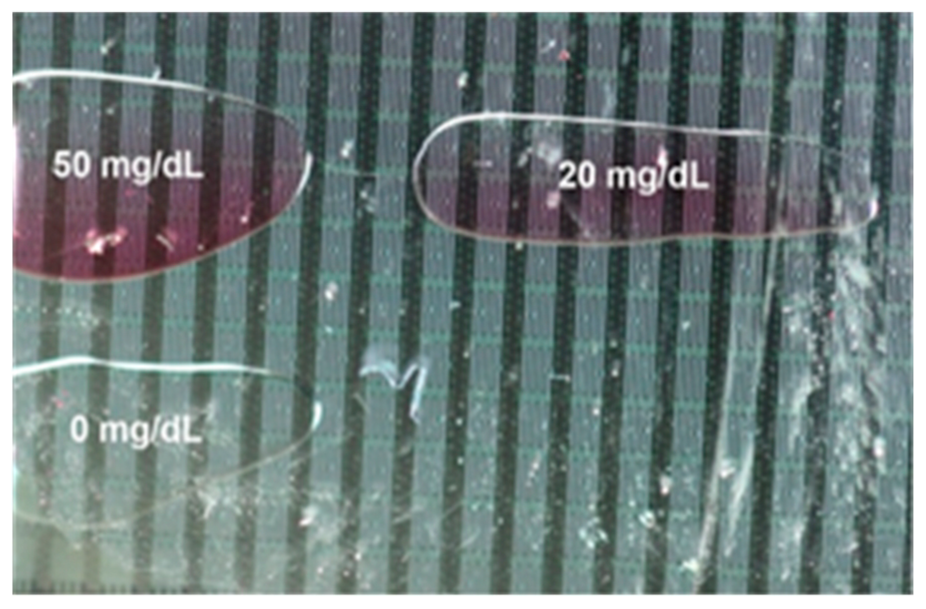
The techniques demonstrated in this work are general in nature and can be applied to a wide range of applications on electrowetting platforms. As a demonstration, we used these techniques to test a simple colorimetric glucose assay in ambient oil. Three different unit arrays on the chip were loaded with enzyme mixture (Cayman Chemical) from the glucose assay kit by forming a channel and then driving it into equal segments and suitably transporting the individual segments. Next, we introduced the glucose samples premixed with assay buffer through another inlet. Droplets of three different glucose concentrations (0, 20 and 50 mg/dL) were transported and merged with the enzyme mixture. The merged electrowetted segments were then incubated by agitation with sequential activation and deactivation of electrodes. The samples developed color according to their concentration, as exhibited in
Figure 7. The outcome of this experiment was a qualitative demonstration showing a color gradient between three different concentrations of glucose. Although the same kind of glucose assay has been previously demonstrated in digital microfluidics by other groups [
8,
39], here it serves as a demonstration of our automated multi-functional fluid handling techniques. The major hurdle while working toward on-chip demonstration of the glucose assay was that the protein molecules in the enzyme mixture tended to irreversibly stick to the hydrophobic surface of the device, causing bio-fouling, thus significant device breakdown. To overcome this hurdle, a small amount (~0.01 wt %) of pluronic solution was added into the sample.
Figure 7.
Colorimetric glucose assay demonstration on-chip showing three different glucose concentrations.
Figure 7.
Colorimetric glucose assay demonstration on-chip showing three different glucose concentrations.


