Article

Three-Dimensional Electro-Sonic Flow Focusing Ionization Microfluidic Chip for Mass Spectrometry †

1
Division of Advanced Manufacturing, Graduate School at Shenzhen, Tsinghua University, Shenzhen 518055, China
2
Shenzhen Institutes of Advanced Technology, Chinese Academy of Sciences, Shenzhen 518055, China
3
The State Key Laboratory of Precision Measurement Technology and Instruments, Tsinghua University, Beijing 100084, China
*
Authors to whom correspondence should be addressed.
This paper is an extended version of our paper presented in the 17th Annual Conference of the Chinese Society of Micro-Nano Technology, Shanghai, China, 11–14 October 2015.
These authors contributed equally to this work.
Micromachines 2015, 6(12), 1890-1902; https://doi.org/10.3390/mi6121463
Submission received: 9 November 2015 / Revised: 30 November 2015 / Accepted: 1 December 2015 / Published: 4 December 2015
(This article belongs to the Special Issue Micro/Nano Devices for Chemical Analysis)

Abstract

:
Increasing research efforts have been recently devoted to the coupling of microfluidic chip-integrated ionization sources to mass spectrometry (MS). Considering the limitations of microfluidic chips coupled with MS such as liquid spreading, dead volume, and manufacturing troubles, this paper proposed a new three-dimensional (3D) flow focusing (FF)-based microfluidic ionizing source. This source was fabricated by using the two-layer soft lithography method with the nozzle placed inside the chip. The proposed FF microfluidic chip can realize two-phase FF with liquid in air regardless of the viscosity ratio of the continuous and dispersed phases. MS results indicated that the proposed FF microfluidic chip can work as a typical electrical ionization source when supplied with high voltage and can serve as a sonic ionization source without high voltage. The electro-sonic FF ionization microfluidic chip is expected to have various applications, particularly in the integrated and portable applications of ionization sources coupling with portable MS in the future.

Graphical Abstract

1. Introduction

Electrospray ionization (ESI) mass spectrometry (MS) is vital to biological analysis because of its excellent ability to detect a great number of analytes with high sensitivity while also identifying the structural information of detected species [1,2,3]. Given the rapid development of miniaturization technology, microfluidic chips have an important function in metabolomics, proteomics, and other biochemical analyses owing to their efficient and fast separations [4,5] in integrating complex sample pretreatment functions and their automatic manipulation of small sample volumes [6,7,8,9,10]. Therefore, the coupling of microfluidic chips with MS has received considerable research interest [11], particularly the design and improvement of chip-based microfluidic ionization sources coupled with MS, which has been comprehensively reviewed by a large number of research groups [12,13,14,15].
Chip-based ESI sources are generally divided into three types. The first type is the monolithic source, which involves direct spraying from the edge of a microfluidic chip, and was earlier reported by Karger et al. [16] and Ramsey et al. [17]. Although this approach is relatively simple, the ionization source encountered liquid spreading problems along the edge of the chip, thus resulting in the formation of a large Taylor cone. Tapered fused-silica capillaries, which served as electrospray tips, were inserted into the end of the channels in the microfluidic chips to overcome this problem [18]. However, the fabrication process of this approach was complicated. Moreover, large dead volumes were generated at the interfaces between the capillaries and micro-channels, thus causing a possible degradation of electrospray performance. In recent years, an increasing number of research efforts adopted the design of integrating a nozzle in the microfluidic chip during the fabrication process [6,14]. This approach undoubtedly possesses distinct advantages compared with previous methods. Moreover, this integrated nozzle was also developed from one to multi-nozzles for high-throughput analysis [19,20]. However, all of these microfluidic chip ionization sources have only one channel of liquid for spraying and a lack air for atomization which is usually used in macro-ionization [21].
Various materials have been employed to fabricate microfluidic chips, such as silicon [22,23], polymers (SU-8) [24,25,26], polymethyl methacrylate [27], glass [28,29,30,31] and poly (dimethylsiloxane) (PDMS) [1,6,32,33]. Koster et al. [14] conducted a thorough summary of the materials used for microfluidic chips. The fabrication process of integrated nozzles on microfluidic chips was generally easier with polymers than with glass [34,35]. Among these polymers, PDMS was a widely used material for microfluidic chips because of its chemical inertness, low cost, and rapid fabrication process by soft lithography [36]. Furthermore, compared with the hydrophilic surface of glass, the hydrophobic surface of PDMS can effectively prevent the solution from wetting the nozzle; otherwise, the wetted surface may preclude the operation at nano-ESI flow rates and lead to unstable electrospray [1,37]. However, forming an excellent electrospray nozzle integrated on the microfluidic chip was difficult because the PDMS was soft and the tip was too small to cut at the two sides of the micro-channel front end. A raised layer cutting method by two-layer soft lithography was proposed in our previous work [38]. Furthermore, the electrospray nozzle was exposed outside and was prone to damage [1,6,32,33,39,40].
Inspired by flow focusing (FF) technology [41,42,43,44,45,46,47,48,49], we designed an inner electrospray nozzle that has a Taylor cone at the front end of the liquid (dispersed phase) channel focused by the air (continuous phase) inside the microfluidic chip. This water in the air FF regime was first implemented by using a coaxial capillary tube closed to a small hole in a thin plate [50,51,52,53,54]. However, the fabrication processes were complicated and coupling such devices with other microfluidic modules was difficult. For microfluidic FF, two-dimensional (2D) microfluidic FF chips always require dispersed and continuous phases with low viscosity ratios (approximately 0.1) [55], such as water in oil [41] and air in water [47]. The high viscosity ratio is also barely implemented because the 2D micro-channel will form a shear flow and the dispersed phase will not break [56,57,58,59]. Alternatively, the three-dimensional (3D) microfluidic FF chip, in which the dispersed phase was suspended in the continuous phase without contacting the micro-channel wall, can guarantee the formation of extensional flow. This 3D microfluidic FF chip is suitable for applications with low viscosity ratios, such as generating submicron emulsion droplets and cell counting [49,60,61] and high viscosity ratios. Although the 3D microfluidic FF chip was recently implemented by Trebbin et al. [62] at a high viscosity ratio to produce liquid jets and droplets, we conceived and designed a similar 3D microfluidic FF chip independently and differently. Compared with the three-layer structure of Trebbin et al., we fabricated the microfluidic chip by two soft lithography layers with the nozzle inside the microfluidic chip to simplify the fabrication and alignment processes and protect the nozzle from damage. Furthermore, the 3D microfluidic FF chip implemented in the current paper was adopted as an ionization source. MS data were collected to verify the ionization performances with different applied voltages. In the rest of the paper, we mainly demonstrated the fabrication process of the proposed microfluidic chip by two-layer soft lithography. A corresponding 2D microfluidic FF chip was also fabricated, and the spray effects of the 2D and the 3D microfluidic chips were compared. The jet diameter of the dispersed phase from the 3D microfluidic chip was measured with the changes of the dispersed phase flow rate and the continuous phase pressure. Furthermore, we also show the simple application of the proposed microfluidic chip coupled with MS. The results indicated that such a microfluidic chip can obtain stable MS signals with and without high voltage supply. We called this microfluidic chip with an ion source the electro-sonic FF ionization (ESFFI) microfluidic chip, which has a potential for portable and on-site applications in the future.

2. Materials and Methods

2.1. Materials and Equipment

HPLC-grade methanol and acetic acid were purchased from Merck KGaA (Darmstadt, Germany). PDMS elastomer base and curing agent (Sylgard 184) were purchased from Dow Corning (Midland, MI, USA). SU-8 photoresist was obtained from Microchem Co. (Naton, MA, USA). All dispersed and continuous phases were supplied to the microfluidic chip through short stainless steel tubes embedded in the reservoirs using a pneumatic pressure controller (MFCS, Fluigent, Paris, France). This pneumatic pressure controller allowed almost non-fluctuating flow, which was essential to form a steady Taylor cone. The high voltage generated by a power supply module (Dongwen High Voltage Power Supply Co., Ltd, Tianjin, China) was applied on the stainless steel tube of the dispersed phase. A high-speed camera (ORCA-flash, Hamamatsu, Shizuoka, Japan) mounted on an inverted optical microscope (Eclipse TE 2000-U, Nikon, Tokyo, Japan) was used to observe the experiments. An ion trap mass spectrometer (Thermo Fisher Scientific Inc., Waltham, MA, USA) was coupled to the microfluidic chip, and MS data were collected by the computer.

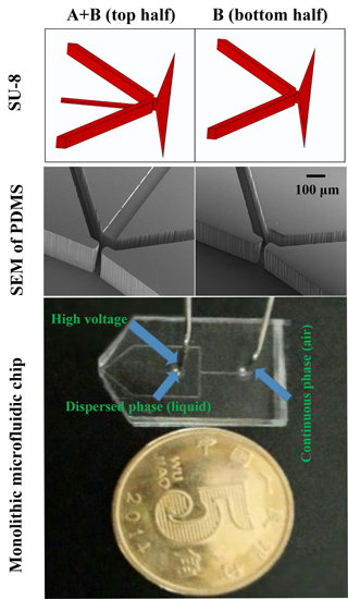
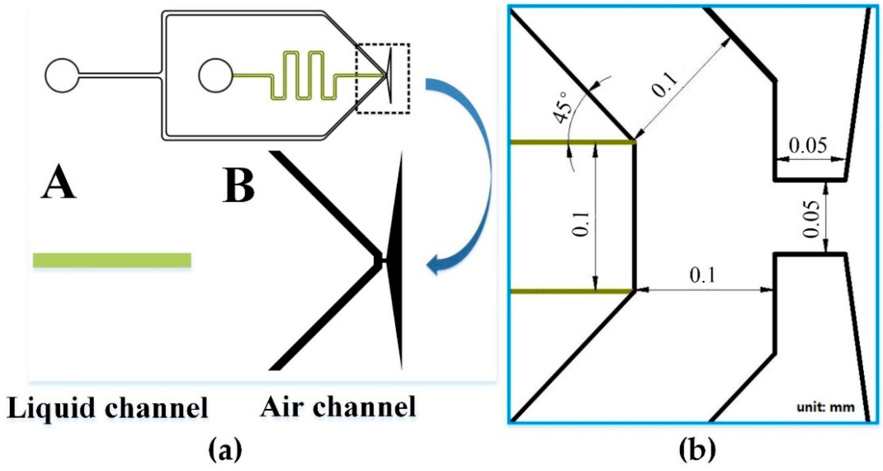
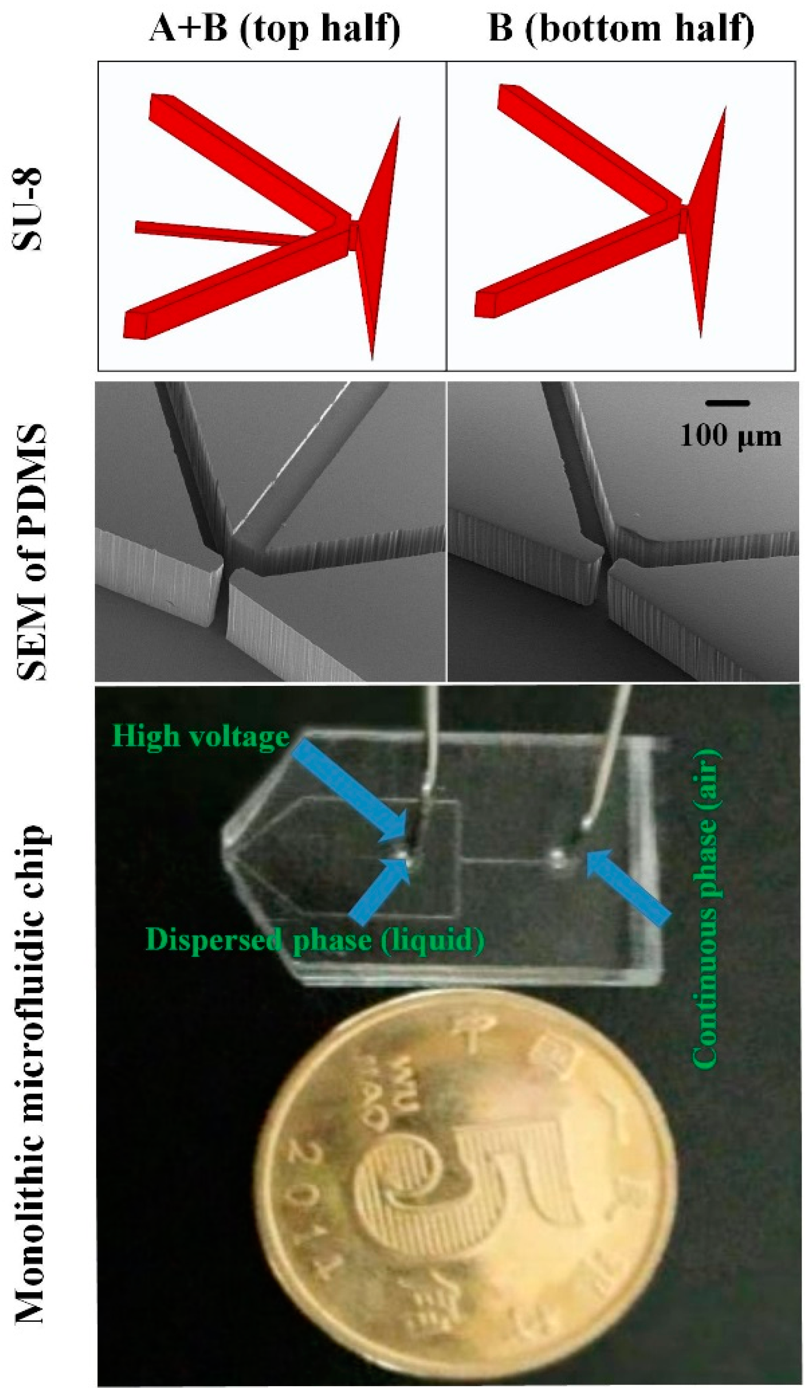
2.2. ESFFI Microfluidic Chip Design

In most cases, the top and bottom halves of the nozzle tend to separate at the tip, thus seriously affecting the spray effect. A Taylor cone was generated inside the microfluidic chip in this paper to avoid this drawback. Moreover, the proposed structure and corresponding fabrication process avoided the trouble of cutting along the edge of the nozzle outlet. The trumpet-shaped outlet was instead cut far from the nozzle (Figure 1a), thus greatly improving the craftwork and allowing the rapid mass production of microfluidic chips. The ESFFI microfluidic chip was designed by using AutoCAD (Autodesk, Inc., San Rafael, CA, USA). The photo mask and nozzle size of the ESFFI microfluidic chip are presented in Figure 1. In this paper, two photo masks (patterns illustrated in Figure 1a) were manufactured by Qingyi Precision Mask Making Co., Ltd (Shenzhen, China). The heights of the liquid and air channels were approximately 25 and 320 μm, respectively. An air channel higher than the liquid channel leads to a better focus effect because a higher air channel is beneficial for the dispersed phase to suspend in the continuous phase without coming into contact with micro-channel walls.
Figure 1. Photo mask and nozzle size of the ESFFI microfluidic chip. (a) Photo mask of the ESFFI microfluidic chip. (b) Nozzle size of the ESFFI microfluidic chip.
Micromachines 06 01463 g001

2.3. Fabrication of the ESFFI Microfluidic Chip

The ESFFI microfluidic chip was fabricated by using standard multilayer soft lithography techniques [63,64]. The fabrication process is shown in Supplementary Materials Figure S1. First, a 3 inches silicon wafer template was treated in oxygen plasma (PDC-M, Chengdu Mingheng Science & Technology Co., Ltd, Chengdu, China) to prevent SU-8 photoresist from spalling. The negative photoresist (SU-8 2025) was then poured on the silicon wafer. After spinning and soft-baking, the photoresist was exposed via photo mask A, which served as the liquid channel layer, providing an orifice and a channel for the dispersed phase. After post-baking and cooling, a second layer of negative photoresist (SU-8 2100) was applied at the top of the liquid channel layer without developing uncross-linked photoresist. After spinning and soft-baking, photo mask B, which was aligned with the liquid channel layer by a UV aligner, was placed on the second layer photoresist for exposure. This second layer served as the air channel layer with the channels and orifice for the continuous phase. After post-baking and cooling, the SU-8 photoresist layers were developed in propylene glycol methyl ether acetate and were then placed on the thermostatic platform for hard-baking. This SU-8 master mold served as the top layer of our micro-channel structure. Another SU-8 master mold with patterns of photo mask B only was prepared on another 3 inches silicon wafer template for the bottom PDMS micro-channel half-devices. This SU-8 master mold only had an air channel; thus, the fabrication process needed exposure only once. The final structures of the SU-8 master mold are illustrated in Figure 2.
Figure 2. (Top)Top and bottom SU-8 master molds; (Middle) Top and bottom structures of PDMS under SEM; (Bottom) monolithic microfluidic chip.
Micromachines 06 01463 g002
The SU-8 master molds were modified with vapor-phase TMCS (Chlorotrimethylsilane) to assist the release of PDMS membranes. PDMS base monomer and curing agent were mixed at 10:1 and 5:1 weight ratios and then poured on the top and bottom SU-8 master molds, respectively. After degassing under vacuum, these two half-pieces were cured in an oven at 80 °C for 2 h. Subsequently, two PDMS slabs were peeled off from the two master molds and the inlet holes were drilled at the top by using a punch (tip diameter of 0.75 mm). Figure 2 also shows the two PDMS slabs under a scanning electron microscope (SEM). In general, great attention should be paid in removing the excess PDMS along the nozzle tips with a razor blade. However, in this paper, a razor blade was only required to cut off the excess PDMS along the expansion trumpet-shaped outlet far from the nozzle. Both PDMS slabs, which were treated in oxygen plasma (PDC-M, Chengdu Mingheng Science & Technology Co., Ltd, Chengdu, China), were then bonded together by using an xyz-manipulator (Beijing Optical Century Instrument Co., Ltd., Beijing, China). Following assembly, the PDMS microfluidic chip was cured at 80 °C for 72 h to enhance the strength of the bonding and to eliminate the MS background from PDMS. The final monolithic microfluidic chip is shown in Figure 2.

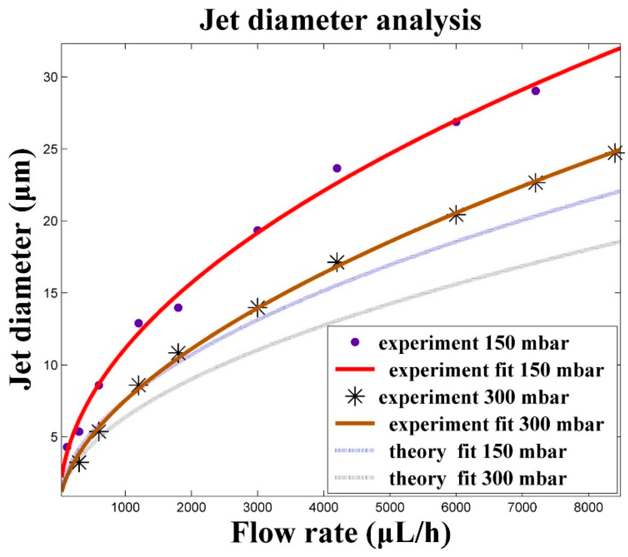
3. Results and Discussions

For the 2D micro-channel, most research efforts have focused on the low viscosity ratio of the dispersed phase and continuous phase, such as water in oil [41] and air in water [47]. For comparison, a corresponding 2D micro-channel was fabricated in this paper and the high viscosity ratio of the dispersed phase and continuous phase was performed. The spray effect of the 2D microfluidic chip in Figure 3 shows that the dispersed phase was separated into two layers (arrow pointed). The shear force caused by the viscosity of the walls prevented the dispersed phase from separation.
Figure 3. Spray effect of the 2D and 3D microfluidic chips. Pressures on the continuous and dispersed phases were 300 and 210 mbar, respectively. High voltage (2 kV) was added on the dispersed phase. The arrow pointed to the two layers of the liquid separated by the shear force of the walls.
Micromachines 06 01463 g003
However, for the 3D microfluidic FF chip proposed in this paper, the dispersed phase was suspended in the continuous phase without contacting the micro-channel walls, thus allowing this phase to separate at the high viscosity ratio. Figure 3 shows the perfect spray effect of the 3D microfluidic chip, in which a steady thin liquid jet was smoothly emitted from the Taylor cone inside the microfluidic chip and extended over several millimeters out of the microfluidic chip; this effect was similar to the liquid jet from the macrostructure device [54] and microfluidic chip [62] for FF. Under this circumstance, dead volume and liquid spreading problems, which often occur in microfluidic chips for MS, were successfully settled. Figure 4 shows the details of the jet diameters with the changes of the dispersed phase flow rates. With increasing dispersed phase flow rates, the liquid jet diameters increased in power (Figure 5). The dispersed phase flow rates varied from 120 to 8400 μL/h, and the pressures on the continuous phase were 150 and 300 mbar. However, the jet diameters in our study were larger than the data calculated from the theoretical formula [54] as shown in Equation (1):
d j = ( 8 ρ l π 2 P g ) 1 / 4 Q 1 / 2
where ρ l is the density of the dispersed phase, P g is the pressure drop of the continuous phase, and Q is the dispersed phase flow rate; these phases presented similar power function relationships, thus revealing that such a microfluidic liquid jet system may share the same underlying physics with the well-studied orifice plate configuration [62]. The differences between the rectangular channels and circular pipelines might contribute to the error. Moreover, the selected position of the jet diameter and measurement error might also introduce data dissimilarity. In general, the liquid jet diameter was proportional to the ratio of the pressure applied on the dispersed phase and continuous phase.
This microfluidic chip can be widely used in various fields in which micron or sub-micron liquid jets are generated, such as inkjet printing, pharmaceutical formulations [62] and MS. As an example application of this ESFFI microfluidic chip, we presented the experiment of coupling this microfluidic chip with MS. Figure 6 displays the configuration of the ESFFI microfluidic chip with the mass spectrometer. The microfluidic chip was held by a laboratory-built platform and coupled to the ion trap mass spectrometer. The distance between the microfluidic chip emitter and the MS inlet orifice is about 2–10 mm, which was adjusted by a xyz-manipulator.
Figure 4. Jet diameter changes with dispersed phase flow rates under the gas pressure of 150 mbar. The red box presents the position of the liquid jet diameter.
Micromachines 06 01463 g004
Figure 5. Comparison of experimental data with theoretical predictions for jet diameter and breakup transition analyses.
Micromachines 06 01463 g005
Figure 6. The configuration of the xyz-manipulator microfluidic chip with the mass spectrometer.
Micromachines 06 01463 g006
Figure 7 shows the MS signal of 41.5 μM Reserpine in 3/1 (v/v) methanol/water with 0.2% formic acid, the gas pressures for the liquid channel and air channel were about 250 mbar and 300 mbar, respectively, the high voltage added on the liquid channel was 5 kV. Figure 7a is the 10 min mean signal of reserpine and the signal stability is shown in Figure 7b; the relative standard deviation (RSD) for the total ion current (TIC) was 5.02%. To further demonstrate the stability of this microfluidic chip, the batch-to-batch reproducibility of three chips were displayed in Figure 8. The experimental conditions were the same as the signal shown in Figure 7. The mean TICs for chip 1 to 3 were 1.17 × 10⁶, 8.87 × 10⁵, and 8.4 × 10⁵, respectively; chip 1 had a slightly high TIC. However, the base peak mean intensity of these three chips was about 5.32 × 10⁴, which verified the batch-to-batch reproducibility and stability of the proposed ESFFI microfluidic chip. Moreover, several samples with lower-concentration Rhodamine B solution were tested, and the MS spectra with a 0.01 μM analyte is shown in Figure 9. The Rhodamine B signal intensity is at the level of 102 ion counts, and can be estimated to be more than three times larger than the nearby baseline signal (although there are existing several miscellaneous peaks with the same level). Thus, we can speculate that, though not rigorously, the limit of detection of such an electro-sonic flow focusing ionization microfluidic chip for Rhodamine B can be lower than 0.01 μM.
Figure 7. MS signal of 41.5 μM Reserpine in 3/1 (v/v) methanol/water with 0.2% formic acid, the gas pressures for the liquid channel and air channel were about 250 mbar and 300 mbar, respectively, and the high voltage added on liquid channel was 5 kV. (a) Reserpine ion counts of the 10 min mean signal. (b) Reserpine signal stability of 10 min; TIC mass range from 550 to 850.
Micromachines 06 01463 g007
Figure 8. The batch-to-batch reproducibility of three chips. The conditions for three chips were the same: 41.5 μM Reserpine in 3/1 (v/v) methanol/water with 0.2% formic acid, the gas pressures for the liquid channel and air channel were about 250 and 300 mbar, respectively, and the high voltage added on the liquid channel was 5 kV. TIC mass range from 550 to 850.
Micromachines 06 01463 g008
Figure 9. MS signal of 0.01 μM Rhodamine B in methanol with 0.2% formic acid, the gas pressures for the liquid channel and air channel were about 250 and 300 mbar, respectively, and the high voltage added on the liquid channel was 5 kV.
Micromachines 06 01463 g009
Figure 10 shows the MS signal of 6 μM Rhodamine B in methanol with 0.2% formic acid, which was the mean signal within 30 s. Figure 10a shows the signal of the ESFFI microfluidic chip without high voltage (i.e., the sonic FF ionization (SFFI) mode). Figure 10b demonstrates the signal of the ESFFI microfluidic chip with high voltage (4 kV) (i.e., the ESFFI mode). Figure 10c shows the signal of the commercial ESI source with high voltage (4 kV). The signal-to-noise ratios (SNR) of the SFFI mode, the ESFFI mode, and the commercial ESI source were 54, 31, and 14, respectively. The SNR of the SFFI mode was nearly two times larger than that of the ESFFI mode and three times larger than that of the commercial ESI source. Although the signal intensity can be enhanced greatly with high voltage (Figure 10b,c), the relative intensity without high voltage (Figure 10a) was enough to analyze the samples because of the high SNR. The characteristics of the SFFI mode with high SNR and low signal intensity were consistent with sonic spray ionization (SSI) [65,66].
Figure 10. MS spectra of the 6 μM solution of Rhodamine B molecules in methanol with 0.2% formic acid. The flow rate of the solution was 20 μL/min, and the gas pressure for the ESFFI microfluidic chip was 300 mbar. (a) ESFFI microfluidic chip without high voltage; (b) ESFFI microfluidic chip with 4 kV; (c) Commercial ESI sources with 4 kV.
Micromachines 06 01463 g010
In most cases, a high voltage was always applied on the ESI sources except for the SSI [65,66]. In the present paper, an ionization source coupled with MS without high voltage was realized in the ESFFI microfluidic chip, thus possibly introducing significant convenience when a high voltage is unavailable. Under such an SFFI mode, given that the velocity of the gas flow in the outlet was estimated to be similar to the sonic speed, we supposed that the mechanism of this gaseous ion formation might be the same as SSI; this mechanism was mainly assumed to be the charge residue model [67]. However, when electricity was applied on the ESFFI microfluidic chip, such an ESFFI mode was mainly similar to the ESI source. Electricity was the main energy source for gaseous ion formation even though high-velocity gas flow also made contributions to gaseous ion formation. In both cases, gas flow played an important role of FF and assisted liquid atomizing, thus successfully settling the problems of dead volume and the limitation of ionization methods in the microfluidic chip. Furthermore, the pressure on the gas flow was nearly an order of magnitude lower than the macrostructure SSI. Therefore, the SFFI mode was more suitable for portable and integration applications on MS in the future, whereas the ESFFI mode could be applied to analyze various samples. For detailed applications, interested readers could refer to the macrostructure of electro-SSI [68]. Although the intensity of the SFFI mode was low in this report, recent works [69,70] have alleviated the ion suppression effect. On the basis of the current work, efforts will be performed in our future work to optimize the structure to realize self-aspirated samples by using the negative pressure caused by the high-velocity gas flow in the microfluidic chip. The driven forces for the liquid channel might be ignored, which will further simplify the accessory equipment for portable applications.

4. Conclusions

A new 3D ESFFI microfluidic chip structure was proposed to successfully realize steady water in air FF with the nozzle inside the microfluidic chip by simple fabrication craft. This ESFFI microfluidic chip combined the liquid and air in one channel; this process was beneficial for liquid atomizing. The measurement results demonstrated that this approach fully avoided the disadvantages of the microfluidic chips coupled with MS including liquid spreading, dead volume, and manufacturing troubles. This approach also realized sample ionization in the microfluidic chip without the assistance of high voltage. These properties might make significant contributions to the integration and portable applications of ionization sources coupled with MS. In addition to the MS field, this microfluidic chip might also be widely used in other fields such as inkjet printing and microfiber spinning in which micron liquid jets are needed.

Supplementary Materials

The following are available online at https://www.mdpi.com/2072-666X/6/12/1463/s1 , Figure S1: Fabrication process of the 3D ESFFI microfluidic chip.

Acknowledgments

This work is supported by the National Natural Science Foundation of China (Grant No. 81201165) and the Interdiscipline Research and Innovation Fund of Graduate School at Shenzhen of Tsinghua University (Grant No. JC20140005).

Author Contributions

Xiang Qian designed the experiments and revised the paper; Cilong Yu performed the experiments and wrote the paper; Yan Chen optimized the fabrication process and revised the paper; Quan Yu analyzed the mass spectrometer data; Kai Ni designed the homemade electrical and mechanical setup; Xiaohao Wang organized and revised the paper. All authors were involved in the preparation of this manuscript.

Conflicts of Interest

The authors declare no conflict of interest.

References

  1. Sun, X.; Kelly, R.T.; Tang, K.; Smith, R.D. Membrane-Based Emitter for Coupling Microfluidics with Ultrasensitive Nanoelectrospray Ionization-Mass Spectrometry. Anal. Chem. 2011, 83, 5797–5803. [Google Scholar] [CrossRef] [PubMed]
  2. Liu, T.; Belov, M.E.; Jaitly, N.; Qian, W.J.; Smith, R.D. Accurate mass measurements in proteomics. Chem. Rev. 2007, 107, 3621–3653. [Google Scholar] [CrossRef] [PubMed]
  3. Aebersold, R.; Mann, M. Mass spectrometry-based proteomics. Nature 2003, 422, 198–207. [Google Scholar] [CrossRef] [PubMed]
  4. Culbertson, C.T.; Jacobson, S.C.; Ramsey, J.M. Microchip devices for high-efficiency separations. Anal. Chem. 2000, 72, 5814–5819. [Google Scholar] [CrossRef] [PubMed]
  5. Jacobson, S.C.; Culbertson, C.T.; Daler, J.E.; Ramsey, J.M. Microchip structures for submillisecond electrophoresis. Anal. Chem. 1998, 70, 3476–3480. [Google Scholar] [CrossRef]
  6. Sun, X.; Kelly, R.T.; Tang, K.; Smith, R.D. Ultrasensitive nanoelectrospray ionization-mass spectrometry using poly(dimethylsiloxane) microchips with monolithically integrated emitters. Analyst 2010, 135, 2296–2302. [Google Scholar] [CrossRef] [PubMed]
  7. Huang, B.; Wu, H.K.; Bhaya, D.; Grossman, A.; Granier, S.; Kobilka, B.K.; Zare, R.N. Counting low-copy number proteins in a single cell. Science 2007, 315, 81–84. [Google Scholar] [CrossRef] [PubMed]
  8. Lazar, I.M.; Trisiripisal, P.; Sarvaiya, H.A. Microfluidic liquid chromatography system for proteomic applications and biomarker screening. Anal. Chem. 2006, 78, 5513–5524. [Google Scholar] [CrossRef] [PubMed]
  9. Qu, H.Y.; Wang, H.T.; Huang, Y.; Zhong, W.; Lu, H.J.; Kong, J.L.; Yang, P.Y.; Liu, B.H. Stable microstructured network for protein patterning on a plastic microfluidic channel: Strategy and characterization of on-chip enzyme microreactors. Anal. Chem. 2004, 76, 6426–6433. [Google Scholar] [CrossRef] [PubMed]
  10. Sakai-Kato, K.; Kato, M.; Toyo'oka, T. Creation of an on-chip enzyme reactor by encapsulating trypsin in sol-gel on a plastic microchip. Anal. Chem. 2003, 75, 388–393. [Google Scholar] [CrossRef] [PubMed]
  11. Oleschuk, R.D.; Harrison, D.J. Analytical microdevices for mass spectrometry. TrAC Trend. Anal. Chem. 2000, 19, 379–388. [Google Scholar] [CrossRef]
  12. Gao, D.; Liu, H.X.; Jiang, Y.Y.; Lin, J.M. Recent advances in microfluidics combined with mass spectrometry: Technologies and applications. Lab Chip 2013, 13, 3309–3322. [Google Scholar] [CrossRef] [PubMed]
  13. Lin, S.; Bai, H.; Lin, T.; Fuh, M. Microfluidic chip-based liquid chromatography coupled to mass spectrometry for determination of small molecules in bioanalytical applications. Electrophoresis 2012, 33, 635–643. [Google Scholar] [CrossRef] [PubMed]
  14. Koster, S.; Verpoorte, E. A decade of microfluidic analysis coupled with electrospray mass spectrometry: An overview. Lab Chip 2007, 7, 1394–1412. [Google Scholar] [CrossRef] [PubMed]
  15. Sung, W.C.; Makamba, H.; Chen, S.H. Chip-based microfluidic devices coupled with electrospray ionization-mass spectrometry. Electrophoresis 2005, 26, 1783–1791. [Google Scholar] [CrossRef] [PubMed]
  16. Xue, Q.F.; Foret, F.; Dunayevskiy, Y.M.; Zavracky, P.M.; McGruer, N.E.; Karger, B.L. Multichannel microchip electrospray mass spectrometry. Anal. Chem. 1997, 69, 426–430. [Google Scholar] [CrossRef] [PubMed]
  17. Ramsey, R.S.; Ramsey, J.M. Generating electrospray from microchip devices using electroosmotic pumping. Anal. Chem. 1997, 69, 1174–1178. [Google Scholar] [CrossRef]
  18. Li, J.; Thibault, P.; Bings, N.H.; Skinner, C.D.; Wang, C.; Colyer, C.; Harrison, J. Integration of Microfabricated Devices to Capillary Electrophoresis-Electrospray Mass Spectrometry Using a Low Dead Volume Connection: Application to Rapid Analyses of Proteolytic Digests. Anal. Chem. 1999, 71, 3036–3045. [Google Scholar] [CrossRef] [PubMed]
  19. Mao, P.; Gomez-Sjoberg, R.; Wang, D. Multinozzle Emitter Array Chips for Small-Volume Proteomics. Anal. Chem. 2013, 85, 816–819. [Google Scholar] [CrossRef] [PubMed]
  20. Mao, P.; Wang, H.; Yang, P.; Wang, D. Multinozzle Emitter Arrays for Nanoelectrospray Mass Spectrometry. Anal. Chem. 2011, 83, 6082–6089. [Google Scholar] [CrossRef] [PubMed]
  21. Covey, T.R.; Thomson, B.A.; Schneider, B.B. Atmospheric pressure ion sources. Mass Spectrom. Rev. 2009, 28, 870–897. [Google Scholar] [CrossRef] [PubMed]
  22. Su, S.; Gibson, G.T.T.; Mugo, S.M.; Marecak, D.M.; Oleschuk, R.D. Microstructured Photonic Fibers as Multichannel Electrospray Emitters. Anal. Chem. 2009, 81, 7281–7287. [Google Scholar] [CrossRef] [PubMed]
  23. Mery, E.; Ricoul, F.; Sarrut, N.; Constantin, O.; Delapierre, G.; Garin, J.; Vinet, F. A silicon microfluidic chip integrating an ordered micropillar array separation column and a nano-electrospray emitter for LC/MS analysis of peptides. Sens. Actuator B Chem. 2008, 134, 438–446. [Google Scholar] [CrossRef]
  24. Arscott, S. SU-8 as a material for lab-on-a-chip-based mass spectrometry. Lab Chip 2014, 14, 3668–3689. [Google Scholar] [CrossRef] [PubMed]
  25. Sikanen, T.; Tuomikoski, S.; Ketola, R.A.; Kostiainen, R.; Franssila, S.; Kotiaho, T. Analytical characterization of microfabricated SU-8 emitters for electrospray ionization mass spectrometry. J. Mass Spectrom. 2008, 43, 726–735. [Google Scholar] [CrossRef] [PubMed]
  26. Sikanen, T.; Heikkilä, L.; Tuomikoski, S.; Ketola, R.A.; Kostiainen, R.; Franssila, S.; Kotiaho, T. Performance of SU-8 Microchips as Separation Devices and Comparison with Glass Microchips. Anal. Chem. 2007, 79, 6255–6263. [Google Scholar] [CrossRef] [PubMed]
  27. Lee, J.; Soper, S.A.; Murray, K.K. Development of an efficient on-chip digestion system for protein analysis using MALDI-TOF MS. Analyst 2009, 134, 2426–2433. [Google Scholar] [CrossRef] [PubMed]
  28. Batz, N.G.; Mellors, J.S.; Alarie, J.P.; Ramsey, J.M. Chemical vapor deposition of aminopropyl silanes in microfluidic channels for highly efficient microchip capillary electrophoresis-electrospray ionization-mass spectrometry. Anal. Chem. 2014, 86, 3493–3500. [Google Scholar] [CrossRef] [PubMed]
  29. Mellors, J.S.; Black, W.A.; Chambers, A.G.; Starkey, J.A.; Lacher, N.A.; Ramsey, J.M. Hybrid Capillary/Microfluidic System for Comprehensive Online Liquid Chromatography-Capillary Electrophoresis-Electrospray Ionization-Mass Spectrometry. Anal. Chem. 2013, 85, 4100–4106. [Google Scholar] [CrossRef] [PubMed]
  30. Chambers, A.G.; Ramsey, J.M. Microfluidic Dual Emitter Electrospray Ionization Source for Accurate Mass Measurements. Anal. Chem. 2012, 84, 1446–1451. [Google Scholar] [CrossRef] [PubMed]
  31. Mellors, J.S.; Jorabchi, K.; Smith, L.M.; Ramsey, J.M. Integrated Microfluidic Device for Automated Single Cell Analysis Using Electrophoretic Separation and Electrospray Ionization Mass Spectrometry. Anal. Chem. 2010, 82, 967–973. [Google Scholar] [CrossRef] [PubMed]
  32. Sun, X.F.; Tang, K.Q.; Smith, R.D.; Kelly, R.T. Controlled dispensing and mixing of pico- to nanoliter volumes using on-demand droplet-based microfluidics. Microfluid. Nanofluid. 2013, 15, 117–126. [Google Scholar] [CrossRef] [PubMed]
  33. Kelly, R.T.; Tang, K.; Irimia, D.; Toner, M.; Smith, R.D. Elastomeric microchip electrospray emitter for stable cone-jet mode operation in the nanoflow regime. Anal. Chem. 2008, 80, 3824–3831. [Google Scholar] [CrossRef] [PubMed]
  34. Hoffmann, P.; Haeusig, U.; Schulze, P.; Belder, D. Microfluidic glass chips with an integrated nanospray emitter for coupling to a mass spectrometer. Angew. Chem. Int. Ed. 2007, 46, 4913–4916. [Google Scholar] [CrossRef] [PubMed]
  35. Yue, G.E.; Roper, M.G.; Jeffery, E.D.; Easley, C.J.; Balchunas, C.; Landers, J.P.; Ferrance, J.P. Glass microfluidic devices with thin membrane voltage junctions for electrospray mass spectrometry. Lab Chip 2005, 5, 619–627. [Google Scholar] [CrossRef] [PubMed]
  36. Barbier, V.; Tatoulian, M.; Li, H.; Arefi-Khonsari, F.; Ajdari, A.; Tabeling, P. Stable modification of PDMS surface properties by plasma polymerization: Application to the formation of double emulsions in microfluidic systems. Langmuir 2006, 22, 5230–5232. [Google Scholar] [CrossRef] [PubMed]
  37. Rohner, T.C.; Rossier, J.S.; Girault, H.H. Polymer microspray with an integrated thick-film microelectrode. Anal. Chem. 2001, 73, 5353–5357. [Google Scholar] [CrossRef] [PubMed]
  38. Qian, X.; Xu, J.; Yu, C.; Chen, Y.; Yu, Q.; Ni, K.; Wang, X. A Reliable and Simple Method for Fabricating a Poly(Dimethylsiloxane) Electrospray Ionization Chip with a Corner-Integrated Emitter. Sensors 2015, 15, 8931–8944. [Google Scholar] [CrossRef] [PubMed]
  39. Lindberg, P.; Dahlin, A.P.; Bergstrom, S.K.; Thorslund, S.; Andren, P.E.; Nikolajeff, F.; Bergquist, J. Sample pretreatment on a microchip with an integrated electrospray emitter. Electrophoresis 2006, 27, 2075–2082. [Google Scholar] [CrossRef] [PubMed]
  40. Dahlin, A.P.; Wetterhall, M.; Liljegren, G.; Bergstrom, S.K.; Andren, P.; Nyholm, L.; Markides, K.E.; Bergquist, J. Capillary electrophoresis coupled to mass spectrometry from a polymer modified poly(dimethylsiloxane) microchip with an integrated graphite electrospray tip. Analyst 2005, 130, 193–199. [Google Scholar] [CrossRef] [PubMed]
  41. Kim, S.H.; Kim, B. Controlled formation of double-emulsion drops in sudden expansion channels. J. Colloid Interface Sci. 2014, 415, 26–31. [Google Scholar] [CrossRef] [PubMed]
  42. Zhou, T.; Liu, Z.; Wu, Y.; Deng, Y.; Liu, Y.; Liu, G. Hydrodynamic particle focusing design using fluid-particle interaction. Biomicrofluidics 2013, 7, 54104. [Google Scholar] [CrossRef] [PubMed]
  43. Zhao, C.X. Multiphase flow microfluidics for the production of single or multiple emulsions for drug delivery. Adv. Drug Deliver. Rev. 2013, 65, 1420–1446. [Google Scholar] [CrossRef] [PubMed]
  44. Wörner, M. Numerical modeling of multiphase flows in microfluidics and micro process engineering: A review of methods and applications. Microfluid. Nanofluid. 2012, 12, 841–886. [Google Scholar] [CrossRef]
  45. Vladisavljevic, G.T.; Kobayashi, I.; Nakajima, M. Production of uniform droplets using membrane, microchannel and microfluidic emulsification devices. Microfluid. Nanofluid. 2012, 13, 151–178. [Google Scholar] [CrossRef] [Green Version]
  46. Zhao, C.; Middelberg, A.P.J. Two-phase microfluidic flows. Chem. Eng. Sci. 2011, 66, 1394–1411. [Google Scholar] [CrossRef]
  47. Park, J.I.; Nie, Z.H.; Kumachev, A.; Kumacheva, E. A microfluidic route to small CO2 microbubbles with narrow size distribution. Soft Matter 2010, 6, 630–634. [Google Scholar] [CrossRef]
  48. Taylor, J.K.; Ren, C.L.; Stubley, G.D. Numerical and experimental evaluation of microfluidic sorting devices. Biotechnol. Prog. 2008, 24, 981–991. [Google Scholar] [CrossRef] [PubMed]
  49. Chang, C.C.; Huang, Z.X.; Yang, R.J. Three-dimensional hydrodynamic focusing in two-layer polydimethylsiloxane (PDMS) microchannels. J. Micromech. Microeng. 2007, 17, 1479–1486. [Google Scholar] [CrossRef]
  50. Gañán-Calvo, A.; Montanero, J. Revision of capillary cone-jet physics: Electrospray and flow focusing. Phys. Rev. E 2009, 79, 066305. [Google Scholar]
  51. Gañán-Calvo, A. Unconditional jetting. Phys. Rev. E 2008, 78, 026304. [Google Scholar] [CrossRef] [PubMed]
  52. Ganan-Calvo, A.M. Electro-flow focusing: The high-conductivity low-viscosity limit. Phys. Rev. Lett. 2007, 98, 239904. [Google Scholar] [CrossRef]
  53. Gañán-Calvo, A.M.; López-Herrera, J.M.; Riesco-Chueca, P. The combination of electrospray and flow focusing. J. Fluid Mech. 2006, 566, 421–445. [Google Scholar] [CrossRef]
  54. Gañán-Calvo, A.M. Generation of Steady Liquid Microthreads and Micron-Sized Monodisperse Sprays in Gas Streams. Phys. Rev. Lett. 1998, 80, 285–288. [Google Scholar] [CrossRef]
  55. Lee, W.; Walker, L.M.; Anna, S.L. Competition Between Viscoelasticity and Surfactant Dynamics in Flow Focusing Microfluidics. Macromol. Mater. Eng. 2011, 296, 203–213. [Google Scholar] [CrossRef]
  56. Stone, H.A. Dynamics of Drop Deformation and Breakup in Viscous Fluids. Annu. Rev. Fluid Mech. 1994, 26, 65–102. [Google Scholar] [CrossRef]
  57. Debruijn, R.A. Tipstreaming of drops in simple shear flows. Chem. Eng. Sci. 1993, 48, 277–284. [Google Scholar] [CrossRef]
  58. Bentley, B.J.; Leal, L.G. An experimental investigation of drop deformation and breakup in steady, two-dimensional linear flows. J. Fluid Mech. 1986, 167, 241–283. [Google Scholar] [CrossRef]
  59. Taylor, G.I. The formation of emulsions in definable fields of flow. Proc. R. Soc. Lond. Ser. A 1934, 146, 501–523. [Google Scholar] [CrossRef]
  60. Jeong, W.C.; Lim, J.M.; Choi, J.H.; Kim, J.H.; Lee, Y.J.; Kim, S.H.; Lee, G.; Kim, J.D.; Yi, G.R.; Yang, S.M. Controlled generation of submicron emulsion droplets via highly stable tip-streaming mode in microfluidic devices. Lab Chip 2012, 12, 1446–1453. [Google Scholar] [CrossRef] [PubMed]
  61. Golden, J.P.; Kim, J.S.; Erickson, J.S.; Hilliard, L.R.; Howell, P.B.; Anderson, G.P.; Nasir, M.; Ligler, F.S. Multi-wavelength microflow cytometer using groove-generated sheath flow. Lab Chip 2009, 9, 1942–1950. [Google Scholar] [CrossRef] [PubMed]
  62. Trebbin, M.; Krüger, K.; DePonte, D.; Roth, S.V.; Chapman, H.N.; Förster, S. Microfluidic liquid jet system with compatibility for atmospheric and high-vacuum conditions. Lab Chip 2014, 14, 1733–1745. [Google Scholar] [CrossRef] [PubMed]
  63. Unger, M.A.; Chou, H.P.; Thorsen, T.; Scherer, A.; Quake, S.R. Monolithic microfabricated valves and pumps by multilayer soft lithography. Science 2000, 288, 113–116. [Google Scholar] [CrossRef] [PubMed]
  64. Xia, Y.; Whitesides, W.G. Soft Lithography. Annu. Rev. Mater. Sci. 1998, 28, 153–184. [Google Scholar] [CrossRef]
  65. Santos, V.G.; Regiani, T.; Dias, F.F.G.; Romao, W.; Jara, J.L.P.; Klitzke, C.F.; Coelho, F.; Eberlins, M.N. Venturi Easy Ambient Sonic-Spray Ionization. Anal. Chem. 2011, 83, 1375–1380. [Google Scholar] [CrossRef] [PubMed]
  66. Hirabayashi, A.; Sakairi, M.; Koizumi, H. Sonic spray ionization method for atmospheric-pressure ionization mass-spectrometry. Anal. Chem. 1994, 66, 4557–4559. [Google Scholar] [CrossRef]
  67. Takats, Z.; Nanita, S.C.; Cooks, R.G.; Schlosser, G.; Vekey, K. Amino acid clusters formed by sonic spray ionization. Anal. Chem. 2003, 75, 1514–1523. [Google Scholar] [CrossRef] [PubMed]
  68. Takáts, Z.; Wiseman, J.M.; Gologan, B.; Cooks, R.G. Electrosonic Spray Ionization. A Gentle Technique for Generating Folded Proteins and Protein Complexes in the Gas Phase and for Studying Ion-Molecule Reactions at Atmospheric Pressure. Anal. Chem. 2004, 76, 4050–4058. [Google Scholar] [CrossRef] [PubMed]
  69. Kanaki, K.; Pergantis, S.A. Use of 3-nitrobenzonitrile as an additive for improved sensitivity in sonic-spray ionization mass spectrometry. Rapid Commun. Mass Spectrom. 2014, 28, 2661–2669. [Google Scholar] [CrossRef] [PubMed]
  70. Li, G.; Huang, G. Alleviation of ion suppression effect in sonic spray ionization with induced alternating current voltage. J. Mass Spectrom. 2014, 49, 639–645. [Google Scholar] [CrossRef] [PubMed]

