1. Introduction
Within the last several years, ultrafast lasers have established themselves as an indispensable micromachining tool, especially for the processing of transparent media such as glass or polymers. Due to the fundamental complexity of the laser matter interception process, development and optimization of the ultrafast machining techniques still remain a highly challenging task that will strongly benefit from the development of a diagnostic capable of observing the machining process in real time. Unfortunately, due to extremely short characteristic time-scales, the number of techniques that can be potentially applied is very limited. The most common experimental approach is the so-called pump-probe method, but it has to be adapted for micromachining applications.
A pump-probe apparatus is a well-established and very capable experimental approach that is widely used to study ultrafast laser matter interaction phenomena in various media such as gases [
1,
2], liquids [
3,
4], and solids [
5,
6]. Those setups contain two primary laser beam arms: the first beam, called a pump, is used to create an event to be investigated with the second beam, called a probe. The probe beam typically does not perturb the interaction process, but is rather being affected by it. The pump and the probe pulses are temporarily synchronized either optically or electronically [
7]. In the former case, the pump and probe beams are split using a fixed optical element, such as a beamsplitter, that allows achieving very precise temporal synchronization; however, the observation window becomes limited to tens of nanoseconds due to the finite length of optical delay lines. In the latter case, separate laser sources are used for the pump and the probe arms, permitting them to greatly extend the observation window. Unfortunately, it occurs at the expense of reduced precision in the temporal synchronization due to the electronic jitter that can significantly exceed the temporal resolution of the probe [
7]. The information about the interaction process encoded into the probe beam can be recorded in a number of modalities such as imaging [
5], shadowgraphy [
8], or interferometry [
9]. A pump-probe setup provides spatial-temporal information about the interaction process, which, in general, cannot be collected over a single measurement (shot). In one of the most conventional implementations of the diagnostic [
10], temporal information is obtained via progressively delaying the probe beam with respect to the pump and acquiring the information over multiple shots. Here, the temporal resolution is defined by the probe pulse duration, the observation window is limited by the available delay, and an assumption of process reproducibility and independence of subsequent events has to be made. Some modifications of the pump-probe apparatus allow data acquisition over a single shot [
9,
11], permitting it not to rely on the reproducibility of the interaction process. However, they have severe limitations on the duration of the observation window and provide reduced spatial information.
While for many experiments the assumption of event independence is quite accurate, for example in low repetition rate interaction processes or processes in gaseous media, it becomes invalid for many important laser material processing applications that are performed in solid media at repetition rates of hundreds of kHz. For example, ultrafast laser glass welding relies on heat accumulation in the interaction zone and demonstrates not only transitional phase at the beginning of welding [
12] but also dynamic effects such gas bubble growth and collapse [
13] that occur over a timescale spanning over many pulses. The incubation effect [
14] present in many materials causes process dependence on the pulse overlap. As a result, it would be extremely beneficial for investigation and analysis of high repetition rate processes to develop a pump-probe setup that is capable of acquiring real-time data with high spatial and temporal resolution. In this contribution, we demonstrate that such a setup can be built based on the incorporation of a high speed camera and present several dynamic effects that can be observed with it.
2. Experimental Setup
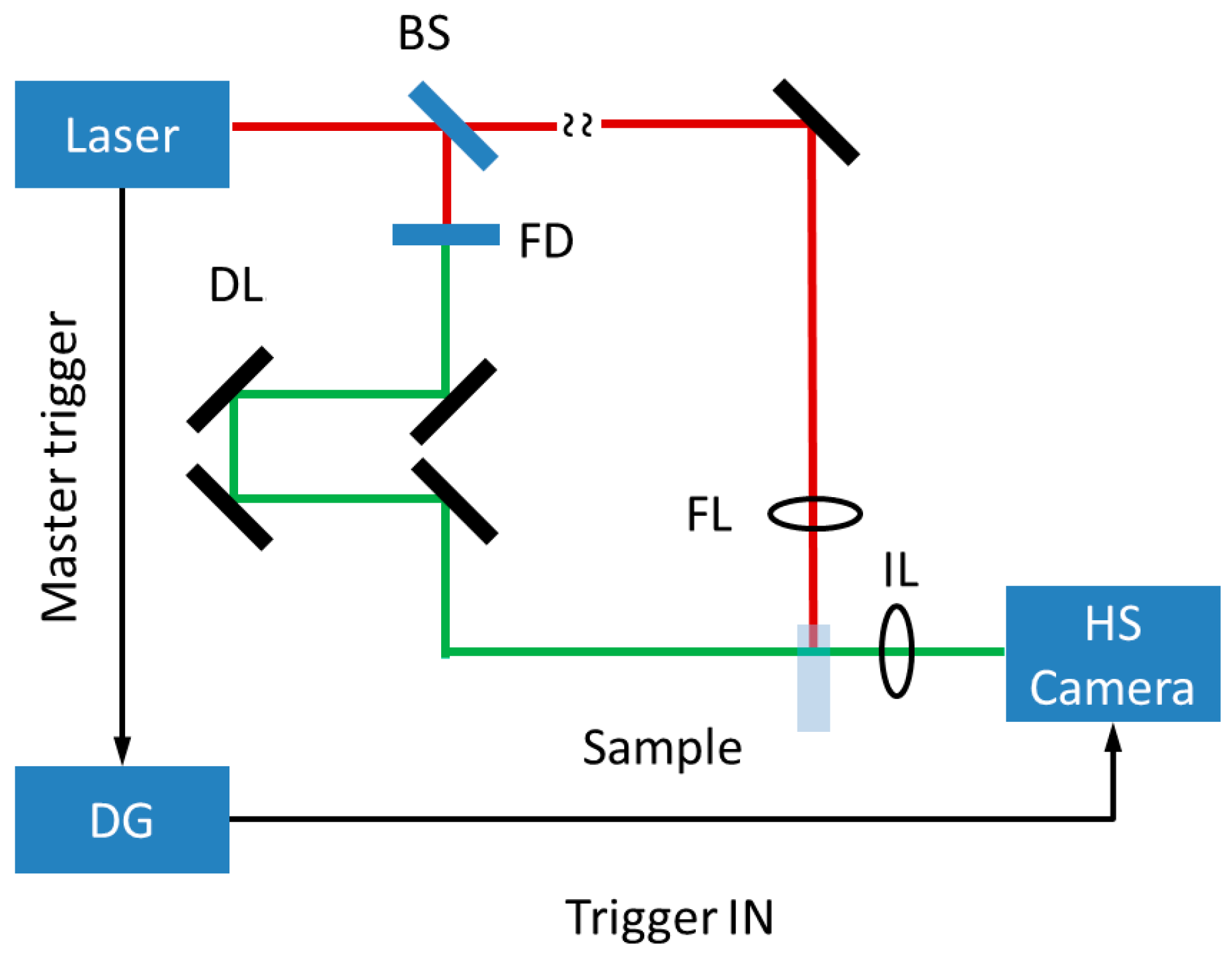
The experimental setup is schematically shown in
Figure 1 and described below. The laser beam emitted by a Nd:YVO
4 laser (Fuego, Time Bandwidth Products, Zurich, Switzerland), with nominal specifications of 1064 nm wavelength, 12 ps pulse duration, 200 kHz–8.2 MHz pulse repetition rate, and up to 50 W average power, is split using an adjustable waveplate-polarizer combination into two beam arms—pump and probe. The pump beam is focused into a test sample using a lens appropriate for the process under investigation. For the presented studies the samples were glass (D263 borosilicate glass) and polymethyl methacrylate (PMMA) slides with one edge facet polished to the optical quality. The pump beam is focused into the bulk material through that facet. The test sample is mounted on a motorized X-Y linear stage (Aerotech, Pittsburgh, PA, USA) that allows sample translation with respect to the stationary pump and probe beams at predefined speed if needed.
The probe beam is frequency doubled to 532 nm first, and then diverted into a variable length delay line. The doubling process allows us not only to simplify the setup alignment procedure but also to easily separate the pump and the probe light later on using appropriate filters. The probe delay line is built using a motorized 1-m-long linear translation stage (Zaber Technologies, Vancouver, Canada) in a double-pass configuration, allowing us to achieve pump-probe delays of −0–6 ns. The variable optical delay line is introduced to precisely determine the probe lag and to have an option of observing the interaction process at various pump-probe delays. Although, in this work the authors were primarily interested in the investigation of long-term accumulative effects and kept the probe lag constant at 3 ns. After expanding the probe beam by a factor of three, it is directed through the test sample orthogonally to the pump beam, overfilling and uniformly illuminating the interaction zone while propagating further to the recording camera. Accordingly, the diagnostic temporal resolution becomes set by the probe pulse duration (12 ps) minimizing the spatial image blurring due to the pulse shortness.
Figure 1.
Setup of the high speed (HS) pump-probe experiment. The laser beam (12 ps pulse duration) is divided into two arms using a waveplate-polarizer combination (BS). The pump beam is focused into the sample through the polished edge facet using the focusing lens FL. The probe beam is frequency-doubled (FD) and delayed (3 ns) with respect to the pump pulse in the delay line DL. It is spatially magnified (not shown) to ensure uniform illumination of the interaction volume which is imaged using the 12X zoom Navitar lens with the 2X standard adapter (the combination is denoted as IL) and the Phantom v1210 FAST high speed (HS) camera. The sample is mounted on the motorized X-Y linear stage (not shown). The laser gives Trigger OUT (master trigger) signals at the pulse repetition frequency that are used for camera synchronization via the delay generator (DG).
The interaction region was imaged using a Navitar 12X zoom objective in combination with a standard 2X adapter (Navitar, Inc., Rochester, NY, USA) mounted on a high speed camera Phantom v1210 FAST (Vision Research, Wayne, NJ, USA). The camera is electronically triggered by the laser source (master), and the short exposure time (>500 ns), shorter than the inter-laser pulse temporal separation, ensures that each recorded frame receives only one probe pulse. Depending on the resolution, the camera frame rate can be as high as 820,000 frames per second (fps), broadly overlapping with the pulse repetition rate of the laser (200 kHz–8 MHz) and the material processing regimes of interest. The recording time depends on the installed camera RAM, but even for the smallest memory option (24 GB) it exceeds 1 s at any possible resolution setting [
15], which is more than sufficient for the observation of various interaction effects. Although the nominal camera frame rate is very high (820,000 fps), the actual speed that can be achieved in an experiment becomes rather limited by the usable field of view. Depending on the set magnification of the objective-adapter combination, which can vary in the range 1.16–14 (numerical aperture
NA 0.019–0.101) [
16], the system can be either detector- or optics-limited. The camera has a relatively large pixel size of 28 μm and in order to achieve high spatial resolution the magnification should be set very close to its maximum value (
Mmax = 14). The Rayleigh criterion at the highest magnification setting is estimated at 3.2 μm, making the system optics-limited. For the highest frame rate the camera resolution is reduced to 128 × 16 pixels, providing a very small field of view: 256 μm × 32 μm at
Mmax. For some processes such a spatial window is too small, and larger camera resolution will be required. For example, in the case of glass welding the size of the zone affected by the interaction process in the longitudinal direction is on the order of 100–150 μm [
13], which effectively excludes operation at the highest frame rates. If the field of view is made square with 128 × 128 pixels, or approximately 256 μm × 256 μm at the highest magnification, then the maximum frame rate reduces to 240,000 fps. The resolution of 128 × 128 pixels and the corresponding field of view appears to be a reasonable compromise between the camera frame rate and the field of view and is suitable for the observation of many interaction processes in transparent media. As a result, the selected settings will allow the observation of every interaction event as long as the laser pulse repetition rate does not exceed 240 kHz. While these regimes are of interest, there are a number of applications where the pulse frequency should be significantly higher, such as in the case of glass welding where
fpulse > 0.5 MHz [
17]. Then, the experimental setup can be modified by adding an electronic pulse divider between the laser sources and the camera. For example, if a 2:1 pulse divider is introduced, then processes with
fpulse < 480 kHz can be recorded with every other image being skipped. Such an approach can be easily justifiable if the characteristic time of the process under investigation is much longer than the reciprocal of the camera frame rate. For the already mentioned glass welding process, the characteristic time for bubble formation and collapse is on the order of 1 ms [
13], which greatly exceeds the frame interval of 4.17 μs at 240,000 fps.
3. Experimental Results and Discussion
To demonstrate imaging capabilities of the high speed pump-probe setup, two exemplary experimental investigations have been performed. In the first experiment, the laser parameters were set to the following: 450 kHz pulse repetition rate at 3.3 W of average laser power. The pump beam was spatially magnified to slightly overfill a
NA 0.51 aspheric focusing lens (corresponding to a nominal focal spot size of 3 μm in diameter) and the beam focus was positioned approximately 200 μm deep inside the D263 glass slide that was translated with feed rate of 2–200 mm/s. The laser parameters were selected to be consistent with the ultrafast laser glass welding process [
17], and the depth of 200 μm was chosen to ensure that the interaction zone remains completely inside the glass volume while keeping the spherical aberration at a relatively low level [
18]. The camera resolution was set at 128 × 128 pixels, and the lens magnification was set at the maximum. The video recording was performed at 225,000 frames per setting—exactly half of the laser pulse repetition rate.
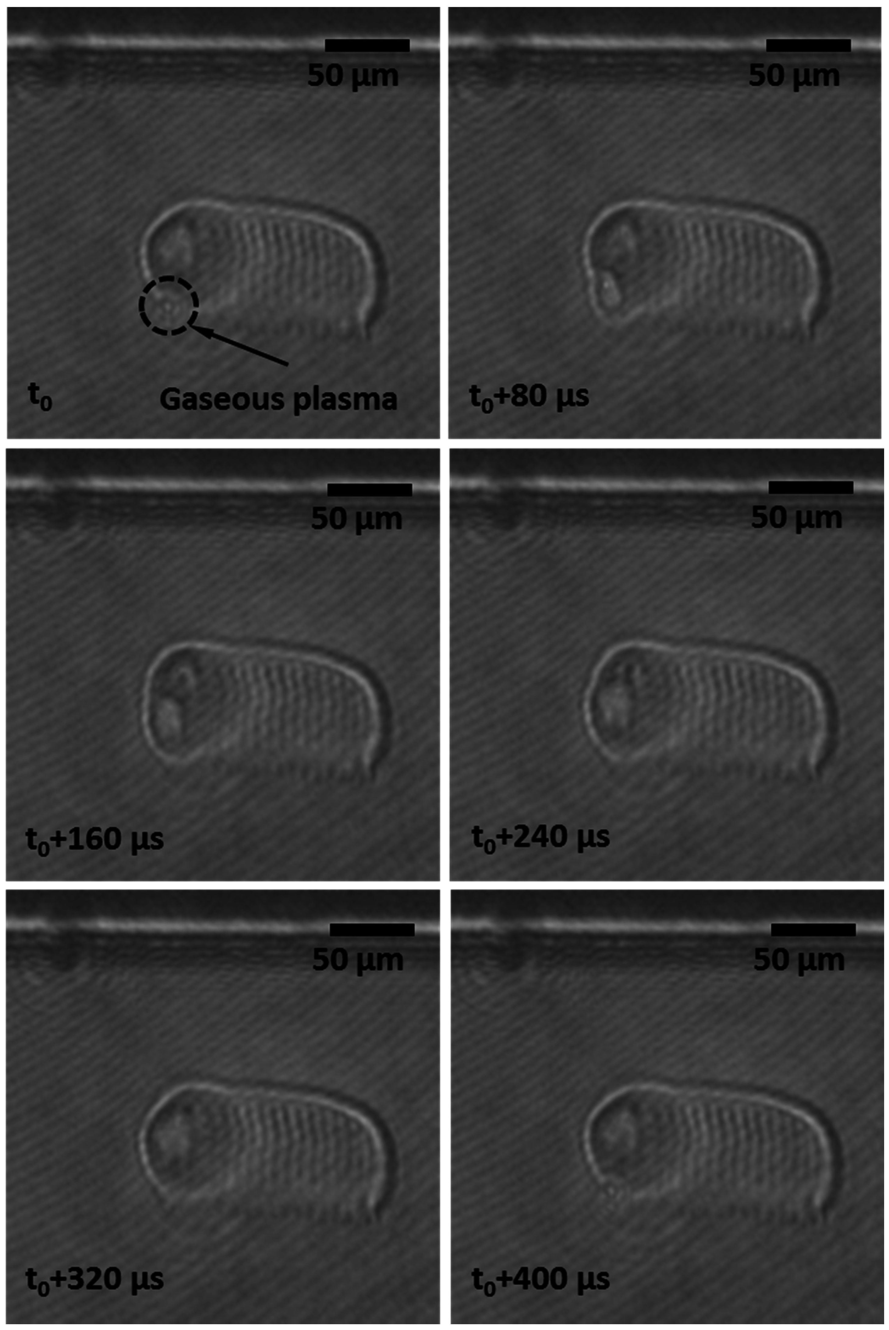
Figure 2 shows a sequence of images taken over a time interval of approximately 400 μs in equidistant time steps of 80 μs, while the complete video can be found in Video S1. Such a time interval was chosen to demonstrate a complete cycle of the plasma dynamics in the molten material, including gaseous plasma volume formation, growth, and collapse, while the sample is being translated at speed
Vfeed = 20 mm/s.
The dynamics of the gaseous plasma appear to be highly periodic, resulting in formation of a grating-like structure clearly seen in the images. The spatial period of the striation pattern matches the duration of the plasma cycle, which spans over tens of laser pulses, confirming that the origin of the periodic structures should be attributed to the gaseous plasma dynamics. The other observation that supports this theory is that the striations do not extend over the full longitudinal length of the molten zone. They terminate at the point where the gaseous plasma cavity collapse is observed, being slightly below the border of the molten pool. The border appears in the images as a whitish line at the top of the interaction volume. It is interesting to point out that the periodicity of the striations can be controlled via changing the feed rate. Although the plasma dynamic cycle shortens as the feed rate increases, it does not scale proportionally, resulting in an increased spatial period of the striations. The shortening of the temporal period is caused by the longitudinal compression of the molten zone as the feed rate rises. If in the shown images (
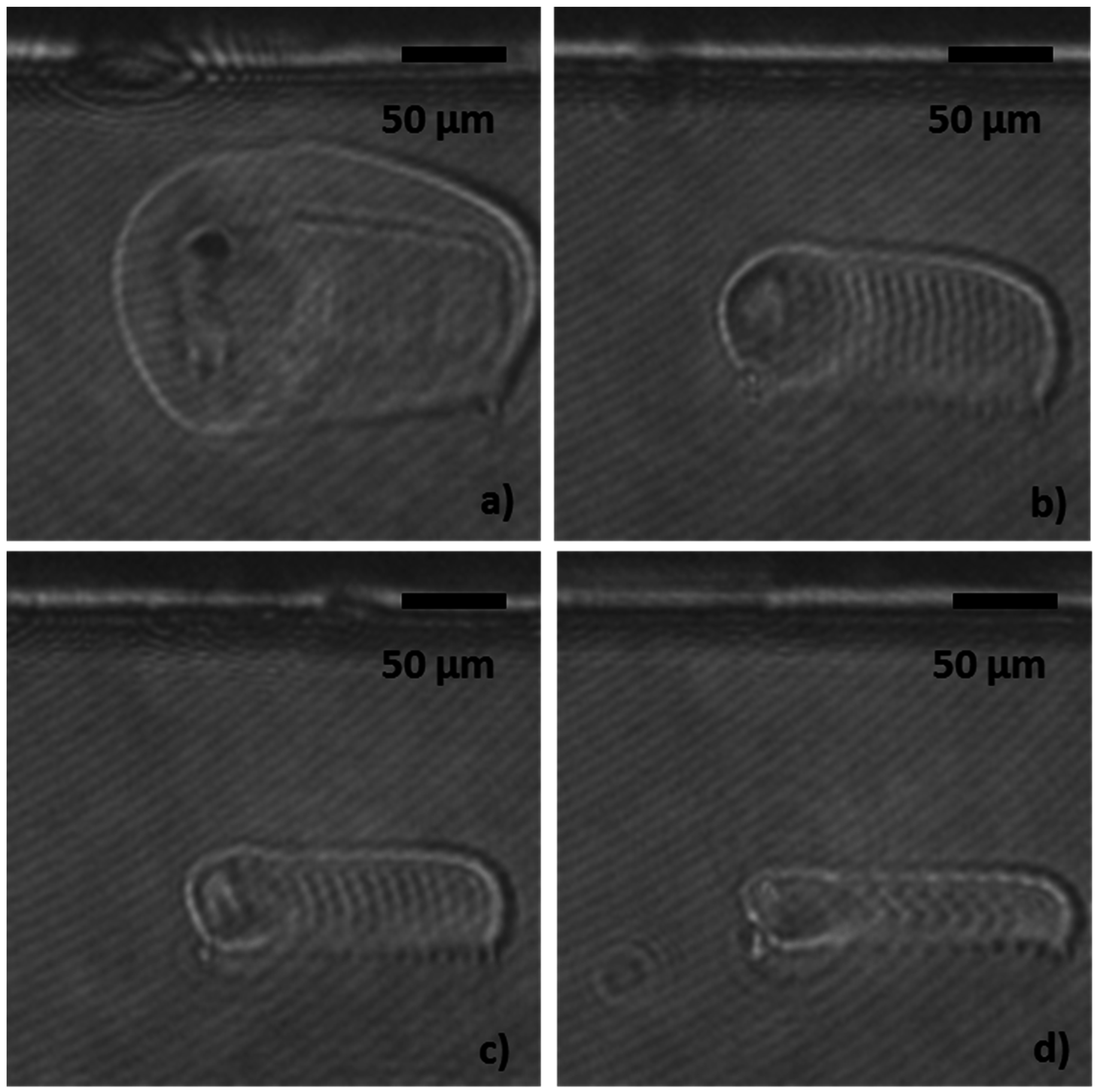
Figure 2) the spatial period is 8 μm, it becomes 11.5 μm and 15.1 μm for feed rates of 50 and 100 mm/s, respectively. Eventually, if the feed rate becomes too high, the entire gaseous plasma volume development occurs almost at a constant depth, effectively suppressing formation of the spatial periodic pattern. On the other hand, if the feed rate becomes too slow, the striations begin to merge, erasing the spatial periodicity. For the given set of laser parameters and the sample speed of 2 mm/s, the striations become completely merged, creating an almost uniform molten zone. The described effect of the feed rate on the striation pattern is shown in
Figure 3.
Figure 2.
A sequence of images taken with the high speed camera showing gaseous plasma region formation, growth, and collapse, as well as formation of the next one. Periodic striations formed by the repeating plasma dynamics can be clearly seen in the images. Process parameters: 450 kHz laser pulse repetition rate, 3.3 W average power, 20 mm/s feed rate. The laser beam propagation direction is from the top to bottom. See Video S1.
Figure 3.
A sequence of images taken with the high speed camera showing variation of the striation period with the feed rate: (a) 2 mm/s; (b) 20 mm/s; (c) 50 mm/s; (d) 100 mm/s. The laser parameters remain constant: 450 kHz pulse repetition frequency and 3.3 W of average power. Please note appearance of the plasma collapse track in (a).
The existence of the gaseous plasma volume should be attributed to vaporization and ionization as well as chemical decomposition of the base glass material [
13]. Qualitatively, the process of plasma dynamics can be described as the following: the plasma always starts to form in the focal volume of the structuring laser beam where the intensity is the highest. While currently it is not quite clear which processes predominantly contribute to the observed uplift of the plasma, two effects may be responsible: One possible process is that, due to its high temperature, the plasma exhibits lower density compared to the surrounding melt, resulting in uplift due to its buoyancy. The second possible process is a directly laser-driven plasma shift which is caused by a more effective absorption of the incoming laser pulse into an already existing plasma at the laser-coupling side (of the plasma), resulting in higher heating rates. These, in turn, will cause higher temperatures at the coupling side of the plasma, thus providing, due to the Fermi distribution, a higher electron density localized at this place. As a result, the absorption and plasma generation process may repeat itself closer to the laser source (“upstream” along the laser beam) for the next incoming pulse. In either case, the laser beam intensity in the focus is getting reduced, apparently dropping below the multi-photon ionization threshold since the generation of new plasma is temporarily suppressed. At the same time, the density of free electrons in the already existing gaseous plasma is sufficiently high, so the plasma can be heated by Joule heating and avalanche ionization and expand in spite of the laser intensity being ( at these z-positions) below the threshold for multiphoton ionization. As the plasma grows and spatially decouples from the laser beam, the electron recombination rates start to surpass the ionization rates, leading to plasma cooling. After reaching its maximum size, the gaseous plasma begins to collapse due to the high pressure from the surrounding melt. At some conditions a small residual void at the top of the periodic structure is left and can be observed (
Figure 3a). The striations are formed as plasma pressure induces density changes in the already solidifying trailing edge of the melt pool. The plasma collapse allows the laser beam to penetrate further and to reach its focus, starting a new plasma cycle and creating a tip-like structure at the bottom of the molten zone. The described behavior became more apparent when the probe pulse was blocked and the camera was imaging only the recombination emission from the gaseous plasma. Here, the camera exposure time was set to 970 ns. The recombination emission appears to follow the same temporal periodicity as the gaseous plasma and spatially oscillates in the longitudinal direction (
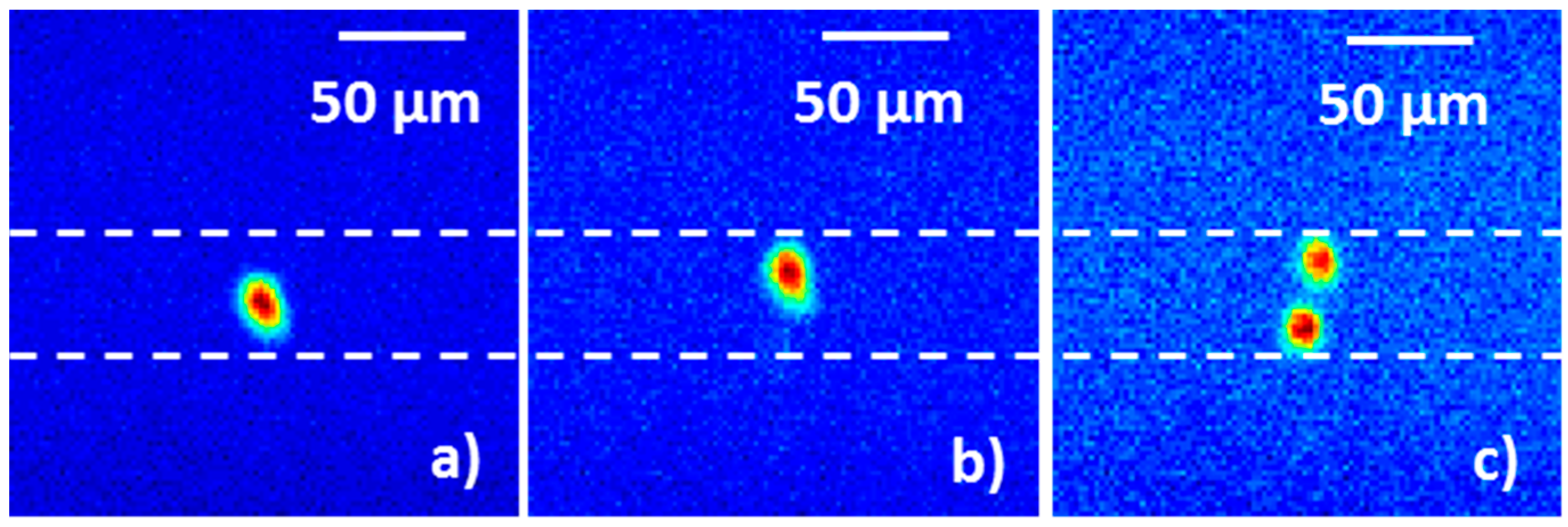
Figure 4 Vfeed = 50 mm/s) as well.
Figure 4c appears to be especially interesting since it shows two plasma regions. The top one is the hot gaseous plasma that starts to cool down and collapse while the lower one is the volume where the laser energy is currently being absorbed. Based on those images it can be clearly seen that the plasma is not always present in the nominal laser focus, which confirms that the laser energy absorption does not occur at the same depth all the time.
Figure 4.
Images of recombination plasma emission (gray-scale images were converted to false color images for better clarity) show spatial displacement of the plasma region. Image (
b) is delayed 98 μs with respect to (
a) and image (
c) is delayed 53 μs with respect to (b). Displacement of the plasma region appears to be smaller compared to the longitudinal extend of the striation pattern or the molten zone (compare to
Figure 3c). Process parameters: 450 kHz pulse frequency, 3.3 W average power,
Vfeed = 50 mm/s. The white lines are visual aids only, and the laser beam propagation direction is from top to bottom.
In the second experiment that was performed to investigate the capabilities of the high speed pump-probe apparatus, the laser settings were adjusted to a 200 kHz pulse repetition rate and 25.4 W of average laser power. The expanded pump beam (7.2 mm in diameter at 1/
e2 intensity level) was focused using a 100 mm focal length lens (nominal focal spot diameter is 23 μm) into the PMMA sample translated at
Vfeed = 100 mm/s. Here, the process parameters were adjusted to be consistent with the polymer ultrafast laser cutting processes [
19]. The relatively low laser repetition frequency allowed process recording at the matching frame rate of 200,000 fps, and with an increased resolution of 256 × 128 pixels. The spatial magnification was set to
M = 12.6, resulting in the field of view 570 μm × 285 μm.
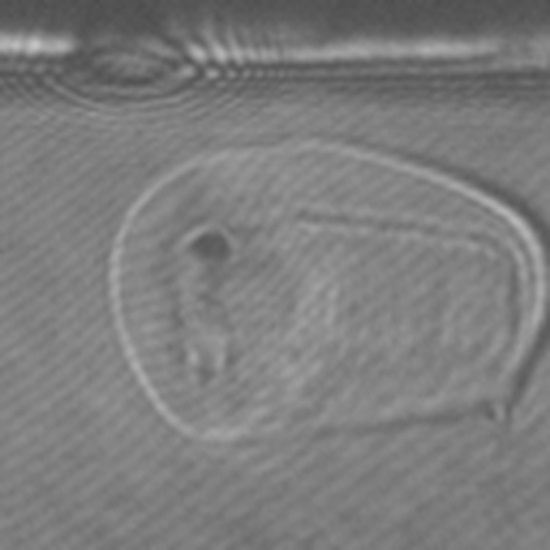
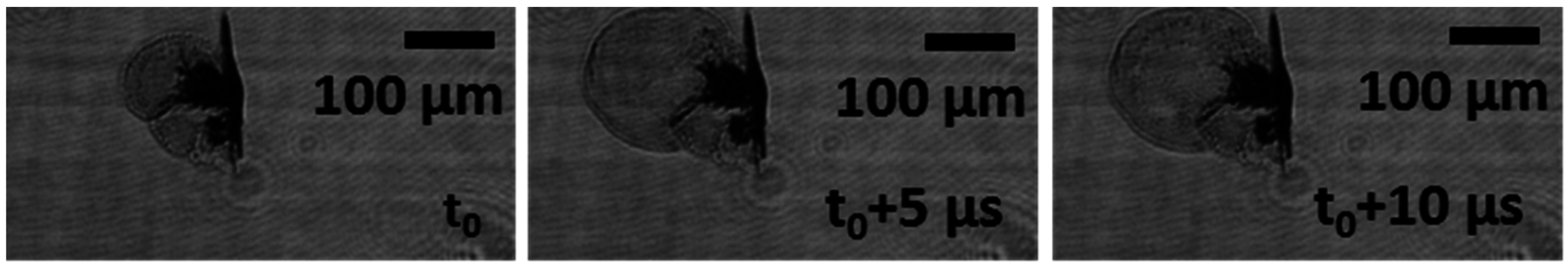
Figure 5 shows three sequential snapshots separated by 5 μs that captured the growth and explosion of a void created by ultrafast laser pulses in the PMMA sample. Please note that the affected volume is significantly larger than the laser interaction zone. Complete video of the interaction process can be found in Video S2. In general, the interaction process in PMMA appears to be very stochastic and more dynamic compared to glass. A reason for such behavior can be attributed to the shortening of the polymer chains to methyl methacrylate as well as further chemical decomposition of PMMA. The formed liquid and gaseous phases that are easily seen in the video are likely to be under extremely high pressure, promoting the rapid formation of internal cracks. Such dynamic behavior can be difficult to deduce from the subsequent microscopic analysis, but can be easily observed with the high speed pump-probe setup. Such visual observations can be used for process optimization as a function of machining parameters, for example in ultrafast cutting and structuring of PMMA-like materials.
Figure 5.
Sequential images of the PMMA ultrafast laser interaction process. The frame temporal separation is 5 μs. Process parameters: 200 kHz pulse frequency, 25.4 W average power, Vfeed = 100 mm/s. Explosion-like expansion of the intra-material crack can be easily seen in the second frame, which is getting filled with the liquid and gaseous phases seen in the third image. See Video S2.


