Article

Mixing Analysis of Passive Micromixer with Unbalanced Three-Split Rhombic Sub-Channels

Department of Mechanical Engineering, Inha University, Incheon 402-751, Korea
*
Author to whom correspondence should be addressed.
Micromachines 2014, 5(4), 913-928; https://doi.org/10.3390/mi5040913
Submission received: 15 September 2014 / Revised: 3 October 2014 / Accepted: 10 October 2014 / Published: 22 October 2014
(This article belongs to the Special Issue Micromixer & Micromixing)

Abstract

:
A micromixer with unbalanced three-split rhombic sub-channels was proposed, and analyses of the mixing and flow characteristics of this micromixer were performed in this work. Three-dimensional Navier-Stokes equations in combination with an advection-diffusion model with two working fluids (water and ethanol) were solved for the analysis. The mixing index and pressure drop were evaluated and compared to those of a two-split micromixer for a range of Reynolds numbers from 0.1–120. The results indicate that the proposed three-split micromixer is efficient in mixing for a range of Reynolds numbers from 30–80. A parametric study was performed to determine the effects of the rhombic angle and sub-channel width ratio on mixing and pressure drop. Except at the lowest Reynolds number, a rhombic angle of 90° gave the best mixing performance. The three-split micromixer with minimum minor sub-channel widths provided the best mixing performance.

1. Introduction

In recent years, lab-on-a-chip (LOC) is a rapidly rising research topic within the instrumentation and healthcare industries. A LOC combines and miniaturizes many technologies for applications in a wide range of disciplines including chemical analysis [1], clinical and forensic analysis [2], DNA sequencing [3], and bio-analytical systems analysis [4]. A microfluidic device deals with the precise control and manipulation of fluids that are geometrically constrained to a small (typically sub-millimeter) scale. In micro systems, fluid mixing becomes very difficult because of the tiny sizes involved. To obtain the required mixing, traditional methods for stirring fluids are not applicable. Due to the small sizes of micromixers, the flow is inevitably laminar. In microfluidic devices, mixing mainly depends on molecular diffusion, which is usually a very slow process. Therefore, in many applications, it is necessary to use appropriately designed micromixers to enhance mixing.
Mixing in microchannels plays an important role in microelectromechanical systems (MEMS) and micro-total analysis systems [5]. Micromixers reported in the literature can be classified into two categories, active and passive mixers, depending on their mixing principal [6]. Active micromixers involve external forces. Mixing can be enhanced by stirring the flow in order to establish secondary flows [7]. This stirring effect can be achieved by using additional structures or external sources including ultrasonic vibration, electric fields [8], dielectrophoresis, electro-hydrodynamic, electroosmosis, magnetic forces [9], and bubble-induced acoustic micro streaming [10]. The secondary flow stretches and folds the interface of the fluids, thereby reducing the diffusion path between the fluid streams and increasing the mixing phenomenon. However, the fabrication of this type of microfluidic mixer is rather complex. Furthermore, these devices generally require some type of external power source and a control system, and they are difficult to operate, clean, and integrate into microfluidic systems. On the other hand, passive micromixers do not require any external source of energy except for driving the fluid flow. Thus, mixing is promoted only by modifying the microchannel geometry. A passive mixer reduces the diffusion path between the fluid streams by splitting and recombining the flow [11]. Due to their simplicity, passive mixers are being used in most microfluidic applications instead of active mixers.
Passive mixers can be further classified as lamination or injection micromixers. In lamination mixers, the fluid streams are separated into several small streams that are later connected in a mixing channel [12]. On the other hand, an injection mixer splits only one stream into many sub-streams, which increases the contact surface and reduces the mixing path [7].
Over the past decade, several experimental and numerical studies have been carried out for different passive micromixers. Various investigations have been performed to characterize the mixing of fluids based on the analysis of laminar flow and mixing in passive micromixers such as T mixers, Y mixers, different types of serpentine micromixers [13,14], micromixers with patterned grooves [15,16,17], and split and recombine (SAR) micromixers [18,19,20,21]. Numerical and experimental studies were performed by Fang and Yang [22] on a three-dimensional (3-D) rotating microfluidic device with a range of Reynolds numbers from 0.01–100. Their study demonstrated that the mixing mechanism based on SAR creates chaotic advection and shows better performance for relatively high Reynolds numbers. Vladimir and Nimafar [19] introduced a novel 3-D SAR passive micromixer called the “chain micromixer”. Experimental verification and numerical analysis of the flow structure were performed in a low Reynolds number range, 0.083 ≤ Re ≤ 4.166. The experimental results showed that the mixer’s efficiency reached 98% due to the SAR process. Their previous study [20] on an H-shaped micromixer based on the SAR process demonstrated that the efficiency of this micromixer is very high at a low Reynolds number (Re = 0.083) due to the SAR behavior. Schönfeld et al. [23] conducted a numerical investigation of an SAR micromixer, and their investigation over a wide range of Reynolds numbers illustrated that the SAR mixer provided efficient mixing.
Based on the mentioned studies, it is clear that a passive SAR micromixer, wherein the main channel is divided into two sub-channels and the sub-channels recombine after a certain distance in a repetitive fashion, is very effective in enhancing the mixing of fluids. The performances of circular and rhombic SAR micromixers were compared numerically by Ansari and Kim [24]. A numerical and experimental study on an SAR-based rhombic micromixer was studied by Chung and Shih [25,26]. They compared the performances of rhombic micromixers with and without constriction at the recombine section. The interface of fluids was strongly distorted by the constrictions; hence, mixing was remarkably enhanced. However, the use of flow constrictions requires higher pumping power due to the high pressure drop. Unbalanced splits and cross-collisions of fluid streams were investigated numerically and experimentally by Ansari et al. [27]. Their results demonstrate that mixing performance is maximized when the width of the major sub-channel is twice that of the minor sub-channel, and the lowest mixing performance is obtained for equal sub-channel widths. Thus, the unbalanced SAR is effective in mixing compared to the balanced SAR.
In this study, a micromixer with three unbalanced rhombic sub-channels was proposed, and numerical analyses were performed to investigate the mixing behavior and flow characteristics of this micromixer in comparison with a micromixer with two-split rhombic sub-channels. 3-D Navier-Stokes equations were solved for a mixing analysis using two working fluids: water and ethanol. The mixing performance and pressure drop were analyzed with two geometric parameters, the rhombic angle and sub-channel width ratio, for Reynolds numbers from 0.1–120.

2. Micromixer Models

Schematic diagrams of the SAR-based unbalanced two-split and three-split rhombic micromixers are shown in Figure 1. The two fluids enter through two different inlets, respectively, and come into contact at a T-joint where they undergo some mixing before entering a series of sub-channels. Figure 1a shows the two-split micromixer, where the main channel is split into two sub-channels of unequal widths, and the sub-channels are recombined in a repetitive way. The widths of the two sub-channels w1 and w2 are 200 μm and 100 μm, respectively. The sum of the widths of the two sub-channels is equal to the width of the main channel; w1 + w2 = w = 300 μm. The major sub-channel changes its position after each collision along the x-axis.
Figure 1b shows the proposed SAR-based modified rhombic micromixer with unbalanced three-split sub-channels. To compare the mixing performance of the unbalanced three-split rhombic micromixer with unbalanced two-split rhombic micromixer, the main channel (w) was divided into three sub-channels. The two micromixers (Figure 1a,b) are comprised of four split and recombination segments. The height of the micromixer, h, for both of the cases was kept constant at 900 μm. The dimensions of the reference model of the three-split micromixer are as follows. The width of the major sub-channel (w1) is 200 μm. The minor sub-channel (w2) is divided into two equal widths, w21 = 50 μm and w22 = 50 μm. The sum of the widths of the three sub-channels is equal to the width of the main channel: w1 + w21 + w22 = w = 300 μm. The pitch, Pi is the same in both micromixers, 1.2 mm. The rhombic angle is 90°. The axial lengths of the inlet and exit parts of the main channel shown in Figure 1 are Lo = 475 μm and Le = 3 mm.
In this work, a parametric study of the unbalanced three-split rhombic micromixer was performed to improve the mixing performance with respect to two geometric parameters. Two dimensionless parameters, the ratio of the minor sub-channel 1 width (w21) to the major sub-channel width (w1), and the rhombic angle (θ), were selected in order to determine their effects on mixing performance and pressure drop. The value of the dimensionless parameters w21/w1 and θ were varied from 0.25–4 and 50°–110°, respectively. In cases of changing sub-channel widths, the widths of the sub-channels were controlled by changing the position of the outer wall with respect to the fixed inner wall. The total number of rhombic units, the height of the inside rhombic shape (h), and the sub-channel widths were kept constant when changes were made to angle θ.
Figure 1. Schematic diagrams of rhombic micromixers: (a) unbalanced two-split rhombic micromixer, and (b) unbalanced three-split rhombic micromixer.
Micromachines 05 00913 g001

3. Numerical Analysis

To analyze the flow phenomena and mixing behavior of the fluids in the SAR-based unbalanced multi-split rhombic micromixers, the commercial computational fluid dynamics (CFD) code ANSYS CFX-12.1 [28] was used. This code solves the mass and momentum (Navier-Stokes) conservation equations by using a finite volume approximation, and is capable of modeling fluid mixtures that comprise many separate physical components, each component can have a distinct set of physical properties. The solver calculates the appropriate average values of the properties for each control volume in the flow to compute the fluid flow. The bulk motion of the fluid was modeled using single flow parameters (such as velocity, pressure, etc.). Each component had its own equation for the conservation of mass, as follows:
( ρ i V j ) x j =   x j ( ρ i ( V i j V j )
V j =   ρ i V i j ρ ¯
ρ i ( V i j V j ) = Г i ρ ¯ ρ i x j
where ρi is the density of fluid component i in the mixture, ρ ¯ is the average density of the mixture, ρi(Vij − Vj) is the relative mass flux, Vij is the velocity of fluid component i, and Vj is the average velocity of the mixture. In the mixture, the differential motion of the distinct components is accounted for by the relative mass flux term. This term can be expressed in a number of ways to include the effects of concentration gradients, pressure gradients, etc. The concentration gradient is the primary effect of the possible relative motion of the mixture components. Γi is the molecular diffusion coefficient of fluid component i, and can be expressed as follows:
Г i = ρ D i
where Di is the diffusivity of fluid component i.
An unstructured tetrahedral grid system was created using ANSYS ICEM 12.1. The quality of the mesh was examined because the computation accuracy depends on it. The numerical simulation is not free from the numerical diffusion errors that arise from the discretization of the convection terms in the Navier-Stokes equations. However, this error can be minimized by adopting a higher-order numerical scheme for the convection terms [29]. A high resolution scheme [28] was used for discretization of the convective terms in the governing equations. Furthermore, SIMPLEC algorithm [30] was used for the pressure velocity coupling. The details of the governing equations and numerical methods can be found in the previous paper [31,32]. No-slip boundary conditions were used at the solid walls. Uniform velocities were assigned at the inlets, and a zero static pressure was specified at the outlet. The Reynolds number was evaluated by considering the width of the main channel with water as the working fluid. The mixing analysis was carried out with ethanol and water entering the micromixer from Inlet 1 and Inlet 2, respectively. The present numerical study was carried out over a range of Reynolds numbers from 0.1–120. The properties of the water and ethanol were taken at 20 °C, as listed in Table 1.
To quantify and analyze the mixing behavior, the variance of the liquid species in the micromixer was calculated. The variance of the species was determined at a cross-sectional area of the micromixer perpendicular to the x-axis. The variance is based on the concept of the intensity of segregation, using the mean concentration. To evaluate the degree of mixing, the variance of the mass fraction of the mixture in a cross-section that is normal to the flow direction is defined as follows:
σ =   1 N ( c i c ¯ m ) 2
where N is the number of sampling points inside the cross section, ci is the mass fraction at sampling point i, and c ¯   m is the optimal mixing mass fraction, which is 0.5 at any cross-sectional plane. To quantitatively analyze the mixing performance of the micromixer, the mixing index at a cross-sectional plane is defined as:
M = 1 σ 2 σ max 2
where σ is the standard deviation of the concentration across the channel in a crosssection at any specific longitudinal location, and σmax is the maximum standard deviation (unmixed at the exit). A greater mixing index indicates a higher mixing quality. Thus, the value of this mixing index is zero for completely separate streams (for which σ = σmax), and unity for completely mixed streams (for which σ = 0). For all geometries, the mixing index was calculated after a single unit in order to compare the results across geometries.
Table 1. Properties of fluids at 20 °C.
FluidDensity (kg·m−3)Viscosity (kg·m−1·s−1)Diffusivity (m2·s−1)
Water9.998 × 1020.9 × 10−31.2 × 10⁻⁹
Ethanol7.890 × 1021.2 × 10−31.2 × 10⁻⁹

4. Results and Discussion

The results of a grid dependency test with six different grid systems comprised of a number of nodes ranging from 3.77 × 10⁵ to 1.72 × 10⁶ for a micromixer with unbalanced three-split rhombic sub-channels (Figure 1b) are shown in Figure 2. From the results of the test for the distribution of the mixing index, a grid system with 1.48 × 10⁶ nodes was selected as the optimum grid system for further calculations.
Figure 2. Grid dependency test for reference three-split micromixer (w1 = 0.2 mm, w21 = 0.05 mm, and w22 = 0.05 mm).
Micromachines 05 00913 g002

4.1. Comparison between Two-Split and Three-Split Micromixers

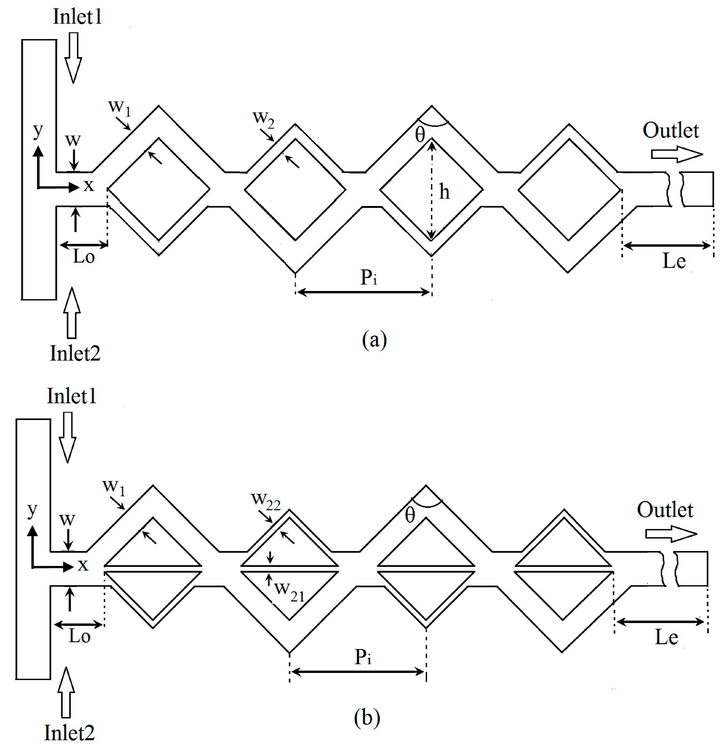
First, the performance of the reference unbalanced three-split rhombic micromixer (Figure 1b) was evaluated compared with those of the two-split micromixer (
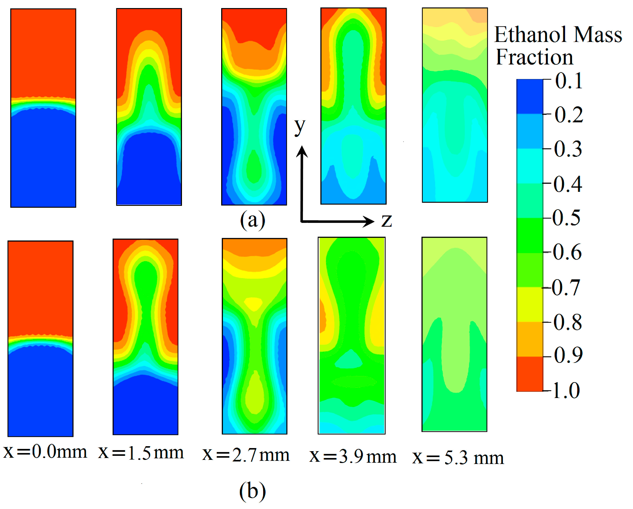
Figure 1a). Mass fraction distributions of ethanol on y-z planes at a Reynolds number of 60 are shown in Figure 3. To analyze the mixing behavior, each ethanol mass fraction distribution was plotted at the exit of each rhombic unit. At x = 0, Figure 3a,b show that the paths of the two fluids are nearly parallel to each other, and there is no secondary flow. As the flow proceeds through the channel, secondary flows are induced, and hence the mixing is enhanced. Whenever the position of a major sub-channel is reversed, an alternation of distribution occurs. At Re = 60, the values of the mixing index at the end of the fourth cell are 0.61 and 0.86 for the two-split and three-split micromixers, respectively. To find the flow structures in unbalanced two-split and three-split rhombic micromixers, velocity vectors were plotted on the x-y plane at Re = 40, as shown in 
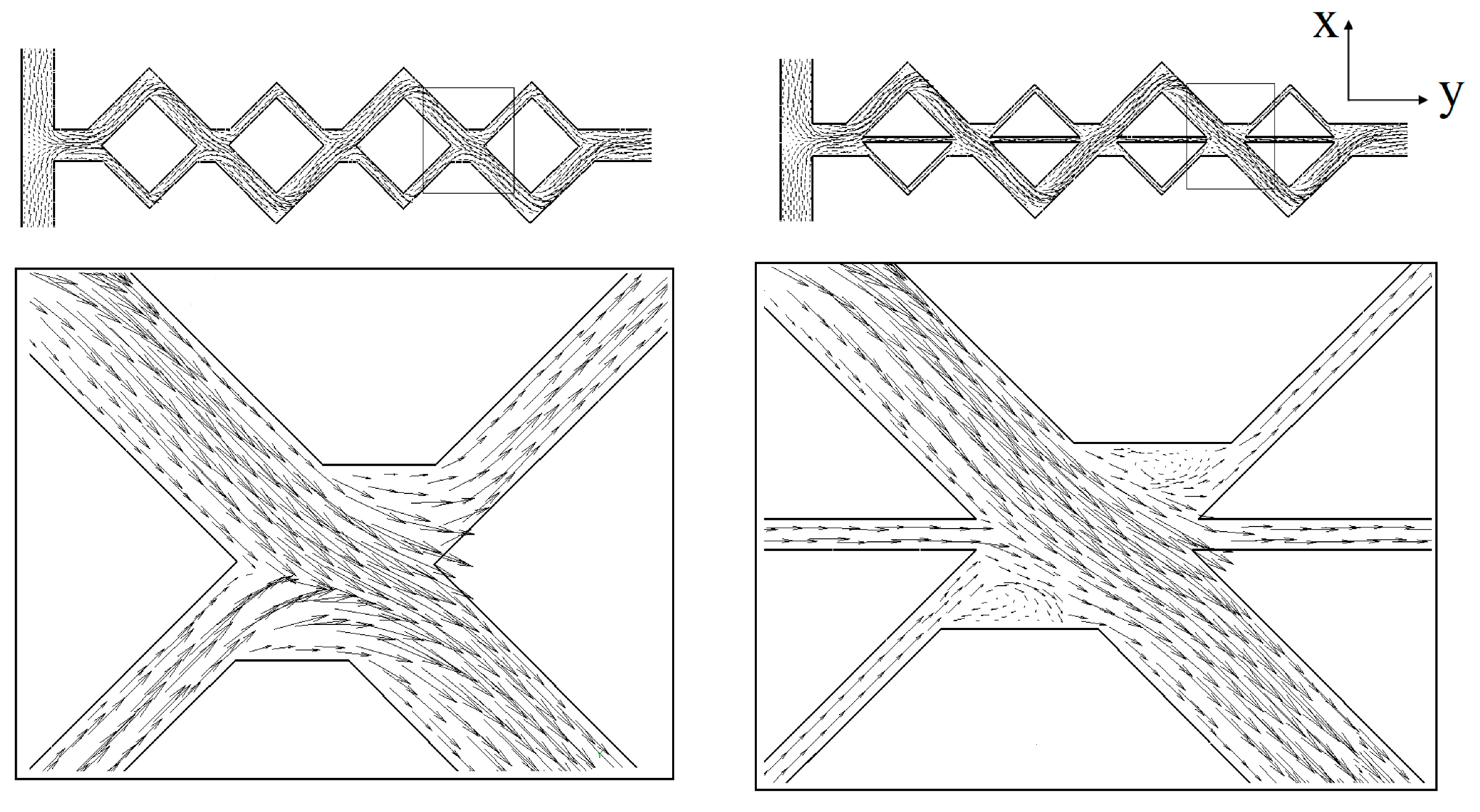
Figure 4. The flow in the main channel was divided into two or three sub-streams according to their geometries, and they collided with each other in the combination zone. The same pattern was repeated in the microchannels. The magnified images show the flow phenomena in the combination zone after the third rhombic cell. The velocity vectors are parallel to the channel wall without any transverse flow in the major sub-channel, and the flow patterns are almost the same for both micromixers. No transverse flow occurred in the two-split rhombic micromixer, while two small recirculation flows were generated in the three-split unbalanced rhombic micromixer near the inlet of the minor sub-channel. Additionally, these small recirculation flows contributed to the enhancement of mixing. 
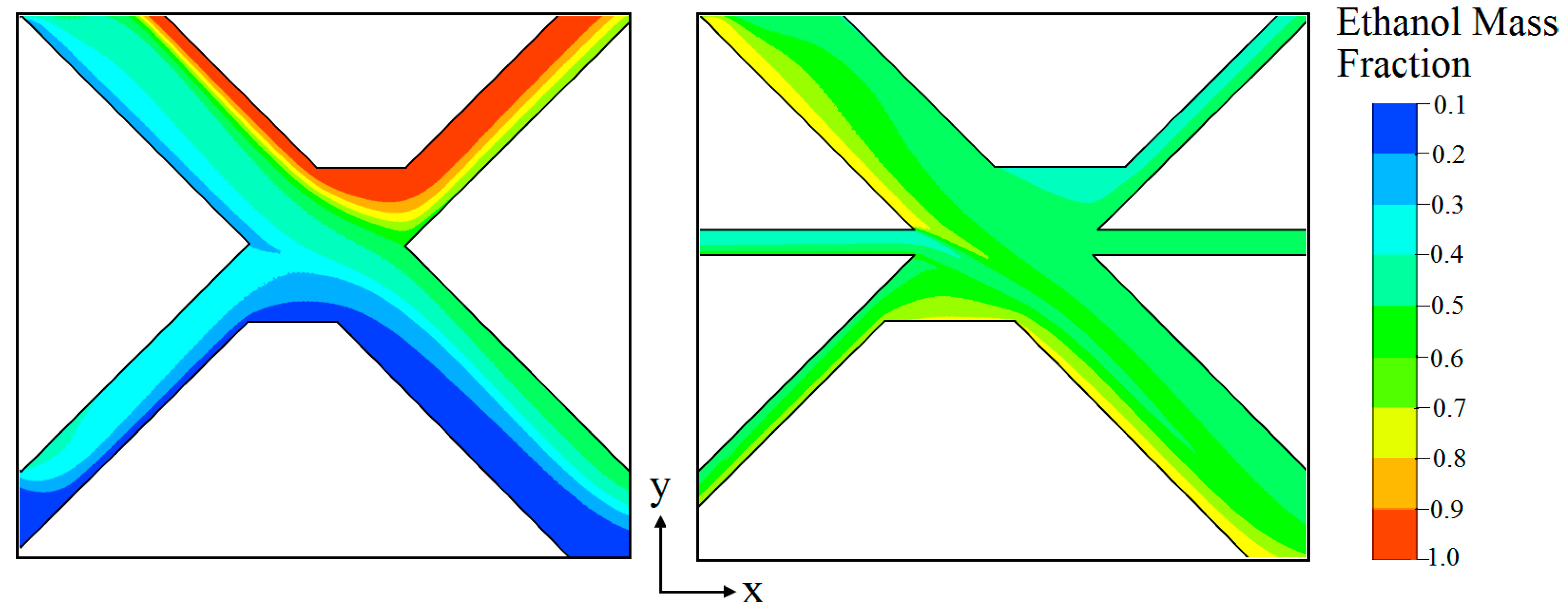
Figure 5 shows the mass fraction distributions of ethanol on the x-y plane at a Reynolds number of 40 in the same enlarged area indicated in Figure 4. The figure shows that the three-split micromixer exhibited far better mixing than the two-split micromixer in this combination zone after the third rhombic cell, especially in the two small recirculation zones indicated in Figure 4.
Figure 3. Concentration distributions of ethanol on y-z planes at various cross-sections (Re = 60): (a) two-split unbalanced rhombic micromixer, and (b) three-split unbalanced rhombic micromixer.
Micromachines 05 00913 g003
Figure 4. Velocity vector plots on x-y plane at Re = 40 in unbalanced two-split and three-split rhombic micromixers.
Micromachines 05 00913 g004
Figure 5. Concentration distributions of ethanol on the x-y plane at Re = 40 in the region indicated in Figure 4 in unbalanced two-split and three-split rhombic micromixers.
Micromachines 05 00913 g005
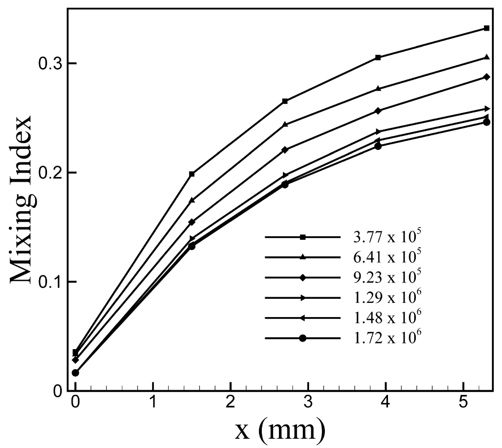
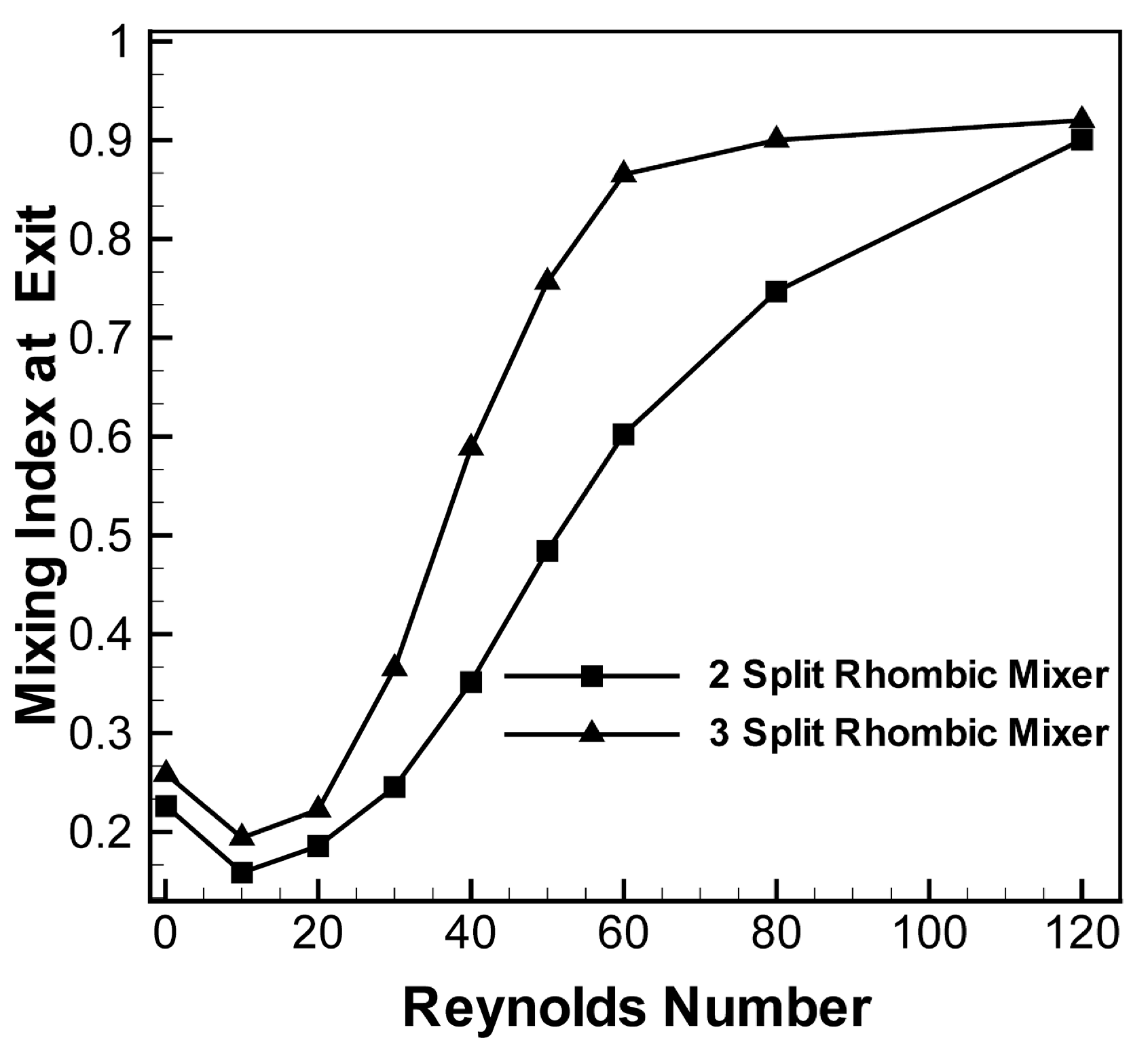
Figure 6 shows variations of the mixing index at the exit of the fourth rhombic unit (x = 5.3 mm) of the micromixer for Reynolds numbers from 0.1–120 for the unbalanced two-split and three-split rhombic micromixers with the same axial length. At low Reynolds numbers (less than 1), the mixing is mainly governed by molecular diffusion, and mechanical stirring is ineffective [33]. Thus, at a low Reynolds number, the mixing is dominated by the residence time and depends on the total path length of the flow. As the Reynolds number increased, the level of the mixing index decreased rapidly due to the decrease in the residence time, and reached its minimum at Re = 10. For this Reynolds number range, the residence time is insufficient and the transverse flow is still inactive; thus, the mixing index remained at the lower level. Thus, modification of the geometry of the micromixer is not so effective for mixing at these low Reynolds numbers. However, beyond this Reynolds number, even though the residence time decreased further, the transverse flows rapidly become active, and mixing started to increase as the Reynolds number increased. The micromixer with unbalanced three-split rhombic sub-channels showed better mixing performance throughout the intermediate Reynolds number range (less than 120). From Re = 20, the difference in the mixing index between the two micromixers starts to increase, and the maximum difference in the mixing index is found at Re = 50. Thereafter, the difference decreases and nearly disappears at Re = 120. Unlike the two-split micromixer, the three-split micromixer shows almost full development of the mixing index at Re = 60. At Reynolds numbers of 30, 40, 50, and 60, the mixing indices at the end of the unbalanced three-split rhombic micromixer are 1.49, 1.67, 1.56, and 1.44 times the corresponding mixing index of the unbalanced two-split rhombic micromixer, respectively.
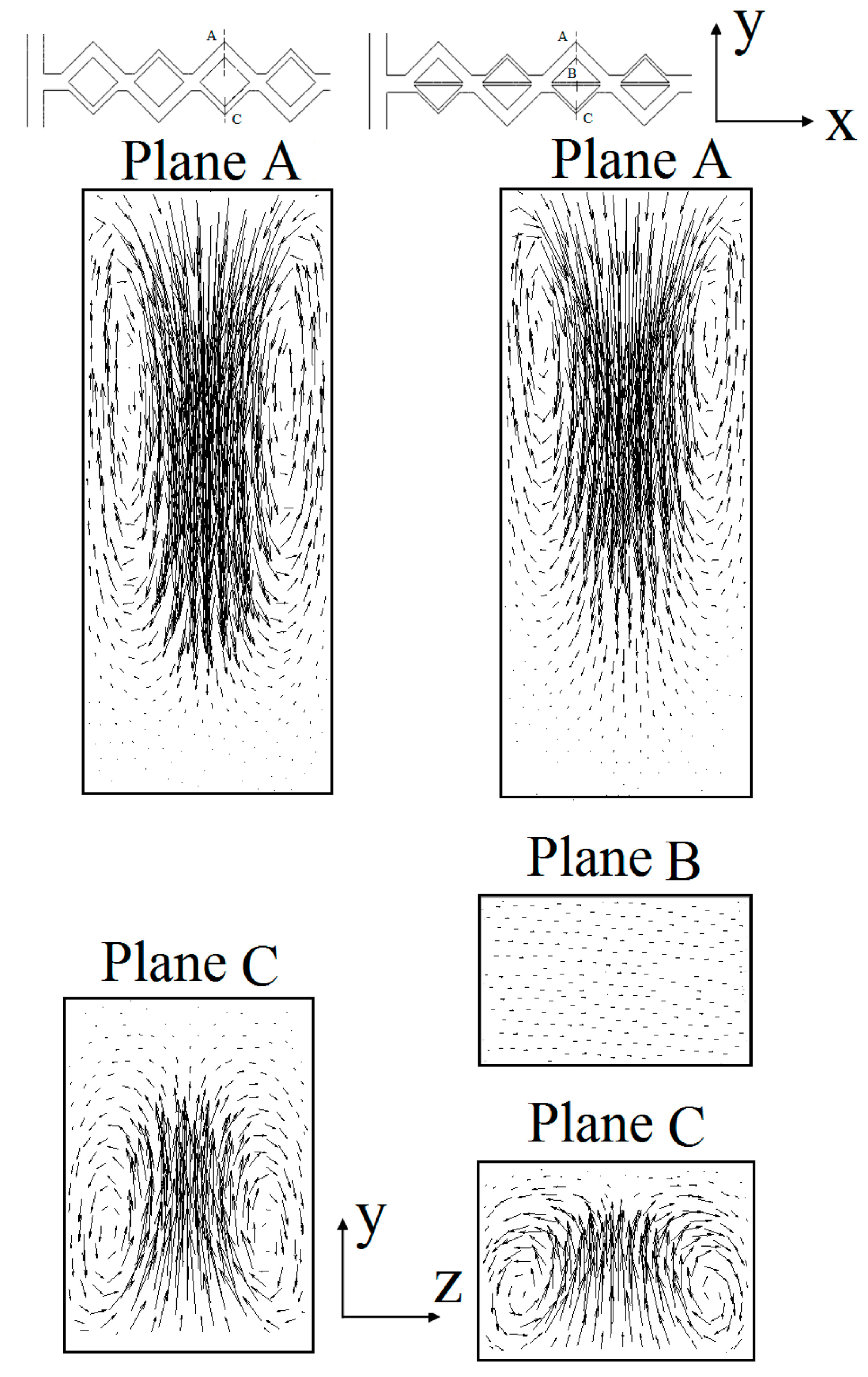
Velocity vector plots for two different rhombic micromixers at Re = 40 are shown in Figure 7. Velocity vectors were plotted on the cross sections located at tip of the third rhombic unit (planes A, B, and C). In both micromixers, two strong counter-rotating vortices were present in the major sub-channel (plan A). Compared to the micromixer with two-split sub-channels in the three-split micromixer, the center of the vortices shifted to the top of the cross-section. As a result, the velocity vectors became weak near the bottom of the plane. Velocity vectors on planes B and C represent the flow structures in the minor sub-channels. Two counter-rotating vortices were also observed in plane C in both micromixers. In the case of the three-split micromixer, two comparatively small circular-shaped vortices occupied most of the cross-sectional area of the channel, whereas in the two-split micromixer elliptical counter-rotating vortices shifted to the bottom. In the three-split micromixer, weak transverse flow occurred at plane B.
Figure 6. Variations in the mixing index at the exit of the micromixer versus Reynolds number.
Micromachines 05 00913 g006
Figure 7. Velocity vector plots on y-z planes at Re = 40 in unbalanced two-split and three-split rhombic micromixers.
Micromachines 05 00913 g007
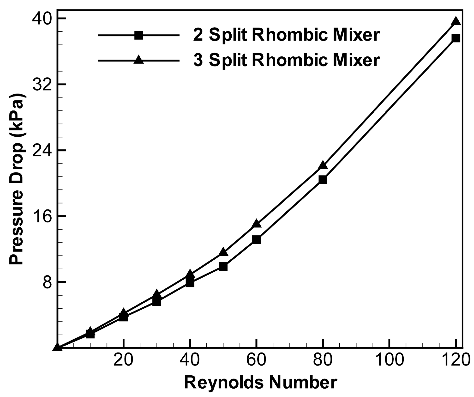
Figure 8 shows the pressure drop characteristics as a function of Reynolds number in a range of Reynolds number from 0.1–120 for both micromixers. In all cases, the pressure drop was calculated at the exit of the fourth rhombic unit (x = 5.3 mm). The pressure drop increases with the Reynolds number for both cases. At lower Reynolds numbers (less than 10), where wall friction is small and the transverse flow is inactive, the effect of micromixer geometry on pressure drop is almost negligible. Beyond this Reynolds number, the three-split micromixer shows a higher pressure drop due to the higher wall friction and stronger transverse motion, but the relative increase in the pressure drop is less than only 16.8% throughout the Re range.
Figure 8. Variations of the pressure drop with Reynolds number in unbalanced two-split and three-split rhombic micromixers.
Micromachines 05 00913 g008

4.2. Effects of Design Parameters on Mixing and Pressure Drop

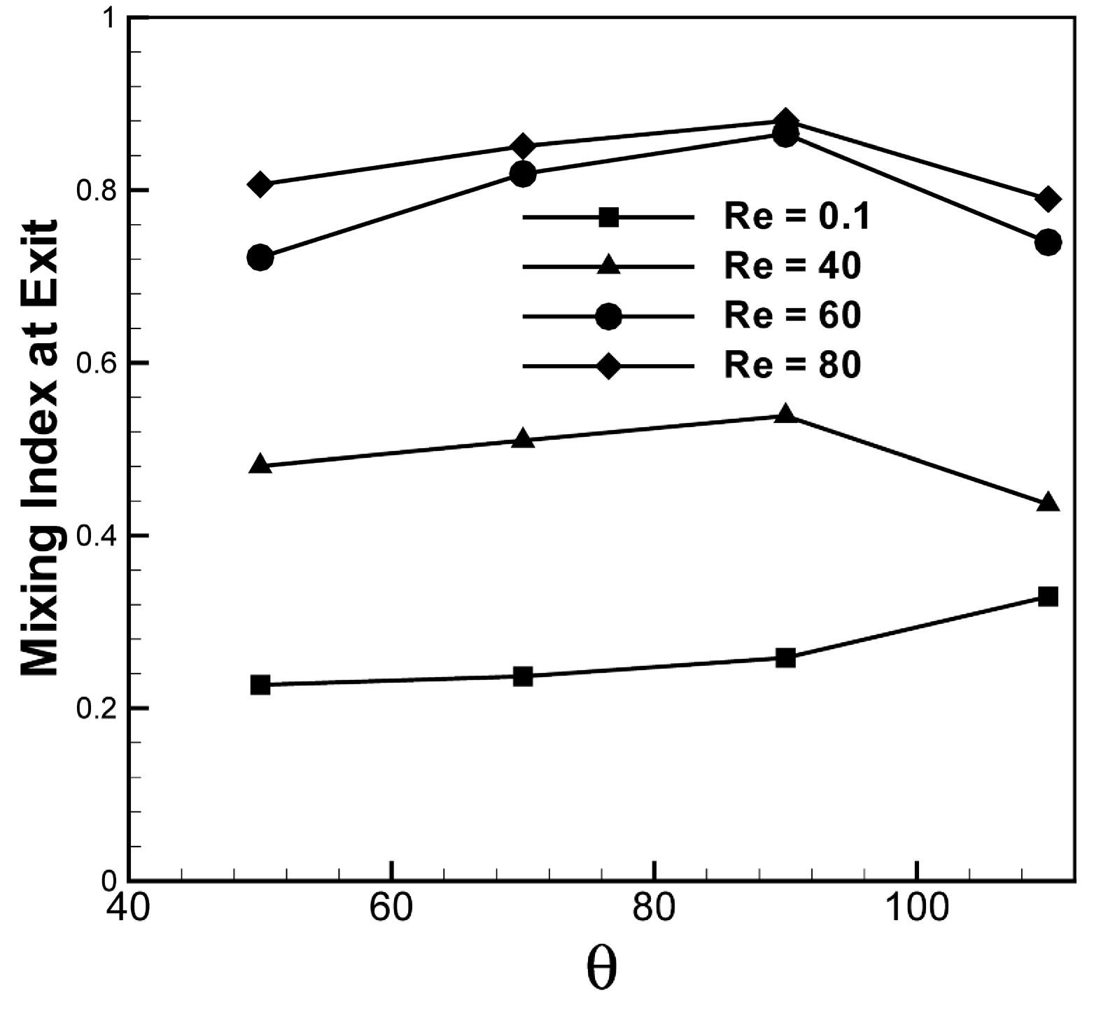
To analyze the effect of the rhombic angle (θ in Figure 1) on mixing, the variations of the mixing index at the exit of the three-split micromixer versus θ for Reynolds numbers ranging from 0.1–80 were plotted, as shown in Figure 9. The total number of rhombic units was kept constant. θ was varied from 50°–110°, and the pitch (Pi) was changed with the fixed height, h, according to the change in θ.
Figure 9 shows that the mixing index has a maximum value at 90° except for the lowest Reynolds number, Re = 0.1. At Re = 0.1, the mixing index increased as the angle increased throughout the test range of the angle. With the increase in the angle, the flow path increased, thereby resulting in an increase in residence time. This enhanced mixing at low Reynolds numbers, where mixing is mainly governed by molecular diffusion. Figure 9 also demonstrates that a Reynolds number of 60 shows the largest variation in the mixing index with θ among the tested Reynolds numbers.
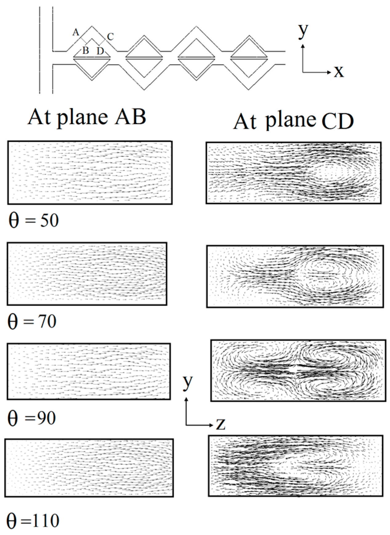
To determine why the mixing index shows its maximum at θ = 90°, the flow structures were plotted for different rhombic angles at Re = 50 (Figure 10). Velocity vectors were plotted on two y-z planes (AB and CD) just before and after the apex of the first rhombus, respectively. The flow patterns at plane AB are almost identical for all cases, and no transverse flow was observed throughout the cross-sectional area. At plane CD, the micromixer with θ = 50° creates a single elliptical vortex near the outer wall. A pair of counter-rotating vortices occur at θ = 70° and 110°. The centers of the vortices shifted to the outer wall at θ = 70°. Two pairs of counter-rotating vortices that occupy the entire cross-sectional area appear at θ = 90°. The strongest transverse motion produces the highest mixing index at θ = 90°, as shown in Figure 9. 
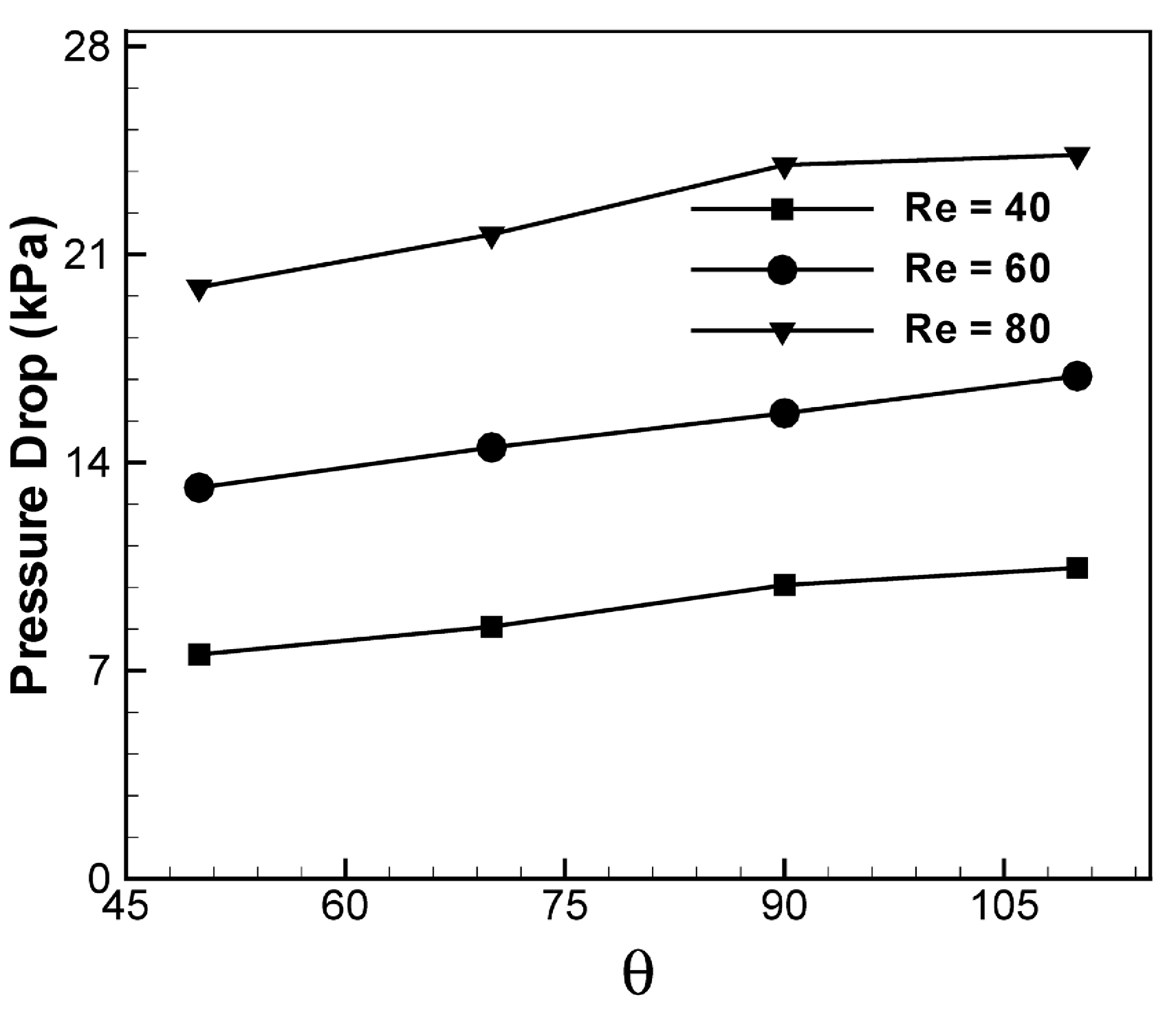
Figure 11 shows the effect of the rhombic angle on pressure drop in the three-split micromixer at Reynolds numbers of 40, 60, and 80. Pressure drops were calculated at the exit of the fourth rhombic unit for all cases. The pressure drop slowly increases at nearly a constant rate as the angle increases from 50°–110° for all tested Reynolds numbers. In the case of the three-split micromixer shown in Figure 1a, as the angle increases, the total flow path increases due to the increase in the pitch with fixed height, which contributes to the increase in pressure drop.
Figure 9. Effect of rhombic angle on mixing in the three-split micromixer for various Reynolds numbers.
Micromachines 05 00913 g009
Figure 10. Velocity vector plots on y-z planes at Re = 50 in the three-split micromixer for various rhombic angles.
Micromachines 05 00913 g010
Figure 11. Effect of rhombic angle on the pressure drop in the three-split micromixer for various Reynolds numbers.
Micromachines 05 00913 g011
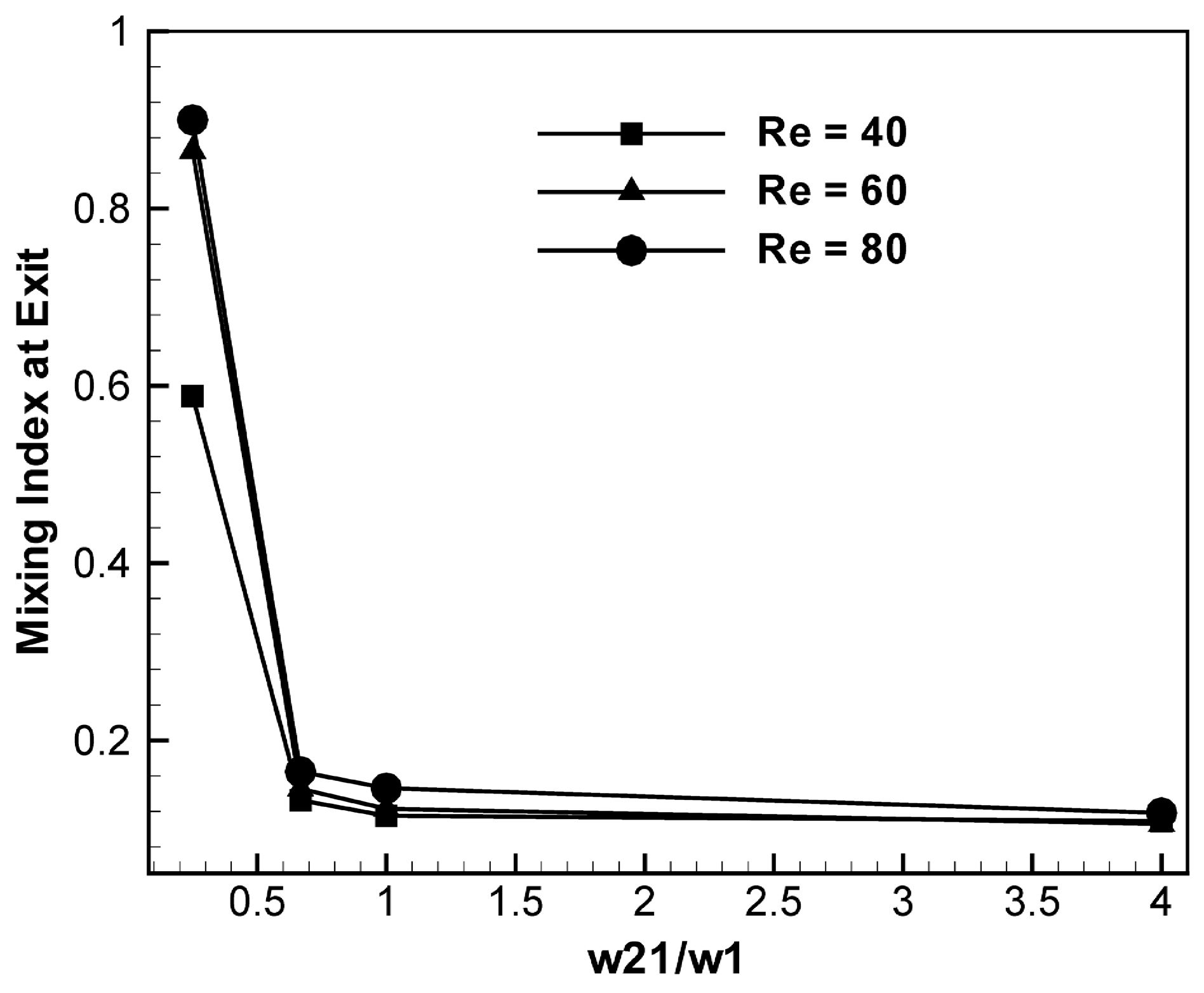
Figure 12 shows the effect of channel width on mixing at the exit of the fourth rhombic unit with Reynolds numbers of 40, 60, and 80. To understand the effect of sub-channel width on mixing performance and pressure drop, the value of the dimensionless parameter w21/w1 was varied from 0.25 to 4.0, as shown in Figure 13. The other geometric parameters (pitch, Pi, channel height, h, θ, and w = 0.3 mm) were kept constant. At the minimum value of w21/w1 (w21/w1 = 0.25), the mixing index reaches the maximum regardless of the Reynolds number, as shown in Figure 12. With an increase in w21/w1 from 0.25 to 1.0 mm, the mixing index decreases significantly. A further increase in w21/w1 causes only a slight decrease in the mixing index. A Reynolds number of 40 results in a much smaller mixing index than the other Reynolds numbers at w21/w1 = 0.25, but at the other values of w21, the mixing indices do not show much of a difference.
Figure 12. Effect of width of minor sub-channel 1 (w21) on mixing in the three-split micromixer for various Reynolds numbers.
Micromachines 05 00913 g012
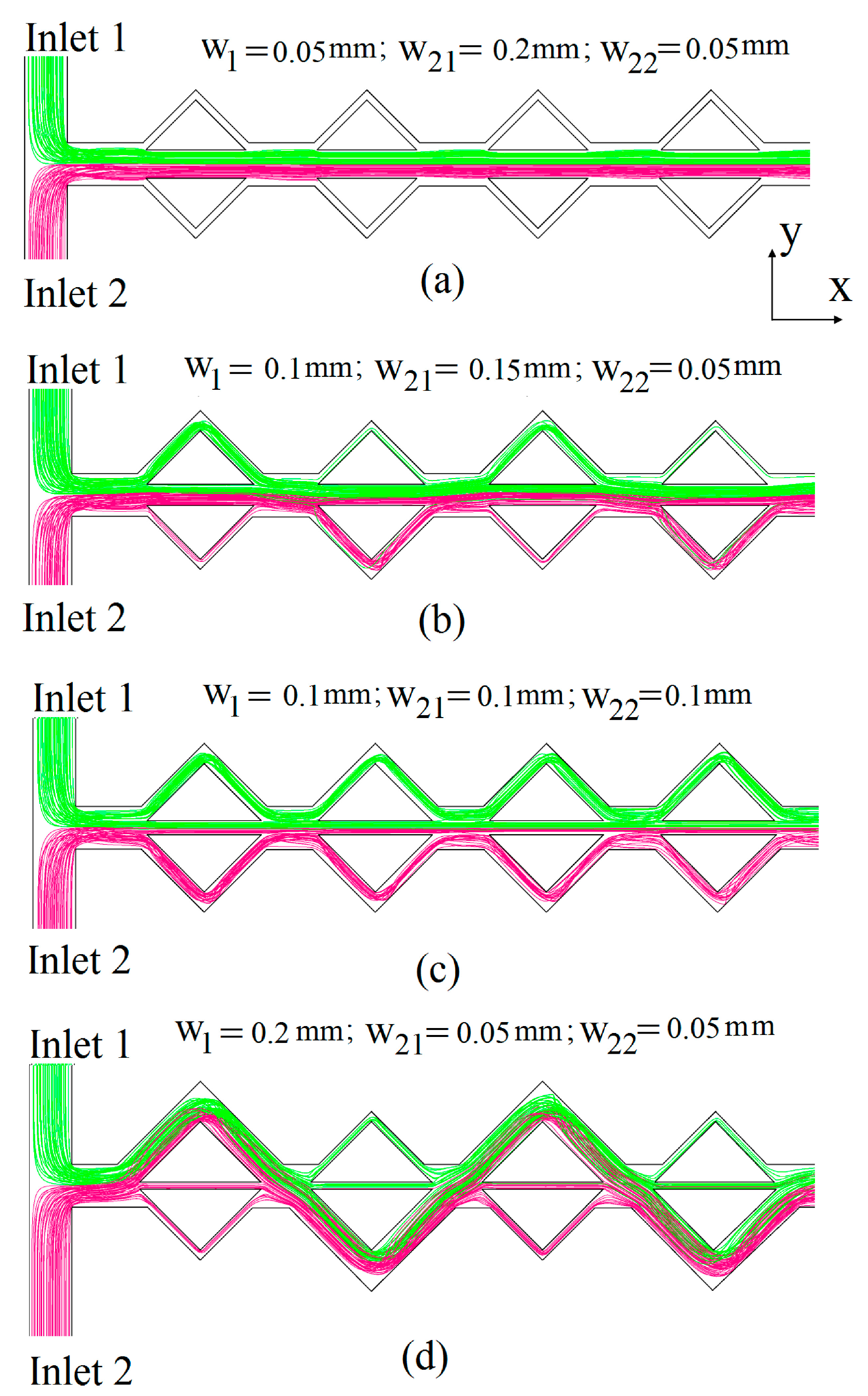
The mechanism of mixing between the fluids in the sub-channels, and the effect of sub-channel widths on mixing, can be seen in Figure 13, which shows projected streamlines of two different fluids entering from Inlet 1 and Inlet 2, respectively, at Re = 40. Figure 13a shows that the fluids entering from Inlet 1 and Inlet 2 mix at the T-joint, and most of the streamlines go to minor sub-channel 1 throughout the micromixer. Therefore, the unbalanced three-split rhombic micromixer with w21/w1 = 4.0 acts as a simple T-mixer, and mixing mainly occurs due to diffusion at the interface of the fluids. Figure 13b shows that for w21/w1 = 1.5, the streamlines from Inlet 1 enter the major sub-channel and minor sub-channels while most of the streamlines from Inlet 2 pass through minor sub-channel 1. Almost 95% of the total streamlines pass through minor sub-channel 1 with w21 = 0.15 mm. Figure 13c shows that for equal sub-channel widths (w21/w1 = 1.0), almost a half of the total number of streamlines pass through minor sub-channel 1. The remaining streamlines pass through the other sub-channels equally. Flow streamlines entering from each inlet stay in the sub-channel on their own side, and do not cross or alter each other. Figure 13d for the case with w21/w1 = 0.25 shows the best mixing performance (Figure 12), and indicates that the streamlines from Inlet 2 are divided into mainly two sub-streams. Most of the streamlines enter the major sub-channel and the remaining streamlines enter minor sub-channel 1, while the streamlines from Inlet 1 mostly go to the major sub-channel. After the first rhombic cell, the streamlines from the major sub-channel are divided into three sub-streams: the larger part goes to the next major sub-channel, and the remaining part enters the minor sub-channels equally. The streamlines from minor sub-channel 1 mostly go to the major sub-channel due to the inertia of the fluid. After the second rhombic unit, the streamlines mix at the combination zone and are divided into sub-streams in a similar fashion. This complicated SAR process enhances the mixing in the unbalanced three-split micromixer.
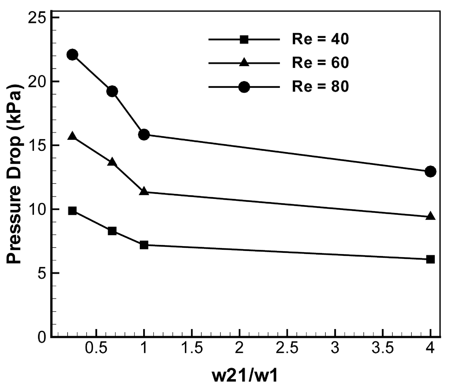
The effects of w21 on the pressure drop for Reynolds numbers of 40, 60, and 80 are shown in Figure 14. An equal axial distance of x = 5.3 mm was used to calculate the pressure drops. As w21/w1 increases, the pressure drop decreases at a nearly constant rate. This indicates that the wider central sub-channel causes the lower pressure drop, because it does not require a change in the flow direction of the incoming flow.
Figure 13. Projected streamlines starting from Inlet 1 and Inlet 2 at middle height of the channel and Re = 40 for the three-split micromixer for various minor sub-channel widths.
Micromachines 05 00913 g013
Figure 14. Effect of sub-channel width on the pressure drop for various Reynolds numbers.
Micromachines 05 00913 g014

5. Conclusions

The mixing performance and flow characteristics of the proposed micromixer with unbalanced three-split rhombic sub-channels were investigated by solving 3-D Navier-Stokes equations in combination with an advection-diffusion model for a Reynolds number range from 0.1–120. The mixing index and pressure drop were evaluated and compared with results from an unbalanced two-split rhombic micromixer. The micromixer with unbalanced three-split rhombic sub-channels exhibited better mixing performance than the two-split micromixer throughout the tested range of Reynolds numbers, except at Re = 120. At Reynolds numbers of 30, 40, 50, and 60, the mixing indices at the exit of the three-split micromixer are 1.49, 1.67, 1.56, and 1.44 times the corresponding mixing index of the two-split micromixer, respectively. The pressure drop in the three-split micromixer is larger than that in the two-split micromixer, but the relative difference is less than 16.8% throughout the Reynolds number range. Therefore, the proposed three-split micromixer shows good mixing performance in the Reynolds number range of 30–80 without an excessive increase in the pressure drop. A parametric study for the mixing performance and pressure drop in the three-split micromixer was also performed using two geometric parameters, the rhombic angle and sub-channel width ratio, in a Reynolds number range from 0.1–80. The mixing index at the exit has a maximum value at a rhombic angle of 90° with a fixed number of rhombic units of fixed height, except for the lowest Reynolds number of 0.1. At this Reynolds number, the mixing is only affected by the total path length of the channels. The pressure drop slowly increases at a nearly constant rate as the rhombic angle increases from 50°–110° for all tested Reynolds numbers. At a minimum value of w21/w1 (= 0.25) among the four test values, the mixing index reaches its maximum regardless of the Reynolds number. As w21/w1 increases, the pressure drop decreases at nearly a constant rate for all Reynolds numbers tested.

Acknowledgments

This research was supported by the National Research Foundation of Korea (NRF) Grant No. 20090083510 funded by government (MSIP) through Multi-phenomena CFD Engineering Research Center. The authors gratefully acknowledge this support.

Author Contributions

Shakhawat Hossain provides numerical simulation, analysis of the results and drafting the article to be submitted. Kwang-Yong Kim is a person who gives final approval of the version to be submitted.

Conflicts of Interest

The authors declare there are no conflicts of interest.

References

  1. Manz, A.; Graber, N.; Widmer, H.M. Miniaturized total chemical analysis systems: A novel concept for chemical sensing. Sens. Actuators B Chem. 1990, 1, 244–248. [Google Scholar]
  2. Verpoorte, E. Microfluidic chips for clinical and forensic analysis. Electrophoresis 2002, 23, 677–712. [Google Scholar] [CrossRef]
  3. Ehrlich, D.J.; Matsudaira, P. Microfluidic devices for DNA analysis. Trends Biotechnol. 1999, 17, 315–319. [Google Scholar] [CrossRef]
  4. Meldrum, D.R.; Holl, M.R. Microscale bioanalytical systems. Science 2002, 297, 1197–1198. [Google Scholar] [CrossRef]
  5. Reyes, D.R.; Iossifidis, D.; Auroux, P.A.; Manz, A. Micro total analysis systems. 1. Introduction, theory and technology. Anal. Chem. 2002, 74, 2623–2636. [Google Scholar]
  6. Hessel, V.; Lowe, H.; Schonfeld, F. Micromixers—A review on passive and active mixing principles. Chem. Eng. Sci. 2005, 60, 2479–2501. [Google Scholar] [CrossRef]
  7. Nguyen, N.-T.; Wu, Z. Micromixers—A review. J. Micromech. Microeng. 2005, 15, 1–16. [Google Scholar] [CrossRef]
  8. Oddy, M.H.; Santiago, J.G.; Mikkelsen, J.C. Electrokinetic instability micromixing. Anal. Chem. 2001, 73, 5822–5832. [Google Scholar] [CrossRef]
  9. Lu, L.H.; Ryu, K.S.; Liu, C. A magnetic microstirrer and array for microfluidic mixing. J. Microelectromech. Syst. 2002, 11, 462–469. [Google Scholar] [CrossRef]
  10. Liu, R.H.; Yang, J.; Pindera, M.Z.; Athavale, M.; Grodzinski, P. Bubble-induced acoustic micromixing. Lab Chip 2002, 2, 151–157. [Google Scholar] [CrossRef]
  11. Bessoth, F.G.; deMello, A.J.; Manz, A. Microstructure for efficient continuous flow mixing. Anal. Commun. 1999, 36, 213–215. [Google Scholar] [CrossRef]
  12. Gobby, D.; Angeli, P.; Gavriilidis, A. Mixing characteristics of T-type microfluidic mixers. J. Micromech. Microeng. 2001, 11, 126–132. [Google Scholar] [CrossRef]
  13. Vanka, S.P.; Luo, G.; Winkler, C.M. Numerical study of scalar mixing in curved channels at low Reynolds numbers. AIChE J. 2004, 50, 2359–2368. [Google Scholar] [CrossRef]
  14. Hossain, S.; Ansari, M.A.; Kim, K.Y. Evaluation of the mixing performance of three passive micromixers. Chem. Eng. J. 2009, 150, 492–501. [Google Scholar] [CrossRef]
  15. Ansari, M.A.; Kim, K.Y. Shape optimization of a micromixer with staggered herringbone groove. Chem. Eng. Sci. 2007, 62, 6687–6695. [Google Scholar] [CrossRef]
  16. Hossain, S.; Husain, A.; Kim, K.Y. Shape optimization of a micromixer with staggered herringbone grooves patterned on opposite walls. Chem. Eng. J. 2010, 162, 730–737. [Google Scholar]
  17. Hossain, S.; Ansari, M.A.; Husain, A.; Kim, K.Y. Analysis and optimization of a micromixer with a modified Tesla structure. Chem. Eng. J. 2010, 158, 305–314. [Google Scholar] [CrossRef]
  18. Lee, S.W.; Lee, S.S. Rotation effect in split and recombination micromixer. Sens. Actuators B Chem. 2008, 129, 364–371. [Google Scholar] [CrossRef]
  19. Viktorov, V.; Nimafar, M. A novel generation of 3D SAR-based passive micromixer: Efficient mixing and low pressure drop at a low Reynolds number. J. Micromech. Microeng. 2013, 23, 055023. [Google Scholar] [CrossRef]
  20. Nimafar, M.; Viktorov, V.; Martinelli, M. Experimental comparative mixing performance of passive micromixers with H-shaped sub-channels. Chem. Eng. Sci. 2012, 76, 37–44. [Google Scholar] [CrossRef]
  21. Nimafar, M.; Viktorov, V.; Martinelli, M. Experimental investigation of split and recombination micromixer in confront with basic T- and O-type micromixers. Int. J. Mech. Appl. 2012, 2, 61–69. [Google Scholar]
  22. Fang, W.F.; Yang, J.T. A novel microreactor with 3D rotating flow to boost fluid reaction and mixing of viscous fluids. Sens. Actuators B Chem. 2009, 140, 629–642. [Google Scholar] [CrossRef]
  23. Schönfeld, F.; Hessel, V.; Hofmann, C. An optimized split and recombine micro mixer with uniform chaotic mixing. Lab Chip 2004, 4, 65–69. [Google Scholar] [CrossRef]
  24. Ansari, M.A.; Kim, K.Y. Mixing performance of unbalanced split and recombine micomixers with circular and rhombic sub-channels. Chem. Eng. J. 2010, 162, 760–767. [Google Scholar] [CrossRef]
  25. Chung, C.K.; Shih, T.R. A rhombic micromixer with asymmetrical flow for enhancing mixing. J. Micromech. Microeng. 2007, 17, 2495–2504. [Google Scholar] [CrossRef]
  26. Chung, C.K.; Shih, T.R. Effect of geometry on fluid mixing of the rhombic micromixers. J. Microfluid. Nanofluid. 2008, 4, 419–425. [Google Scholar] [CrossRef]
  27. Ansari, M.A.; Kim, K.Y.; Anwar, K.; Kim, S.M. A novel passive micromixer based on unbalanced splits and collisions of fluid streams. J. Micromech. Microeng. 2010, 20, 055007. [Google Scholar] [CrossRef]
  28. CFX-12.1, Solver Theory; ANSYS Inc.: Canonsburg, PA, USA, 2006.
  29. Hardt, S.; Schonfeld, E. Laminar mixing in different inter-digital micromixers: II. Numerical simulations. AIChE J. 2003, 49, 578–584. [Google Scholar] [CrossRef]
  30. Van-Doormaal, J.P.; Raithby, G.D. Enhancement of the SIMPLE method for predicting incompressible fluid flows. Numer. Heat Transf. 1984, 7, 147–163. [Google Scholar]
  31. Ansari, M.A.; Kim, K.Y. A numerical study of mixing in a microchannel with circular mixing chambers. AIChE J. 2009, 55, 2217–2225. [Google Scholar] [CrossRef]
  32. Afzal, A.; Kim, K.Y. Passive split and recombination micromixer with convergent–divergent walls. Chem. Eng. J. 2012, 203, 182–192. [Google Scholar] [CrossRef]
  33. Wang, H.P.; Iovenitti, P.; Harvey, E.; Masood, S. Optimizing layout of obstacles for enhanced mixing in microchannels. Smart Mater. Struct. 2002, 11, 662–667. [Google Scholar]

