Flexible Helicoids, Atomic Force Microscopy (AFM) Cantilevers in High Mode Vibration, and Concave Notch Hinges in Precision Measurements and Research

Abstract
:
1. Introduction
2. Flexure and Stiffness of DNA Nano-Helicoidal Model


3. Scale Parameters of DNA Model Definition
3.1. Stretch Stiffness Relations


 .
.
N  | Calculation (1), (2), (3) | Experiment | |δ| (%) | ||||||||||
|---|---|---|---|---|---|---|---|---|---|---|---|---|---|
| νH | Lc (Å) | Var (Å2) | Lc (Å) | Var (Å2) | |||||||||
| a | b* | a | b* | a | b* | ae | b*e | a e | b*e | a | b* | ||
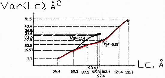
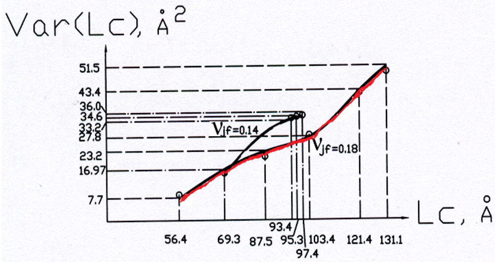
| 1 | −0.35 | −0.284 | 56.4 | 69.3 | 8.4 | 16.97 | 56.4 | 69.3 | 8.7 | 15.8 | 3.4 | 7.4 | |
| 2 | −0.228 | −0.210 | 86.1 | 93.4 | 22.5 | 33.2 | 86.1 | 93.4 | 21.2 | 34.0 | 6.1 | 2.3 | |
| 3 | −0.194 | −0.206 | 103.4 | 95.3 | 27.9 | 34.6 | 103.4 | 95.3 | 28.4 | 34.5 | 1.8 | 0.4 | |
| 4 | −0.167 | −0.205 | 121.4 | 95.8 | 43.4 | 35.05 | 121.4 | 95.8 | 42.4 | 35.0 | 2.4 | 0.1 | |
| 5 | −0.15 | −0.203 | 131.1 | 97.4 | 51.5 | 36.0 | 131.1 | 97.4 | 49.4 | 35.4 | 4.2 | 1.7 | |
3.2. Persistence Length Relations

 is an appropriately modified elastic modulus for the strip bending,
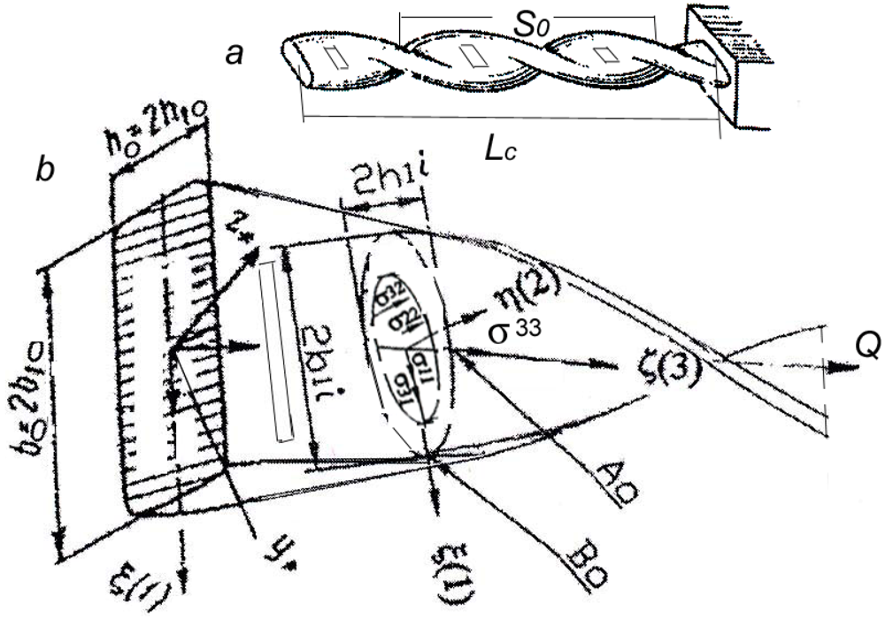
  nm4 is the moment of inertia for the hollow cross section (Figure 1(b)) of the model with pretwisted strip. We also assume that at different conditions (including temperature, type of solution) the value of nbp should be
  or 2 for the helix body with two surfaces: outer (o) and inner (i). This follows from the possible combination of thermomechanical statistical influence on the two surfaces as
  or from a necessary thermomechanical energy 2(kBT) at larger material deformation with larger |νp|. Our experience with the published experimental data [5,6,7] shows that the first value nbp = is more appropriate for a molecule with νp ≤ 0.2, νjf = 0.14 and the second value nbp = 2 for a molecule with νp = 0.5, νjf = 0.18 in standard solution with 70 mM Tris-Hl, pH 8.0 and 10 mM ascorbic acid. Equation (7) yields persistence length values at T = 293 K within 49–53 nm for both cases. In any case, the experimental value of jsp and Abp should preferably be measured or evaluated at the corresponding conditions because the persistence length depends on them [7,10] as well as on the molecular length [11]. A mean experimental value of the DNA persistence length in different cases and different solutions is equal to Abp = (30 + 80)/2 = 55 nm. The value of νjf is indeed a scale factor in Equation (2) which can and should be verified on an experimental and theoretical basis for certain representative point of the function in evaluation.
4. Calculation Results for DNA Model

5. Vibrating Transducers
5.1. The Helicoidal Pretwisted String
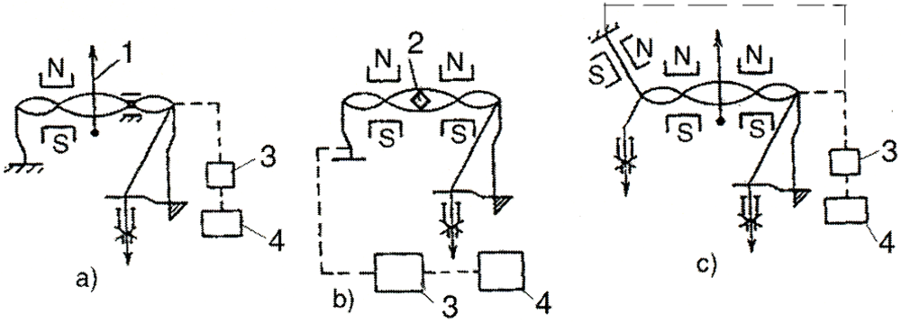
 , then for the helicoidal multivibrator we have the largest attainable natural frequency, which is equal to:

 and Be =
  ,
,  is a permissible yield stress for the string’s material,
  is its specific gravity,
  is a coefficient of form rigidity as for an elliptical cross section.
 which corresponds to the lowering of the string’s upper limit frequency by 22%. In deriving the relationship, we neglected the nonlinearity in the helicoidal multiplicator’s characteristics and a very small possible change of its density at the initial elastic-plastic twist. But the above shown lowering of the limit for attainable natural frequency in the helicoidal multivibrator is not important because with the increase of its pretension the sensitivity of the frequency transformation for the longitudinal displacement decreases. This shows that using the range of frequencies, which are close to the maximum attainable one for string, is pointless in the case of the helicoidal multivibrator.
 5.2. AFM Cantilevers

 at calibration the frequency fc0 of a rectangular cantilever with length Lr and then use the resulting value h =
  for calculation of the fundamental frequency of cantilevers with the other shapes. In this case we don’t need to check the real values of thickness, Young’s modulus, and specific density of the cantilever separately, especially at a high Q-factor. Equation (9) can be used for cantilevers coated [1] by films of gold, platinum, and even immobilized DNA molecule short ligands as well. Our helicoidal DNA model parameters [4] are especially effective in the latter case.
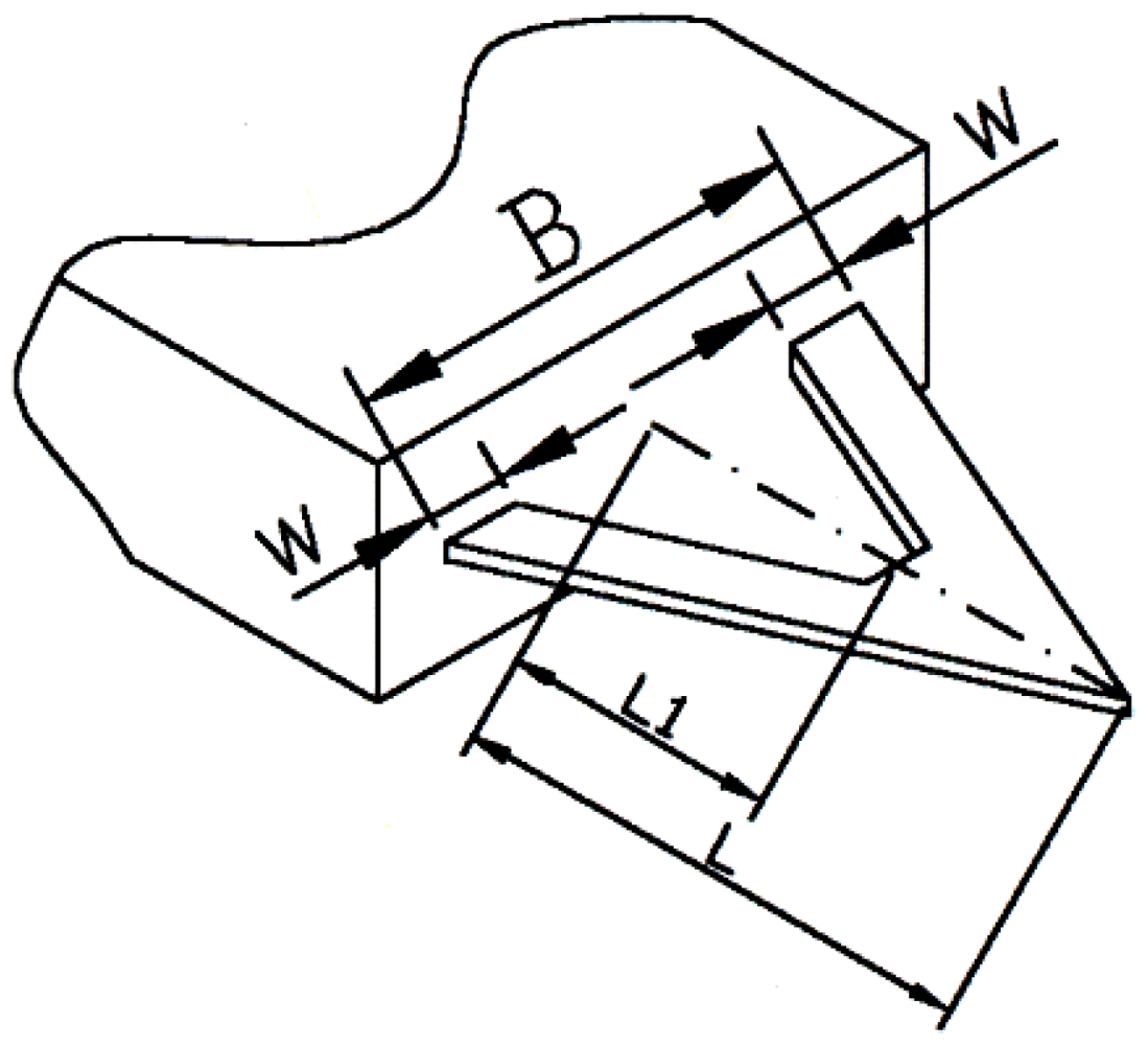
6. Concave Flexure Hinges and Their Instantaneous Center of Rotation


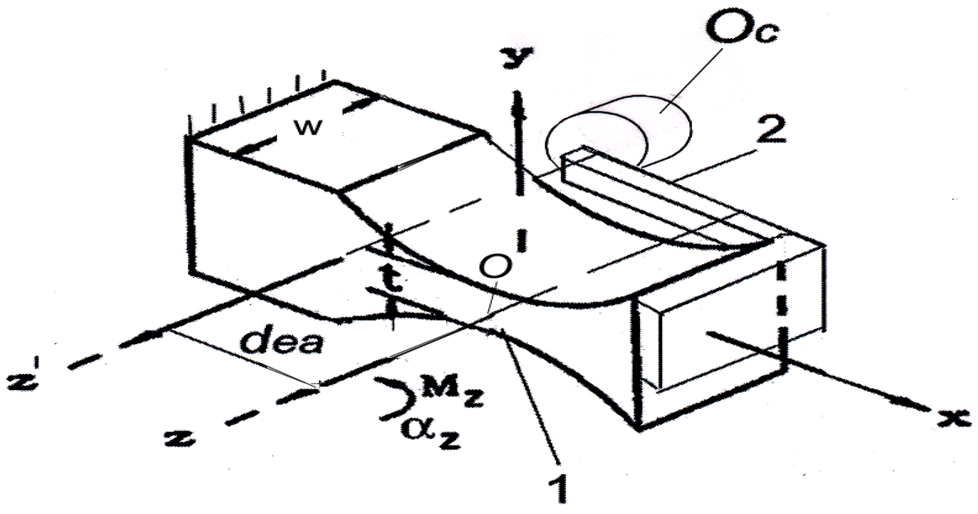
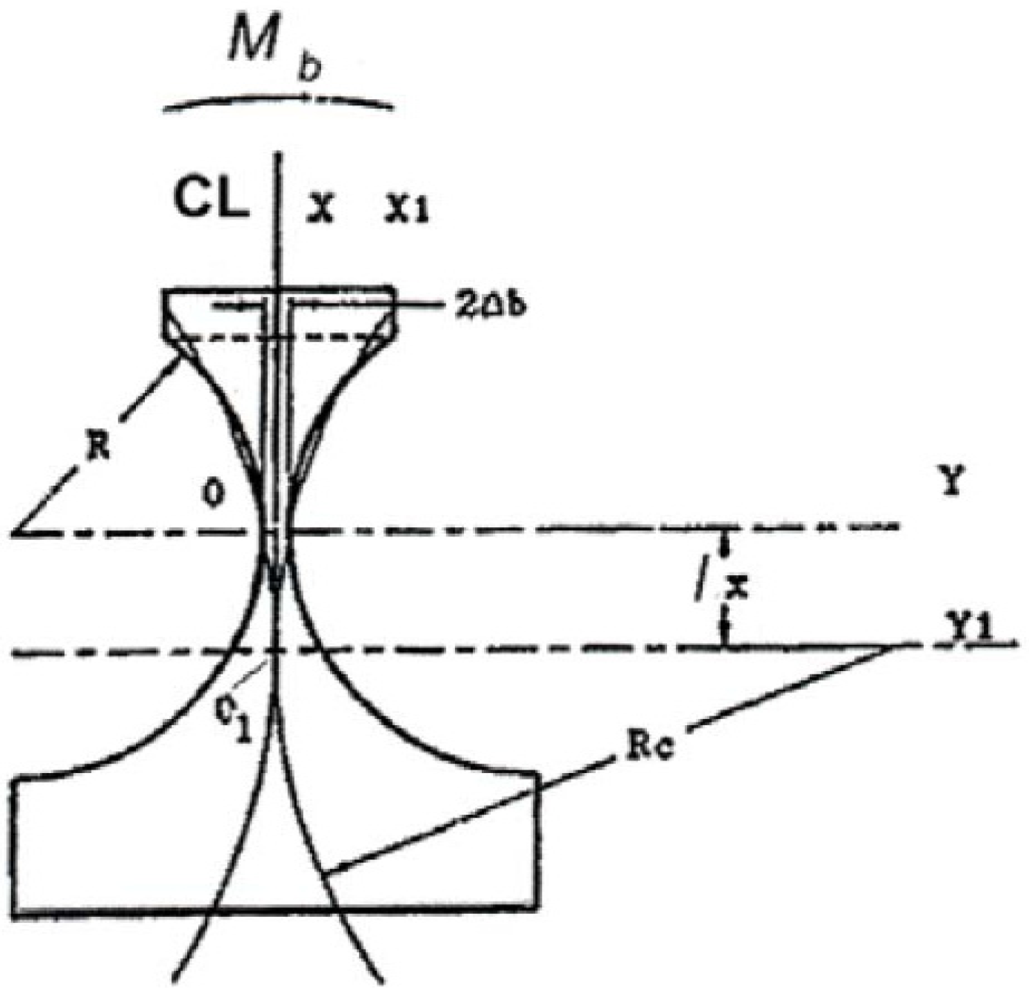
 dea/6 = 0.00017dea and YICR =
  dea/2 = 0.005dea shift of ICR coordinates from their initial (−dea, 0) position, which corresponds to the roll without sliding for circle of rolling on the pole tangent [1]. This may be considered in many cases as a practically negligible shift.
 7. Conclusions
Acknowledgements
References
- Tseytlin, Y.M. Structural Synthesis in Precision Elasticity; Springer: New York, NY, USA, 2006; p. 397. [Google Scholar]
- Perry, J. Twisted strips. Proc. Phys. Soc. Lond. 1890, XLIV, 343–349. [Google Scholar]
- Tseytlin, Y.M. Computation of spring-loaded instrument mechanism. Meas. Techniq. 1965, 8, 223–226. [Google Scholar] [CrossRef]
- Tseytlin, Y.M. An effective model of DNA like helicoid structure: With length fluctuation nonlinearity. AIP Adv. 2011, 1, 012116:1–012116:6. [Google Scholar]
- Mathew-Fenn, R.S.; Das, R.; Harbury, P.A.B. Remeasuring the double helix. Science 2008, 322, 446–449. [Google Scholar]
- Mathew-Fenn, R.S.; Das, R.; Silverman, J.A.; Walker, P.A.; Harbury, P.A.B. A molecular ruler for measuring quantitive distance distribution. PLoS One 2008, 3, e3229. [Google Scholar]
- Mathew-Fenn, R.S.; Das, R.; Fenn, T.D.; Schneiders, M.; Harbury, P.A.B. Response to comment on “Remeasuring the double helix”. Science 2009. [Google Scholar] [CrossRef]
- Bustamante, C.; Bryant, Z.; Smith, S.B. Ten years of tension: Single-molecule DNA mechanics. Nature 2003, 421, 423–427. [Google Scholar]
- Bodal, D. Mechanics of the Cell; Cambridge University Press: London, UK, 2002; p. 406. [Google Scholar]
- Dobrynin, A.V. Effect of counterion condensation on rigidity of semiflexible polyelectrolytes. Macromolecules 2006, 39, 9519–9527. [Google Scholar] [CrossRef]
- Eslami-Mossallam, B.; Ejtehadi, M.R. Contribution of nonlocal interactions to DNA elasticity. J. Chem. Phys. 2011, 134, 125106:1–125106:9. [Google Scholar]
- Tseytlin, Y.M. Atomic force microscope cantilever spring constant evaluation for higher mode oscillations: A kinetostatic method. Rev. Sci. Instrum. 2008, 79, 025102:1–025102:7. [Google Scholar]
- Tseytlin, Y.M. High resonant mass sensor evaluation: An effective method. Rev. Sci. Instrum. 2005, 76, 115101:1–115101:6. [Google Scholar]
- Tseytlin, Y.M. Kinetostatic model of spring constant ratios for an AFM cantilever with end extended mass. Ultramicroscopy 2010, 110, 126–129. [Google Scholar] [CrossRef]
- Tseytlin, Y.M. Nanostep and film-coating thickness traceability. In Proceedings of the 53 IIS, Tulsa, OK, USA, 30 April–3 May 2007; 470, pp. Papertp007iis006:1–Papertp007iis006:6.
- Tseytlin, Y.M. Tractable model for concave flexure hinges. Rev. Sci. Instrum. 2011, 82, 015106:1–015106:4. [Google Scholar]
- Tseytlin, Y. Note: Rotational compliance and instantaneous center of rotation in segmented and V-shaped notch hinges. Rev. Sci. Instrum. 2012, 83, 026102:1–026102:3. [Google Scholar]
- Linβ, S.; Erbe, T.; Theska, R.; Zentner, L. The influence of asymmetric flexure hinges on the axis of rotation. In Proceedings of the 56th International Scientific Colloquium, Ilmenau University of Technology, Ilmenau, Germany, 12–16 September 2011; p. 10.
© 2012 by the authors; licensee MDPI, Basel, Switzerland. This article is an open-access article distributed under the terms and conditions of the Creative Commons Attribution license (http://creativecommons.org/licenses/by/3.0/).
Share and Cite
Tseytlin, Y. Flexible Helicoids, Atomic Force Microscopy (AFM) Cantilevers in High Mode Vibration, and Concave Notch Hinges in Precision Measurements and Research. Micromachines 2012, 3, 480-491. https://doi.org/10.3390/mi3020480
Tseytlin Y. Flexible Helicoids, Atomic Force Microscopy (AFM) Cantilevers in High Mode Vibration, and Concave Notch Hinges in Precision Measurements and Research. Micromachines. 2012; 3(2):480-491. https://doi.org/10.3390/mi3020480
Chicago/Turabian StyleTseytlin, Yakov. 2012. "Flexible Helicoids, Atomic Force Microscopy (AFM) Cantilevers in High Mode Vibration, and Concave Notch Hinges in Precision Measurements and Research" Micromachines 3, no. 2: 480-491. https://doi.org/10.3390/mi3020480