Abstract
We present a switchable thermal interface based on an array of discrete liquid droplets initially confined on hydrophilic islands on a substrate. The droplets undergo reversible morphological transition into a continuous liquid film when they are mechanically compressed by an opposing substrate to create low-thermal resistance heat conduction path. We investigate a criterion for reversible switching in terms of hydrophilic pattern size and liquid volume. The dependence of the liquid morphology and rupture distance on the diameter and areal fraction of hydrophilic islands, liquid volumes, as well as loading pressure is also characterized both theoretically and experimentally. The thermal resistance in the on-state is experimentally characterized for ionic liquids, which are promising for practical applications due to their negligible vapor pressure. A life testing setup is constructed to evaluate the reliability of the interface under continued switching conditions at relatively high switching frequencies.
1. Introduction
Switchable thermal interfaces enable controlled modulation of thermal conductance between devices of interest and their heat sinks/sources. They are key components of micro-devices and systems that require reconfigurable heat transfer paths for precise low-power thermal control and management. Potential applications [1,2,3,4] include micro-bolometers with locally adjustable dynamic ranges, pulsed thermoelectric cooling, solid-state electrocaloric refrigerators that require rapid thermal cycling of the working medium, pyroelectric waste heat harvesting, and satellite thermal management.
It is well-established that thermal transport across solid-solid contacts is often limited by surface asperities that reduce actual contact areas. Previous experimental studies showed, however, that significant loading pressure (of the order of 1 MPa) is necessary to achieve small thermal contact resistance (<10−4 m2·K·W) even for micromachined silicon surfaces with nanometer scale roughness [1]. This may be attributed to trapped gas layers that strongly impede heat conduction. Dense arrays of vertically aligned carbon nanotubes [5] or nanofibers [6] have received a lot of attention for potential heat transfer applications. Relatively large loading pressure was, however, often necessary to achieve small thermal resistance because only a small fraction of tubes actually make contact with the opposing surface. Furthermore, under intimate contacts, strong adhesion between carbon nanotubes and the opposing surface [7] and resulting delamination failures make them ill-suited as switchable thermal interfaces.
A previous study demonstrated a related thermal switch that consists of an array of discrete mercury droplets [2]. Since the thermal conductivity of mercury is relatively high, the thermal resistance across each droplet can be very low (~4 × 10⁻⁶ m2·K·W). Mercury, however, poses health and environmental hazards. Some alternative room-temperature liquid metals can circumvent this issue, but they oxidize rapidly in the ambient air, making their practical use difficult.
A recent study demonstrated the potential for an alternative liquid-mediated thermal interface, which can provide thermal contact resistance comparable to that of direct solid-solid contacts at loading pressure several orders of magnitude smaller [8]. The key idea was to exploit the predominance of surface tension over gravity and other bulk forces at microscales to reversibly change the morphology of parallel columns of a dielectric liquid confined in microchannels. In its off-state, the two surfaces defining the interface are separated from each other by an air or vacuum gap. The liquid is confined in an array of discrete microchannels separated from each other by hydrophobic regions. The two surfaces are then brought into contact to compress and deform the liquid columns until a continuous liquid layer is formed. To switch off the interface, the two surfaces are pulled away from each other. The continuous liquid layer is then first transformed into an array of liquid bridges spanning the gap, which then rupture to break thermal contact between the two surfaces.
The channel-based liquid thermal interface has the advantages that it can be easily manufactured using standard microfabrication techniques and that each channel can readily be filled with a precise amount of liquid to control the final gap distance.
The main drawback of this design, however, has to do with its requirement for a long mechanical stroke. The distance required for liquid-bridges to rupture is of the order of the length of microchannels or typically ~1 mm. This can be problematic in applications that require micro-actuators of limited actuation ranges or rapid thermal cycling.
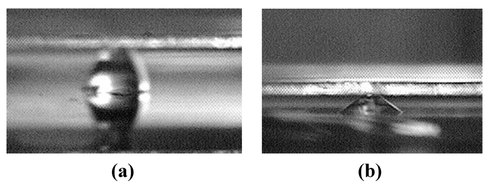
The present work reports our theoretical and experimental work on an alternative design that replaces microchannels with an array of discrete chemically-patterned hydrophilic islands to reduce or otherwise control the liquid-bridge rupture distance. As an illustration, Figure 1 shows a difference in rupture distance between two designs. For one liquid volume considered, the rupture distance of the interface containing circular islands is below 300 µm [Figure 1(a)], whereas that of the interface containing parallel microchannels is over 700 µm [Figure 1(b)].

Figure 1.
Comparison between the rupture distances of liquid bridges defined by (a) microchannels and (b) discrete hydrophilic patterns.
Figure 1.
Comparison between the rupture distances of liquid bridges defined by (a) microchannels and (b) discrete hydrophilic patterns.
2. Interface Design: Reversibility
One key design consideration for the switchable thermal interfaces is their reversibility. That is, a continuous liquid film formed by deforming and merging an array of discrete liquid droplets must be able to return to the original state of discrete droplets when the two surfaces are separated from each other.
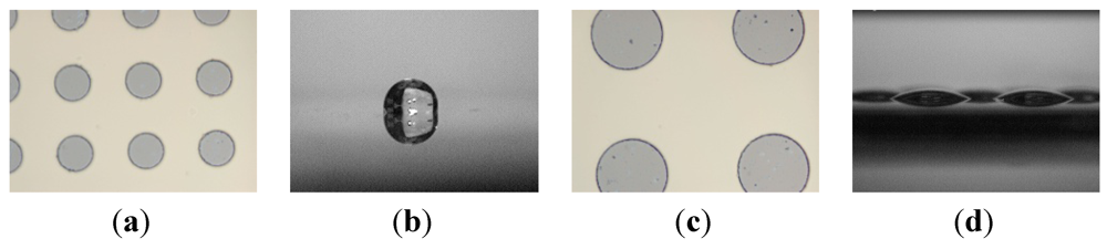
We consider an array of circular hydrophilic patches on an otherwise hydrophobic surface as our model system. The two main design parameters are (1) pattern size d as characterized by their diameter and (2) the pattern areal fraction f, which is defined as the fraction of the surface area occupied by hydrophilic islands. When d or f is too small, a continuous liquid film formed in the switch-on state may transform into a single large liquid drop instead of an array of multiple discrete droplets as illustrated in Figure 2.

Figure 2.
Comparison between large and small patterns. Liquid on the substrate with smaller hydrophilic patterns (a) will transform into a single droplet after rupture (b) but on the substrate with larger hydrophilic patterns (c) will form discrete droplets (d).
Figure 2.
Comparison between large and small patterns. Liquid on the substrate with smaller hydrophilic patterns (a) will transform into a single droplet after rupture (b) but on the substrate with larger hydrophilic patterns (c) will form discrete droplets (d).
To establish quantitative reversibility criteria, we compare the interface energy of the single-droplet state Es and that of the discrete multi-droplet state Em. Assuming that the effect of the gravity is negligible, we can approximate liquid droplets as truncated spheres. The interfacial energy can then be written as
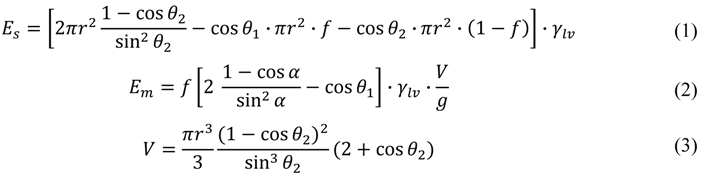
Here r is the radius of the wetting area of the single droplet, which is determined by the total volume (Equation (3)), is the apparent contact angle of a discrete droplet on each hydrophilic pattern, g is the desired minimum gap (that is, the target minimum thickness of the continuous liquid layer), and V is the total liquid volume.
Figure 3 shows the calculated interfacial energy for the two states at f = 0.2, V = 0.7 μL and g = 20 μm. We consider a case where the contact angle on the hydrophilic pattern is θ1 = 24.4° (experimentally measured for silicon after plasma etching of a hydrophobic coating) and that on the hydrophobic region (e.g., Teflon® coating) θ2 is 120°. The liquid-vapor surface tension γlv = 73 mN/m is assumed to be comparable to that of water.
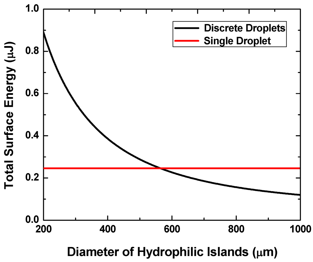
Figure 3.
Interface energies of the single-droplet state and the multi-droplet states versus pattern size.
Figure 3.
Interface energies of the single-droplet state and the multi-droplet states versus pattern size.

When the pattern size is below approximately 560 μm, the discrete multi-droplet state has higher energy and is hence less energetically favorable than the single-drop state. That is, a continuous liquid layer will more likely transform into a single large liquid drop when the two surfaces are separated from each other instead of forming multiple discrete droplets. The pattern size needs to exceed this value to achieve the reversibility.
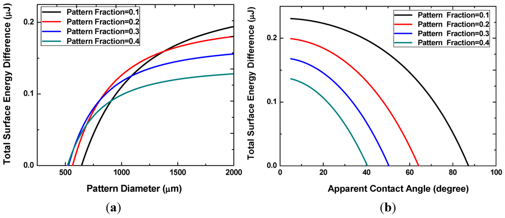
Figure 4(a) shows the difference in the interfacial energy of the two states for different values of the pattern areal fraction f. The x-intercepts, ranging from approximately 500 to 700 μm, correspond to the minimum pattern size necessary for the discrete multi-drop state to be energetically more favorable. This minimum pattern size decreases with increasing f. In other words, smaller patterns can achieve reversibility at higher pattern fractions because the neighboring hydrophilic patterns are located closer to each other. When the pattern size becomes very large, the interfacial energy difference decreases with increasing pattern density. Liquid droplets on these large patterns are more prone to merge and form a single large drop. As shown in Figure 4(b), smaller apparent angles are necessary to prevent the coalescence of neighboring liquid drops at higher pattern fractions.

Figure 4.
Interface energy difference with different pattern sizes and densities (a), or with different apparent angles of the discrete droplets (b).
Figure 4.
Interface energy difference with different pattern sizes and densities (a), or with different apparent angles of the discrete droplets (b).
3. Interface Design: Rupture Distance
We use the surface energy minimization algorithm to predict the equilibrium configuration of a liquid bridge as a function of spacing between the two bounding solid surfaces. The configuration (or shape) of the liquid bridge that minimizes the total interfacial energy is found using an iterative algorithm implemented using Surface Evolver [9,10]. The maximum gap below which the liquid bridge remains the most stable configuration is set as the rupture distance.
The rupture distance is also experimentally measured using a dual camera setup to observe the side and top view of a liquid bridge formed between a transparent glass top substrate and a silicon substrate. The side view images are used to quantify the droplet or bridge profiles and check the parallelism of the two substrates. The top view is used to determine the liquid film thickness from the known liquid volume and the observed area of the liquid layer. The top substrate is mounted on a precision z-stage to control the gap between the substrates. The resolution of the imaging system is approximately 5 μm. Figure 5 shows representative optical images obtained while raising the top substrate.

Figure 5.
Cross sectional images illustrating morphological transition at the rupture point.
Figure 5.
Cross sectional images illustrating morphological transition at the rupture point.
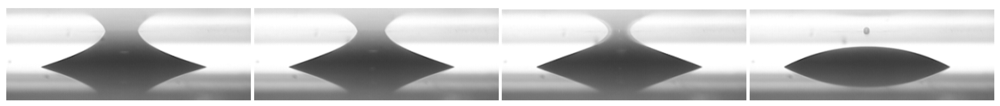
Figure 6 shows the predicted and measured rupture distances for samples with three different hydrophilic pattern sizes (0.5 mm, 1 mm and 1.5 mm) and for five different values of the pattern areal fraction, f. The total volume is fixed at 0.7 μL with the target minimum gap g of 20 μm. The rupture distance decreases with increasing f because, for a given total liquid volume, the height of discrete liquid droplets on each hydrophilic pattern is smaller at higher pattern areal fractions. For a given areal fraction, the rupture distance also scales roughly with the pattern size. The prediction agrees well with the measured rupture distances for all the cases examined here.
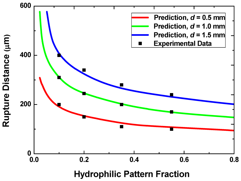
Figure 6.
Rupture distances with different pattern sizes and areal fractions.
Figure 6.
Rupture distances with different pattern sizes and areal fractions.

When the design goal is to achieve a small rupture distance, one would prefer smaller pattern sizes and higher areal fractions. This requirement, however, conflicts with the requirement for achieving the reversibility discussed in the preceding section. One may therefore select the smallest acceptable pattern size that ensures reversible switching for a given areal fraction to reduce the rupture distance.
4. Capillary Forces
Another important mechanical characteristic of liquid-based interfaces is the force-gap relation. We predict this relation using the virtual work model in conjunction with the surface energy minimization algorithm. The capillary force is computed as the first derivative of the interfacial energy of the equilibrium bridge configuration: F = −dE/dg. The force-gap relation is also experimentally characterized by placing the bottom substrate on a precision balance to measure the force while reducing (or increasing) the gap between the two substrates using the precision z-stage.
Figure 7 shows the measured and predicted loading pressure as a function of gap for substrates with the fixed hydrophilic pattern diameter of 1 mm. In transitioning from the off- to on-state, multiple liquid bridges are first formed between the two substrates. For the multiple-bridge states, the different curves in the figure correspond to different values of the pattern areal fraction, f. These curves then merge into one universal curve once a continuous thin film is formed. The effect of contact angle hysteresis is small. As the travel direction is reversed and the gap distance is increased, the attractive component of the surface tension force eventually exceeds the repulsive force, and the net force becomes positive. After the multi-bridge state is reached again, the repulsive Laplace pressure decreases as the bottom apparent contact angle changes and the surface tension force becomes more dominant.
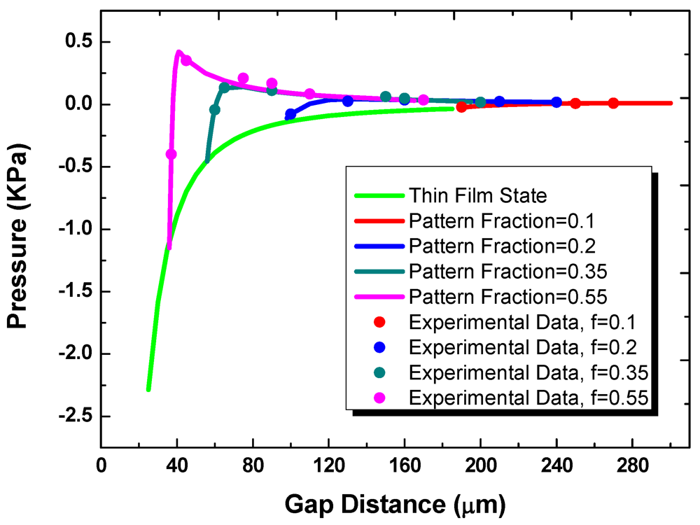
Figure 7.
The pressure as a function of gap distance at thin film state and multi-bridge state.
Figure 7.
The pressure as a function of gap distance at thin film state and multi-bridge state.

5. Switching Work
The total work required for one switching operation (on-to-off or off-to-on) may be calculated as the sum of the work necessary to push the substrates to achieve a desired gap distance (work of actuation) and the work necessary to pull the substrates and cause rupture (work of separation). Table 1 shows the values obtained by integrating the loading force as a function of gap distance for substrates with the fixed pattern diameter of 1 mm. They are compared with the difference between the total surface energies between the discrete multi-droplet state and the thin-film state.

Table 1.
The total operation work with different pattern areal fractions.
| Pattern Fraction | Energy Difference (μJ) | Total Work (μJ) | Work of Actuation (μJ) | Work of Separation (μJ) |
|---|---|---|---|---|
| 0.1 | 2.1 | 2.2 | 2.2 | 0.02 |
| 0.2 | 1.8 | 1.9 | 2.0 | 0.13 |
| 0.35 | 1.2 | 1.4 | 1.7 | 0.28 |
| 0.55 | 0.5 | 0.88 | 1.3 | 0.47 |
6. Thermal Resistance Characterization
Figure 8 schematically shows the experimental setup we use for thermal resistance measurements. We use a serpentine metal strip microfabricated on a glass slide (top substrate) as a heater and electrical resistance thermometer to characterize the thermal resistance of liquid layers (on-state interface thermal resistance). We apply a current pulse to the heater and monitor resulting changes in its electrical resistance and hence temperature as a function of time. The temporal temperature profile is then analyzed using finite element simulations to extract the thermal resistance [8].
We use de-ionized water for the experiments discussed in the preceding sections for the capillary force and rupture distance because it allows the surfaces to be readily cleaned and reused. For practical applications, non-volatile liquids, such as hydrophobic ionic liquids [11] may be more suited. We picked two commercial available ionic liquids, 1-butyl-3-methylimidazolium tetrafluoroborate, [BMIM][BF4] and 1-butyl-3-methylimidazolium hexafluorophosphate, [BMIM][PF6], for further test.

Figure 8.
Schematic of the measurement setup for thermal resistance (transient hot disk technique).
Figure 8.
Schematic of the measurement setup for thermal resistance (transient hot disk technique).
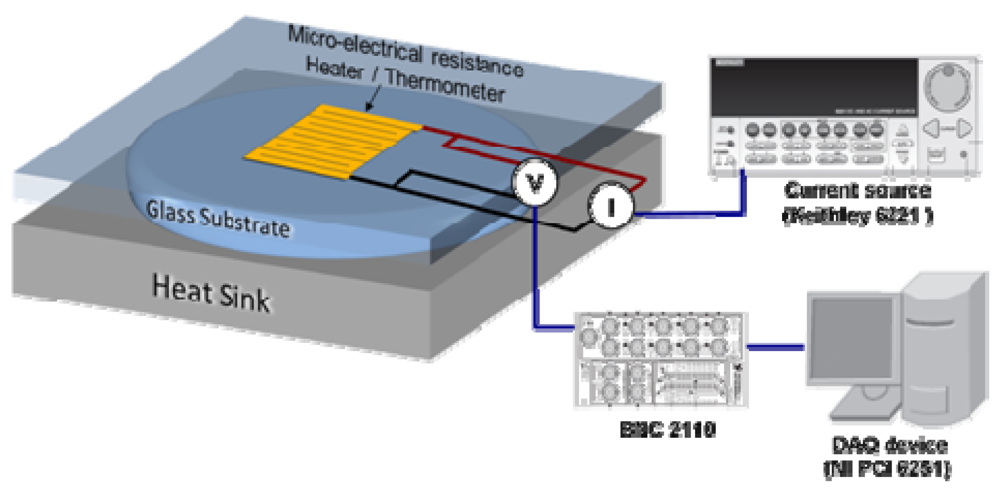
Figure 9 shows the experimentally measured temporal temperature profiles and the corresponding FEM simulation results. The thickness of the [BMIM][BF4] layer is 12 μm and the thickness of the [BMIM][PF6] layer is 10 μm. The initial parts of the temporal profiles (not shown) are governed primarily by heat conduction through the glass slide and not sensitive to the thermal resistance of the interface.
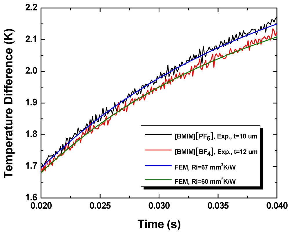
Figure 9.
Temporal temperature profiles obtained during experiments and the best fits obtained using finite element simulations.
Figure 9.
Temporal temperature profiles obtained during experiments and the best fits obtained using finite element simulations.

From the measured thermal resistance and liquid layer thickness, we determine the thermal conductivity of [BMIM][BF4] to be 0.19 ± 0.01 W/mK and that of [BMIM][PF6] to be 0.15 ± 0.01 W/mK. These compare well with the literature values of bulk samples, 0.186 W/mK and 0.145 W/mK, respectively. This suggests that the thermal boundary resistance at liquid-solid interfaces, which arise from finite mismatch in the acoustic (phonon) properties of the two substances, is negligible compared with the bulk thermal resistance of the liquid layers.
7. Life Testing
To obtain preliminary evaluation of the reliability of the present switchable interfaces, we constructed an experimental setup shown in Figure 10. A spring-supported frame bonded with a magnetic foil is actuated by rotating a disk embedded with multiple permanent magnets. The frame is separated from the disk by a substrate containing a switchable liquid-based interface. The disk was rotated using a DC motor to actuate the plate up and down and make mechanical contacts with the interface at a controlled frequency. The liquid interfaces were shown to operate reliably at frequencies as high as 20 Hz for at least 1,000 h. For some ionic liquids, such as [BMIM][PF6] that contain fluorine atoms [12], the total liquid volume decreases with time due to formation of volatile species upon exposure to the ambient air. This may lead to interface failure when the liquid droplets are depinned from the pattern boundaries. Such problems may be avoided in other ionic liquids, including 1-ethyl-3-methylimidazolium dicyanamide that we tested.
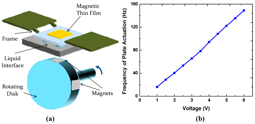
Figure 10.
(a) Schematic of the life testing setup; (b) Plate actuation frequency as a function of voltage applied to the DC motor.
Figure 10.
(a) Schematic of the life testing setup; (b) Plate actuation frequency as a function of voltage applied to the DC motor.

8. Summary
The present work establishes a concept for switchable thermal interfaces based on an array of discrete liquid droplets initially confined on hydrophilic islands on a hydrophobic substrate. The droplets undergo reversible morphological transition into a continuous liquid film when they are mechanically compressed by an opposing substrate to create low-thermal resistance heat conduction path. We investigate a criterion for reversible switching in terms of hydrophilic pattern size and liquid volume. The dependence of the liquid morphology and rupture distance on the diameter and areal fraction of hydrophilic islands, liquid volumes, as well as loading pressure is also characterized both theoretically and experimentally. The thermal resistance in the on-state is experimentally characterized for ionic liquids, which are promising for practical applications due to their negligible vapor pressure. A life testing setup is constructed to evaluate the reliability of the interface under continued switching conditions at relatively high switching frequencies.
Acknowledgment
The present article is based on work sponsored in part by the United States ARPA-E under Award Number (DE-AR0000120) and in part by the United States National Science Foundation under Award Number (CBET-1048726). Neither the United States Government nor any agency thereof, nor any of their employees, makes any warranty, express or implied, or assumes any legal liability or responsibility for the accurate, completeness, or usefulness of any information, apparatus, product or process disclosed, or represents that its use would not infringe privately owned rights. Reference herein to any specific commercial products, process, or service by trade name, trademark, manufacturer, or otherwise does not necessarily constitute or imply its endorsement, recommendation, or favoring by the United States Government or any agency thereof. The views and opinions of authors expressed herein do not necessarily state or reflect those of the United States Government or any agency thereof.
References
- Song, W.; Sutton, M.S.; Talghader, J.J. Thermal contact conductance of actuated interfaces. Appl. Phys. Lett. 2002, 81, 1216–1218. [Google Scholar] [CrossRef]
- Cho, J.; Richards, C.; Bahr, D.; Jiao, J.; Richards, R. Evaluation of contacts for a MEMS thermal switch. J. Micromech. Microeng. 2008, 18. [Google Scholar]
- Ghoshal, U.; Ghoshal, S.; McDowell, C.; Shi, L.; Cordes, S.; Farinelli, M. Enhanced thermoelectric cooling at cold junction interfaces. Appl. Phys. Lett. 2002, 80, 3006–3008. [Google Scholar]
- Biter, W.; Oh, S.; Hess, S. Electrostatic Switched Radiator for Space Based Thermal Control. In Proceedings of Space Technology and Applications International Forum (STAIF-2002), Albuquerque, NM, USA, 3–6 February 2002; pp. 73–80.
- Xu, J.; Fisher, T.S. Enhancement of thermal interface materials with carbon nanotube arrays. Int. J. Heat Mass Tran. 2006, 49, 1658–1666. [Google Scholar] [CrossRef]
- Ngo, Q.; Cruden, B.A.; Cassell, A.M.; Sims, G.; Meyyappan, M.; Li, J.; Yang, C.Y. Thermal interface properties of Cu-filled vertically aligned carbon nanofiber arrays. Nano Lett. 2004, 4, 2403–2407. [Google Scholar] [CrossRef]
- Zaho, Y.; Tong, T.; Delzeit, L.; Kashani, A.; Meyyapan, M.; Majumdar, A. Interfacial energy and strength of multiwalled-carbon-nanotube-based dry adhesive. J. Vac. Sci. Technol. B 2006, 24, 331:1–331:5. [Google Scholar]
- Cha, G.; Ju, Y.S. Reversible thermal interfaces based on microscale dielectric liquid layers. Appl. Phys. Lett. 2009, 94, 211904:1–211904:3. [Google Scholar]
- de Souza, E.J.; Brinkmann, M.; Mohrdieck, C.; Arzt, E. Enhancement of capillary forces by multiple liquid bridges. Langmuir 2008, 24, 8813–8820. [Google Scholar]
- de Souza, E.J.; Brinkmann, M.; Mohrdieck, C.; Crosby, A.; Arzt, E. Capillary forces between chemically different substrates. Langmuir 2008, 24, 10161–10168. [Google Scholar]
- Valkenburg, M.E.V.; Vaughn, R.L.; Williams, M.; Wilkes, J.S. Thermochemistry of ionic liquid heat-transfer fluids. Thermochim. Acta 2005, 425, 181–188. [Google Scholar] [CrossRef]
- Swatloski, R.P.; Holbrey, J.D.; Rogers, R.D. Ionic liquids are not always green: Hydrolysis of 1-butyl-3-methylimidazolium hexafluorophosphate. Green Chem. 2003, 5, 361–363. [Google Scholar] [CrossRef]
© 2012 by the authors; licensee MDPI, Basel, Switzerland. This article is an open-access article distributed under the terms and conditions of the Creative Commons Attribution license (http://creativecommons.org/licenses/by/3.0/).