Optimization of Liquid DiElectroPhoresis (LDEP) Digital Microfluidic Transduction for Biomedical Applications

 ,
, 

Abstract
: Digital microfluidic has recently been under intensive study, as an effective method to carry out liquid manipulation in Lab-On-a-Chip (LOC) systems. Among droplet actuation forces, ElectroWetting on Dielectric (EWOD) and Liquid DiElectroPhoresis (LDEP) are powerful tools, used in many LOC platforms. Such digital microfluidic transductions do not require integration of complex mechanical components such as pumps and valves to perform the fluidic operations. However, although LDEP has been proved to be efficient to carry and manipulate biological components in insulating liquids, this microfluidic transduction requires several hundreds of volts at relatively high frequencies (kHz to MHz). With the purpose to develop integrated microsystems μ-TAS (Micro Total Analysis System) or Point of Care systems, the goal here is to reduce such high actuation voltage, the power consumption, though using standard dielectric materials. This paper gives key rules to determine the best tradeoff between liquid manipulation efficiency, low-power consumption and robustness of microsystems using LDEP actuation. This study leans on an electromechanical model to describe liquid manipulation that is applied to an experimental setup, and provides precise quantification of both actuation voltage Vth and frequency fc thresholds between EWOD and LDEP regimes. In particular, several parameters will be investigated to quantify Vth and fc, such as the influence of the chip materials, the electrodes size and the device configurations. Compared to current studies in the field, significant reduction of both Vth and fc is achieved by optimization of the aforementioned parameters.1. Introduction
LOC microsystems have grown quickly in sophistication and number over the last ten years. This development is tightly linked to the growing field of digital microfluidics (DMF) systems. Indeed, DMF has emerged as a promising technology to manipulate droplets and bio-components at will on a 2D surface using, in most cases, EWOD forces. In such digital microfluidic circuit devices, most fluidic operations can be carried out on a chip using discrete droplets rather than usual continuous flows. Droplets creation and displacement using EWOD or LDEP allows for elementary microfluidic operations [1-5] and complex biological assays [5-9] with high precision in terms of displacement, reproducibility and low power consumption.
EWOD transduction mechanism is based on capillary forces modification at the interface in-between conductive liquid on top of an insulating layer. This modification occurs while applying an AC voltage to either underneath electrodes (in case of open microfluidic) or opposite-sides facing electrodes (in case of parallel-plate microfluidic). This concept has been widely studied [10-14] and benefits from its inherent effectiveness at the microscale and simplicity in terms of implementation. However, according to the literature, EWOD transduction is generally efficient unless the displaced liquids are conductive, and thereof could not be used to move organic solvents and dielectric solutions that may be required to carry complex biological protocols. Nevertheless, some articles show that low-conductive liquids and organic solvents can be manipulated by EWOD transduction [9,15]. Liquid actuation by Liquid DiElectroPhoresis (LDEP) is considered as an alternative solution, since it is more suitable for dielectric liquids. According to Jones et al. [16,17], EWOD and LDEP transduction can be modeled using frequency dependent electromechanical forces: in particularly above a critical frequency fc, a given liquid is displaced by LDEP transduction, and reversely below fc the EWOD transduction dominates. References [16,17] describe the LDEP as an electromechanical response of a liquid deposited onto two coplanar electrodes and polarized using an AC voltage. The electrodes create a non-uniform electrical field under AC voltage and the DEP force attracts the polarizable liquid into regions of higher electrical field. One of the identified issues related to LDEP actuation is the required actuation voltage which is usually above 200 VRMS for a single-plate open microfluidic device, together with a frequency range of 1 kHz to 1 MHz [18-20]. Such high voltages may lead to the chip dielectric layer breakdown and liquid electrolysis. Consequently, a current challenge is to lower the actuation voltage, to fit also the specifications of standard characterization equipments and enable future co-integration with the CMOS signal processing circuit to provide a complete μTAS system onto a single chip.
To achieve this goal, this paper is proposing some guidelines and design tools for a reliable LDEP actuation with low voltage and low frequency actuation. This study is based on the electromechanical models presented in References [21] and [22]. By integrating the effects of the geometry and the impact of the materials on the actuation voltage, this study gives key rules to minimize both threshold actuation voltage Vth and critical frequency fc. The paper is organized as follows: first we introduce the LDEP theory. Next section describes the parameters of the LDEP experimental setup. Theoretical and experimental results are finally compared in the last section.
2. LDEP Theory
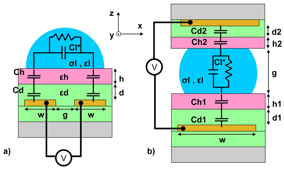
A model for LDEP was developed in [16,17,21,23]. This model assumed that an electrostatic force is able to break the capillary equilibrium of a droplet. Recently, Reference [22] has completed the model by introducing a global electromechanical energy paradigm to describe both EWOD and LDEP transduction. According to [22], the liquid displacement is generated thanks to a unified electromechanical force, which is the sum of the LDEP force and the EWOD force. Depending on the liquid properties and the applied frequency, one force becomes preponderant beyond the other. For low frequencies, the EWOD force is assumed to be preponderant, while for higher frequencies the LDEP force becomes higher. The frequency limit between the two forces has to be determined. In the literature, two LDEP device configurations can be found: the parallel-plate closed microfluidic device [Figure 1(b)] [24,25] and the single-plate open microfluidic device [Figure 1(a)] [26-28]. In order to clearly establish the advantages and drawbacks of both systems, those configurations will be compared in this study. On the one hand, the single plate device features two coplanar electrodes, separated by a gap g, patterned onto a substrate [Figure 1(a)]. The electrodes are covered by a dielectric layer and a thin hydrophobic layer (the dielectric layer can be itself hydrophobic preventing from an additional coating). The hydrophobic layer minimizes the effects of contact angle hysteresis and the static friction [20]. The electric field constrains the liquid in a semi circular profile centered in the inter-electrode gap [23]. On the other hand, the parallel-plate closed microfluidic device consists in applying a voltage between an electrode patterned onto the bottom substrate and a facing electrode located on the above plate [Figure 1(b)]. A hydrophobic layer covers a dielectric layer in both plates.
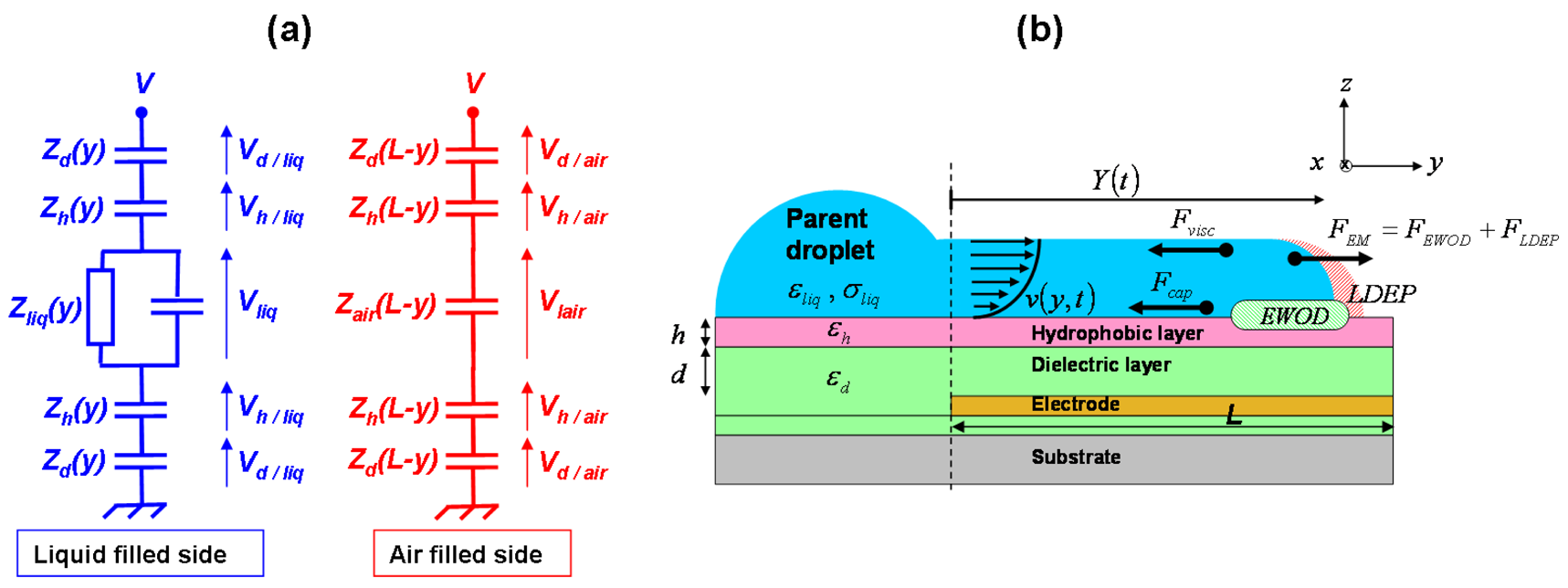
In order to calculate the electromechanical force, the system is modeled as an equivalent electrical circuit. The equivalent circuit is described in Figure 2(a). Each dielectric/hydrophobic layer is considered as a pure capacitance. The liquid, as an imperfect conductor, is modeled using a resistance and a parallel capacitance. Zd, Zh, Zliq and Zair represent respectively the impedance of the dielectric layer, of the hydrophobic layer, of the liquid and of the air in the case of a single-plate open microfluidic device. The model described in this paragraph is related to the single-plate open microfluidic device configuration. A comparison between both configurations is presented later on.
The equivalent RC electrical circuit model is illustrated on the Figure 2(a) where ε0, εd, εh, εliq and σliq, are respectively the vacuum permittivity, the dielectric layer permittivity, the hydrophobic layer permittivity, the dielectric constant and the conductivity of the liquid. d, h, w and g represent respectively the dielectric layer thickness, the hydrophobic layer thickness, the electrode width and the inter-electrode gap. K(k) is the complete elliptic integral of the first kind [20] and its modulus is . Lastly, the liquid is defined by a capacitance value Cliq and a conductance value gliq.
Based on the equivalent circuit model [Figure 2(a)], the electric potentials across each layer can be evaluated as a function of the RMS applied tension V and the complex impedances of the system. The total energy inside the system is deduced from the sum of each potential energy stored by each capacitance of the device [22]:
Considering all the capacitances inside the device, the total electromechanical force can now be expressed from the total energy derived with respect to the displacement direction (here according to the y-axis), and is given by:
An important parameter of LDEP actuation is the threshold frequency fc of the AC electric field. Since liquids conductivity varies according to the applied voltage AC frequency, fc represents a transition in the liquid behavior. When f ≪ fc, the liquid behaves as a conductor (the liquid is isopotential) and is predominantly moved by EWOD forces. On the contrary if f ≫ fc, the liquid behaves as a dielectric (electric field lines entering the liquid) and is moved using the LDEP forces. Literal expression of fc is thereby written as the ratio of the overall capacitance of the liquid filled side over its total conductance [left branch of equivalent electric circuit in Figure 2(a)].
Given the expression of both the electromechanical force and the other forces acting on the liquid (e.g., the capillary force Fcap and the viscous force Fvisc), the fundamental dynamic principle leads to a literal expression describing both the position and velocity of the liquid finger as a function of time [29]
At t = 0, in order to enable the liquid to move along the y direction, the electromechanical force must overcome the capillary forces: FEM > Fcap. This condition is theoretically satisfied as soon as the RMS applied voltage V is higher than a threshold voltage Vth given by Equation (15).
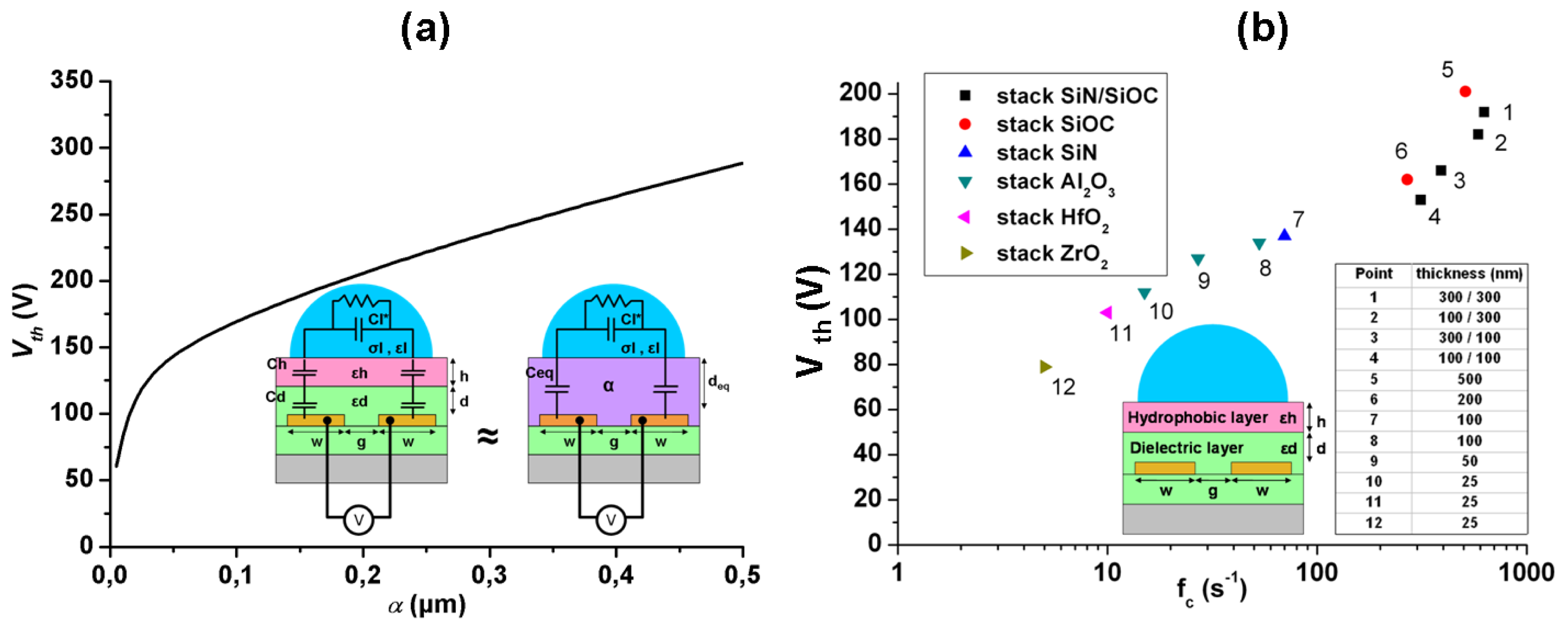
The expression (15) is associated to a typical stack composed of a dielectric layer (dielectric constant εd, thickness d) and a hydrophobic layer (dielectric constant εh, thickness h). The characteristic length α is introduced hereafter (17), and refers to the global dielectric/hydrophobic layer stack properties. As α is increasing, Vth is increasing satisfying the following Equation (16):
The previous expression is valid for chips composed of either two independent layers (an hydrophobic layer onto a dielectric layer) or a single layer featuring both dielectric and hydrophobic properties. The characteristic length α influence on the threshold voltage is inspected in Section 4.2.
The voltages across each layer, and therefore the electric fields contained in the layers or in the liquid, can be extracted from the previous LDEP model. Dielectric material has an inherent breakdown field. In order to prevent from dielectric breakdown voltage, the best matching in between dielectric and hydrophobic thicknesses can be adjusted by incorporating the electric field Eh (electric field across the hydrophobic layer) into the LDEP model. Indeed a linear relationship exists between thicknesses d and h as a function of Eh and the capacitances of the system. The relation (18) is valid for V = Vth and the hydrophobic layer potential in the air filled side is neglected in regard with its potential in the liquid filled side.
Zh* represents the hydrophobic layer impedance per unit of length and is expressed in Ω.m−1. The threshold voltage used to optimize the LDEP device is exposed in Equations (15) and (16) for a frequency threshold written in (13). Similarly to the work of Saeki et al. [30] about voltage reduction for EWOD actuation, the next section deals with the influence of the parameters to be optimized in order to achieve LDEP actuation with low voltage and low frequency.
3. Materials and Methods
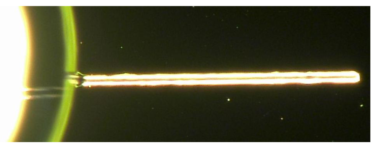
In order to benchmark this model, the effect of the geometry has been studied experimentally, with the electrode width w ranging from 3 to 20 μm and the inter-electrodes gap g ranging from 2 to 20 μm. Since the model discussed previously focuses on protrusion generation and not on its break up into droplets, simple parallel coplanar electrodes have been designed (Figure 3).
Chips have been manufactured by patterning 170 nm thick aluminum electrodes on a Si wafer (Pyrex), the latter being coated by a 100 nm Teflon-like passivating layer (on which DI water makes a contact angle θ = 110°).
The parent DI-water droplet is delivered with a manual 5 μL pipette directly on the electrodes. The experimental protocol consists in monitoring the threshold voltage which leads to a protrusion generation. All experiments have been done at 100 kHz.
4. Numerical and Experimental Results
This section presents results towards the minimization of the threshold required voltage Vth. We present in Section 4.1 theoretical and experimental results showing the electrodes geometry effects onto Vth, in Section 4.2 the theoretical effect of materials on Vth (i.e., the effect of the characteristic length α), in Section 4.3 the tradeoff in between the isolating layer(s) thickness reduction, and its electrical breakdown prevention is considered; and in Section 4.4 a comparison is carried out for both device microfluidic configurations.
4.1. Influence of Electrodes Dimensions
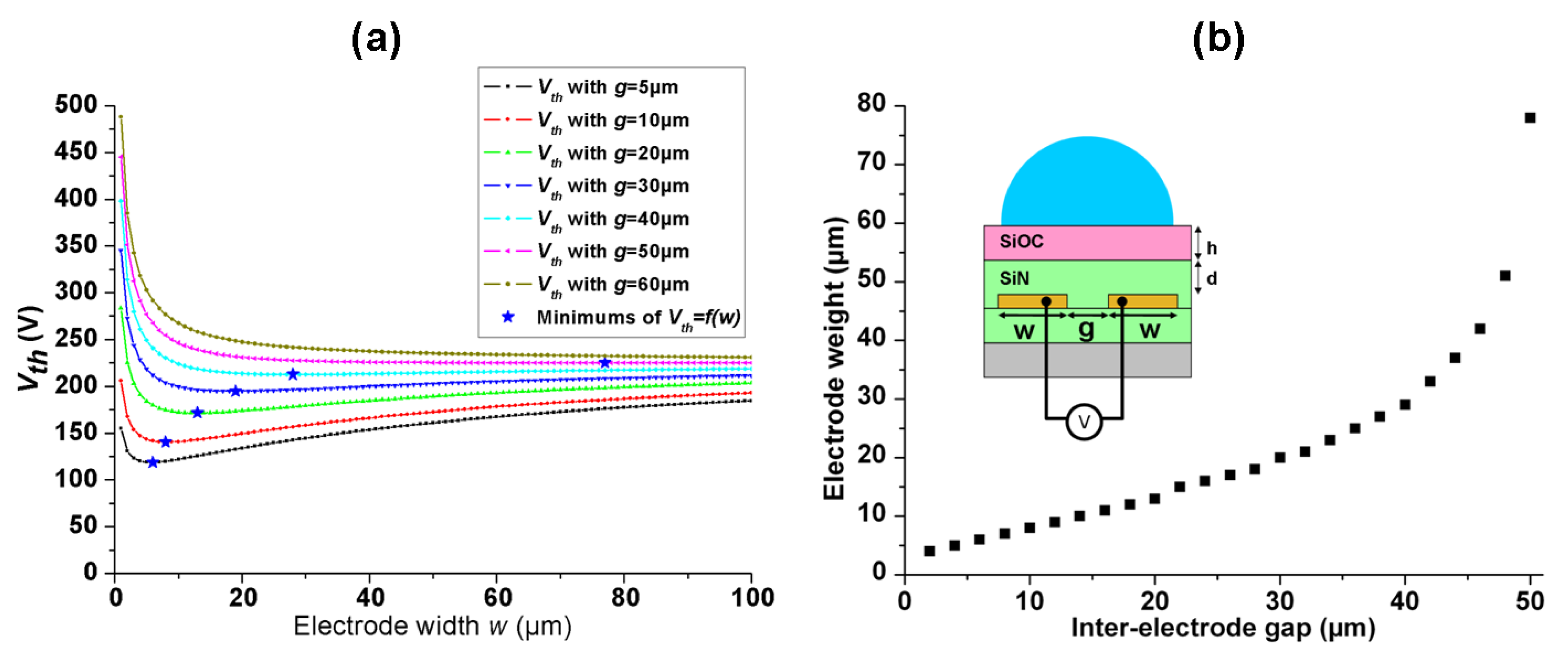
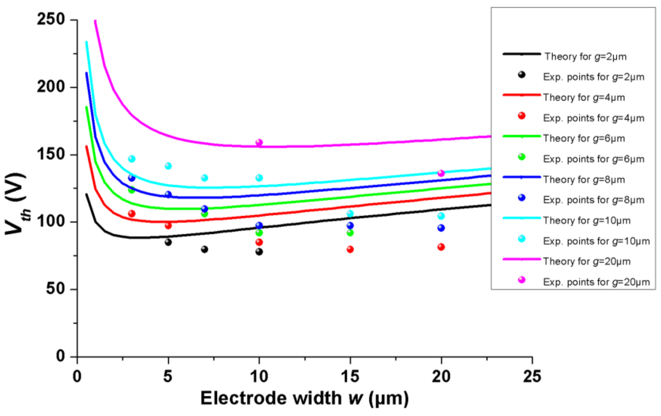
The electrode width w and the inter-electrodes gap g determine both the droplet size and the threshold actuation voltage Vth. Consequently, they have to be carefully designed according to the final application. Figure 4 shows that Vth can be reduced by setting properly the parameters (w;g) for a given liquid volume. Indeed, Figure 4(a) depicts Vth as a function of the electrode width w for a given inter-electrode gap g, highlighting the existence of a local minimum value. Figure 4(b) shows the relationship between w and g corresponding to these minima. The simulations in Figure 4 have been carried out for ultra-pure water (σliq = 6 × 10⁻⁶ S m−1 and εliq = 80), while setting the applied frequency value f one order of magnitude above the critical frequency (f = 10fc), in order to clearly actuate the liquid in the LDEP regime. These results show that Vth voltage can be set 25 V lower than its usual value providing w and g are properly adjusted. As one may see in Figure 4(a), we point out that this minimum does not always exist. Indeed, above a critical gap Vth is monotonically decreasing while increasing electrode width w. As a conclusion, Vth can be reduced by maximizing the ratio .
Simulation results have been compared with experimental data corresponding to the materials described in Section 3. Figure 5 shows a three-dimensional plot of simulated and measured Vth as a function of w and g The overall order of magnitude for experimental data is in fair agreement with the simulations: the percentage error can reach 40% for some experimental points. We may explain this discrepancy by omission in our model of the liquid contact angle θ dependence regarding the applied voltage into the capillary forces expression (presently θ value is fixed to π/2). A current work is in progress to address this issue. Other phenomena may also be included such as friction forces applied to the liquid at the three-phase contact line [31]. However, those additional studies, although relevant, will certainly increase the complexity of the model, which presently gives quite fair tendency
4.2. Influence of the Chips Constituent Materials on the Threshold Voltage Vth
For LDEP actuation, the constituent materials must be carefully chosen in order to minimize the threshold voltage Vth. The Vth value computed from Equation (16) has been plotted in Figure 6(a), for α ranging from 0.1 μm (corresponding to f = 10fc = 340 Hz) to 0.5 μm (corresponding to f = 10fc = 820 Hz). This curve confirms that the characteristic length α should be reduced (in other words, high global dielectric constant together with thin overall thickness is preferred) in order to lower Vth. From this consideration, using high-k materials as dielectric layer might be a promising strategy to pursue. Recently, Chang et al. [32] have demonstrated threshold voltage below 5 V for water droplet EWOD actuation, using Alumina Al2O3 (εAl2O3 ≈ 8) deposited by Atomic Layer Deposition (ALD) as a dielectric layer. Diagram in Figure 6(b) illustrate the expected Vth, fc parameters for representative materials. According to the material and the related process, the constituent layers thicknesses vary as indicated in the Figure 6(b) caption.
4.3. Influence of the Chips Constituent Materials on the Dielectric Breakdown Limit
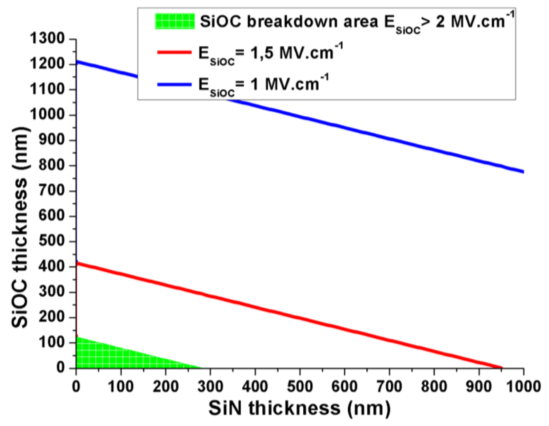
Despite its favorable effect on Vth, the dielectric layer thickness cannot be reduced below the dielectric breakdown limit. In a typical dielectric/hydrophobic stack with the same order of magnitude for each layer thickness h and d, the electric field across the hydrophobic layer is generally larger since it usually features a lower dielectric constant. This layer is consequently more sensitive to electrical breakdown, and its thickness h must be larger than a critical value that depends on both the hydrophobic material electrical breakdown field EBV and the dielectric thickness layer d. Based on the relationship (18), the Figure 7 highlights the SiOC layer breakdown area as a function of SiN and SiOC thicknesses, respectively d and h. The breakdown area represents the range of SiN and SiOC thicknesses that cause the dielectric breakdown of the SiOC layer. Such graph is particularly convenient to predict the electric field which can be supported for a given stack made of several dielectric materials.
4.4. Summary for the Single-Plate Open Microfluidic Device
In previous paragraphs, w and g are determined by the targeted droplets volume and by relationships ensuring a minimal threshold voltage. As indicated in Equation (16), Vth and fc can be further decreased using high-K materials, such as aluminum oxide (εAl2O3 ≈ 8) or zirconium oxide (εZrO2 ≈ 20). Table 3 draws up a list of representative materials with the related LDEP parameters.
4.5. Comparison between the Single-Plate Open Microfluidic and the Parallel-Plate Closed Microfluidic Devices
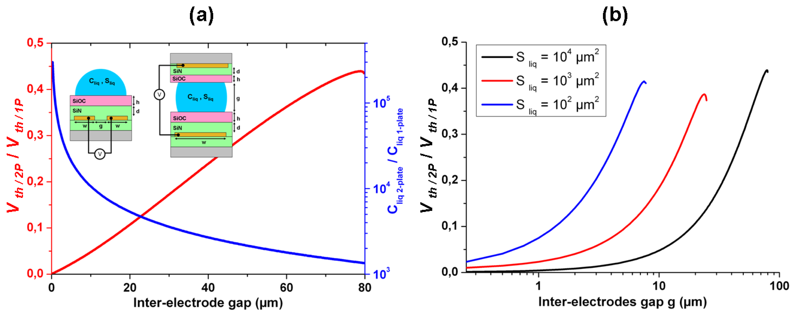
Both device configurations are associated to the same equivalent electrical circuit (Figure 1). The electromechanical model detailed in the Section 2 is valid also for the parallel-plate closed microfluidic device. Furthermore, if we assume a similar stack for each plate in terms of materials and thickness (as described in the Figure 1), the only difference between the two configurations is the expression of the liquid and air capacitance. Indeed, the layout of electrical field lines is different for the two cases, which induce significant variations for parameters such as the threshold voltage actuation. Here, the two capacitances in the single-plate open microfluidic and in the parallel-plate closed microfluidic will be evaluated and compared for a given liquid cross-section area (xz plane). The liquid cross-section area is for the single-plate open microfluidic device, and can be approximated as Sliq/2P = wg for the parallel-plate closed microfluidic device. Then each capacitance is expressed as a function of the liquid cross-section and the inter-electrode gap g width. Threshold voltage actuation Vth and critical frequency fc are also different according to the device configuration. For a given liquid cross-section area in the xz plane (orthogonal to the displacement direction), the threshold voltage in a single-plate device is about twice or more higher than in a parallel-plate device. To sum up, it is clear the two-plate configuration device is more favorable to decrease the LDEP voltage actuation.
The results shown in the Figure 8 agree with a T.B. Jones remark about the semi-circular profile of the liquid finger in an LDEP open device [23]. In the perpendicular plane to the liquid displacement, a force is applied in the liquid/air interface in the direction of the inter-electrode gap. Confining droplet into the inter-electrode gap requires energy, which does not lead to liquid actuation. Finally the parallel plate closed microfluidic device is more natural for the liquid because it effectively fills the inter-electrode gap.
5. Conclusion
Based on existing electromechanical models, this article suggests some design key rules to reduce both applied voltage and frequency for a LDEP actuation. The chip microfluidic configuration, its constituent layers dielectric properties, and the electrode design are the most important parameters to tune in order to reduce the actuation threshold voltage. Regarding the chip materials, numerical simulations highlighted that the layers should feature high dielectric constant together with low thickness, while preventing material dielectric breakdown and therefore electrolysis phenomenon. As an example, standard stacked layers composed of a 300 nm thick SiOC layer onto a 300 nm thick SiN layer leads to an expected actuation threshold voltage higher than 150 VRMS, while it is smaller than 50 VRMS for a single 50 nm thick Al2O3 or ZrO2 layer. These stacked layers theoretically prevent dielectric breakdown field since the electric fields across the layers do not exceed 2 MV cm−1 (see Table 3). In other words, the threshold voltage can be decreased by a factor of 2/3. Besides the constituent chip material influences, LDEP model highlighted that there are also optimized electrode design parameters (w,g) which reduce the threshold voltage. Some electrode design examples have been compared experimentally and theoretically, based on a single 100 nm thick Teflon-like passivating layer, in a single plate open microfluidic configuration. The experiments have shown fair agreement between the measured threshold voltage and the expected theoretical value. The maximum error is less than 40%. As far as the comparison between the fluidic configurations (open single-plate or closed parallel-plate) is concerned, the numerical results predict lower threshold voltages associated to the parallel-plate closed microfluidic device compared to the single-plate open microfluidic device.


| Parameter | Value | Units | Sources |
|---|---|---|---|
| g | 4–40 | μm | Microscope |
| w | 3–20 | μm | Microscope |
| h | About 100 | nm | Process duration |
| εh | 2.1 | unitless | Literature |
| σDI water | 60 × 10−6 | S m−1 | Conductimeter |
| Liquid section | 102 μm2 | 104 μm2 | |||||||||
|---|---|---|---|---|---|---|---|---|---|---|---|
| Material and thickness (nm) | (w;g) (μm) | fc (Hz) | Vth (V) | FEm (μN) | Ed/Eh(MV.cm−1) | (w;g) | fc | Vth | Fem | Ed/Eh | |
| SiN 300/SiOC 300 | (9;2) | 960 | 155 | 2.2 | 0.6/1.4 | (17.5;15) | 673 | 206 | 5.5 | 0.6/1.3 | |
| SiN 300/SiOC 100 | (8;4) | 762 | 133 | 2.2 | 0.8/1.8 | (15.5;19) | 485 | 187 | 5.5 | 0.7/1.6 | |
| SiN 100/SiOC 300 | (8.5;3) | 890 | 147 | 2.2 | 0.7/1.6 | (16.5;17) | 604 | 199 | 5.5 | 0.6/1.4 | |
| SiN 100/SiOC 100 | (7;6) | 616 | 124 | 2.2 | 1.0/2.2 | (14.5;21) | 358 | 175 | 5.4. | 0.8/1.9 | |
| SiOC 500 | (9;2) | 998 | 164 | 2.2 | 1.4 | (18.5;13) | 722 | 209 | 5.5 | 1.2 | |
| SiOC 200 | (7.5;5) | 723 | 131 | 2.2 | 2 | (14.5;17) | 463 | 176 | 5 | 1.7 | |
| SiN 100 | (6.5;7) | 286 | 101 | 2.1 | 1.3 | (17.5; 15)* | 131 | 128 | 4.5 | 0.9 | |
| Al2O3 100 | (7.5;5) | 235 | 90 | 2.1 | 1 | (17.5;15)* | 106 | 119 | 4.1 | 0.8 | |
| Al2O3 50 | (7.5;5)* | 130 | 78 | 1.8 | 1.1 | (17.5;15)* | 55 | 93 | 2.8 | 1 | |
| Al2O3 25 | (7.5;5)* | 68 | 62 | 1.3 | 1.4 | (17.5;15)* | 28 | 68 | 1.8 | 1.4 | |
| ZrO2 25 | (7.5;5)* | 23 | 38 | 0.7 | 0.8 | (17.5;15)* | 9 | 39 | 1 | 0.8 | |
Acknowledgments
The authors would like to thank ADVANTEST Corporation for donation of the 8-inches EB writer F5112 + VD01 equipment (at VLSI Design and Education Center, the University of Tokyo) that has been used to fabricate the photolithography masks.
| Nomenclature | ||
| Symbol Variables | Description | Units |
| ε0 | Vacuum permittivity | m−3 kg−1 s4 A2 |
| εd | Relative dielectric layer permittivity | dimensionless |
| εh | Relative hydrophobic layer permittivity | dimensionless |
| εliq | Relative liquid dielectric constant | dimensionless |
| σliq | Liquid electrical conductivity | S m−1 |
| w | Electrode width | m |
| g | Inter-electrode gap | m |
| d | Dielectric layer thickness | m |
| h | Hydrophobic layer thickness | m |
| Cd | Dielectric layer capacitance | F |
| Ch | Hydrophobic layer capacitance | F |
| Cair | Surrounding air capacitance | F |
| Cliq | Liquid capacitance | F |
| gliq | Liquid conductance | S |
| Zd | Dielectric layer impedance | Ω |
| Zh | Hydrophobic layer impedance | Ω |
| Zair | Air area impedance | Ω |
| Zliq | Liquid impedance | Ω |
| Sliq | Liquid cross section area | m2 |
| γLG | Liquid-gaz surface tension | N m−1 |
| f | Applied frequency | Hz |
| ω | Applied pulsation | s−1 |
| V | Applied voltage | V(RMS) |
| fc | Critical frequency | Hz |
| Vth | Threshold voltage | V(RMS) |
| Ed | Dielectric layer Electric field | V m−1 |
| Eh | Hydrophobic layer Electric field | V m−1 |
References
- Cho, S.K.; Moon, H.; Kim, C.J. Creating, transporting, cutting, and merging liquid droplets by electrowetting-based actuation for digital microfluidic circuits. J. Microelectromechanical Syst. 2003, 12, 70–80. [Google Scholar]
- Pollack, M.G.; Shenderov, A.; Fair, R.B. Electrowetting-based actuation of droplets for integrated microfluidics. Lab Chip. 2002, 2, 96–101. [Google Scholar]
- Paik, P.; Pamula, V.K.; Pollack, M.G.; Fair, R.B. Electrowetting-based droplet mixers for microfluidic systems. Lab Chip 2003, 3, 28–33. [Google Scholar]
- Fouillet, Y.; Jary, D.; Chabrol, C.; Claustre, P.; Peponnet, C. Digital microfluidic design and optimization of classic and new fluidic functions for lab on a chip systems. Microfluid. Nanofluid. 2007, 4, 159–165. [Google Scholar]
- Mugele, F.; Baret, J.-C. Electrowetting: From basics to applications. J. Phys. Condensed Matter. 2005, 17, R705–R774. [Google Scholar]
- Hua, Z.; Rouse, J.L.; Eckhardt, A.E.; Srinivasan, V.; Pamula, V.K.; Schell, W.A.; Benton, J.L.; Mitchel, T.G.; Pollack, M.G. Multiplexed real-time polymerase chain reaction on a digital microfluidic platform. Anal. Chem. 2010, 82, 2310–2316. [Google Scholar]
- Wheeler, A.R.; Moon, H.; Kim, C.-J.; Loo, J.; Garrell, R.L. Electrowetting-based microfluidics for analysis of peptides and proteins by matrix-assisted laser desorption/ionization mass spectrometry. Anal. Chem. 2004, 76, 4833–4838. [Google Scholar]
- Kang, K.H.; Kang, I.S.; Lee, C.M. Wetting tension due to coulombic interaction in charge-related wetting phenomena. Langmuir. 2003, 19, 5407–5412. [Google Scholar]
- Srinivasan, V.; Pamula, V.K.; Fair, R.B. An integrated digital microfluidic lab-on-a-chip for clinical diagnostics on human physiological fluids. Lab Chip 2004, 4, 310–315. [Google Scholar]
- Moon, H.; Cho, S.K.; Garrell, R.L.; Kim, C.-J. Low voltage electrowetting-on-dielectric. J. Appl. Phys. 2002, 92, 4080. [Google Scholar]
- Kang, K.H. How electrostatic fields change contact angle in electrowetting. Langmuir 2002, 18, 10318–10322. [Google Scholar]
- Park, J.K.; Lee, S.J.; Kang, K.H. Fast and reliable droplet transport on single-plate electrowetting on dielectrics using nonfloating switching method. Biomicrofluidics 2010, 4, 2–9. [Google Scholar]
- Fair, R.B. Digital microfluidics: Is a true lab-on-a-chip possible? Microfluid. Nanofluid. 2007, 3, 245–281. [Google Scholar]
- Quilliet, C.; Berge, B. Electrowetting: A recent outbreak. Curr. Opin. Colloid. Interface S. 2001, 6, 34–39. [Google Scholar]
- Chatterjee, D.; Hetayothin, B.; Wheeler, A.R.; King, D.J.; Garrell, R.L. Droplet-based microfluidics with nonaqueous solvents and solutions. Lab Chip 2006, 6, 199–206. [Google Scholar]
- Jones, T.B. On the relationship of dielectrophoresis and electrowetting. Langmuir 2002, 18, 4437–4443. [Google Scholar]
- Jones, T.B.; Fowler, J.D.; Chang, Y.S.; Kim, C.-J. Frequency-based relationship of electrowetting and dielectrophoretic liquid microactuation. Langmuir 2003, 19, 7646–7651. [Google Scholar]
- Kumemura, M.; Yoshizawa, S.; Collard, D.; Fujita, H. Droplet formation and fusion for enzyme activity measurement. VLSI Design 2009, 813–816. [Google Scholar]
- Kaler, K.; Prakash, R.; Chugh, D. Liquid dielectrophoresis and surface microfluidics. Biomicrofluidics 2010, 4, 1–17. [Google Scholar]
- Ahmed, R.; Jones, T.B. Dispensing picoliter droplets on substrates using dielectrophoresis. J. Electrostat. 2006, 64, 543–549. [Google Scholar]
- Jones, T.B. Dynamics of dielectrophoretic liquid microactuation. Available online: www.ece.rochester.edu/∼jones/ (accessed on 18 May 2011).
- Chatterjee, D.; Shepherd, H.; Garrell, R.L. Electromechanical model for actuating liquids in a two-plate droplet microfluidic device. Lab Chip 2009, 9, 1219–1229. [Google Scholar]
- Jones, T.B.; Gunji, M.; Washizu, M.; Feldman, M.J. Dielectrophoretic liquid actuation and nanodroplet formation. J. Appl. Phys. 2001, 89, 1441. [Google Scholar]
- Chiu, C.-P.; Chen, W.-J.; Fan, S.-K. Enhanced droplet mixer by LDEP on spiral microelectrodes. Design 2007, 951–954. [Google Scholar]
- Fan, S.-K.; Chen, W.-J.; Linm, T.-H.; Wangm, T.-T.; Linm, Y.-C. Reconfigurable liquid pumping in electric-field-defined virtual microchannels by dielectrophoresis. Lab Chip 2009, 9, 1590–1595. [Google Scholar]
- Wee, B.; Kumemura, M.; Collard, D.; Fujita, H. Isolation of single DNA molecule in a picolitre-sized droplet formed by liquid. Analysis. 2008, 36–38. [Google Scholar]
- Wang, K.-L.; Jones, T.B.; Raisanen, A. DEP actuated nanoliter droplet dispensing using feedback control. Lab Chip 2009, 9, 901–909. [Google Scholar]
- Prakash, R.; Paul, R.; Kalerm, K. Liquid DEP actuation and precision dispensing of variable volume droplets. Lab Chip 2010, d, 3094–3102. [Google Scholar]
- Wang, K.-L.; Jones, T.B.; Raisanen, A. Dynamic control of DEP actuation and droplet dispensing. J. Micromech. Microeng. 2007, 17, 76–80. [Google Scholar]
- Saeki, F.; Baum, J.; Moon, H.; Yoon, J.-Y.; Kim, C.-J.; Garrell, R.L. Electrowetting on dielectrics (EWOD): reducing voltage requirements for microfluidics. Polym. Mater. Sci. Eng. 2001, 85, 12–13. [Google Scholar]
- Blake, T.D.; Clarke, A.; Stattersfield, E.H. An investigation of electrostatic assist in dynamic wetting. Langmuir 2000, 16, 2928–2935. [Google Scholar]
- Chang, J.H.; Choi, D.Y.; Han, S.; Pak, J.J. Driving characteristics of the electrowetting-on-dielectric device using atomic-layer-deposited aluminum oxide as the dielectric. Microfluid. Nanofluid. 2009, 8, 269–273. [Google Scholar]
© 2011 by the authors; licensee MDPI, Basel, Switzerland. This article is an open access article distributed under the terms and conditions of the Creative Commons Attribution license (http://creativecommons.org/licenses/by/3.0/).
Share and Cite
Renaudot, R.; Agache, V.; Daunay, B.; Lambert, P.; Kumemura, M.; Fouillet, Y.; Collard, D.; Fujita, H. Optimization of Liquid DiElectroPhoresis (LDEP) Digital Microfluidic Transduction for Biomedical Applications. Micromachines 2011, 2, 258-273. https://doi.org/10.3390/mi2020258
Renaudot R, Agache V, Daunay B, Lambert P, Kumemura M, Fouillet Y, Collard D, Fujita H. Optimization of Liquid DiElectroPhoresis (LDEP) Digital Microfluidic Transduction for Biomedical Applications. Micromachines. 2011; 2(2):258-273. https://doi.org/10.3390/mi2020258
Chicago/Turabian StyleRenaudot, Raphaël, Vincent Agache, Bruno Daunay, Pierre Lambert, Momoko Kumemura, Yves Fouillet, Dominique Collard, and Hiroyuki Fujita. 2011. "Optimization of Liquid DiElectroPhoresis (LDEP) Digital Microfluidic Transduction for Biomedical Applications" Micromachines 2, no. 2: 258-273. https://doi.org/10.3390/mi2020258