1. Introduction
Freshwater is becoming more and more scarce and polluted; its consumption is increasing with population growth, causing a depletion of traditional sources [
1], while, at the same time, water contamination is becoming more and more severe. Climate changes are also playing an important role in the complex water issue [
1], causing drought in several places once rich of water. In order to balance the freshwater lack, in the last decades, untraditional sources have been studied and adopted. Among the most common technologies, like the desalinization of sea water, water extraction from air is becoming an interesting field of research. For example, studies of self-sustained systems have been developed, based on renewable energy use, and on hygroscopic solution absorbing moisture from the air in desert areas [
2]. The mass transfer can be increased by a special design of absorption strings [
3] when the water is captured by the saline solution and successively separated from it by a vacuum heating system, coupled with solar thermal collectors. In the early 2000s, a wide survey on atmospheric water vapor processing technologies was conducted. The work synthetizes different methodologies capable of extracting liquid water from air, by cooling a surface below the dew-point of air, by using desiccants or by inducing convection [
4]. The perspectives have been considered promising for future developments, taking into account adaption of commercial/industrial dehumidification technologies. Several patents regarding water extraction from humid atmosphere have been published in the last years [
5]. On one side, some inventions are based on the use of adsorbents, desiccants, and hygroscopic materials; they mainly address low humidity climate conditions [
6]. On the other side, the dehumidification process on a cooling coil is considered in various patents regarding whole HVAC systems or mobile systems. For example, mobile dehumidifier air-handling units have been studied to produce pure condensation water from moisture in the atmosphere, suitable for water production and drinking purposes [
7].
In the wide scenario of technical solutions for the water extraction from air, technologies based on a secondary use of the air conditioning systems may offer good perspectives, as HVAC systems are largely diffused everywhere. In summer conditions, the humidity and temperature control are carried out by air-cooling below the dew point, and a meaningful quantity of water is produced. Normally, such liquid is wasted, because of a lack of interest in recovering water and difficulties for the treatments needed for human consumption. Instead, water can be usefully employed to cover building needs, if an integrated system, which combines water extraction from air, equipped with specific water treatment and air conditioning, is studied. A method to characterize the total annual amount of the collected condensate, using correlations with local weather data parameters, and to evaluate the economics associated with a typical condensate collection system was experimented in 47 U.S. cities’ climatic conditions [
8]. The water collection from the central air conditioning unit, the storage of the recovered liquid in the tank, and its distribution for automatic irrigation is the subject of a patent [
9].
In this direction, some new indications have been promoted in recent times [
10] to increase environmental sustainability of the buildings in the Emirate of Dubai: new green building rules establish the need of condensate recovery in new buildings with a cooling load equal to or greater than 350 kW. The collected water can be used for irrigation, toilet flushing, or other onsite purposes but it should not come in contact with the human body.
Studies about combined and modified air conditioning units and dehumidifiers or double dehumidifiers providing air cooling as well as freshwater supply have been carried out and patents have been registered [
11]. Freshwater and drinking water can be produced by modifications of commercial air conditioning units of different sizes and capacities: they make water available by condensation of water vapor in the indoor and outdoor air surrounding the unit. This technology could be applied not only for the new buildings but also in air handling treatment unit (AHU) retrofitting [
12], even if the results must be evaluated accurately [
13], to reach economic advantages and energy sustainability high level of the process.
From the literature analysis, the effort to produce a great amount of water does not appear connected necessarily with the optimization of an air conditioning system and attention to its energy efficiency.
The aim of the current work is to develop the analysis of an integrated system, which combines not only water recovery and air conditioning, but also energy efficiency, by means of a tailored heat recovery system, in order to take a step in the sustainability direction. Some considerations were presented in [
14]. The integrated system design is referred to a new building, sized to supply the whole air conditioning demand. With the aim of obtaining very general results, the representative building chosen is a new hotel, shaped in a very simple and common configuration. The building thermal loads have been calculated under the climatic conditions of the Arab Emirates coast that represent the most suitable conditions for a strong need of air conditioning, because, especially during summer, temperature and humidity reach very high levels.
The following steps have been addressed:
analysis of the Arab Emirates coast weather, in order to find a representative climate;
new hotel main physical parameters definition;
energy loads and the water demand calculation;
preliminary system configuration for the case-study;
system optimization to produce maximum water flow;
calculated water extraction from air, which can be achieved with the integrated system, and the rate of water need covered.
Results will demonstrate that an integrated system achieves the required performances in air conditioning, as a traditional one, and, at the same time, can cover a meaningful rate of the building’s water demand. The main purpose of the present research is to expand the knowledge on this technology to show that the current system components allow obtaining a more efficient, energetically, and economically sustainable process than in the past.
One of the main contributions to the research in this field is represented by the system components sizing, aimed at the double purpose of air conditioning and water extraction, and jointed with the attention to the energy efficiency, to complete the scenario.
Further steps of the research will regard a comparison between the integrated system and a traditional air conditioning system, with the aim of quantifying integrated system convenience in terms of energy efficiency and cost effectiveness.
2. Climate Analysis
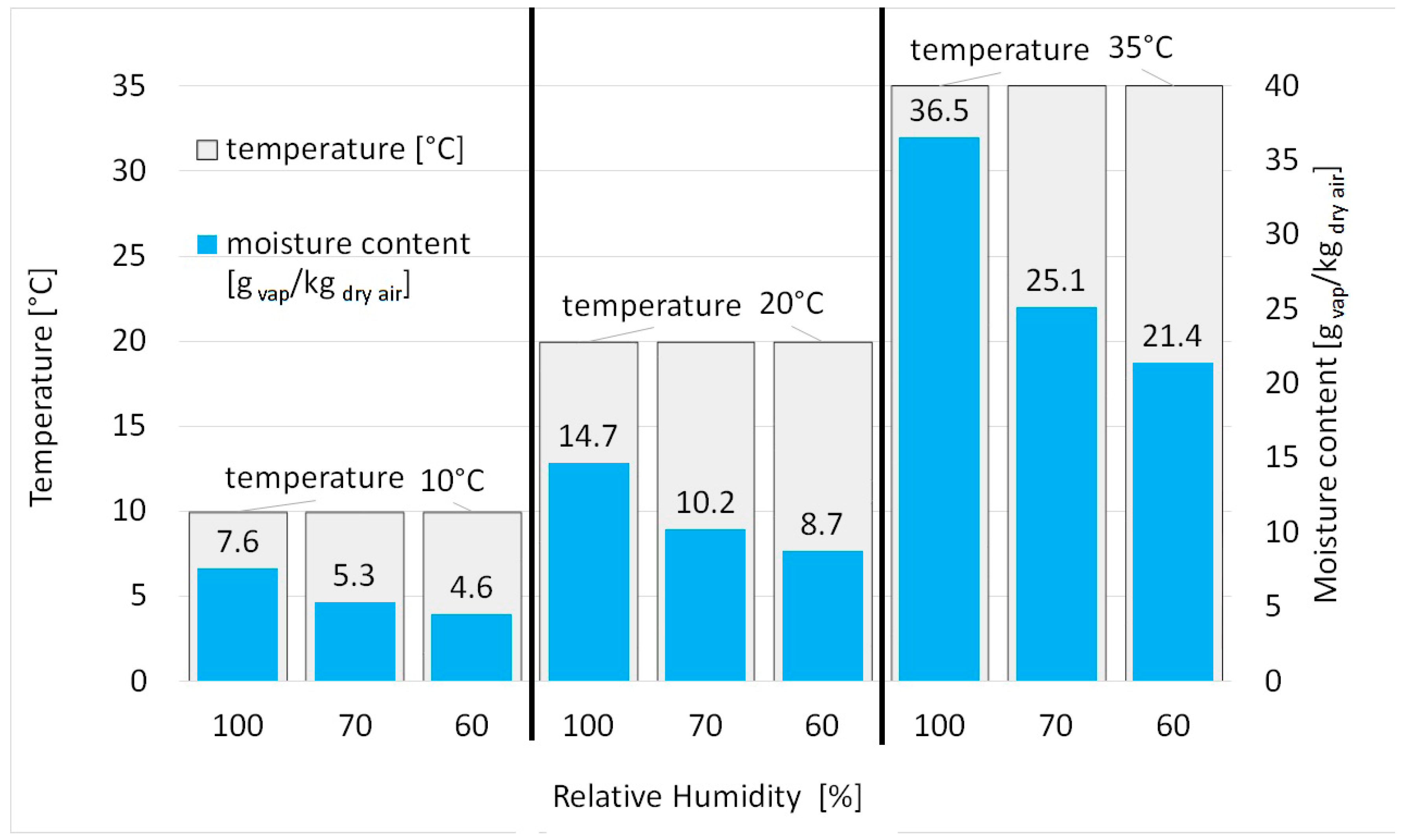
Water content in the air can be determined by means of three parameters: total atmospheric pressure, air temperature, and relative humidity. Taking into account the atmospheric pressure equal to 101,325 Pa, some values of the correspondence between temperature, moisture content, and Relative Humidity (RH), are represented in
Figure 1.
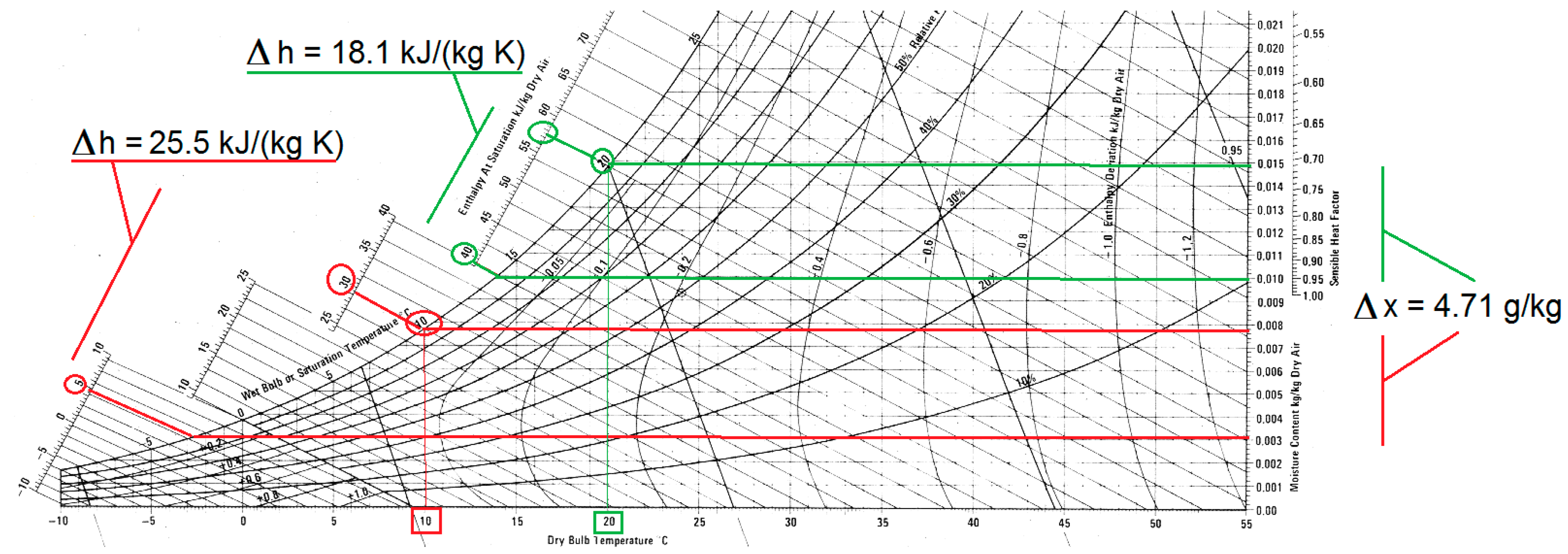
It is important to underline that the process to recover water from air requires less energy, when the hygrometric degree is high, as it can be easily ascertained from a psychrometric chart. If the saturation temperature increases, the saturation curve slope is higher, thus the specific energy required for water extraction is lower. In the following figure (
Figure 2), for example, the variation of specific enthalpy difference Δh is shown for the same water extraction, represented by the same difference of hygrometric degree Δx, in two saturation conditions. The first saturation condition is characterized by a dew temperature of 20 °C, the second one by a dew temperature of 10 °C.
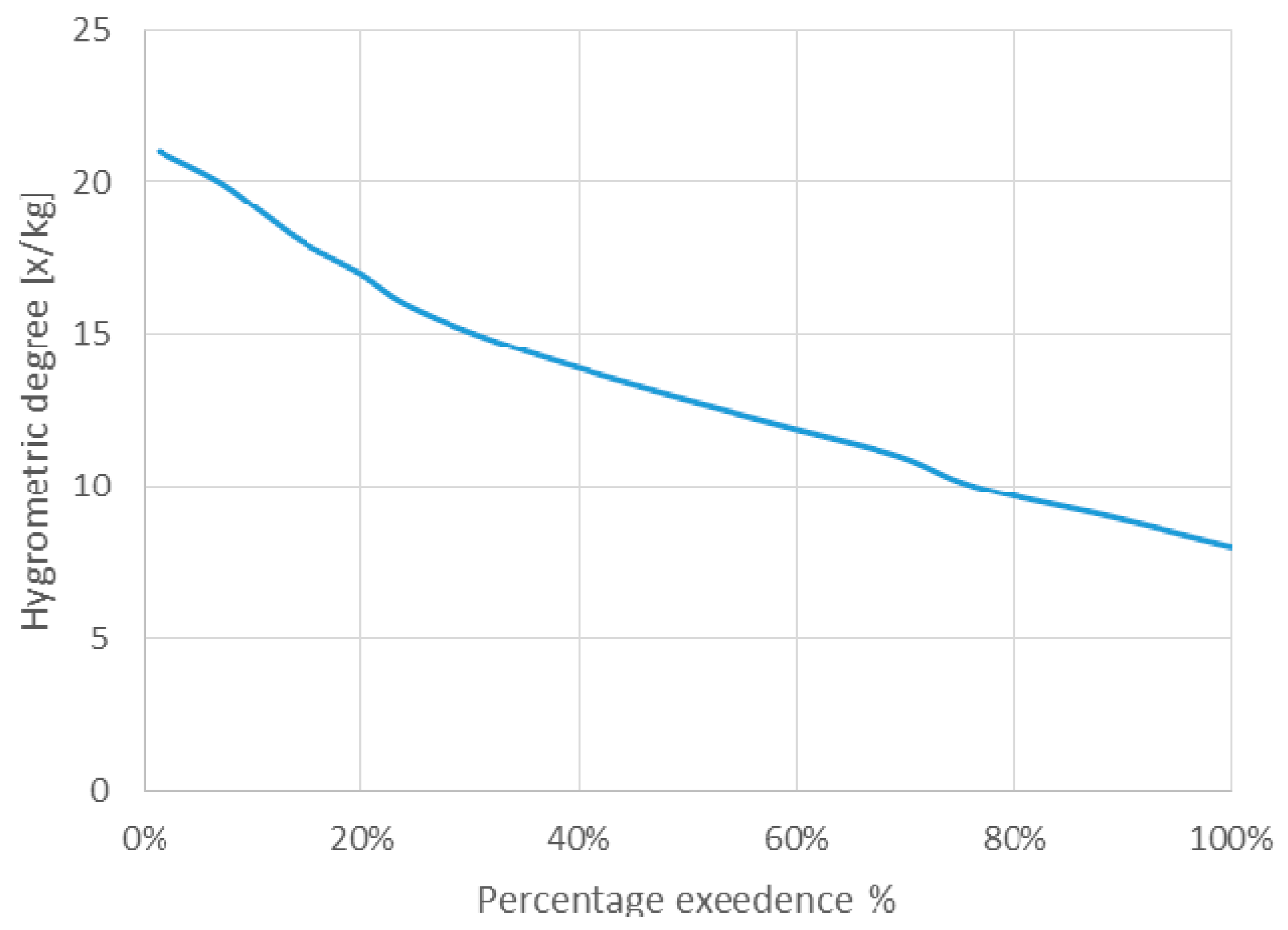
The most suitable climate for water extraction from air is hot and humid, when air is characterized by a state near the saturation curve and by a significant vapor content. In the present research, mean representative climatic conditions have been chosen, even if they are not the most suitable for the water extraction. According to the Köppen–Geiger classification, Arab Emirates costal climate can be indicated as a sub-tropical desert one, as it is characterized by medium–high relative humidity and high temperatures, but also by a lack of rainfalls. As the representative city for such a climate, Abu Dhabi was chosen for its location, almost in the middle of the coast, and for its climate, very similar to Dubai’s. In
Figure 3, the duration curve of the hygrometric degree, calculated for the whole year, shows that this climate is not optimal for water extraction from air. In fact, the vapor content in the air is lower than 15 g/kg of dry air for about the 70% of the time and it is near or lower 10 g/kg of dry air in more than the 25% of the cases. In
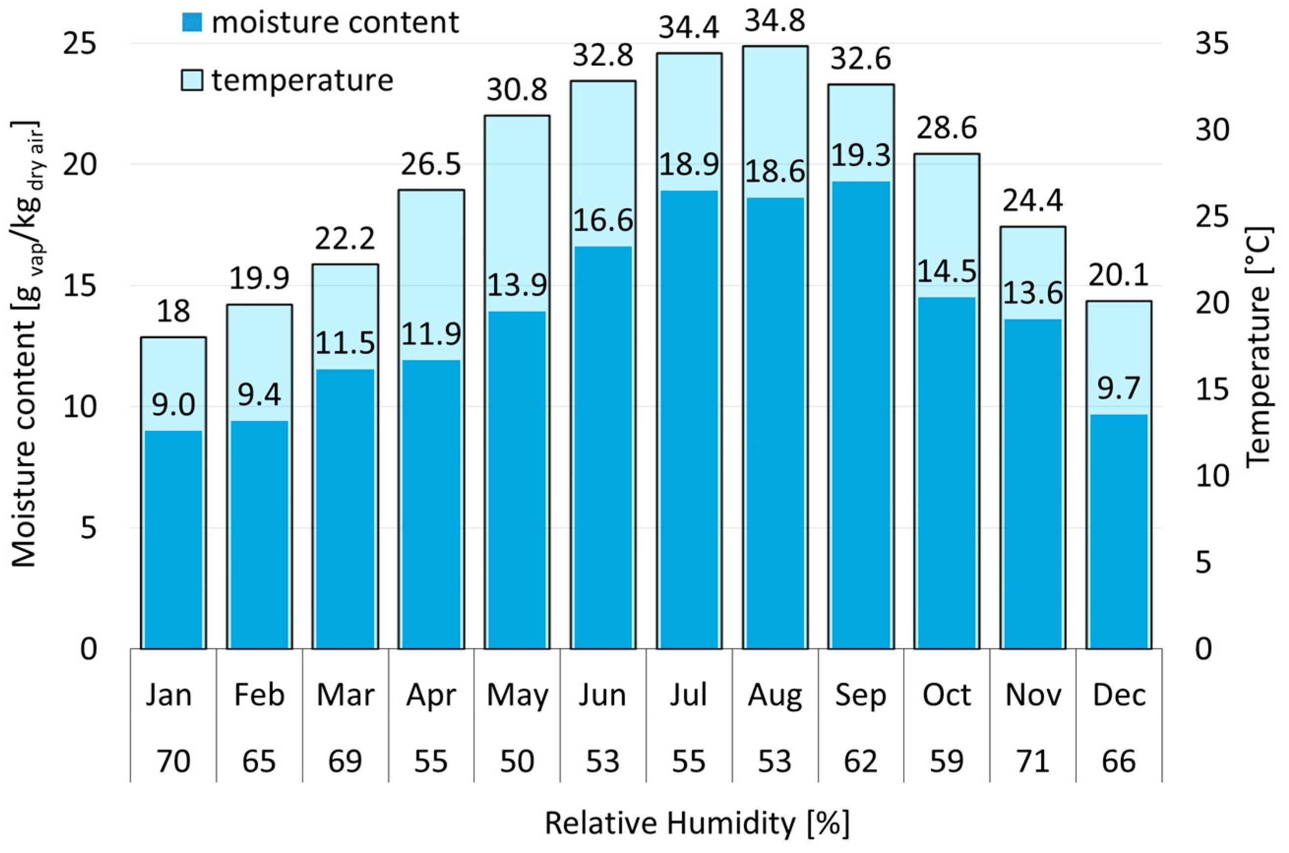
Figure 4, the average temperature, humidity, and moisture content is shown on a monthly basis.
The analysis was carried out on the basis of a statistic collection of more than 30 years of temperature and humidity data [
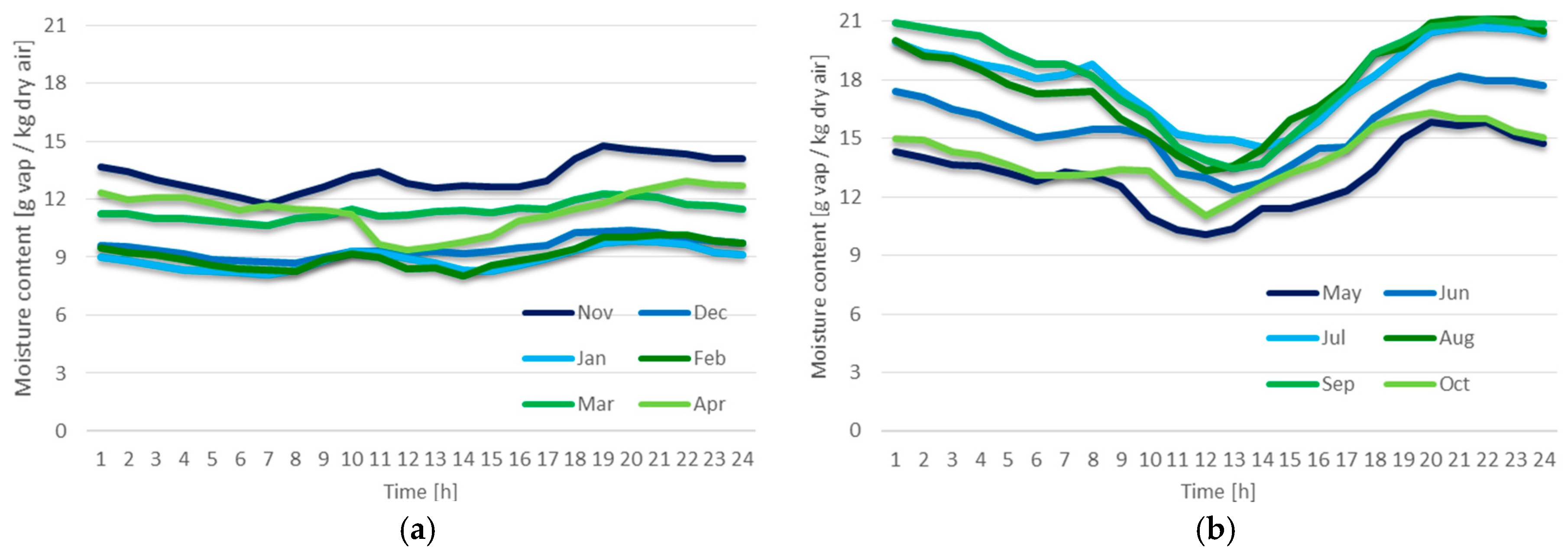
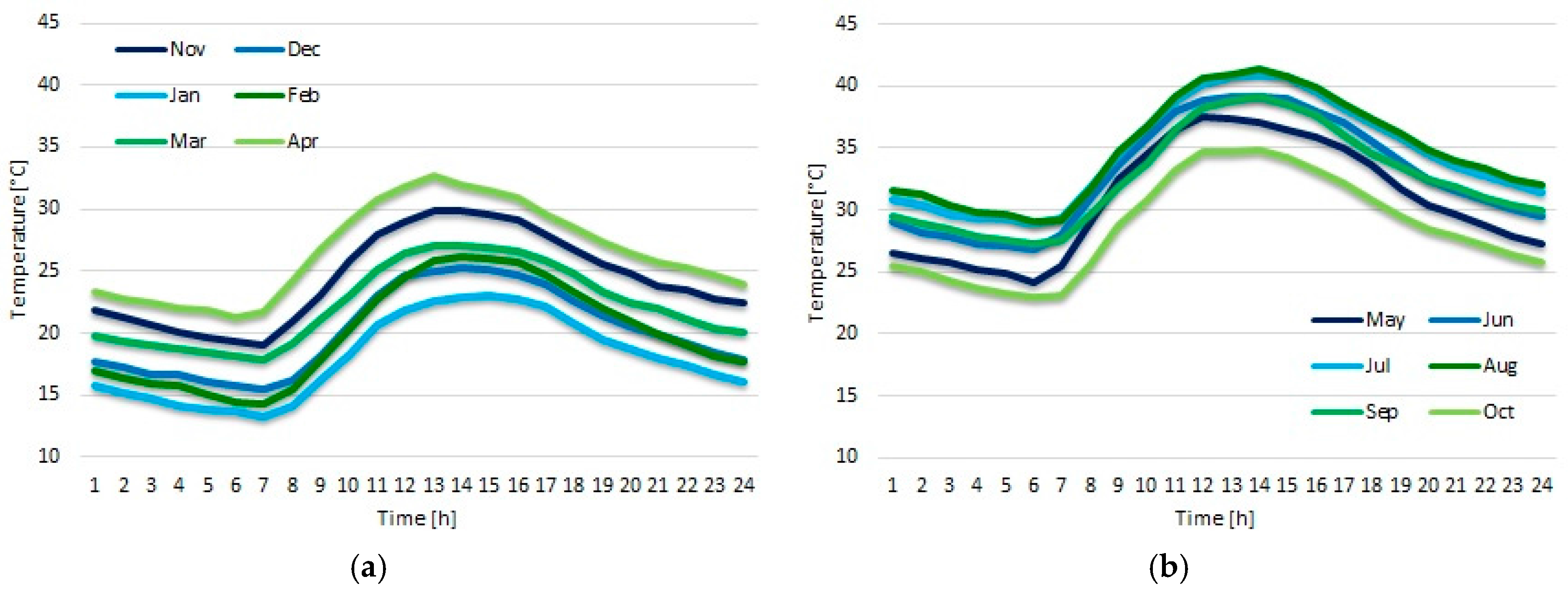
15]. The database reports, for the considered location, the typical average year calculated referring to such a collection. The year is described, month by month, by means of the average monthly day, calculated hour per hour. In other words, each month has 24 couples of values, temperature, and humidity, which represent the statistically average day of that month. The current study was performed taking into account all those data. In order to show the temperature and humidity behavior, the calculated monthly averages are shown in
Figure 5 and
Figure 6. Temperature and moisture content are shown for each month, from November to April (a) and from May to October (b): the two periods separately represent the months characterized by a maximum daily temperature respectively lower and higher than 35 °C. During three months—January, February, and December—temperatures are not so high: in fact, they are up to 20 °C on average and never over 26 °C (
Figure 5). In particular, it is possible to observe that January is the coldest one, as temperature is always under 23 °C. Anyway, during the other two months, the temperature is over 25 °C only for few hours. Those three months are also characterized by a low moisture content, as it is always below 10 g/kg of dry air (
Figure 6).
3. Case-Study Configuration and Load Calculation
In order to study the integrated system design, a representative building was needed. Since hotels need both air conditioning and large amounts of water, this kind of building was chosen for the current application. In particular, a medium-high rated hotel was considered, since in Abu Dhabi such a category of hotels is well represented.
Moreover, this kind of building, a hotel, is particularly meaningful for the local context, because of its impact on municipal water management. Actually, the tourism footprint in water consumption, at a local scale, is a major issue, because the direct daily water use, due to guests, is almost always higher than the domestic one. In the United Arab Emirates, average water consumption related to tourism is about 200 L for each guest per day, while domestic consumption is 174 L for every inhabitant per day [
16]. Moreover, in countries where tourism is an important economic resource, and there is lack of water, municipalities prefer to supply tourist accommodations instead of providing for the resident population. As tourism is not uniformly distributed in time, it is difficult to manage the municipal water supply, even more so if there is a large number of tourist accommodation buildings. Difficulties in aqueduct balancing, in water reserves, and in socio-political management, can arise. The integrated system, which can supply, beside air conditioning, a meaningful quantity of freshwater, can therefore represent an important help, or the solution for municipal water supply sustainability.
The hotel configuration is chosen in order to obtain very general results. The building is designed with 20 floors. The first five are intended for common areas, as shopping areas, reception halls, restaurants, and so on. The other floors house 20 private rooms each. Each room is dimensioned for two guests.
The nominal water supply for each room is 500 L/day, in compliance with local standards for medium-high hotels. Thus, the entire water need of the building is 150 m
3/day. The water supply amount represents not only guests’ consumption, but also all the other possible hotel needs, such as: kitchen uses, laundry, gardens watering, swimming pool water supply, and so on. Of course, such an amount is the maximum daily water demand. For the aim of the current paper, the hourly demand is not important, as the integrated system is equipped with water storage in the water treatment unit. It is interesting to underline that the water supply for each guest exceeds the daily water rate of the common Abu Dhabi citizen by more than the 43% [
16].
A 20 °C temperature and 60% RH, maintained during all the year, in the entire hotel, in compliance with local uses, represents the indoor climatic conditions.
Hotel geometry is very simple with a parallelepiped shape, two rows of rooms on each floor. Rooms are based on a common module characterized by:
The net conditioned volume is of 84 m3. A standard room is composed by a single module; suites and wider rooms are composed by two or four of them. Hotel design was principally oriented to define the physical parameters needed for the air conditioning sizing.
An average thermal insulation was assumed for the whole building, with a mean thermal transmittance of U = 0.4 W/(m
2K) for the opaque envelope, and of U = 2 W/(m
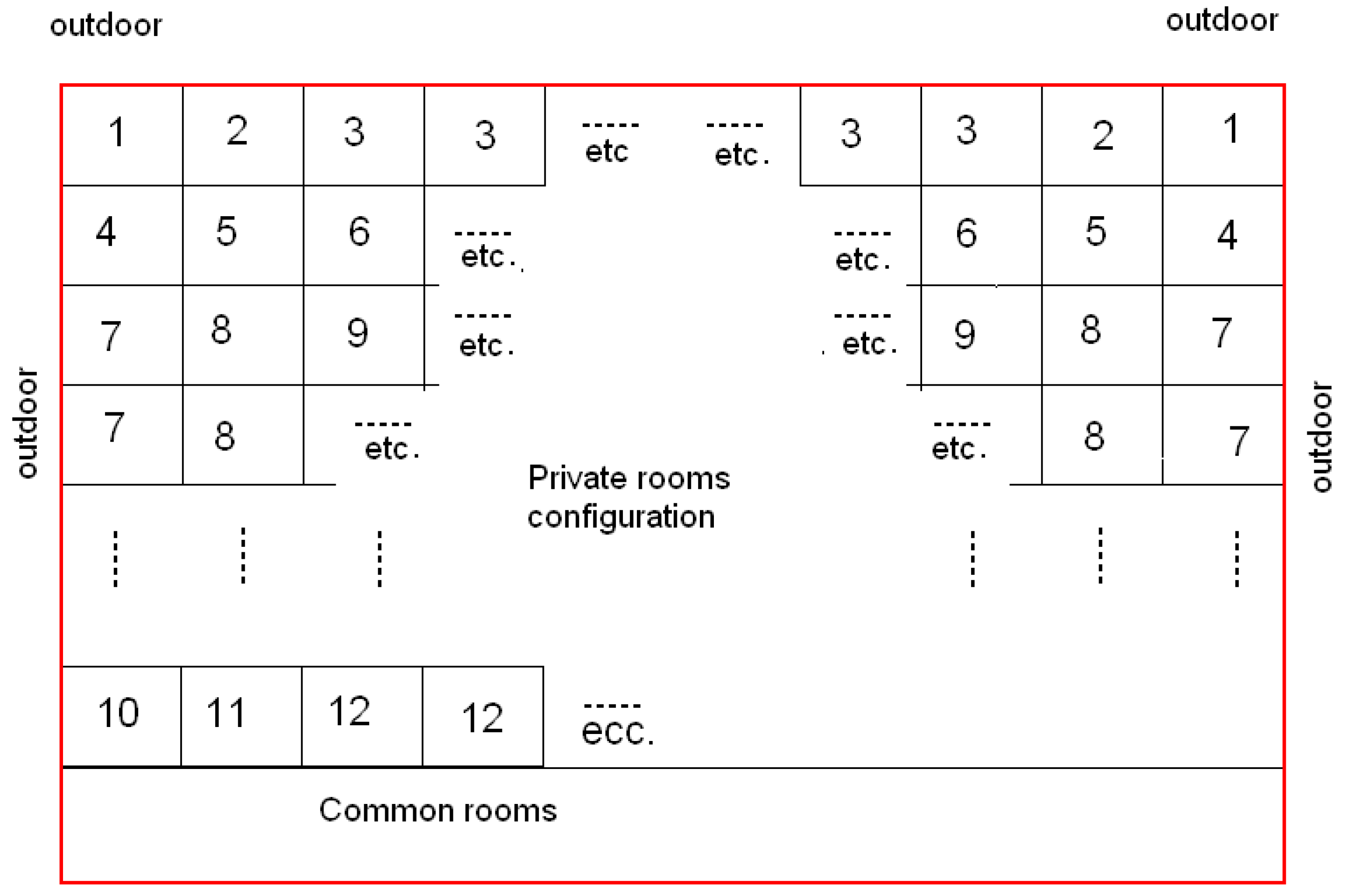
2K) for windows. In order to obtain more general results, a specific orientation for the hotel was not considered, thus radiation heat loads were taken into account by means of the sol-air temperature method. Heat losses for every room were determined under the hypothesis that all the other rooms were unoccupied and unconditioned, instead of the common zones, which were assumed to be conditioned. For calculations, air infiltration and heat loads due to occupation and electrical equipment were taken into account, while the extra flux towards the sky was neglected. In
Figure 7, room classification is represented, which was done referring to the number of external walls and of surfaces facing unconditioned rooms and corridors. There are 12 possible room configurations related to these geometrical features and boundary conditions. Heat loads were calculated in detail for each one of the 12 different conditions.
An example is considered in order to explain the meaning of the scheme in
Figure 7. The following features characterize rooms of the first kind (indicated with “1” in
Figure 7):
three external surfaces (two walls and ceiling) dividing the room from external air (btr = 1);
floor and a wall dividing the room from not conditioned rooms characterized by two external walls (btr = 0.6);
one wall that divides the room from conditioned aisle (btr = 0).
This kind of room is characterized by a 1394 W heat load, without taking into account loads due to occupation. In
Figure 7, the various configurations and their heat loads are summarized.
Calculation results give an average heat load value equal to 2.4 kW for each room. For the latent load calculation, persons and activities were considered. The total required cooling power was calculated as 3600 kW.
4. The Integrated System Configuration
The integrated system has been designed considering internal and external thermo-hygrometric parameters and the whole heat loads of the building. It is planned to consider two sections for the plant. The first one is dedicated to the air treatment of common areas. The second one, divided into five modules, delivers primary air for guests’ rooms (heat loads partially supported by fan-coil units).
4.1. Airflow
The outside air ratio for common areas was calculated referring to indications of the Italian national standard UNI 10339 “Air conditioning systems for thermal comfort in buildings—Generalities, classification, and requirements” (informative Appendix). Its reference values were taken into account also for guest rooms, assuming two guests in each room and an outside airflow of 11 L/(second person).
In
Table 1, values for the considered hotel are reported.
For the bar/breakfast room, the occupancy index was calculated as an average between the two indexes characterizing these two intended uses. The two restaurants are intended available also for external guests. Aisle occupancy index was calculated on the basis of rooms’ design occupancy.
Finally, the total fresh airflow rate results equal to 180,000 m3/h.
4.2. Design Parameters
Referring to the Abu Dhabi climatic data, the highest enthalpy value is reached in August, 88.9 kJ/kg, at a temperature of 34.9 °C and at RH of 59% (
Figure 8). The highest hygrometric degree, 21.14 g/kg, was calculated corresponding to a temperature of 34.9 °C and to a RH of 63% (in August, but an hour later than the enthalpy).
The design conditions for the integrated system were considered the following: enthalpy 90 kJ/kg, hygrometric degree 21.40 g/kg, corresponding to an external temperature of 35 °C and an RH of 60%.
Another important design parameter, for the integrated system, is the minimum saturation temperature allowed for water extraction. In the case of a machine, which produces water by means of a cooling cycle, such a limit is defined not only by the energy consumption, but also by the employed technology. In the current design, air cooling is performed by means of a water–air heat exchanger, not only to avoid R134a contamination of the air, but also to avoid the possible condensate contamination which can occur in case of pipes breaking. Oil is a dangerous substance as a very little quantity of it can immediately clog active carbon, reverse osmosis, and other kinds of membranes, which have to be parts of the water treatment unit, as will be described in the following
Section 4.6 Water Treatment Unit.
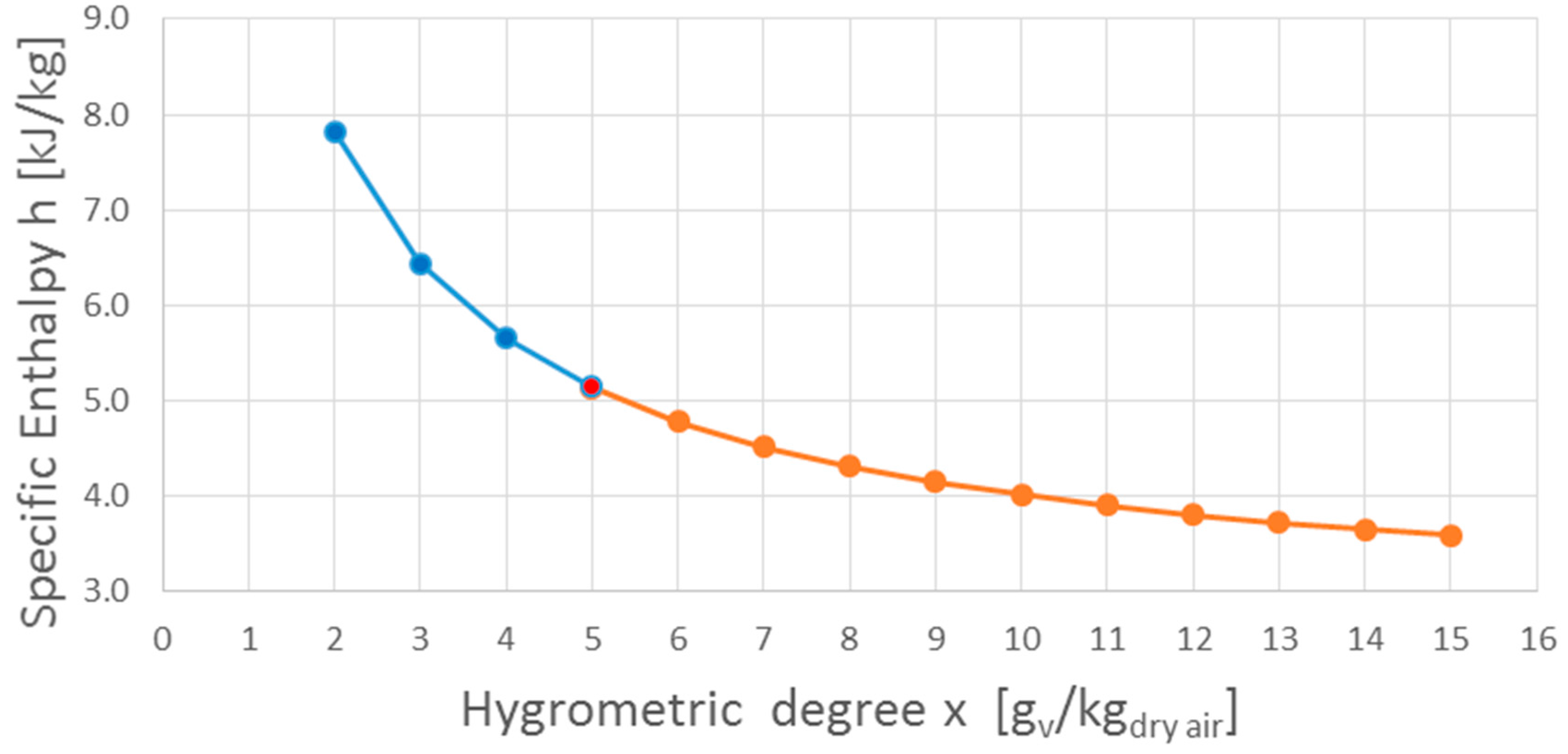
It was decided that only a few percentage points of (alimentary) ethylene glycol needed to be added to the cool water, in order to avoid lack of performance of the coil and also any kind of contamination of the produced water in case of pipes breaking. In these conditions, the minimum dew point temperature of the cooled air, achievable without problems of freezing, is 4 °C with a hygrometric degree of 5 g/kg. Such a threshold cannot be lowered without increasing the glycol content in water or considering a defrost circuit. This threshold is also energy effective. In the following graph,
Figure 9, the difference of specific enthalpy required to extract a gram of water from air is represented as function of the hygrometric degree, on the saturation curve, calculated in a range of dew point from 15 °C to −8 °C. The more the slope of the curve is marked, the more energy is required to extract the same quantity of water from air. It is evident that going to a hygrometric degree lower than 5 g/kg is very energy expensive.
4.3. Cooling Units
Different airflow amounts, for different environmental conditions, were analyzed in order to maximize the ratio between the achievable condensate quantity and the energy needed to obtain the liquid water. For the minimum dew point allowed of 4 °C, corresponding to a design limit of the hygrometric degree of 5 g/kgdry air, the optimal air flow of 30,000 m3/h was found.
We considered the study of a single HVAC module and the use of an appropriate number of modules for a more useful generalization of the results for other applications. Each module is dedicated to the treatment of 30,000 m3/h of air: the calculated cooling loads lead to a corresponding power of 600 kW (200 kW delivered by a heat recovery system and the rest supplied by the chiller unit, as shown below).
The total required cooling power calculated for common areas and private rooms is equal to 3600 kW and therefore the hotel will be provided with six modules of the same size. The aim was to cover a considerable quantity of water demand and the air conditioning needs of the hotel simultaneously. Another aim was also to employ a middle size module, easy to transport and to use in other different situations.
4.4. Main Design Characteristics
From the calculated energy needs and the considered climatic conditions, it is possible to assume the following prescriptions for the integrated system:
3600 kW of cooling power (where the power supplied by the chiller will be 2400 kW, while that supplied by the recovery equipment will be 1200 kW);
180,000 m3/h of treated air flow;
7 °C as minimum threshold for the air temperature in the inlet section of cooling unit;
2 °C the design inlet temperature of the chiller;
7 °C the design outlet temperature of the chiller.
Air coming from the water extraction circuit passes through the heat recovery system and then is used as fresh air for both common areas and private rooms.
4.5. System Configuration
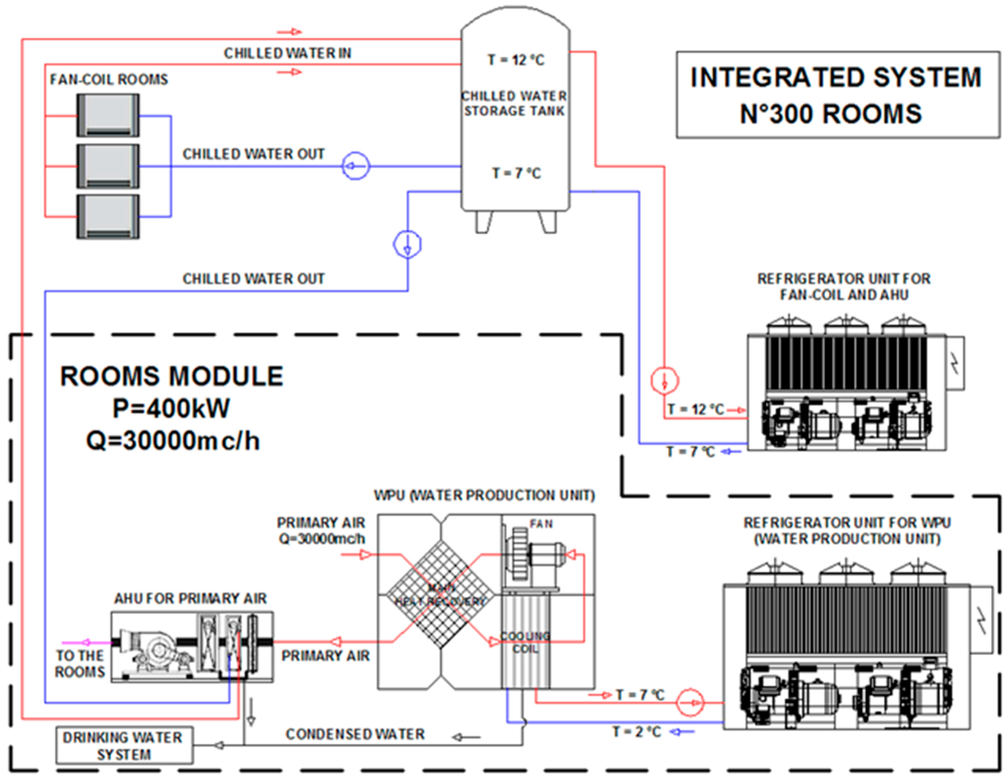
As said before, the system is composed by two sections, one for common areas, another for private rooms. In the following figure, this second one is represented. (
Figure 10).
The module dedicated to guests’ rooms was designed as follows:
- (a)
a heat recovery (h) unit, a cooling coil (cc), a fan: they represent the air treatment unit for the production of water (WPU);
- (b)
a cooling coil, a fan, a pump for the refrigerant circulation, a refrigeration unit that provides the air treatment unit: they characterize the air handling treatment unit (AHU).
The heat recovery system performs the external air pre-cooling, which can condensate a higher water ratio from air, with the same compression energy consumption. The outcoming air is very dry, thus, in design conditions, only a sensible post cooling is necessary in order to match neutral conditions. Moreover, it was calculated that such a system, if temperature is equal to or below 27 °C and relative humidity below 70%, the air coming from the WPU is equal or under neutral conditions (20 °C and 60% of relative humidity). In those cases, which occur 50% of the time taking into account the real yearly behavior of temperature and relative humidity, no further treatments, or only a post-heating, are required. Such a post-heating is carried out by means of condensation heat.
The system for private rooms is represented by AHU + fan-coils: the AHU handles only the primary air that is sent to the rooms in neutral conditions. No recirculated air flow is considered. Fan-coils maintain the set indoor temperature. The sensible heat load is charged to the fan-coils, while only latent heat is covered by supply air. In the common areas, the AHU also handles recirculated air, but only the primary air is treated by the WPU anyway.
Usually, the HVAC system is sized according to the worst conditions of external temperature and RH. In this case, however, the main target is the water production from air, and therefore the enthalpy of humid air should be the most representative physical parameter. In fact, with reference to the WPU, the mass flow rate of external air Q [m
3/h] and the outlet condition from the cooling coil, the total refrigerating power P
tot [kW] is calculated as:
where
ρ is the air density [kg/m3];
(hin-hr,1 − hout-hr,1) is the enthalpy variation of humid air in the inlet air side (side 1) of heat recovery [kJ/kg];
(hout-hr,1 − hout-cc) is the enthalpy variation of humid air in the cooling coil [kJ/kg];
Phr is the refrigerating power available by heat recovery [kW];
Pcc is the refrigerating power of the cooling coil [kW].
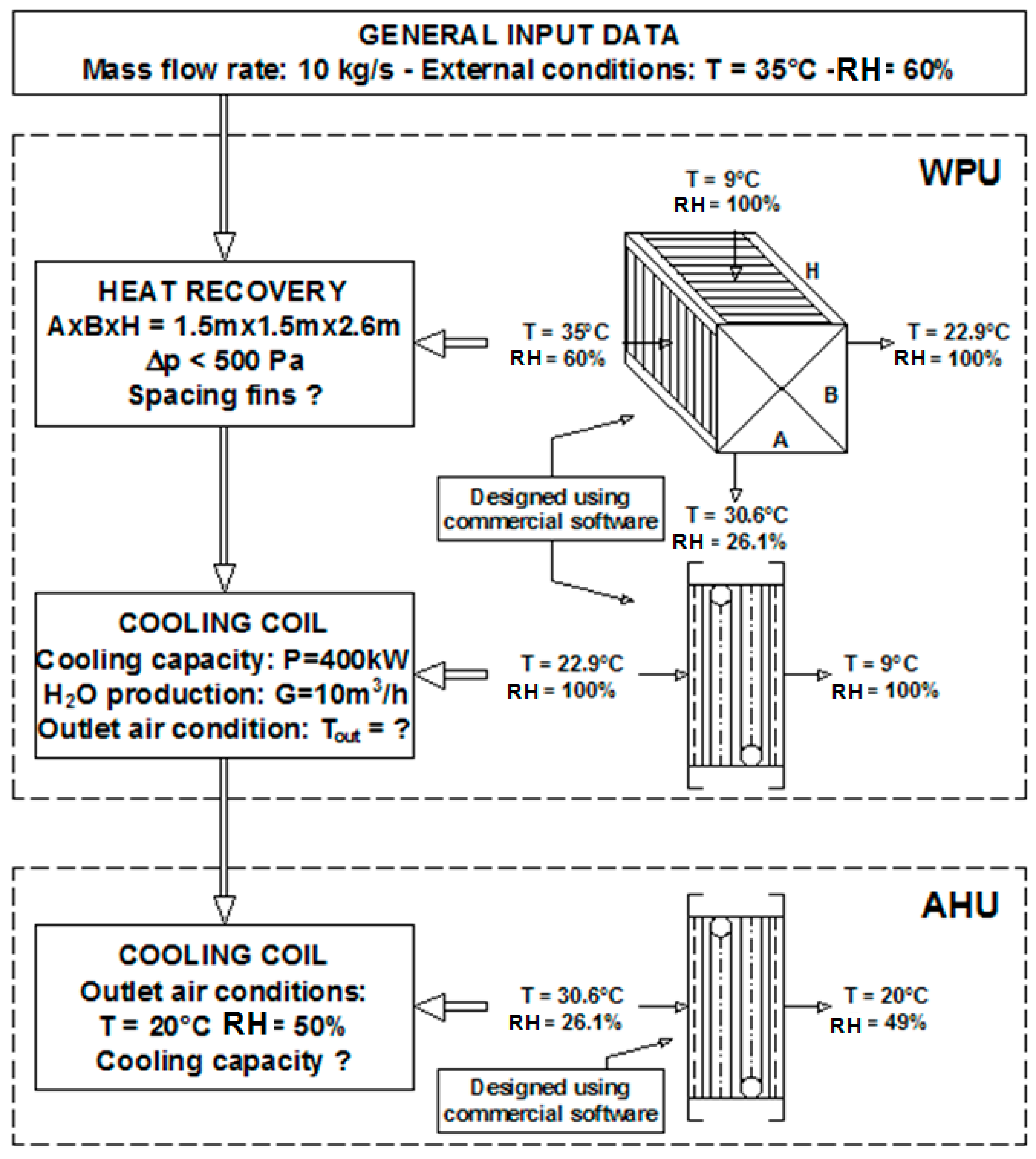
The single component sizing was carried out by using heat transmission characteristics given by coil suppliers. Those characteristics, semi empirically determined, are collected in databases which can be queried by means of a simple commercial software. A parametric analysis was conducted by varying the input data: it enabled definition of the overall architecture of the system. In particular, taking into account the design thermal loads and the air flow rates needed to ensure the thermo-hygrometric design parameters in all the rooms, a basic module for the dimensioning of the different components has been defined. The water production unit (WPU) has been structured with the purpose of maximizing the condensing water and, simultaneously, making available pre-treated air (already dehumidified) at the inlet of the air handling unit (AHU) (
Figure 11).
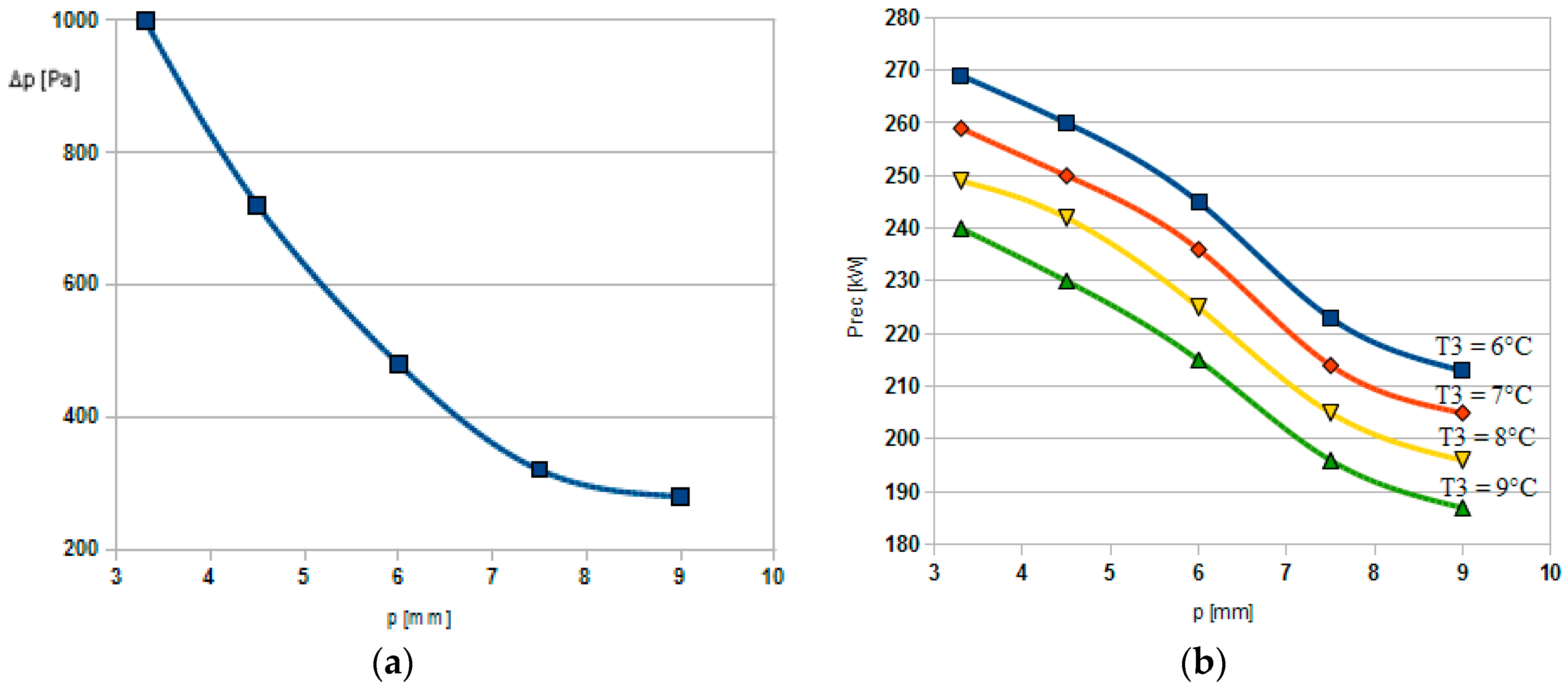
In particular, for each heat recovery geometry set, and fin spacing (path p = 3.3–4.5–6–7.5–9 mm), the inlet cooling coil temperature T
3 was varied (6–7–8–9 °C). This process can obtain the maximum heat recovery power, compatible with the limit of Δp
max = 500 Pa, to avoid fin deformation due to the pressure difference. In fact, reducing fin spacing, the heat recovery power increases but also the pressure difference. In
Figure 12a the increasing pressure difference Δp [Pa], related to the fin spacing, is shown for the analyzed configuration. In
Figure 12b, the inlet cooling coil temperature and the fin spacing influence on the heat recovery power P
rec [kW] show that this increases by 10 kW/°C in all the fin spacing configurations.
With a fixed heat recovery geometry (A = B = 1.5 m, H = 2.6 m), the conditions of the inlet air (side 1) are T
1-in = 35° C and RH
1-in = 60% (
Figure 11), whereas those in the input side 2 depend on the characteristics of the cooling coil (RH
2-in = 100%).
The air flow rate of Q = 30,000 m3/h in the side 1 of heat recovery, where the outside air is cooled, allows the outdoor air heating in the side 2. Taking into account the constraints on the pressure drops (Δpmax = 500 Pa), the configuration with a fin spacing of 6 mm is chosen. To define the air temperature leaving the cooling coil TB-out, it is necessary to take into account the constraints on the refrigerating power Pfrig (400 kW, calculated by a compromise between the cooling coil power, its dew-point temperature and the heat recovery power) and on water production (it is established a production of GH2O > 10 m3/day). To meet all the requirements simultaneously, it is calculated that TB-out = T2-in = 9 °C. In this case, it is in fact: Pfrig = 408 kW and GH2O = 12.3 m3/day.
The total refrigerating power of the WPU depends on the enthalpy of humid air at the outlet of cooling coil. With T
out-cc = 9 °C and RH = 100% it can be calculated that
With this refrigerating power, it is always possible to reach the exit temperature of the cooling coil because the outside air enthalpy (90.1 kJ/kg) is, reasonably, the maximum level.
External air conditions assumed represent the worst condition, taking into account the said statistic weather database.
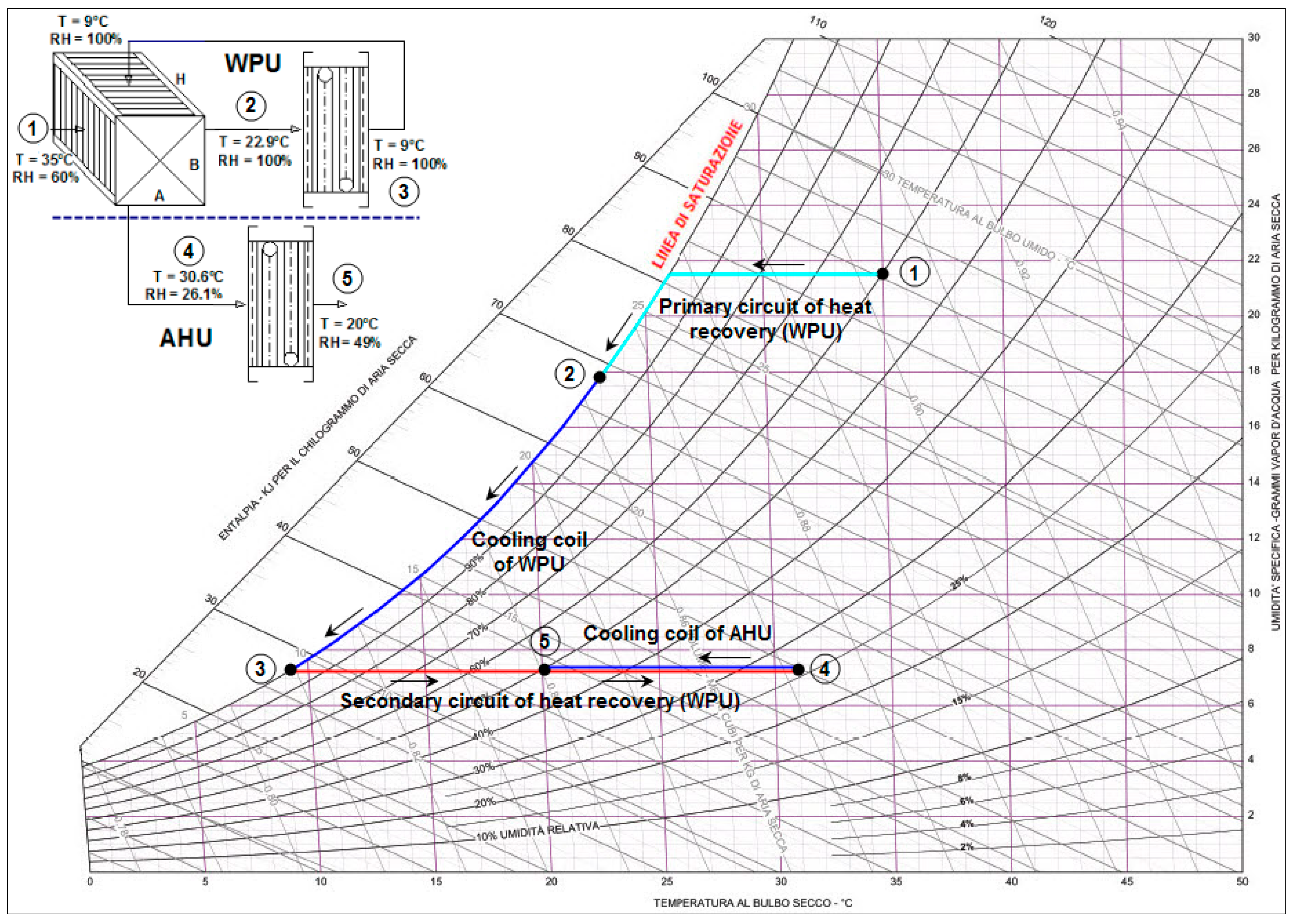
Figure 13 shows the thermodynamic transformations of the air in the primary and secondary circuits of the system.
4.6. Water Treatment Unit
An important part of the integrated system is the water treatment unit, which obtains drinking water from the condensate. Condensed water coming from a normal air conditioning system is not safe, nor pure, and it is not suitable for human consumption. As a matter of fact, in standard HVAC systems, air filters, heating coils, condensate collector tanks, pipes, and so on, are not thought in order to achieve any sterilization of the condensed water, nor its mineralization. Moreover, condensed water often may contain bacteria, viruses, ammonia, nitrates, nitrites, and other pollutants coming from air. Furthermore, as condensed water, for its nature, is very poor in minerals content, it could be hazardous for human consumption, even if it were pure [
17]. Therefore, the integrated system must consider those issues. All components expected to be in contact with water must be designed with certified materials, corrosion resistant and suitable for contact with food. The water treatment unit is considered complete with ultraviolet germicidal irradiation, a very strong multi filtration stadium, active carbon, and specific mineralization. By means of these treatments, the polluted condensate can become drinking water, suitable for human consumption. The present work considers the presence of this indispensable component even if its sizing is not here developed here, but it will be deepened in a further analysis.
5. Theoretical Water Production and Needs Covering Evaluation
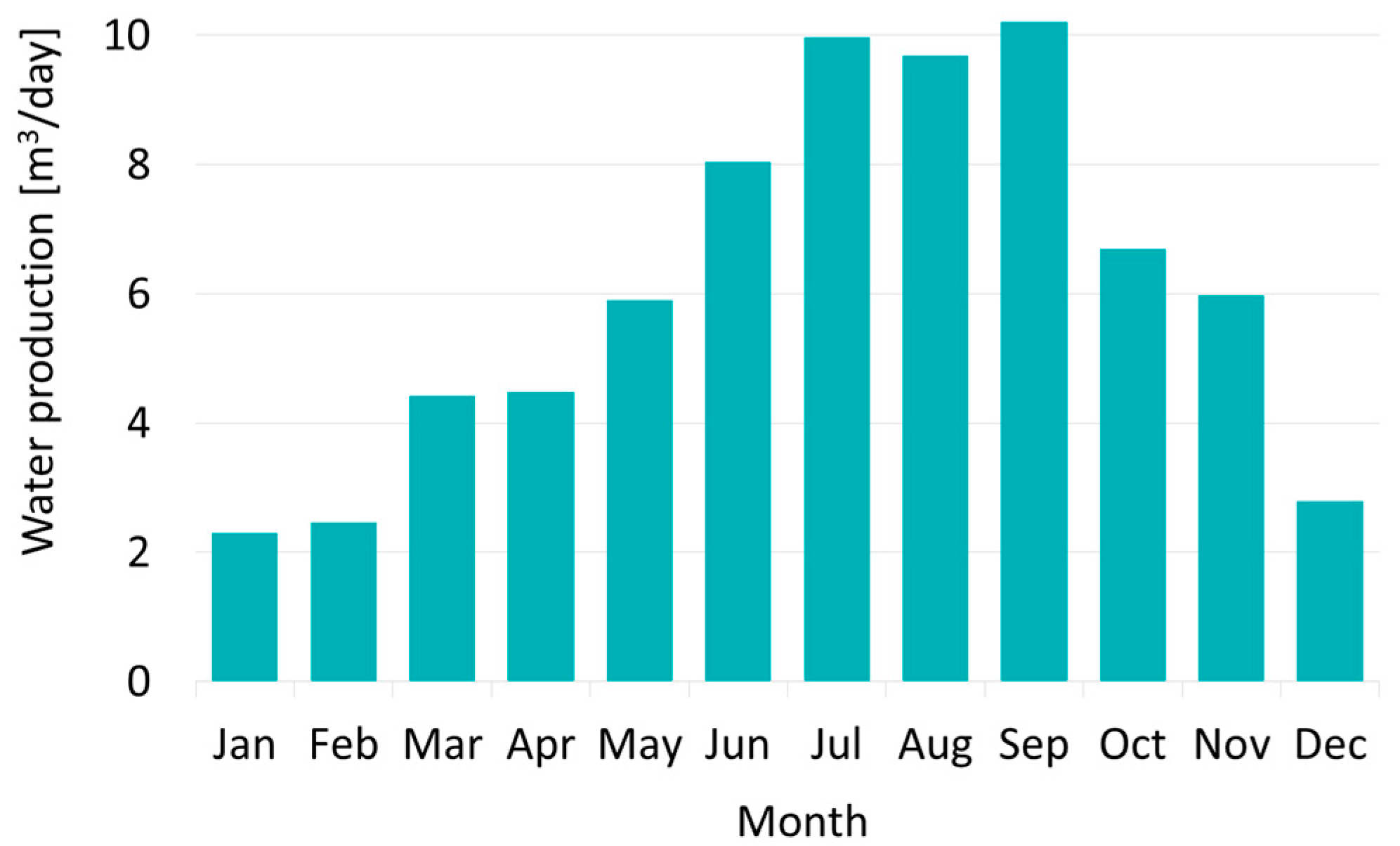
On the basis of the chosen weather conditions and the preliminary system design, an indicative calculation of the water which can be produced from air by a single module was possible. A simulation of the machine behavior based on hourly climatic data, of the average monthly day, was carried out, to guarantee an internal temperature of 20 °C and RH of 60% and to maximize water extraction: the results are shown in
Figure 14. The simulations were performed, neglecting transient conditions.
As expected during January, February, and December, water extracted from air is not obtained in very high quantities. Such limited water quantities are related, as said before, to the low vapor content of the air. Anyway, it is always possible to obtain at least more than 2 m3/day of water from each integrated system module. It is important to highlight that, during these months, the air conditioning loads could also be reduced. The maximum water production is achieved during June, July, August, and September. The peak in water extraction from air is in September when the daily production achieves 10.2 m3/day.
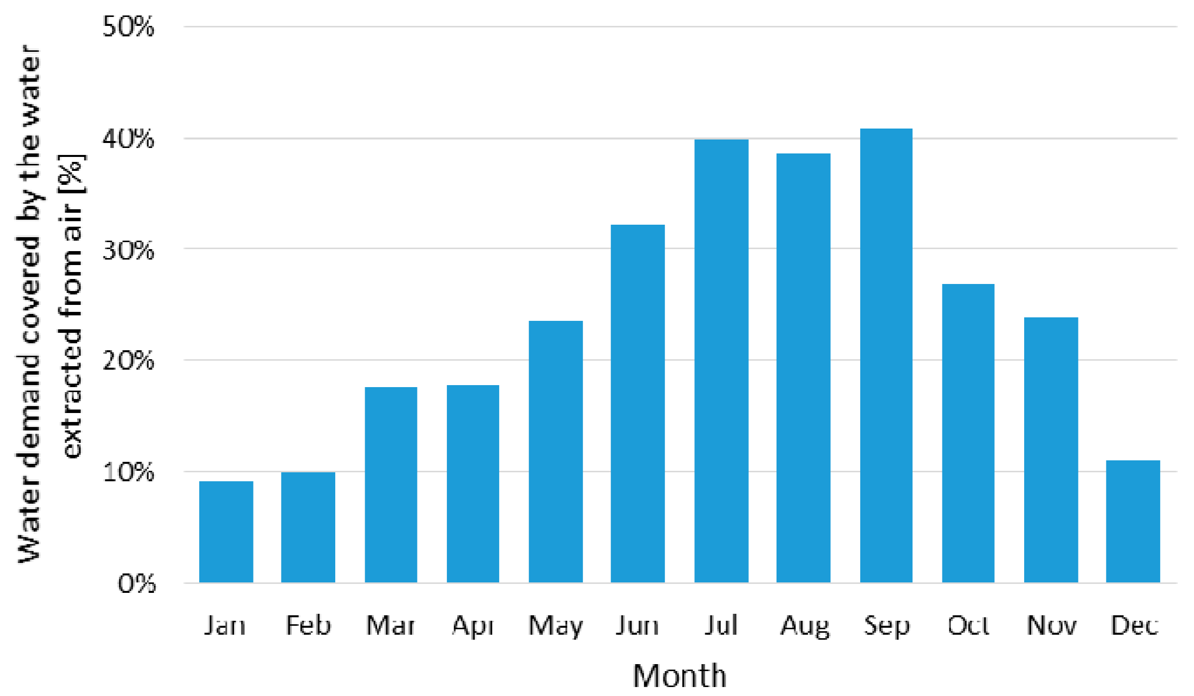
Taking into account the full occupation of the hotel for the whole year, the percentage of the entire water demand which can be supplied by the integrated system was calculated. In
Figure 15 results are shown for each month. During the whole year, it is possible to cover, on average, more than 24% of the water demand. From July to September, the integrated system can cover over 38% of nominal water needs. The water extracted can supply over 30% of the nominal needs, referring to the period during which the air conditioning system works at a full load (
Figure 15).
Taking into account design external conditions (35 °C and 60% of R.H.), the entire integrated system achieves water production of about 70.3 m3/day, which covers 47% of the nominal requirements. In this case, water savings due to the integrated system can decrease the average daily water consumption related to each guest to a value quite similar to the water amount assigned to each citizen. Effectively, with the contribution of the integrated system, the average guest’s daily demand is about 189 L per day, only about 8.6% more than the quantity considered for citizens in the Emirates.
It is interesting to highlight that a hotel smart water management can allow an average water demand reduction of about 30% [
16]. A combination between the integrated system and a wise water management can lead to an average water saving of more than 54% with peaks of about 70%. In that case, the water daily demand related to tourists is lower than the water share assigned to citizens.
Moreover, such an integrated system can be a proactive answer to the new green requirements that are taking place in the UAE rules and that should be considered in the future all over the world.
As for water costs comparison, an analysis based on local rules and energy supply costs compared with municipal water costs will be performed. Of course, it is not possible to make a general analysis that would be valid all over the world, because energy and water prices and local laws regarding water quality are very different from one country to another.
6. Conclusions
The integrated HVAC system calculated for a hotel, combined with water production, has been discussed in this preliminary investigation. The climatic conditions of the Arab Emirates coast were assumed for the analysis of the case-study. The HVAC system was designed for optimizing water production, and for using cooled air for hotel air conditioning needs.
The results show that this kind of HVAC system, in the considered climatic conditions, can produce a significant amount of water that can be used to cover a meaningful amount of the hotel water requirements. The next steps of the research will consider if the costs of the treatment of the condensed water to use it as drinking water can be considered affordable and if the production of water from the air can be competitive. A comparison between a traditional and an optimized system will be used for a deeper technical and financial analysis, to show the costs of drinking water and to evaluate how much the proposed solution may represent an effective sustainable means of reducing water consumption.


