1. Introduction
Road users driving in a tunnel devoid of a proper lighting system might be subject to a high situation of visual discomfort, in particular when the driver passes from the outside characterized by natural light to the inside of the tunnel, and vice versa. Such issue increases in the daytime, when outdoor illuminance (that is daylight) reaches its highest values. It is obvious that the planning of a lighting system for road tunnels expects the analysis of a series of peculiar problems. The system must be dimensioned and able to mitigate the problems provoked by the drop in the luminance level that affects the driver while passing from the outside to the inside of the tunnel. The visibility of an obstacle during this condition of transition depends on the sensitivity of the eye of the observer; the eye must adapt its performance to maintain the visual perception and this passage must be facilitated by the present lighting system. The sensitivity of the eye depends on the distribution of the luminance in the visual field. Each part of the retina has a sensitivity which depends on the present luminous flux and is affected by what happens in the other sections of the retina. If the luminance distribution varies, the eye must adjust to the new situation and it requires time (called adaptation period). Two different phenomena can occur: (i) the eye is able to perceive only those objects whose luminance is not lower than the one to which the eye is adjusted (i.e., before entering the tunnel, that appears as a dark area devoid of any detail); and (ii) if sudden changes in the luminance occur, the retina is not able to respond in a rapid way to the variation in the luminous stimulus and the observer can have visual problems for a few seconds. Both phenomena can occur separately or simultaneously and be characterized by other disturbing effects, as the phenomenon of the eyes reflection (that is the variation in the diameter of the pupil due to the change in the luminance of the visual field), reflection phenomena on the windshield of the car, atmospheric luminance phenomena. These issues were studied by Schreuder in 1964 [
1] who found a connection between the outdoor average luminance and the entrance luminance to give the possibility to the driver to identify a possible obstacle in a time interval that might allow him to slow down (it depends on the road travelling speed). These studies initiated the principles of the first regulations about this subject, suggested by the CIE in 1973, which have been updated until now [
2]. These regulations establish the idea of veiling luminance that takes into consideration the effects of the outdoor light in the atmosphere, the one provoked by the windshield and dashboard limiting the sight of the driver while approaching the tunnel. This veiling luminance becomes one of the main parameters of the regulations [
1,
2] for the planning of lighting on the initial section of road tunnels. Besides this parameter, other factors affecting the sight of the driver are: the age and her/his psychophysical condition and the current atmospheric conditions. The technical instructions of the CIE 88 [
2], in order to guarantee the driver (while entering a road tunnel) to identify an obstacle as soon as possible, the luminance required on the tunnel entrance threshold is defined. It depends on the outdoor luminance assessed as the average ponderal of the luminances characterizing a visual field delimited by a cone with a certain semi-opening angle, whose vertex is the observer and the axis the line joining the observer with the axis of the portal of the tunnel, which is placed at a distance that depends on the maximum driving speed allowed (Adrian method [
3]). The regulations provide the lengths of the different sections of the tunnel where the luminance can decrease according to the time interval during which the eye of the driver adjusts to the new lighting conditions. Concerning the uniformity of the luminance distribution inside the tunnel, the regulations are the same of those concerning the criteria of the road lighting: this can be guaranteed by a proper arrangement of the light sources and both the general value of the entire tunnel and the longitudinal value must be assessed. For a right lighting in tunnels, other phenomena that can disturb the sight of the driver must also be taken into consideration: (i) the “disability glare” (expressed in percentage) that cannot exceed the maximum limits set by the regulation; and (ii) the “flickering” that is the problem caused by the constant and quick appearance and disappearance of a light source in the visual field of the driver (that can be avoided by placing the lamps at a maximum distance which depends on the maximum driving speed allowed to the vehicle in the tunnel). Even choosing the features of the light sources affects the visual perception, in particular their chromatic performance which determines a light that favors the “visual acuity” of the details. The planning must take into consideration even the arrangement of the lighting devices (that affects the contrast of the objects lit), with a transversal emission with respect to the roadway, which is mostly symmetric and longitudinal with respect to the roadway that can have an asymmetric direction according to the direction of travel. All these factors are taken into consideration by the current regulations in order to have a proper planning of a lighting system that fulfills the demands and necessities of a road tunnel.
To avoid these potentially dangerous phenomena and ensure a safe driving environment, road tunnels must have lighting systems with high luminous fluxes at the tunnel entrance threshold zone and exit zones for sufficiently long sections which might allow the human eye to adapt to the different lighting conditions. In the interior zone of the tunnel which the regulation [
4] defines as “long”, it is important to control and limit the energy consumptions without forgetting the standards about the minimum level of illuminance required to guarantee safe conditions to the driver. Hence a high illuminance level is required both at the beginning of the tunnel (to avoid the “black hole” effect) and the end (to avoid the “white hole” effect), in this way the eye will have the time to adapt since the luminance decreases from the tunnel entrance threshold of the tunnel reaching its lowest levels in the interior section [
5,
6], and then increases again with the approaching of the exit zone.
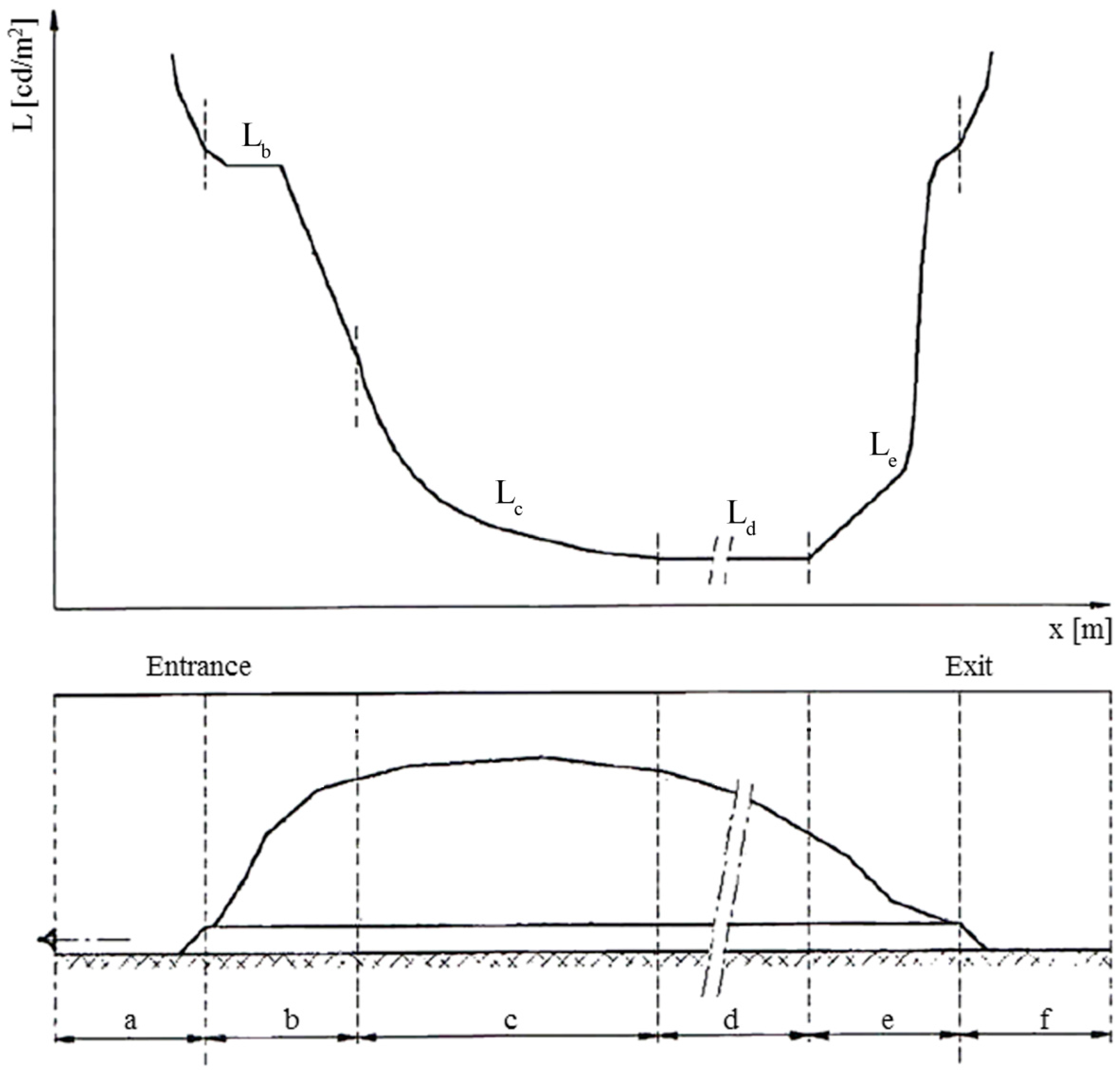
The current regulation [
5,
6,
7,
8] sets the luminance level (expressed in cd/m
2) on the roadway defining the zones in the tunnel and their different illuminance levels (a: access zone; b: threshold zone; c: transition zone; d: interior zone; e: exit zone; and f: exterior zone), as shown in
Figure 1.
Road tunnel lighting systems must be planned to work at their best even in the worst conditions possible that might happen while functioning, and be ready to face any kind of outdoor natural illumination with respect to both the morphological conditions characterizing the entrance of the tunnel and outside climatic conditions.
A system thus dimensioned presents higher performances than necessary, since the level of solar radiation in the outdoor environment is lower than the maximum values expected. Recently, strategies to decrease energy demands of lighting in tunnels are currently under investigation, for example, the forestation of the surroundings of tunnels gates with specific vegetal species having low reflectance [
9], using pergolas or tension structures [
10,
11] or introducing sunlight inside the tunnel with light-pipes or similar technology [
12,
13].
In these conditions, the flux emitted by artificial light sources in the tunnel entrance threshold, transition and exit zones must be partialized through the exertion of dimmable light sources and a control system able to adapt the powers absorbed according to the levels of illumination required which in turn depend on the outdoor environmental conditions. This is possible by equipping the system with artificial sources that can be partialized [
14,
15,
16].
LED sources [
14], besides being highly efficient, are optimal electronic control systems thanks to their features; however it is necessary to use a negative feedback control system (which is usually characterized by high equipment and installation costs) with a certain number of sensors providing useful information to the control system for the regulation of the flux emitted by artificial sources. This leads to the system to be less reliable with a high level of maintenance. The maintenance of a road tunnel presents some difficulties which, in order to be performed in a safe environment, might lead to slow the vehicular traffic. This determines higher operating costs.
In the negative feedback lighting system, a control system analyzes the values of luminance measured by sensors located in the threshold, transition and exit zones and adapt the flux emitted by artificial sources. However, regulations [
7] must be taken into account and the luminance L
t in the transition zone is calculated according to Equation (1):
where L
e is the luminance at the threshold zone; Xv is the distance [m] in the tunnel measured from the beginning of the transition zone, v is the reference velocity [km/h].
To reduce the costs of the control system and increase its reliability, an alternative to the negative feedback control system can be a pre-programmed control unit which thanks to a schedule based on simulations performed through light planning prediction softwares dims the lamps to limit wastes adapting the power required by the system to the conditions expected for the entire year [
17]. These simulations, which were performed assuming clear sky conditions, can provide accurate information concerning the reinforcing flux that must occurs in the zones of the tunnel. The only control which must be present is a twilight switch located in the tunnel entrance threshold and exit zones of the tunnel, to reveal whether outside there is an overcast sky or not.
The predictive control system [
18,
19,
20,
21,
22,
23,
24,
25,
26] here suggested has a three-level structure (
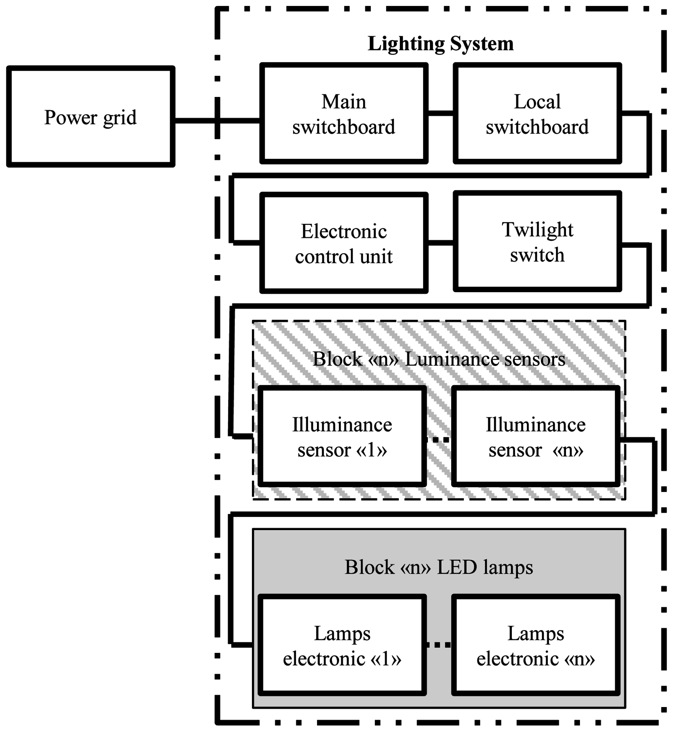
Figure 2): an upper layer with a control system (consisting of a pre-programmed software used according to predictive simulations performed thanks to software able to simulate the interaction between natural daylight with artificial sources and their illuminations levels); a middle layer where the control unit, with respect to the input provided by the twilight switch, regulates the dimming of the light sources; and, the third layer, which is the actual control, where the electronic on-board permits to regulate lighting sources to provide a proper illumination.
Among the reliability parameters characterizing the system, the Mean Time Between Failure (MTBF) is deeply affected by the components of the reliability chain (
Figure 3), with lower MTBF values than the one of the other components [
27,
28]. The sensors of the system are the weak point: if properly substituted (in this case thanks to the pre-programmed control unit) it is possible to obtain some benefits from the reliability of the system. Hence, a technological system with higher MTBF values, able to guarantee a proper functioning, is a system with lower extraordinary maintenance costs [
29]. Exerting this type of system means to obtain energy and maintenance costs savings. However, the higher expenses determined by the equipment and installation of LED sources is compensated by savings obtained through the exclusion of the sensors.
Figure 3 shows the reliability chain of the components characterizing the system. Concerning the assessment of the reliability parameters [
16] this study will not take into consideration the block of the lower layer (
Figure 2) that is the block related to the illumination of the lamps, focusing instead on the components useful to the system regulation. The block concerning the luminance sensors (white and grey fields in the figure) if excluded, due to the substitution by the pre-programmed logic system, leads to an improvement in the MTBF (
Table 1) with an increase of the 260% of its value. This determines significant and positive changes for what concerns the maintenance of the system. For the method of calculating, the reader can see References [
16,
27,
28,
29].
2. Case Study
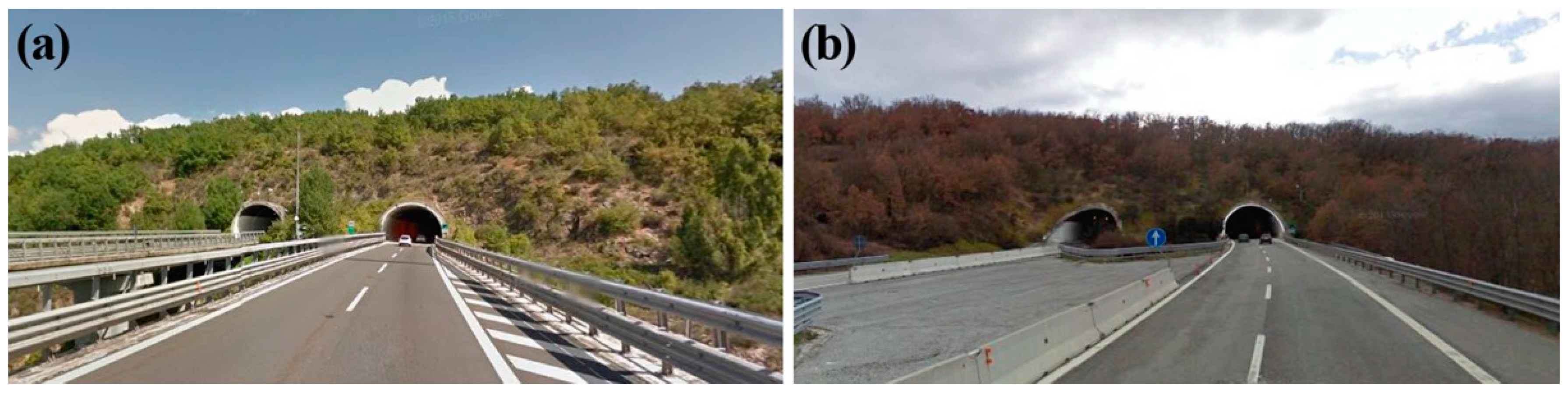
To examine in an accurate way the advantages of the system in the road tunnel here suggested, with respect to the parameters required by the current regulation about lighting, the case study took into consideration a road tunnel located in Central Italy on the A24 (Rome-l’Aquila) crossing the middle of the Apennines. The terrestrial coordinates are: 42°20′38.45′′N (latitude) 13°19′06.74′′E (longitude). This tunnel is double-arched, without slope and about 1500 m long with a vehicular traffic flow within the average and a maximum speed limit of 130 km/h.
Figure 4 reports the entrances of the tunnel in both directions.
Lighting systems must be properly dimensioned (to face the visual demand of a driver which is affected by the visual perception of the human eye, hence it must comply with the current regulation) since they must be able to face the worst conditions possible the drivers might encounter (as required by the regulation) while entering and exiting the tunnel with respect to outdoor daylight conditions which can result the most difficult for the sight of the driver. This aspect is very important, together with the problems concerning economic issues about energy maintenance and management. The main objective is to find an optimized solution that makes the system as less energy-consuming as possible with low maintenance expenses. In this article, where the first step was the examination of Case 1 with the tunnel presenting a traditional lighting system characterized by symmetric lighting sources in accordance with the current regulation (allowing U-turns in case of emergency or maintenance), formed by high-pressure sodium artificial light sources only (HPS), the effects on the energy consumption with respect to LED sources (Case 2) were examined. Once the annual energy consumptions of this type of system were assessed, the lighting system was optimized through a pre-programmed logic control system (Case 3) which over the year regulates the flux emitted by the lamps in the daytime to make the different levels of luminance (about the threshold and exit zones of the tunnel) adequate to outdoor daylight conditions.
Table 2 reports briefly the scenarios examined. The decision was to turn off HPS lamps. Where this was not possible, some HPS lamps together with LED lamps were partialized according to the requirements (while taking into consideration the costs, the attempt was to limit as much as possible the dimming of HPS lamps; on the other hand, LED lamps present an electronic on-board allowing their regulation).
The regulation [
2,
4,
5,
6,
7,
8], with respect to atmospheric luminance and the section in the sky functioning as a background to the driver while crossing the entrance of the tunnel, allows the assessment of the minimum luminance value required in the threshold zone while taking into consideration: maximum speed limit, the type of installed lighting system and the different luminance levels of the dashboard and windshield of the vehicle. In this study (in reference to
Figure 1), during the most adverse conditions of the year, the minimum luminance assumed in the project in the threshold zone must be L
b = 148 cd/m
2 (for about 165 m); it must diminish in a progressive way in the transition zone (for about 515 m) until L
d = 3 cd/m
2 in the interior zone (for about 675 m), and then increase again up to L
e = 15 cd/m
2 in the exit zone (for about 145 m).
Table 3 reports briefly the characteristics of the luminous sources used in this case study.
The market does not have yet LED sources able to guarantee luminous fluxes so intense to substitute HPS lamps, which have a higher power. This is why the suggestion is to realize a mixed solution with LED + HPS, where LED lamps can be exerted in all those zones requiring a lower level of luminance without exceeding the number of devices used to avoid problems that might arise with their installation. In the emergency sections, in order to guarantee the high fluxes required during the most demanding periods of the year in accordance with the standards set by the regulation, LED and HPS lamps were used, and when the power required was not the entire amount at disposal the choice was to use LED lamps which were dimmed thanks to their on-board electronic, thus dimming the smallest number possible of the 470.6 W HPS and turning off one or both HPS sources present in the 880 W devices.
3. Lighting Simulations
Thanks to the prediction software DIALux Evo [
30], it was possible to simulate the lighting system to perform its dimensioning in accordance with the standards set by the regulation with respect to the most demanding possible conditions while operating and evaluate how its lighting performances vary with the power variation of each artificial source according to the different outdoor natural lighting condition. The longitudinal luminance values were monitored in the entire tunnel on calculation surfaces located at regular intervals (an equal distance of 20 m) in the center of the highway. To obtain a uniform illumination on the whole highway, a ratio between the minimum illumination and the average illumination higher than 0.7 in the orthogonal road sections with respect to the direction in which the vehicles were driving was set.
The first step for the dimensioning of the tunnel lighting system [
31,
32] was to examine the most demanding conditions caused by outdoor daylight in the summer solstice with the highest solar radiation (12.00 p.m. with respect to the solar time). Concerning Case 1 and Case 2 (
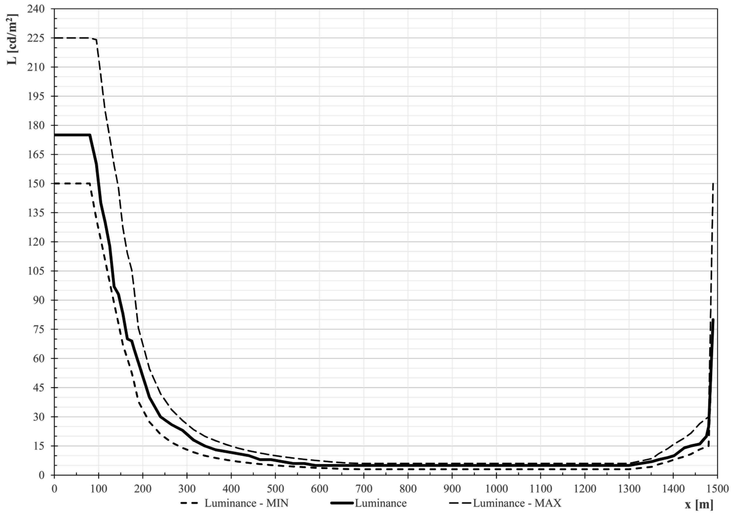
Table 2), in order to be able to compare the performance of both planned systems (HPS vs. HPS + LED), they were dimensioned to obtain the same lighting results when the maximum luminous flux was required. To observe the regulation, the luminance obtained by the system for the entire highway must report values within the limit curves: superior to the minimum luminance curve, whose values depend on the outdoor conditions characterizing the access zone of the tunnel and inferior to a maximum luminance whose values are a function of the minimum luminance curve. The solutions fulfilling these standards observe the regulation [
2,
4,
5,
6,
7,
8].
Figure 5 reports the trend of the different luminances of the highway according to a certain day as in the conditions assumed in the project.
In order to have these results both systems, Case 1 and Case 2, were dimensioned by using the artificial sources reported in
Table 3.
Table 4 reports the number of lamps for each type of device and the power installed.
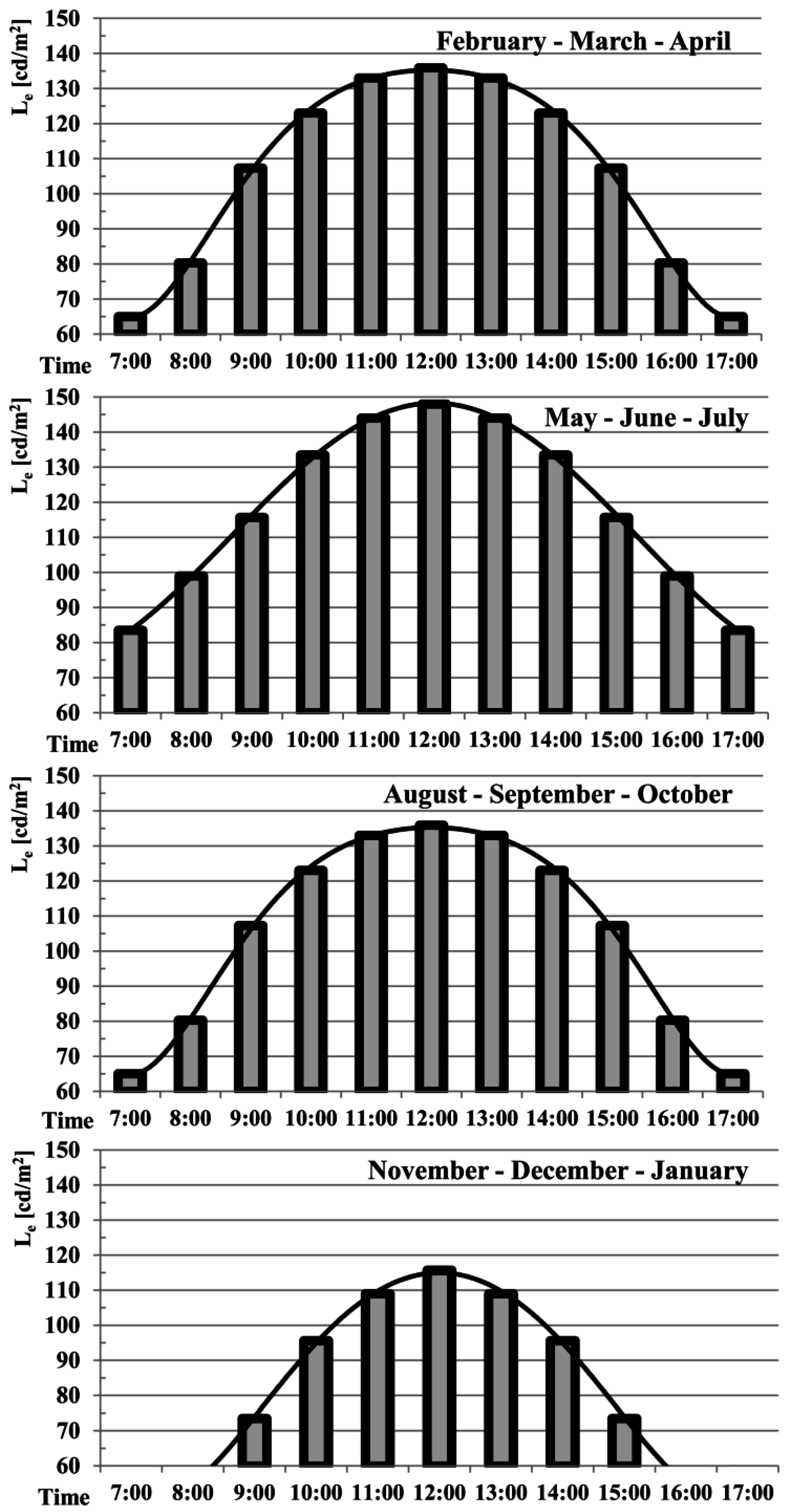
To study the conditions regulating (turn off or dimming) the sources of the system (using the same lamps of Case 2), the next step was to analyze outdoor lighting conditions in the presence of solar radiation (the sky was assumed to be clear) according to a certain hour in the daytime and the season. The outer luminance, important for the consumption inside the tunnel, is the luminance in a cone of 20° seen from the safety distance.
Figure 6 reports the luminance values in the access zone of the gallery. To perform the simulations, the days taken into consideration represented an entire season: the summer solstice for the entire months of May, June and July (MJJ) with a total of 92 days, the autumnal equinox for the entire months of August, September and October (ASO) with a total of 92 days, the winter solstice for the entire months of November, December and January (NDJ) with a total of 92 days, the vernal equinox for February, March and April (FMA) with a total of 89 days. In this first approach study, the simplifying assumption of a clear sky with no cloud cover was made.
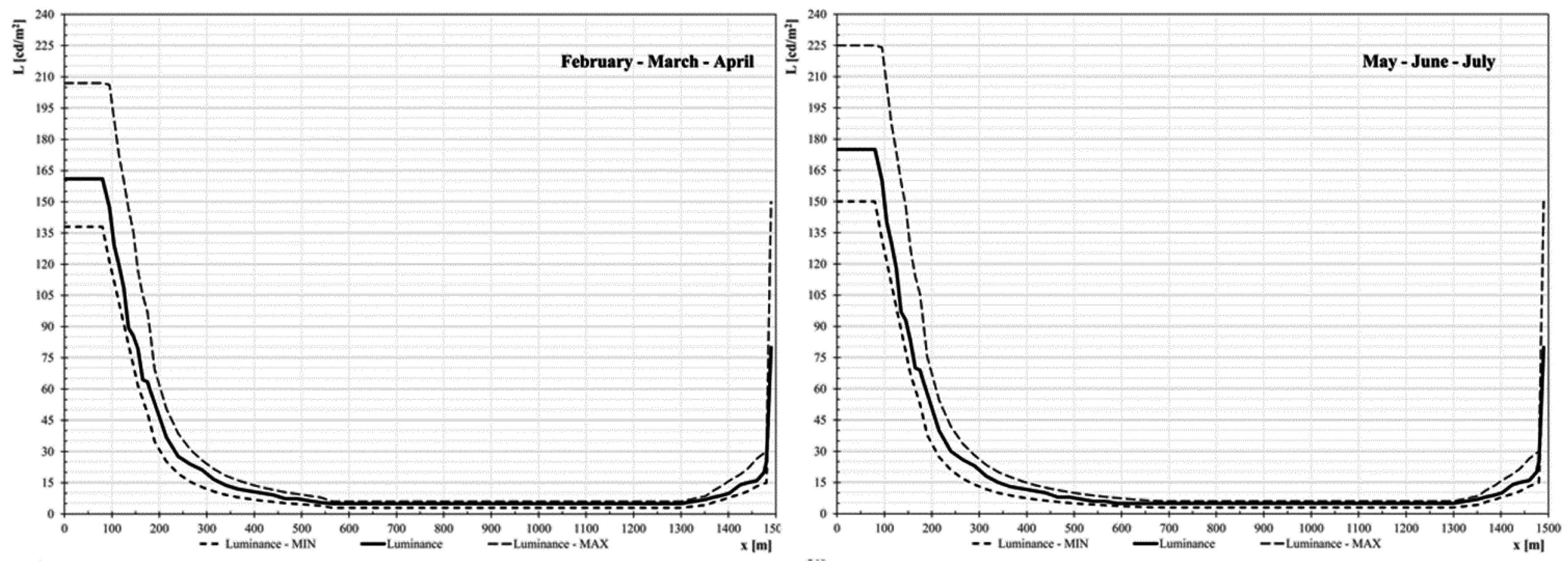
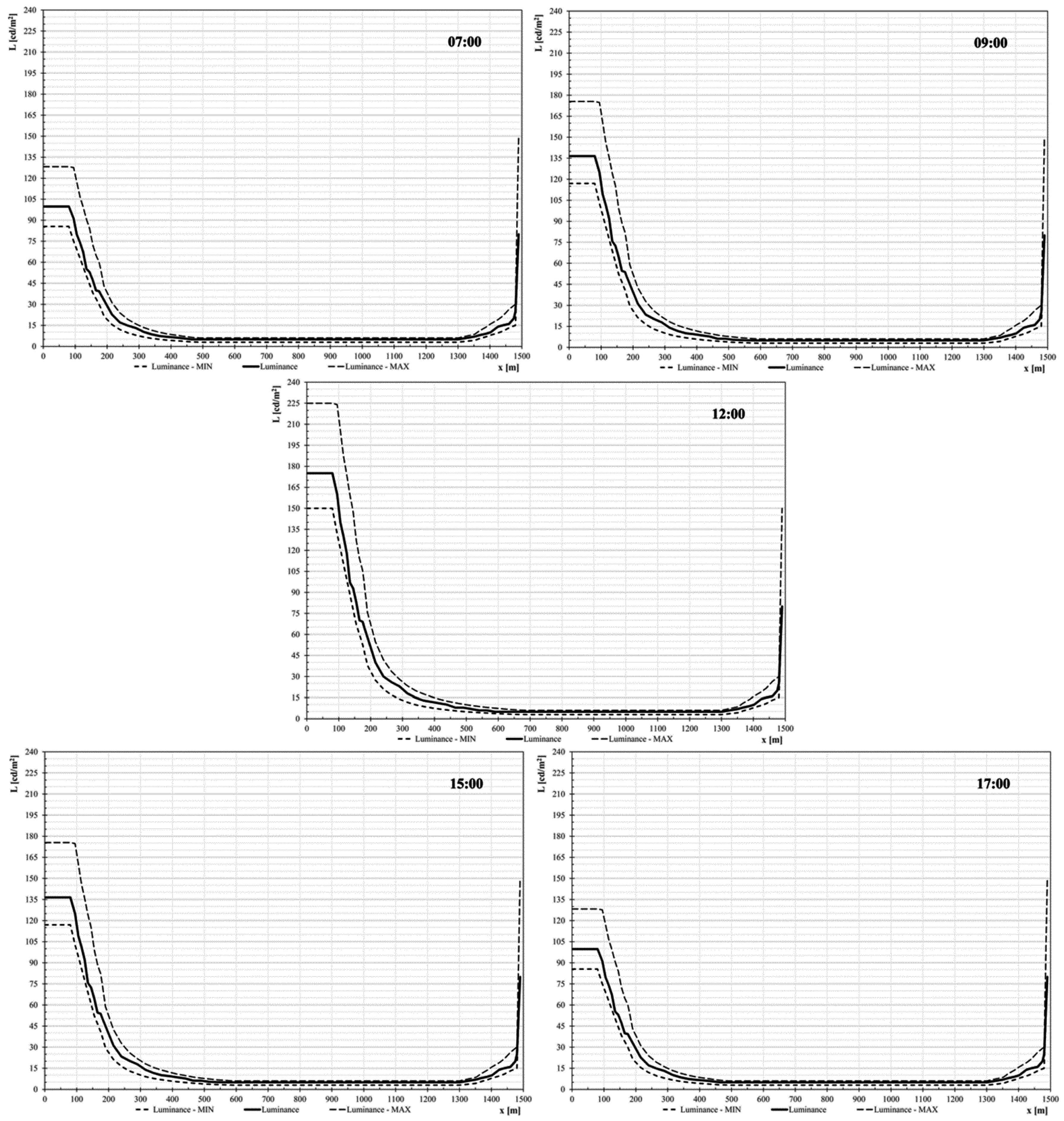
The data obtained allowed performing the simulations by dimming the system (Case 2) to determine the power used with the changing of the lighting performances of the artificial sources observing the different demands according to outdoor natural illumination. In this way, the tunnel luminance values changing during the day (
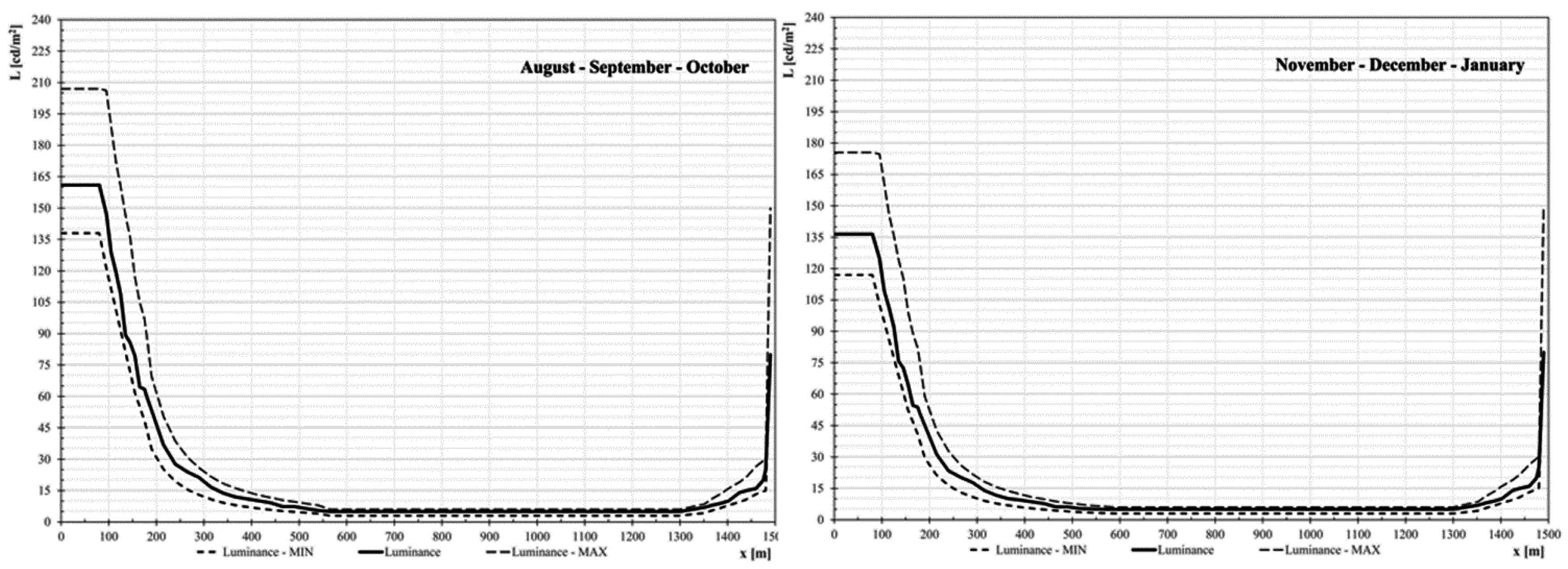
Figure 7 reports the most demanding day of the year, the summer solstice) and the year (
Figure 8 reports the most demanding hour of the day).
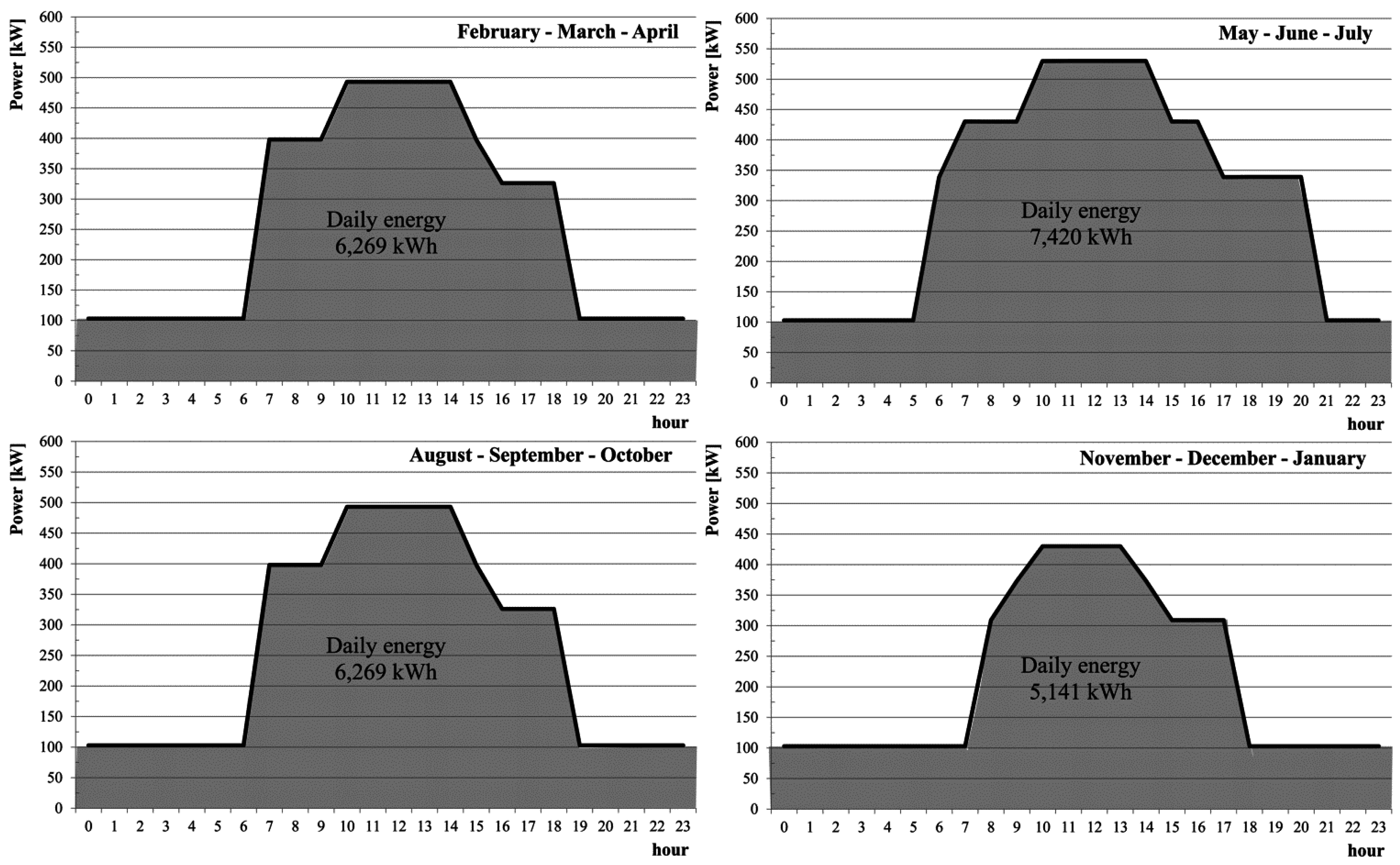
Thanks to the simulations performed, it was possible to make an evaluation of the different amount of power exerted over the course of time (concerning Case 3, the dimming values that must be applied to each luminous source are known), with respect to the changing of outdoor lighting conditions.
Figure 9 reports the hourly trends of the total power exerted according to the different seasons of the year.
4. Maintenance and Energy Saving
The powers installed in the three Cases are reported briefly in
Table 4 and
Figure 9. It is possible to determine the annual power required by each configuration (
Table 5).
The daily consumptions reported in Case 2 are equal to those of Case 3 with respect to the period of the year characterized by the most demanding conditions for the system to operate (MJJ). The overall of the annual consumptions reports that the most energy-consuming system is Case 1, whereas the most energy-saving system is Case 3.
The MTBF used for the reliability analysis of the systems examined is positively affected by the exertion of LED lamps (Case 2), substituting partially HPS lamps (Case 1), since LED lights service life is longer than HPS lamps’ (
Table 3) [
33]. The maintenance of the system of Case 2 reports lower costs than Case 1. The benefits, energetically speaking, caused by the dimming process (Case 3) are obtained without exerting luminance sensors or causing problems to the MTBF of the whole system due to presence of the sensors in the reliability chain.
Obtaining an energy optimization of a system, which represents a disadvantage to its reliability, can determine extra costs for the maintenance, which, economically speaking, can nullify the benefits obtained through energy savings. In order to examine the financial scenarios of the three Cases, the EcoCalc software [
34], provided with the data reported in
Table 6 [
35], was used.
The costs of the electronic devices necessary for the partialization of the luminous fluxes in Case 3 are estimated to be of €129,000.00.
Table 7 shows the results of the economic analysis.
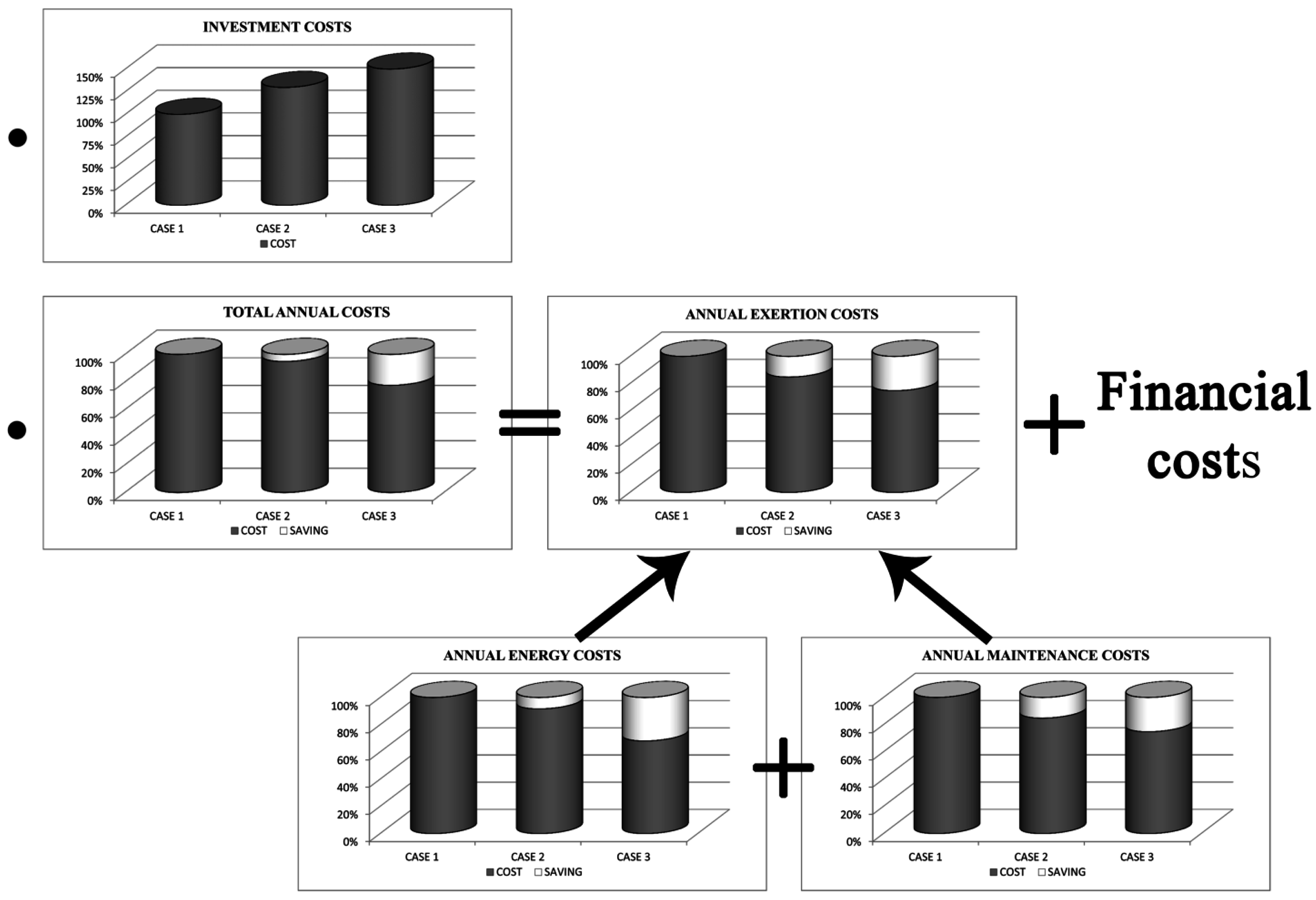
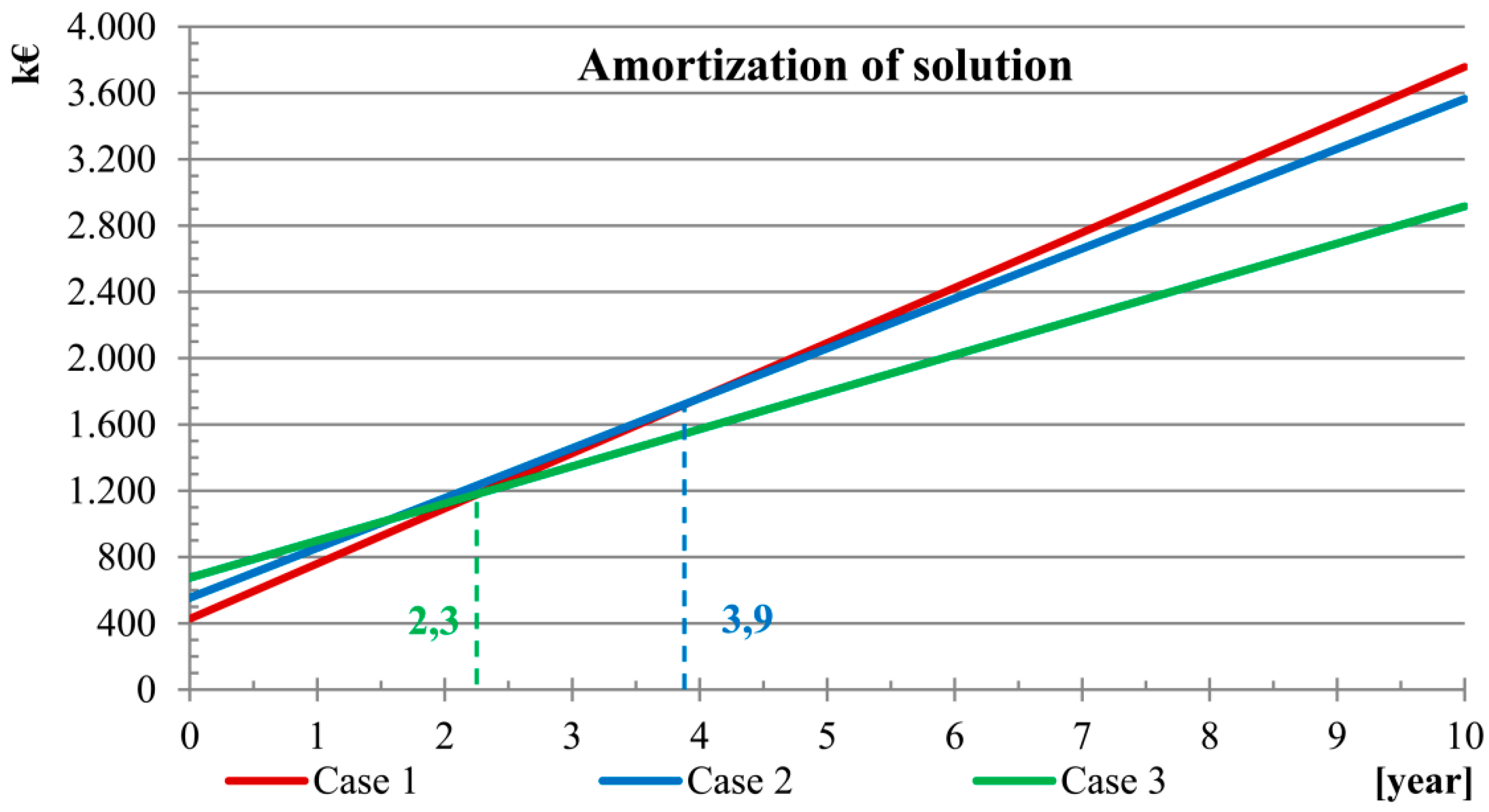
Cases 2 and 3 report higher installation costs than Case 1 and they can be considered valid if they are amortized in a reasonable time interval thanks to the savings obtained during the operating time.
Figure 10 shows the amount of time required to have a return on investment.
Figure 11 reports the comparison between Case 1 (that is the most expensive solution during the service life of the system) and the other Cases with respect to the best technical solutions adopted by the lighting system; it reports briefly the percentages of installation and exertion costs of the systems.
5. Conclusions
Over the last years, the number of studies related to energy issues has been progressively increasing. However, energy demand not plays a key role only in building energy performance [
36,
37], it is also represents in road tunnels a significant weight, economically speaking, on road networks. The current regulation [
1,
2,
3,
4,
5,
6] requires luminance levels able to guarantee a visual comfort for the drivers because they must not encounter situations that might alter their visual perception while crossing the threshold zone of the tunnel [
38]. The sections that must be provided with emergency lighting that is adequate with respect to outdoor solar illumination also depends on the maximum driving speed allowed and require high levels of luminous fluxes. The power installed and the amount of energy consumed by the lighting systems during the entire year need to be optimized, though energy costs reduction must not damage the reliability of the system.
Higher maintenance costs can nullify the energy saved [
39,
40] and the outages caused by the increase in the maintenance become unjustified. In order to carry out an optimization that takes into consideration both these demands, the case study examined was a road tunnel (whose length was defined by the regulation as “long”) crossing the Appenines in Central Italy. Different system scenarios were simulated: (i) Case 1: traditional system formed by HPS lamps; (ii) Case 2: system formed by HPS and LED lamps (with a higher level of reliability and energy efficiency); and (iii) Case 3: system formed by the same sources of Case 2 equipped with a luminous fluxes control system regulating each luminous source, which varies according to the outdoor solar radiation changing over the course of the year (that is during the days and seasons). A negative feedback control system (depending on the data acquisition of outdoor luminance values and the emergency areas presenting artificial illumination) requires several luminance sensors, which, if their MTBF values are taken into consideration, will weaken the reliability chain of the system components. This leads to higher maintenance cost. In order to avoid such problem, it is possible to perform a partialization of the system thanks to a pre-programmed electronic control unit, which, according to a schedule, regulates the flux emitted by the luminous sources [
41]. Concerning the data useful for its scheduling, one solution is to focus on the results provided by the lighting simulations performed through the prediction software (DIALux) [
30]. It is possible to simulate outdoor lighting conditions (in the daytime) and adjust how the system responds to the changing of the solar radiation. Simulations cannot take into consideration random meteorological events (e.g., an overcast sky). A very simple solution can be the exertion of just one twilight switch located outside the tunnel to avoid the regulation and in case of hostile weather provide the maximum power to the system.
While examining the simulations carried out during an entire year, it was possible in the three Cases examined to perform a dimensioning of the tunnel lighting system in accordance with the regulation, calculating installation costs together with energy and maintenance demands. The results provided by the software EcoCalc [
34] show that Case 3 has a system whose installation costs are 58% higher than Case 1 (which is the most convenient economically speaking), while Case 2 costs are 29.8% higher than Case 1. However, higher installation costs of Cases 2 and 3 will be paid back over the course of time through lower annual overall costs of 22.47 and 5.1%, respectively, with respect to Case 1. This is possible thanks to significant savings in percentage both concerning energy and maintenance (
Figure 11). Whereas the higher installation cost (without the costs related to electric power cable [
42,
43]) of Case 2 will be amortized after 3.9 years with respect to Case 1, for Case 3, such time interval decreases to 2.3 years. This is a benefit for the environment as well: given that the specific CO
2 emission rate in Italy is 0.402 kgCO
2/kWh [
44], there is a reduction of the CO
2 emitted of the 8.35% and 31.90%, respectively, for Case 2 and Case 3 with respect to Case 1.
The simplifying assumption of clear sky is precautionary for what concerns the annual saving of the electrical energy reported in the paper. Even though with reference to this assumption, the financial results obtained show a saving that should not be ignored while applying the system suggested. In a real situation, where this hypothesis is not always satisfied, the suggested system presents a twilight switch that in case of low outdoor lighting level during the day (winter day with a cloudy sky) controls the system by releasing lower values of light fluxes (these cases, with transitory random periods, will be examined deeply in future studies) hence requiring a lower amount of electrical energy.


