1. Introduction
Construction is an important industry for many countries economy as it contributes mostly to their GDP. Prefabrication is an “umbrella” term and it covers a range of different systems and processes. These will include structural, architectural and services elements. It was also mentioned to as offsite construction or modular construction where building components are manufactured and assembled in a plant instead of the construction site before the final building. Prefab can be categorized into components, panels (2D), modules (3D), hybrids, and unitized whole buildings [
1]. It is recognized by both design and construction professionals as one of the most common methods where the benefits include its facilitation towards achieving high quality construction, reducing health and safety risks, improving in planning, control, and innovation environments, as well as, facilitating organizations to be more successful preventing injuries particularly related to hazards of sustainable elements such as “construction at height, overhead, with energized electrical systems, and in confined spaces” [
2,
3].
Prefabrication is regarded as the most efficient way to achieve building industrialization and green buildings in China. This is due to its socio-economic and environmental benefits, including a large saving of construction time, better quality control and engineering performance, less construction and demolition waste, and less pollution [
4,
5,
6]. This construction method has been widely adopted in China’s building industry. The design of beam–column joints is the most complex and critical in the whole prefabricated building system. The joint is usually the most fragile member of the whole structural system and the failure of joints often leads to the failure of the whole structure. The connection mode of beam–column joints is therefore key to the whole prefabricated structural system. Dry-type connection joints are the latest development [
7,
8,
9,
10].
There has been a plethora of research on prefabricated concrete member joints for industrialized buildings. Huang [
11] compared the advantages and disadvantages of dry connections, and improved various dry-type connection joints, providing a basis for future related research. Yan [
12] conducted the reversed cyclic loading test on two precast prestressed concrete beam–column joints that were fabricated with two different concrete strengths in the keyway area. Ousalem [
13] conducted the low-cycle repeated loading tests on precast high-strength concrete structures. Precast beams were spliced and connected by bolts in the span. The results showed that a plastic hinge would form at the beam end under the action of low-cycle repeated loading, while the stiffness, strength, and other properties at the bolt joint were better, and no plastic hinge was formed. Cheng [
14] designed the middle joints of prefabricated partial steel-reinforced concrete frame beams and columns and tested the failure patterns and hysteretic curves under the action of low-cycle repeated loading. Choi [
15] studied the new type of assembled ductile joint by repeated loading tests. Nzabonimpa [
16] proposed the dry-type mechanical beam–column connection joint for fully-restrained bending moment connection of concrete components. Through tests, analysis, and research, the structural performance of the dry-type connection joint was verified, and the parameters affecting the performance of the dry-type mechanical bending moment concrete joint were determined. Other scholars have also further studied dry-type connection joints [
17,
18,
19,
20,
21].
Based on a review of the literature related to prefabricated beam–column joints, this paper aims to: (1) propose a feasible prefabricated concrete frame structure system with energy-dissipating members, (2) design a new dry-type high-strength bolted joint, and (3) study the joint’s failure mode and mechanical performance by means of a pseudo-static experiment. The experiment provides a basis for analyzing the performance of the new joint by comparison with several other dry-type connection joints. The research results not only provide experimental basis for the further prefabrication applications in particular but also contribute to construction’s sustainability in general.
2. New Dry-Type Connection Joint
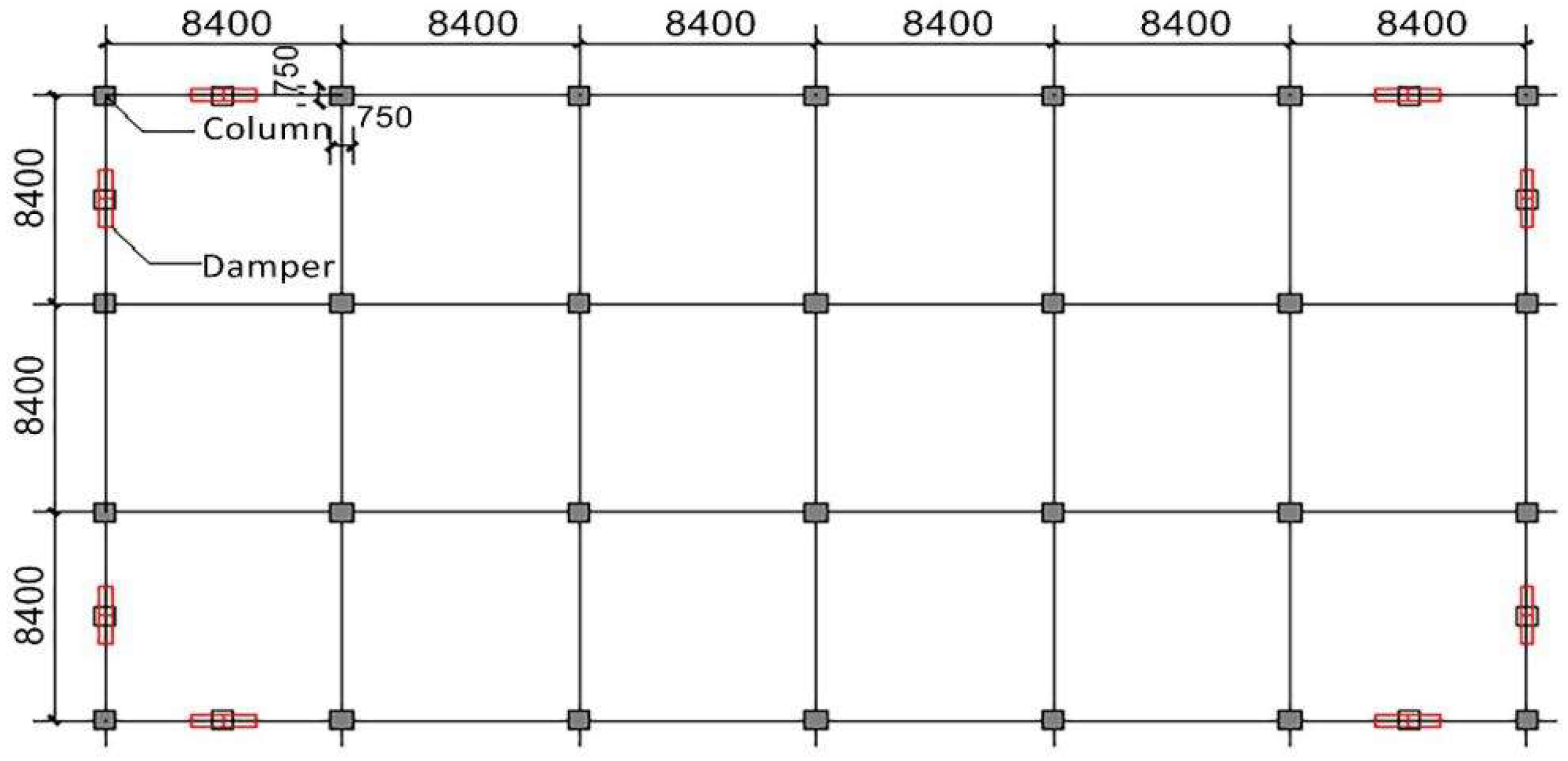
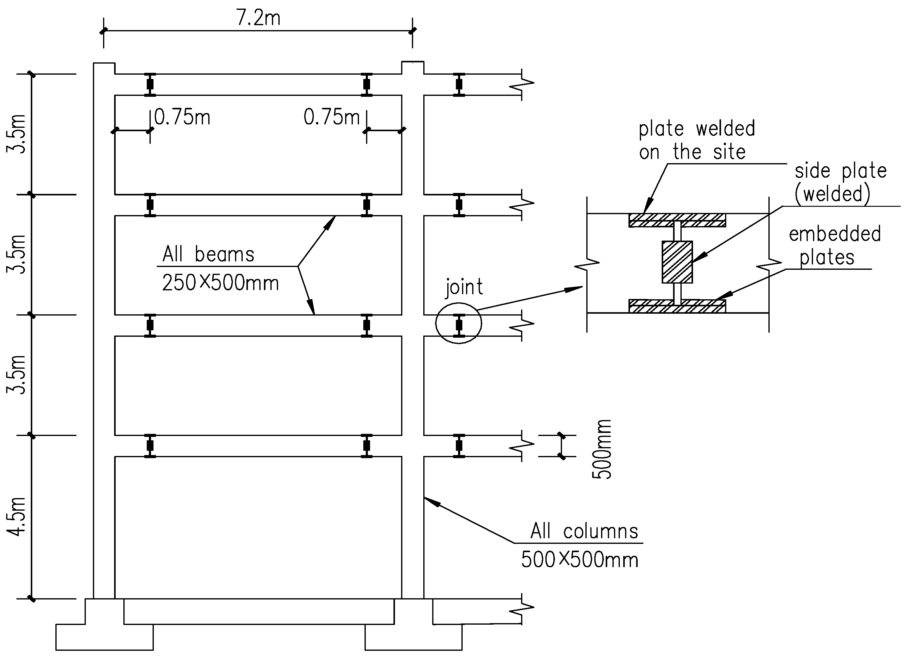
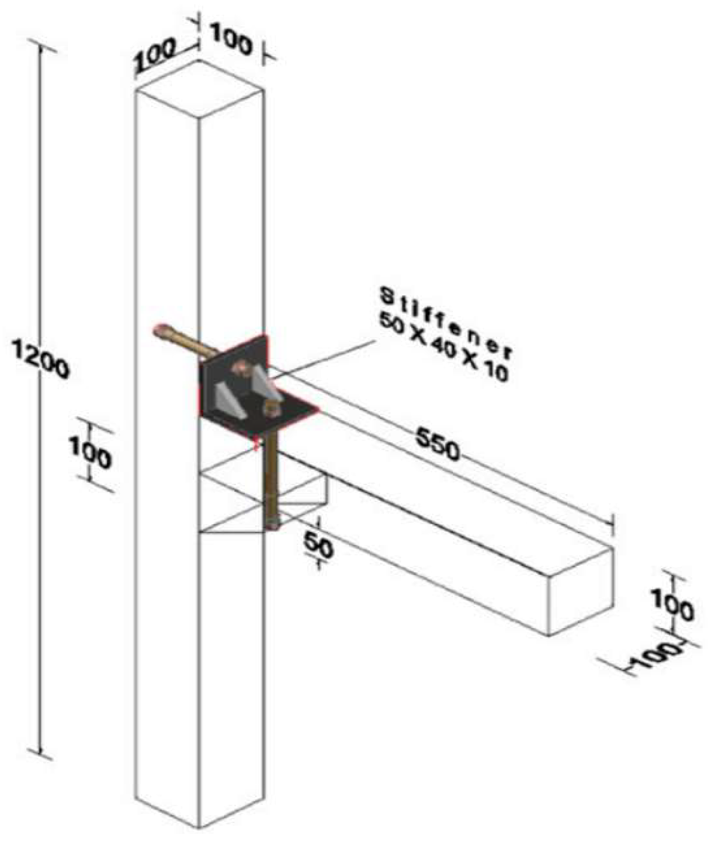
Considering that the new joint connection method is used in conjunction with the energy-consuming component, the joint is required to have a large deformation. Therefore, the test components for this study are taken from the assembled 3 × 6 frame structure, without secondary beams, and with a standard column span of 8.4 m and floor height of 4.2 m (see
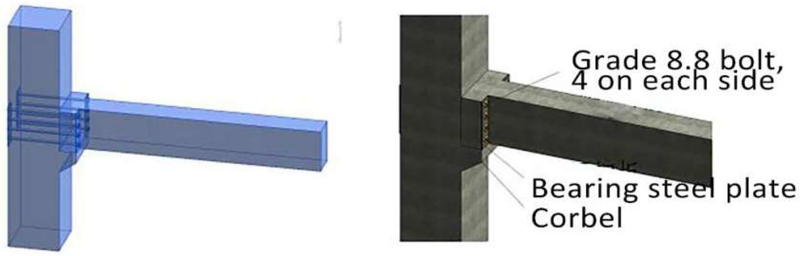
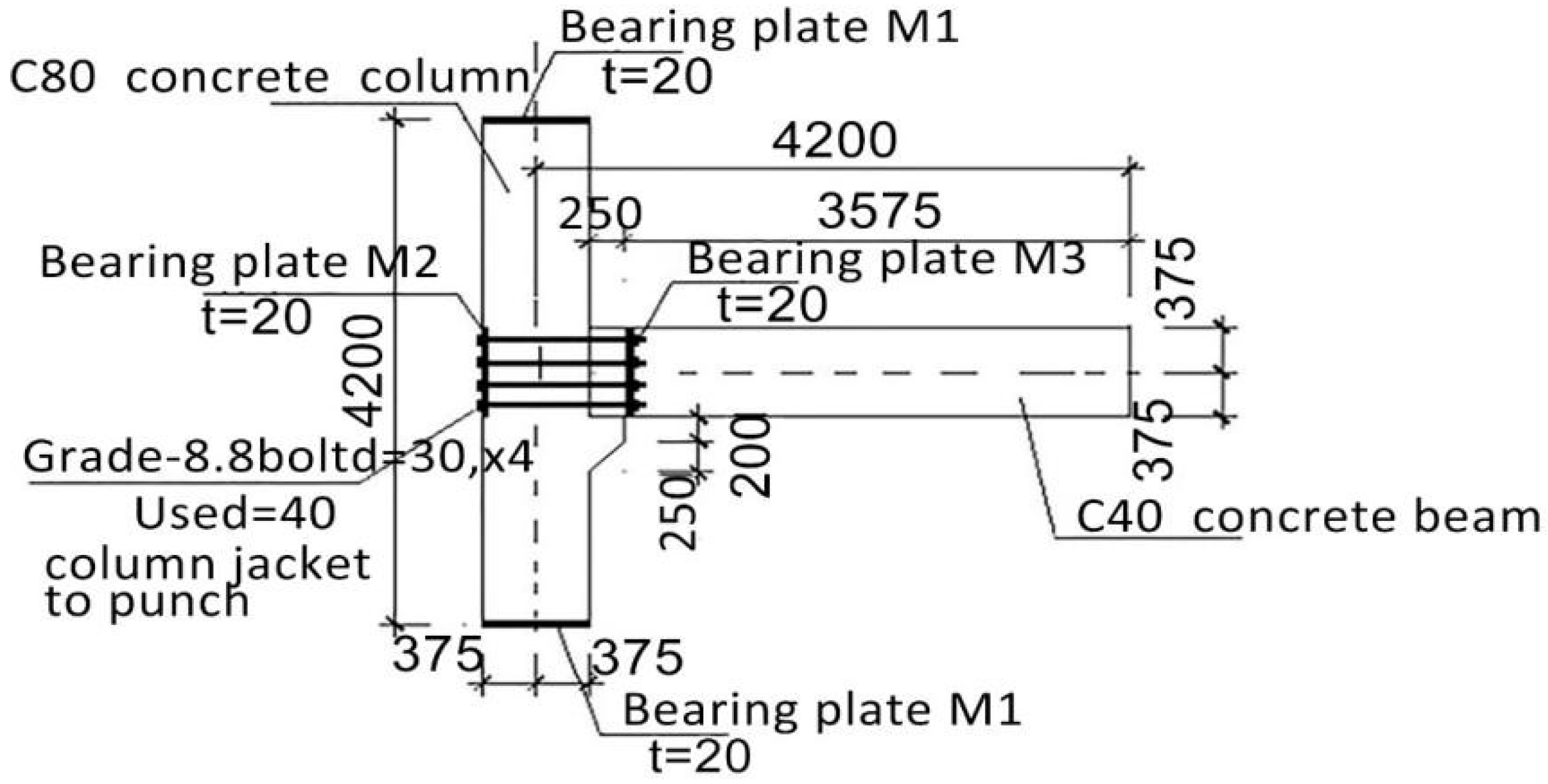
Figure 1). The concrete grade of the 750 mm × 750 mm column is C80, the concrete grade of the 400 mm × 750 mm beam is C40, and the rebar grade is HRB400. Eight grade 8.8 high-strength bolts with a diameter of 30 mm are used as semi-rigid joints for connection (see
Figure 2 and
Figure 3), with the joint stiffness coefficient of 0.5 and a theoretical ultimate bending moment of 456 kN·m/m.
The strength grade of concrete of column and beam are C80 and C40 respectively. The strength grade of stirrup of beam and column are both HPB300 when the strength grade of longitudinal reinforcement is HRB400. The strength grade of bolt is 8.8. Before the experiments, tests of material properties for concrete, steel bars, and bolt are conducted at materials mechanics laboratory. Each batch of concrete is reserved with 9 test blocks with a size of 150 mm × 150 mm × 150 mm. 3 days, 7 days, and 28 days of on-site maintenance are carried out, respectively. Compressive tests were carried out in accordance with the standard of mechanical properties test method of ordinary concrete (GB/T50081-2002). The measured compressive strength results of concrete cubes are shown in
Table 1.
Three samples were selected from each batch of reinforcement bars and bolts for tensile test. The measured yield strength, tensile strength, and elongation of reinforcement bars and bolts are shown in
Table 2.
3. Tests Process
3.1. Specimen
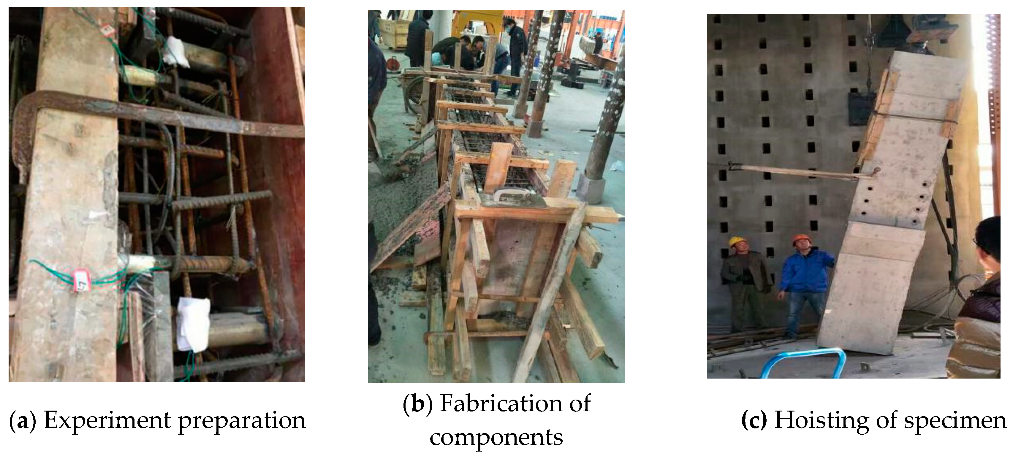
The production of prefabricated beams and columns was completed in the Building Structure and Underground Engineering Laboratory. The production and installation procedures of the specimens were as follows (see
Figure 4).
Step 1: Experimental preparation
The first step was to prepare wooden formwork of good texture, hardness, and no distortion, and soak it with water. The necessary reinforcement material was then positioned in accordance with the construction drawings. High-strength bolts were then located on the surface of the beam and column, and strain measurement gauges attached to the reinforcement bars for experimental purposes. In the latter process, the part of the bar where the gauge was to be fixed was ground smooth with a grinder and the surface cleaned with anhydrous alcohol. Cyanoacrylate 502 instant aadhesive was applied to the polished part of the strain gauge and it was wrapped with rubber and waterproof tape. The outside was covered with cotton cloth over which epoxy resin was evenly applied and then fastened with a plastic strip. Finally, the strain gauges were numbered and labelled after being wired. The gauges were checked at the same hour of the day on daily base to see if the wire was still energized in case there had been a short circuit that would impede the smooth progress of the test. The layout of strain measurement gauges is described in the following section.
Step 2: Fabrication of components
In this step, the binding of the steel bar of the beam and column is completed. The core stress area of the beam and column joint is reinforced and the reinforcement is inspected according to the final version of the construction drawings. Bolts should correspond to the holes in the steel plate joint and the beam-column joint. Concrete is mixed in the factory, transported to the laboratory, poured into the supported wetted formwork, and cured in the laboratory. Water is sprayed over the concrete three times a day for the first four days to improve the strength of the concrete for later natural curing. The formwork is removed after the component has been fully formed.
Step 3: Hoisting of specimen
Two lifting rings are welded at the diagonal position of the top of the column to facilitate the lifting of the column. Thick steel wire rope is used in the process of lifting, and wooden formwork is placed on the contact position between the concrete surface and the steel wire rope to prevent the concrete from being crushed, and then it is hoisted flat to the test bed. The joints of the beam and column are tied together for seam sticking, and grouting material is poured into the gaps to make the joints airtight. The assembly is completed by connecting and hoisting the post and the beam, inserting the high-strength bolts into the connection, and installing the reinforcing nuts. In order to ensure the smooth butt-hole of high-strength bolts, there should be a good correspondence between the bolt position and the hollow position of the steel pipe on the steel plate. The correspondence between the hole on the column and the hole on the beam should not be more than 2 mm.
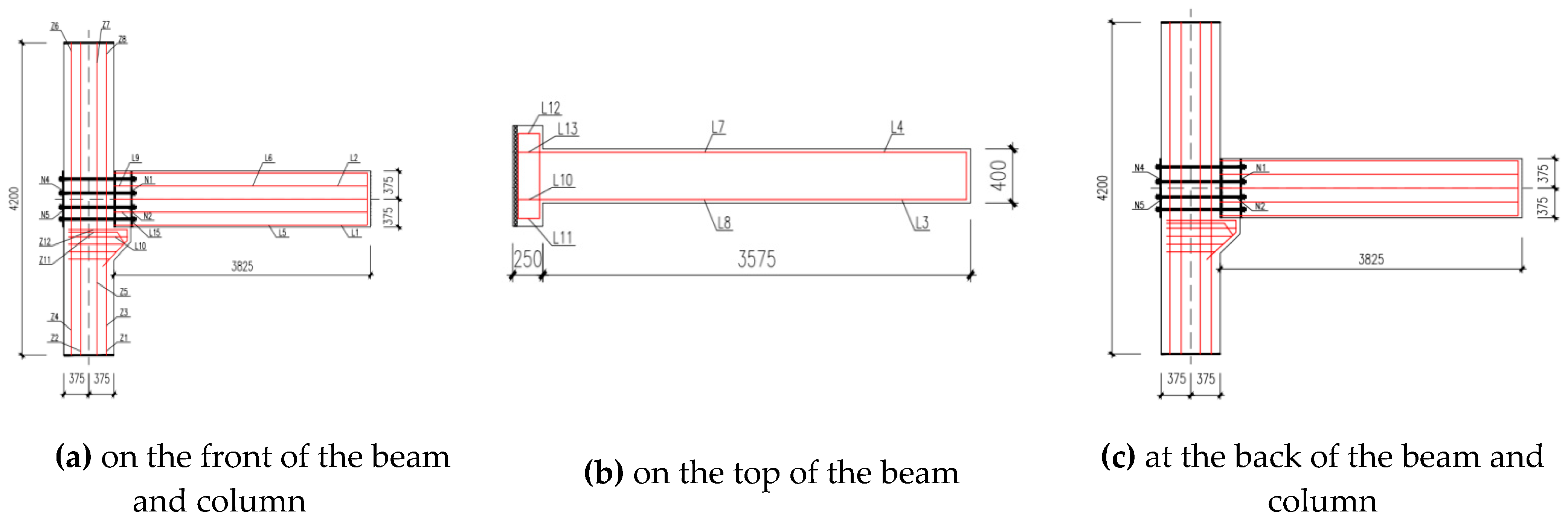
3.2. Layout of Strain Measurement Gauges
Strain measurement gauges are placed at key positions including the end of the column, the node area, the core area, the beam end, the ox leg, etc., to understand the variation of strain and stress of specimen under loads. The same branch of gauges with maximum electric current of 125A are adopted in this experiment. The positions of gauges are shown in
Figure 5: L1-L10 is used to measure the distribution of stress of reinforced concrete beams under loads; L11-L15 is used to measure the magnitude and direction of the main strain in the core region of the joints; Z1-Z8 is used to measure the distribution of strain of column under constant axial force; N1-N6 measures the stress–strain distribution of bolts under the action of horizontal load and vertical load.
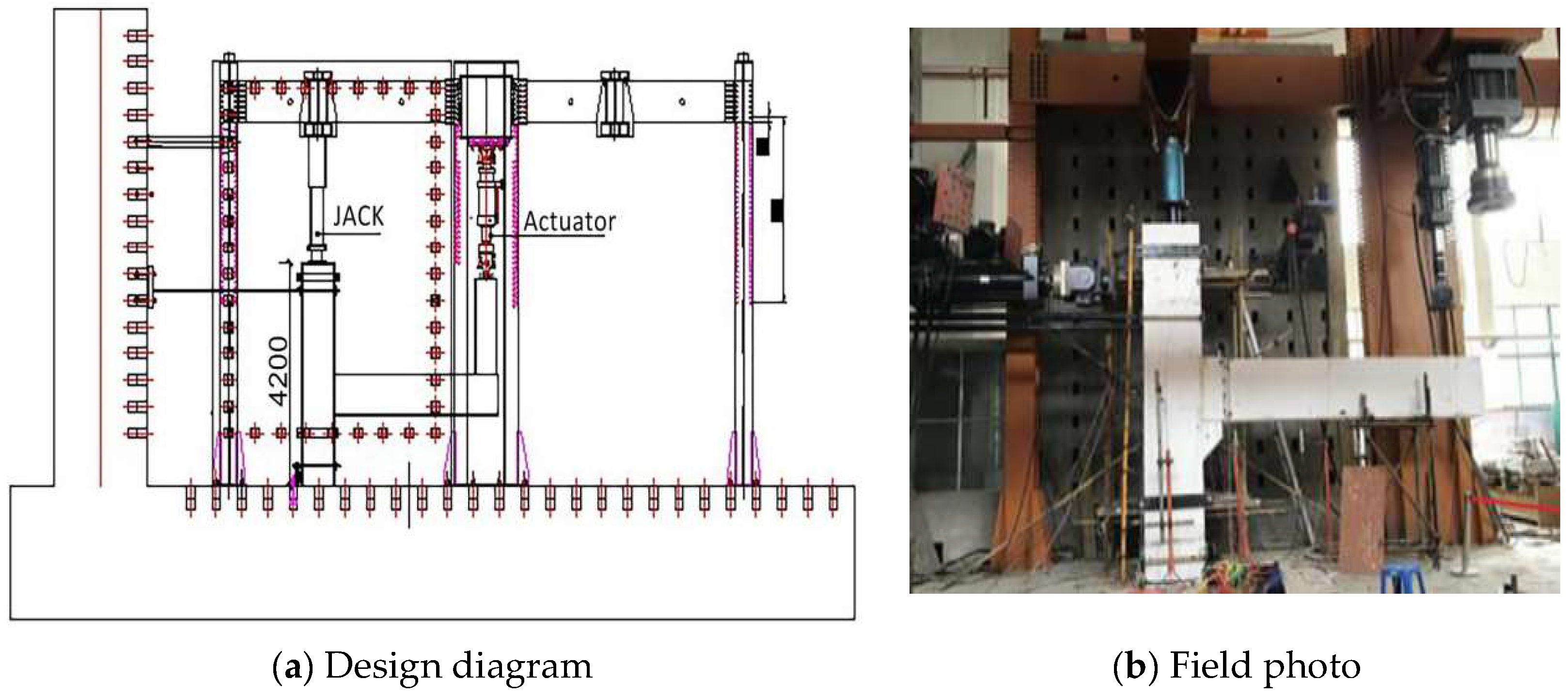
3.3. Test Loading Scheme
The pseudo static test of low-cycle repeated loading is adopted for this study. The test equipment is loaded by Beijing Foli electro-hydraulic servo loading system, with the displacement stroke of the actuator.
This experiment took the beam end, the connection between corbel and bolt and the joint core, as the research object and used the mixed loading method to apply 670 kN of axial force to the column top (see
Figure 6).
3.4. Test Loading System
According to the Code of Seismic Test for Buildings (JGJ/T101-2015) [
22], the load-displacement double-control method was adopted in the test. By analyzing and calculating the specimens before yield, the load control was used and graded loading was applied. Each grade was loaded 5 kN and cycled once, and the differential loading was reduced before approximating to cracking and yield load. Displacement control was used when the specimens yielded, with each grade of load cycled 3 times, and the maximum displacement value of the specimen taken as the deformation value when the specimens yielded. The multiple of the displacement was used as the grade difference to control the loading until the bearing capacity of the specimen dropped to the point that it was not suitable for further loading.
3.5. Test Results
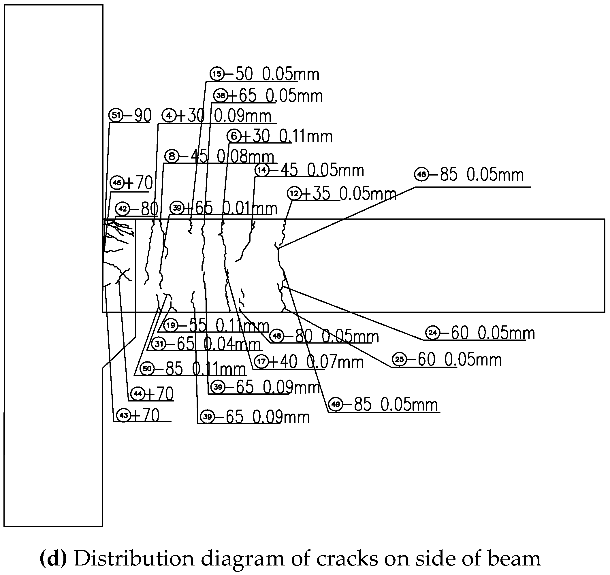
The test loading direction stipulates that pushing down refers to positive direction (+), pulling up refers to the negative direction (−), and the loading order is positive before negative. Considering the dead weight of the beam, the tension is greater than 15 kN of thrust. At the initial stage of loading, the deformation and strain of the specimen did not change significantly, and no cracks occurred. When loaded to +30 kN, the first crack appeared at the beam end of the joint core area, and a crack of 0.1 mm wide appeared near the bearing plate of column. Under reverse loading of −45 kN, the first crack appeared before it closed, and the crack on the lower surface of the beam is symmetric with the crack on the upper surface of the beam. The mechanical properties and phenomena refer to the upper surface of the beam. When the force was loaded to +40 kN, the beam end continued to generate cracks under tension, and the crack width went on increasing near the bearing plate, with a maximum width of 1.5 mm. The surface strain of steel reinforcement in the tension area increased gradually, and the strain and residual deformation of the steel plate and bolt also increased. When the reverse loading was −55 kN, the corresponding cracks on the beam surface closed, but the cracks near the joint core area and bolts did not close completely. When the force was loaded to +75 kN, the beam produced large displacement and deformation, the width of the crack at the intersection of the T-shaped section of beam end and the column continued to increase to 1.8 mm, and the stress of the reinforced rebar on the beam increased suddenly to its limit. At this time, force loading was changed into displacement loading. Three levels of displacement loading of ±95 mm, ±115 mm, and ±135 mm are carried out and each level cycles three times respectively. With the load increasing, the number and width of cracks increases, and thus gradually forming through cracks as shown in
Figure 7.
The final peak load is +82 kN, the peak displacement is +78 mm, the ultimate load is +72 kN (greater than 85% of the peak), and the corresponding ultimate displacement is +134 mm. During the test, there was no crack in the precast concrete column. After the precast concrete beam yields, the value of stress at connected high-strength bolts does not reach the yield strength.
4. Analysis and Comparison of Test Results
4.1. Joint Yield and Failure Load
The ultimate displacement and the ultimate bending moment are determined by the geometric drawing method. After comparison in
Table 3, the ultimate bending moment of the test differed greatly from the theoretical value, mainly because the concrete grade of the T-shaped end of the beam is C40, while the concrete grade of the column is C80. Due to the punching failure in the core area at the t-shaped end of the precast concrete beam, the ultimate bending moment at the beam end is much lower than the theoretical bending moment value. Therefore, although the high-strength bolt produces a large stress, it is not the expected high-strength bolt that produces a large deformation, resulting in a large angular deformation of beam–column joints.
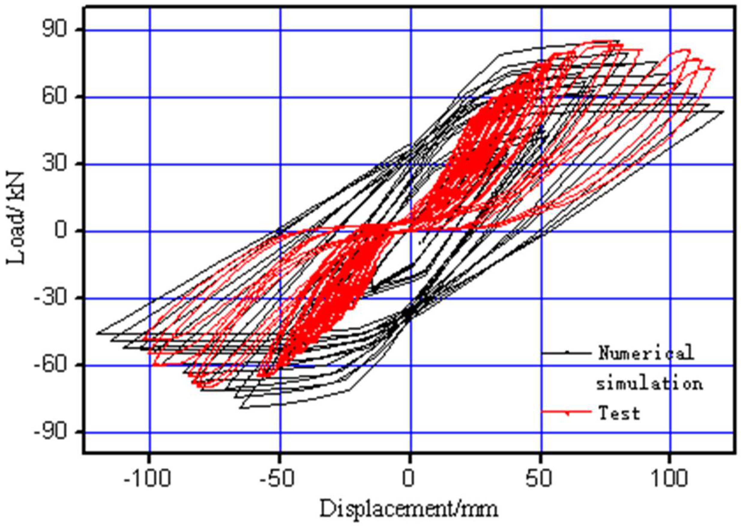
4.2. Hysteretic Curve
Finite element simulation of the mechanical properties of new dry-type connection joint were conducted using ANSYS software. Integral modeling is adopted in this study. Reinforcement units were regarded as subunits permeated in the concrete, of which mechanical properties can be superimposed on the plain concrete. The solid 65 units with kinematic hardening in the built-in material database of ANSYS software was selected as constitutive model. Parameters are set as follows: the elastic modulus was set to be 34 GPa; the poisson ratio was set to be 0.2; the transfer coefficient of crack opening and crack closure were set to be 0.35 and 1; meanwhile, the concrete compressive strength of beams and columns were set to be 32 MPa and 54 MPa, respectively. The common 3-D 4-joint unit solid 182 was chosen for high-strength bolts. The main model property was two-linear mixed-hardening. The elastic modulus was set to be 200 GPa; the poisson ratio was set to be 0.45; the yield strength was set to be 618 MPa and the strain-hardening modulus was set to be 20,000. In-plane constraints and normal constraints were set on the top and at the bottom of the concrete column. End face of concrete beam was set as loading end. The partition type of the model is free partition, and the mesh size of screw, concrete beam, and column was 25 mm and 100 mm, respectively. ADD action was applied to nuts and screws in order to make them work together.
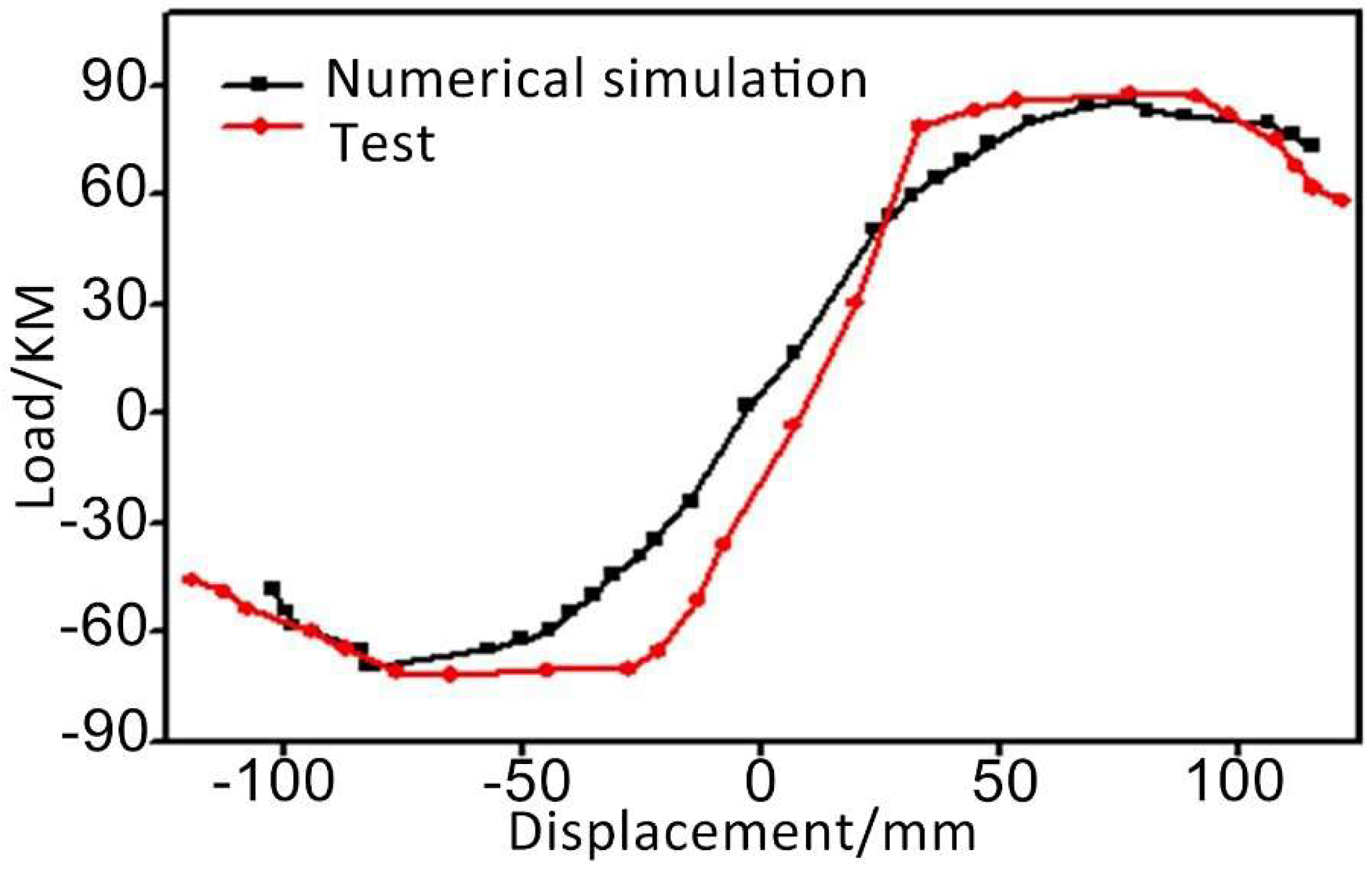
The hysteretic curve of finite element simulation and experiments are compared (in
Figure 8).
The hysteretic loop is full in the simulated state, which is different from the experimental results to some extent, because the numerical model material is relatively ideal, and the failure of the component caused by the uneven mechanical properties of the material is not considered in the loading process. In the actual test process, at the initial stage of loading, the force and displacement show a linear relationship. With increasing force, the area of the hysteresis ring also increases gradually, and the core area of the joint of the member is severely deformed by extrusion and has obvious shear failure. There is a certain gap with finite element simulation analysis, but the hysteretic loop obtained by the test is arched, indicating that the plastic deformation capacity of the whole component is still stronger, and under low-cycle repeated loading the joint is better at absorbing seismic energy.
4.3. Skeleton Curve
The skeleton curves in the experimental state and the simulated state were compared (see
Figure 9).
The skeleton curve in the experimental state is relatively consistent with the skeleton curve in the simulated state. Both of them went through the stages of spring-yield-intensify-destroy. The comparison between the model and the test shows that the new type of assembled joint can ensure good seismic performance under the condition of a strongly bolted connection.
6. Conclusions and Future Research
6.1. Conclusions
In this study, a range of pseudo static tests of beam–column connection joints were carried out. From the test results, the mechanical properties and performance were evaluated and compared. The following conclusions can be drawn.
(1) The new beam–column joint connected by high-strength bolts has high rotation rigidity, but still has good rotational capability and a reasonable amount of ductility.
(2) Due to the high strength of the connection bolts and the fact that the concrete beam–column intersection is easily extruded under increased loading, the concrete beam end is liable to be destroyed first by punching before the bolts fail. Therefore, when designing the beam end, it is necessary to pay attention to avoid the reduction of capacity due to the punching failure of beam end.
(3) With high bolt connection strength, the new assembled joint can ensure that under the action of low cyclic repeated load, the whole assembled structural system maintains a full hysteretic curve, can better absorb seismic energy, and is structurally earthquake resistant.
(4) By comparing some dry-type connection joints, the new assembled joint connected by high-strength bolts in this test are more convenient to install and disassemble, have better bearing capacity, ductility and energy consumption capability, and are more suitable for an actual seismic event.
The results provide a foundation for the analysis of assembled structural framework systems based on different forms of dry-type connection joints.
6.2. Future Research
(1) It is found that the connection quality of the high strength bolt has a great influence on the performance of the new dry-type connection joint. The tests reveal that in actual operation the connection between the bolt on the beam and the bolt on the column is not sufficiently complete. From this experimental experience, more attention should be paid to dimensional accuracy when designing and constructing components.
(2) It is found from the tests that the connection bolts are very strong so that the concrete beam is destroyed before the bolt connection fails. To help resolve this imbalance, future research could reduce the strength grade of the high-strength bolts, or the beam end in contact with the column could be equipped with more anti-punching shear rebar.


