Theoretical Study of an Intermittent Water-Ammonia Absorption Solar System for Small Power Ice Production


1
Mechanic Engineering Department, Escola Superior de Tecnologia de Setúbal/IPS Campus do IPS, Estefanilha, 2760-761 Setúbal, Portugal
2
CINEA-IPS, Energy and Environment Research Centre, 2760-761 Setúbal, Portugal
3
Escola Superior de Tecnologia de Setúbal/IPS, IPS Campus, Estefanilha, 2760-761 Setúbal, Portugal
*
Author to whom correspondence should be addressed.
Sustainability 2019, 11(12), 3346; https://doi.org/10.3390/su11123346
Submission received: 6 March 2019
/
Revised: 12 May 2019
/
Accepted: 6 June 2019
/
Published: 17 June 2019
(This article belongs to the Section Energy Sustainability)
Abstract
:This article is dedicated to the design, calculation and dimensioning of a small powered refrigeration system (132W) which produces ice bars (freezing) using solar thermal power, and resorts to an intermittent cycle absorption circuit with a water-ammonia mixture (H2O-NH3). The aim of this equipment is to minimize problems faced in places where there is no electric network to supply traditional refrigeration systems which preserve perishable products produced or stocked there, as well as drugs (vaccines), namely for specific regions of developing countries. The system developed can be divided into two parts. The intermittent cycle absorption refrigeration system uses a binary water-ammonia solution (H2O-NH3), where water is the absorber and the ammonia is the coolant and the thermal solar system. This is made up of CPC flat plate thermal collectors or vacuum tubes in which solar energy heats the water that circulates in the primary circuit. In the absorption circulation system, circulation occurs in a natural way due to the fluids affinity, and the temperature and pressure internal variations. This article shows the assumptions underlying the conception, calculation and dimensioning of the system’s construction.
1. Introduction
Nowadays, refrigeration is generally associated with, more or less, complex and sophisticated systems. Nevertheless, the importance of low temperature has been known since pre-historic times to store food in caves with humid walls to preserve it, taking advantage of the natural cooling effect. Since those times and until the beginning of the 20th century, people have collected natural ice during winter time and have stored it in wine cellars, and later in places allowing the preservation of the ice for one year or more [1]. In the 1850s, the United States and Europe were already trading important amounts of natural ice. The development of modern refrigeration, as society knows it today, started at the end of the 19th century. In the most ordinary refrigeration process, a substance designated as a refrigerant is subject to a sequence of phases which lower the fluid’s temperature to withdraw heat from the fluids or bodies that need to be cooled down. Currently, the main refrigeration methods used are the vapor compression cycle, the absorption cycle, air cycle vapour jet and thermoelectric system [2]. The well-known vapor compression cycle has a vast range of applications from domestic refrigeration systems to vast industrial systems [3]. To operate the absorption cycle refrigeration systems, these systems need a hot source at high temperatures, being thus an interesting process when an important thermal source as solar energy is available. These systems use a binary liquid solution, made of a refrigerant and an absorbent. The refrigerant must have a high chemical affinity with the absorbent. Absorption systems are economically viable when there is a cheap source of thermal energy at the appropriate temperatures [4].
2. Motivation
Currently, cold refrigeration or freezing is the most often used technique by human beings to preserve perishable products, as well as vaccines. Preservation through cold can even be regarded as an indispensable technique for human subsistence as it currently exists. In regards to refrigeration systems, resorting to solar energy can be a viable solution for places where electric energy obtained through traditional sources is not available, but where there is abundant solar radiation, namely in remote areas of difficult access, and near the tropics. Thus, using absorption refrigeration systems which use solar energy as a thermal source can be a solution with high potential for success to answer the needs of those developing areas, namely for ice production to preserve perishable products, fisheries, vaccines, etc. Thus, an intermittent absorption refrigeration system using solar energy as a low cost thermal source is a very interesting issue as no electric power is used (in our intermittent cycle) and a eco-friendly binary mixture can be used, such as the water-ammonia (H2O-NH3) [5]. Using solar energy as thermal source to activate the refrigeration system cycle also has interesting advantages, such as, a free, clean and endless energy source which does not present risks for its users and is relatively easy to obtain [6]. This article is dedicated to a new development of a rectifier with a low cost small absorption refrigeration system with an intermittent cycle using solar energy where the fluid used is a binary mixture of water and ammonia (H2O-NH3) for ice production.
3. Refrigeration Methods
The vapour compression cycle has a vast range of applications from domestic refrigeration systems to vast industrial systems [7]. The absorption cycle refrigeration systems are used in special circumstances as they need a hot source at high and moderate temperatures [8]. There are applications in which heat is available or when it is not available, there is a mechanical force, such as plants of chemical products, air conditioning and some domestic fridges [9]. In the air cycle, the temperature is lowered though an expansion process in which the operation is executed by the air. This refrigeration method was used for many years within the maritime area because of its safety. Currently, this refrigeration method is used to refrigerate the cabins of an airplane. The steam jet refrigeration systems were very popular at specific moments in time because they can directly be operated by a steam supply at moderate pressure and did not need toxic gases to work. Despite this, currently, it is not very often used. The thermoelectric refrigeration method operated in accordance to the Peltier effect principle, i.e., the cooling effect is produced when an electric current goes through a combination of two different metals. This method’s efficiency is low due to the material available. Nevertheless, it is used when low efficiency is not an issue, such as very small ice-boxes, and instruments to measure the dew point, among others [1].
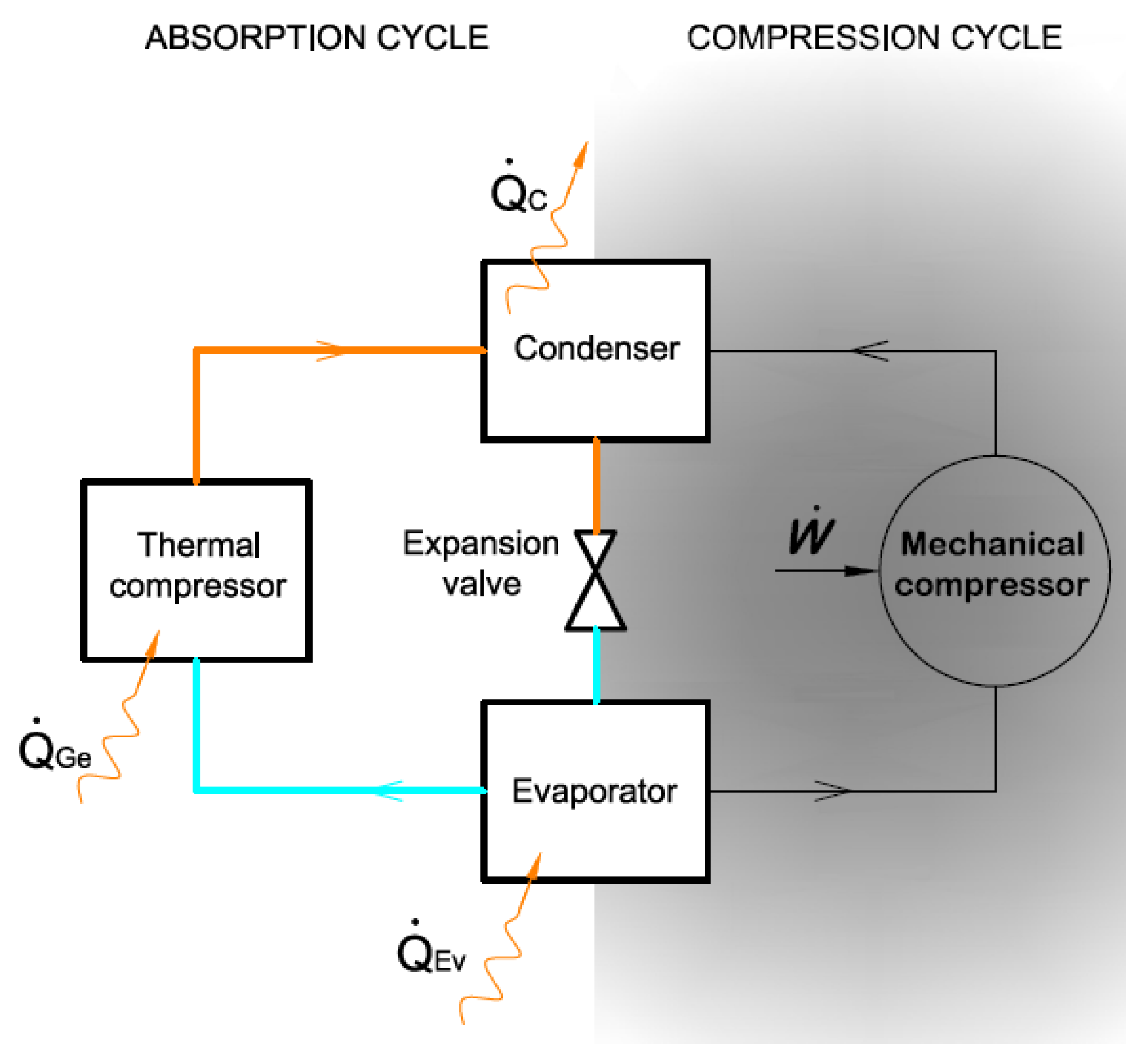
Both in compression refrigeration systems and in absorption refrigeration systems, the refrigeration effect is produced by making the refrigerant evaporate at low temperatures appropriate to each situation. The main difference is in the compression area, where the steam mechanical compressor is replaced by a thermal compressor, as shown in the following Figure 1.
In absorption refrigeration systems, a binary liquid solution is used which is composed of the refrigerant and the absorbent. The refrigerant must have a highly chemical affinity with the absorbent. In these systems, only thermal energy is exchanged with the surrounding environment as there are no mechanical energy exchanges [10]. The absorption system is economically viable when a non-expensive source of thermal energy is present at temperatures between 100 °C and 200 °C [4].
4. Absorption Cycles
Paulo Otto Beyer [11] developed an absorption refrigeration system to produce ice using solar energy. The equipment used is an absorption refrigeration system in which the operating refrigerant is water-ammonia (H2O-NH3) and coupled to this system is a solar thermal system composed of compound parabolic concentrators (CPC) solar collectors. These allow a concentration of the radiation on an oil absorber, as it operates at higher temperatures (about 130 °C) to have a higher performance. This system had a daily project nominal production of 100 kg.
Jaroslav Vanek, Mark Moth Greene and Steven Vanek [12] developed an ice production system with an intermittent regime absorption cycle which operates with a calcium-ammonia chloride (CaCI2-NH3), and where the absorbing fluid is calcium chloride and the refrigerant is ammonia. This equipment aims at preserving vaccines, milk, meat, dairy products, vegetables, etc., using solar energy, which has almost no mobile parts and no batteries. Basically, it is comprised of a galvanized steel black tube generator, a coil condenser, submerged in water and an ice-box evaporation container in which liquid ammonia is collected during the generation. This ice production equipment operates the day/night cycle, generating ammonia steam during the day and reabsorbing it at night which makes the refrigeration happen. Each cycle can form up to 4.5 kg of ice.
Further, a solar intermittent refrigeration system for ice production was developed in Centro de Investigación en Energía of the Universidad Nacional Autónoma de México. This system operates with the ammonia/lithium nitrate mixture. This system has a nominal capacity of 8 kg of ice/day and consists of a cylindrical parabolic collector acting as a generator–absorber with evaporator temperatures of −11 °C and the solar coefficient of performance was found to be 0.08. In this system, the coefficient of performance increases with the increment of solar radiation and the solution concentration [13].
To improve the efficiency of the ice production equipment previously developed, David Beasely and Steven Vanek [14] presented a new concept which consisted of removing the ice-box ammonia storage container and replacing it with an evaporator with a manual rolling valve. The generator and the condenser are the same as the ones in the initial model. With the condensate storage container outside the ice-box, there is a larger volume for ice production inside the box. The ice-box performance is also increased in case it is impossible to form ice, as the ice formed during the night cycle shall guarantee the refrigerated thermal space. They also added a 1-inch thick layer of foam insulation inside the ice-box to decrease exchanges between the environment and its interior. With these changes to the initial system, the ice starts to form after 15 to 20 minutes when ammonia is present in the evaporator [14].
The intermittent solar ammonia absorption cycle (ISAAC) [15] is another ice production system developed to fully operate without electricity. Its operation is based on the intermittent absorption refrigeration technology in which the fluids are water and ammonia (H2O-NH3), and water being the absorber and ammonia being the refrigerant. This system is easy to operate and highly durable. The system was developed by the Energy Concepts Company [www.energy-concepts.com], from Annapolis, Maryland and produced and promoted by the Solar Ice company [www.solaricemaker.com]. The system operates on a diurnal cycle in which the refrigerant, being ammonia, is separated from the absorber, being water due to the solar energy incidence on the generator. ISAAC operates through the repositioning (in the morning and in the early evening) 5 manual valves which are part of the system. This project comprises a 2.44 m by 4.88 m solar collector. The system produces 50kg of ice blocks per sunny day. These block dimensions are 5 × 24 × 66cm, and 8.3 kg of weight. The ice produced is used to preserve milk which is inside a metal container in areas of the USA. Fifty kilos of ice are sufficient to preserve 100 l of milk per day.
5. Description of The Equipment Developed
5.1. Aim
The equipment developed is a small, low cost, intermittent absorption refrigeration system using solar energy in which the fluid used is a binary mixture of water and ammonia (H2O-NH3) to produce ice for the preservation of perishable products and vaccines. Its preferential application shall be in developing areas with low economic resources and lack of electric energy distributed by traditional methods. The choice of the water and ammonia (H2O-NH3) binary solution is due to the fact that this mixture has highly interesting features and advantages for this application [16], namely: i) Ammonia has an evaporation temperature of –33.3 °C at atmospheric pressure, a high refrigeration capacity, and it does not contribute to the ozone layer destruction (ODP = 0). It also does not produce greenhouse gas emissions (GWP = 0) [17] and has a high affinity with water [18]; ii) Water is a clean, abundant, renewable, non-expensive, non-toxic, non-pollutant and it does not contribute to the ozone layer destruction (ODP = 0), and it produces zero greenhouse gas emissions (GWP = 0) and it is a proper absorbent of ammonia. The use of solar energy as the thermal source for the refrigeration system is due to the fact that the countries where people are interested in installing this equipment have high solar radiation and lack a public electric power supply. The system operation is an intermittent one (diurnal generation and night refrigeration). The condenser refrigeration is performed by water natural convection. As a thermal source to be applied to the generator, thermal energy (heat) obtained from CPC or vacuum tubes stationary solar collectors was used. These two types of collectors were studied as they used relatively high temperatures with reduced lowers [8,19].
5.2. Ice Production System Design
In this absorption cycle (H2O-NH3), the heat source used to heat the fluid in the generator comes from the solar energy on one or several solar collectors. The system operation is an intermittent one having diurnal generation and night refrigeration, and no other type of energy besides solar energy is used. The system developed comprises two subsystems: The solar one and the absorption refrigeration one. The main components needed for its operation are shown in Figure 2.
The components comprising the mentioned system are: Solar thermal collector, solar thermal subsystem piping, generator or absorber, condenser, condensate tank, ice-box and evaporator, rolling device, rectifier and refrigeration subsystem piping. When the intermittent absorption refrigerating system operates at temperatures below 0 °C, the problem is the possible formation of ice due to the presence of water, thus blocking the passage of refrigerant, and in extreme cases may damage parts of the system. For this reason, the ammonia vapor leaving the generator should have the lowest water content possible. This study solved this problem by introducing a rectifier downstream of the generator, which makes the ammonia vapor purer [20].
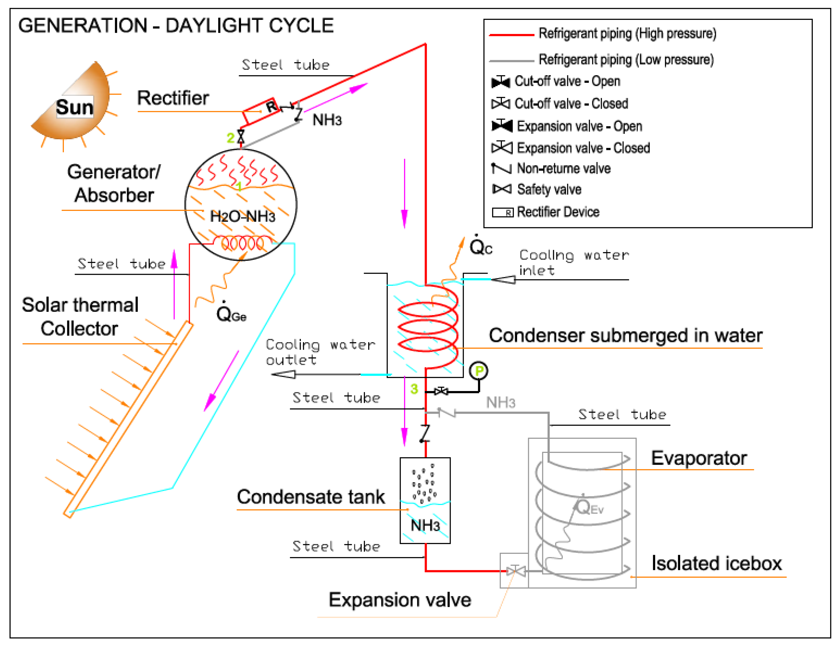
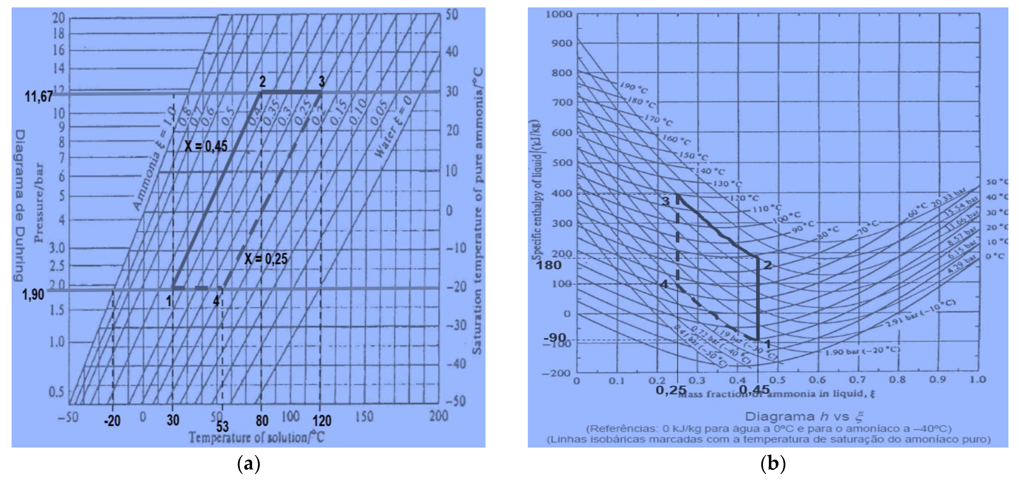
In the generation diurnal cycle (Figure 3), the solar radiation is used to introduce heat into the cycle. The cycle starts when the strong water-ammonia mixture, with a concentration of 45% of ammonia and located in the generator/absorber, is heated by the solar thermal system heat supply which makes the temperature and the pressure increase until they reach the saturation point of the mixture at condensation pressure (Pc) (phase 1–2), and is controlled by a pressure adjustable valve. Then, the temperatures continues increasing and the separation/evaporation of the ammonia from the solution starts until it reaches a concentration of 0.25 (phase 2–3). Also within this phase, the ammonia vapor exiting the generator goes through the rectifier and the non-return valve. The rectifier allows guaranteeing a greater purity of the ammonia vapor [20]. Following this, the ammonia vapor is forwarded to the condenser where it dissipates heat to a less hot environment (water) and thus condensates, being then stored in the condensate tank, until the refrigeration phase starts. In this cycle, there is no passage of ammonia to the evaporator because the valves located upstream and downstream of the said evaporator are non-return valves and thus do not allow the reverse direction.
The night cycle (Figure 4) takes place when the temperature and the pressure of the generator/absorber decrease with the evaporator pressure (Pe) (phase 3–4). This cycle can then start by opening the adjustable rolling valve upstream of the evaporator thus allowing the liquid ammonia to be stored in the condensate tank inside the evaporator at pressure (Pe). This cools the ice-box by removing the existing heat and finally, goes back to the generator/absorber (phase 4–1) where it mixes with the solution due to its high affinity with water. In this direction, there are also anti-return valves controlling the passage of the ammonia.
5.3. System Thermodynamic Calculations
The system studies allow removing heat from the ice-box with a specific cooling power to produce ice bars. As reference climatic data for this study, the authors chose the data for the month of July and the city of Beja, as it is one of the country’s areas with the highest monthly values of daily average horizontal radiation, environment temperature and network water temperature [21]. These can be the most unfavorable conditions as a reference for African countries which have a higher level of radiation. It is thus considered that the system operates the entire day. Below is the study of the system for the month of July.
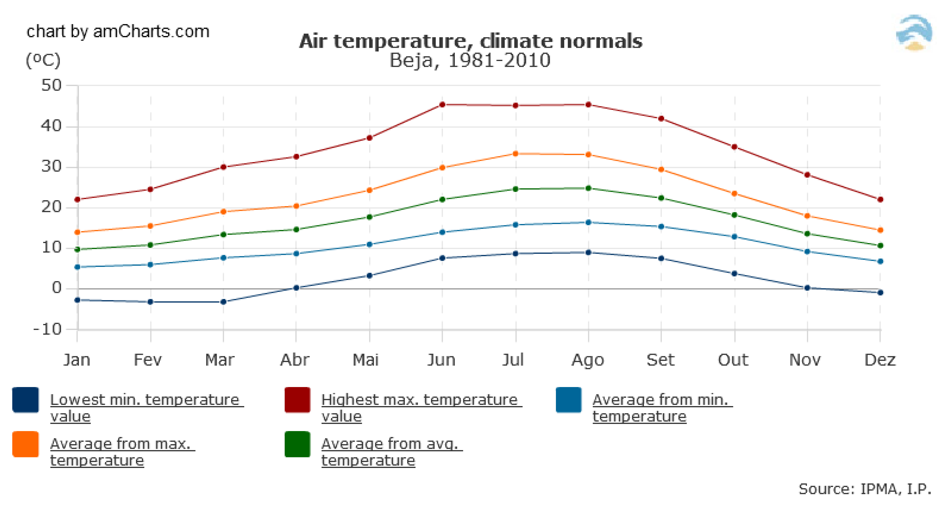
Beja is a city located in Portugal, in the Alentejo region, which is a sub-region of the Lower Alentejo. Beja has about 28.000 inhabitants. The climate of Beja is influenced by its distance from the coast. Although mild by European standards, the winters in Beja are relatively cold, while summers are long and hot. According to Figure 5, the average high temperature in January is approximately 14 °C, while July and August highs are approximately 33 °C. The average January low temperature is approximately 6 °C and in July and August, it is 16 °C. The average annual temperature is approximately 16 °C. In this city, snow can occasionally fall. The total average precipitation in one year is 558mm. In recent years, the weather has been dry in Portugal.
5.3.1. Thermal Charge Calculation
To calculate the power to be removed from the product during refrigeration and freezing, the following expressions are used [22]:
For refrigeration (sensible heat removal):
in which:
For freezing (sensible and latent heat removal):
in which:
| Cooling capacity [kW] | |
| Mass flow rate [kg/s] | |
| - | Specific heat before freezing [kJ/kg K] |
| Initial temperature [K] | |
| - | Final temperature [K] |
| Freezer capacity [kW] | |
| Mass flow rate [kg/s] | |
| Latent heat of solidification/ liquefaction [kJ/kg] | |
| Initial temperature [K] | |
| Freezer temperature [K] | |
| Final temperature [K] | |
| Specific heat before freezing [kJ/kg K] | |
| Specific heat after freezing [kJ/kg K] |
5.3.2. Solar Thermal Power Calculation
The absorption refrigeration system cycle can be analyzed in terms of its efficiency through the coefficient of performance (COP), a dimensionless quantity used to assess the relation between the refrigeration capacity obtained and the solar thermal power supplied to the generator, being set by the following expression [8,23]:
in which:
| Coefficient of Performance [dimensionless] | |
| Useful freezer capacity [W] | |
| Solar heat supplied [W] |
Considering a value for the COP of the absorption thermal system and knowing the freezing power value, the solar power needed for the absorption refrigeration cycle can be obtained through the following expression:
5.4. Monthly Energy Demands Calculation
Below are calculated monthly energy demands () for achieving the nominal refrigeration capacity, using the solar energy product demands for the refrigeration cycle and the days corresponding to the months in question. According to the following expression [24]:
in which:
| Monthly Energy Demands [MJ] | |
| Solar heat supplied [MJ] | |
| Solar hours [s] |
5.4.1. Collector Solar Area Calculation
After calculating the energy needs for each month, which can be shown through graphs or tables, the consumption diagram can be drawn. Ideally this diagram shall correspond, as much as possible, to the solar incidence diagram throughout the year.
Thus, for each month, the solar energy can be calculated which is available or consumed, and which is sometimes higher than the unit and other times lower between the different months. Thus the collector must be adjusted, according to the Table 1 [24]. The values for the slope or inclination presented are the inclinations given to the collectors, according to the time of year and the use for which they are intended.
Being that the absorption refrigeration systems shall operate the 12 months of the year to produce cold, the previous table shows that the appropriate stationary flat, plate thermal solar collectors’ inclination shall be the one corresponding to the whole year (Latitude – 5°).
The expression determining the optimal inclination is:
In which:
| Optimal inclination [°] | |
| Latitude angle of the place [°] | |
| Angle of inclination [°] |
5.4.2. Useful Energy Calculation
The useful energy or theoretic total energy () on each m2 of the collectors area inclined in an average day of each month is obtained through the following expression [24]:
in which:
| Average horizontal Irradiation monthly adjusted [MJ/m2] | |
| Average horizontal Irradiation monthly [MJ/m2] | |
| Correction coefficient [dimensionless] |
5.4.3. Collector Efficiency Calculation
Calculation of the collector theoretical efficiency () is based on the collector’s expression, being the optical performance and the collector loss coefficient supplied by the equipment manufacturer:
in which:
or
The following corrections must be taken into account in this expression [24].
| Theoretical collector efficiency [%] | |
| Irradiation Factor [dimensionless] | |
| Irradiance, total solar energy incident on upper surface of sloping collector structure [W/m2] | |
| Cover transmittance [dimensionless] | |
| Absorptance [dimensionless] | |
| Overall heat loss coefficient of collector [W/m2 °C] | |
| Average fluid temperature [°C] | |
| Atmospheric temperature [°C] |
| Optical performance [dimensionless] | |
| Loss coefficient [W/m2 °C] |
Being the theoretical efficiency calculated based on the assumption that the rays reach the collector at right angles, which in fact does not take place as these form a variable angle throughout the day, and thus (α) decreases through the experimental factor () equals 0.97 (or 0.95 in double cover collectors).
The effect of the dirt and ageing of the transparent cover, if existing, makes (τ) also decrease due to a dirt factor () equal to 0.97.
Thus to find the expression of the actual efficiency of a collector with cover, the product needs to be multiplied by the corresponding factors shown in the previous points.
in which:
| Actual collector efficiency [%] | |
| Experimental factor [dimensionless] | |
| Dirt factor [dimensionless] |
In general, factors (F′(τ.α)) and (F′UL), which are the optical efficiency and the losses coefficient, respectively are supplied by the collector’s manufacturer, as it is enough to insert the data related to the useful intensity and environment temperature.
5.4.4. Theoretical Collecting Surface Area Calculation
To calculate the theoretical collecting surface area (), the quotient of the monthly energy demands () is calculated and the energy captured during the months per m2 of collector () pursuant to the following equation:
in which:
| Theoretical collecting surface area [m2] | |
| Monthly energy demands [MJ] | |
| Energy captured during the month per m2 of collector [MJ/m2] |
5.4.5. Collectors Theoretical Number Calculation
Knowing the theoretical collecting surface area () needed to meet the monthly energy demands, the collector is chosen namely because of the temperatures it can reach, which are related to the thermal efficiency and the losses coefficient. The lower the losses, the greater the temperatures achieved.
Thus, knowing the useful area of the collector (,) the theoretical number of collectors required () are calculated for each month through the following expression:
in which:
| Theoretical number of collectors required [dimensionless] | |
| Theoretical collecting surface area [m2] | |
| Useful area of collector [m2] |
To calculate the actual number of collectors () to be applied to the system, the number of collectors related to the months with less solar radiation must be taken into account. Nevertheless, the study must be carried out in order to allocate a quantity that respects the cost-benefit factor.
5.4.6. Effective Power Taken Per Month Calculation
After knowing the actual number of collectors to be applied to the solar system, this study calculated the effective power taken per month () as the result of energy captured during the month per m2 of the collector (), the useful area of the collector () e, and the actual number of collectors applied to the system () using the following expression:
in which:
| Effective power taken per month [MJ/m2] | |
| Energy captured during the month per m2 of collector [MJ/m2] | |
| Useful area of collector [m2] | |
| Actual number of collectors [dimensionless] |
5.4.7. Collector Dimensioning
To carry out the coil dimensioning of the device, the following data was used [25]:
The power dissipated in the condenser is obtained through the following expression:
And
in which:
To determine the global heat transfer coefficient, the following expression is used [25]:
in which:
| Thermal power rejected by the condenser for the environment [W] | |
| Heat exchange area [m2] | |
| Global heat transfer coefficient [W/m2 °C] | |
| Difference between indoor and outdoor temperature [°C] | |
| Pipe radius [m] | |
| Length of piping [m] |
| Global heat transfer coefficient [W/m2 °C] | |
| Surface coefficient of heat transfer by external convection [W/m2 °C] | |
| Surface coefficient of heat transfer by internal convection [W/m2 °C] | |
| Thermal conductivity of the different materials constituting the wall [W/m °C] | |
| Internal pipe area [m2] | |
| External pipe area [m2] | |
| Internal pipe radius [m] | |
| External pipe radius [m] | |
| Length of piping [m] |
The convection coefficient values (hi) e (he) must be calculated. To calculate (he), which is the outer cooling fluid, the expression for natural convection was used [26]:
in which:
The expression to calculate the Nusselt number used in natural convection for horizontal cylinders is [25]:
in which:
The Rayleigh number is obtained through the following expression [25]:
in which:
The expression used to calculate the convection coefficient () for condensation inside the horizontal tubes [27]:
in which:
| Outer diameter of the pipe [m] | |
| Nusselt number [dimensionless] |
| Rayleigh number [dimensionless] | |
| Prandt number [dimensionless] |
| Gravitational acceleration [m/s2] | |
| Coefficient of volume expansion [dimensionless] | |
| Fluid density [kg/m3] | |
| Specific heat of the fluid [J/kg °C] | |
| Dynamic Viscosity [kg/ms] | |
| Thermal Conductivity [W/m °C] | |
| External diameter of the pipe [m] |
| Convection coefficient for condensation inside the horizontal tubes [W/m2 °C] | |
| Gravitational acceleration [m/s2] | |
| Fluid density in the liquid phase [kg/m3] | |
| Fluid density in the vapour phase [kg/m3] | |
| Thermal conductivity of the fluid in the liquid phase [W/m °C] | |
| Dynamic liquid viscosity [kg/ms] | |
| Specific fluid heat in the liquid phase [J/kg °C] | |
| Enthalpy of vaporization [kJ/kg] | |
| Fluid saturation temperature [°C] | |
| Temperature of the surface of the tube in contact with the fluid [°C] |
5.5. Dimensioning Assumptions
Being that the purpose of the refrigeration system is the production of ice, the assumptions shown in Table 2 were adopted to calculate the refrigerating power:
To calculate the solar power needed for the refrigeration system, the authors determined a COP equal to 0.5 as this is a value close to the one present in works on this kind of absorption refrigeration systems [16,28]. After knowing the energy demand for each month of the year so that the absorption refrigeration system operates, the authors calculated the solar system dimensioning able to meet these needs by using CPC or vacuum tubes collectors. One important issue in this calculation is the heat losses. For this system, estimated heat losses can reach a maximum of 20% to 30% of total heat collected by the solar receiver [29,30,31].
6. Results
Table 3 shows the monthly energy needs for the equipment and the solar energy collected for each month of the year by the different types of collectors. It is verified that only 1 collector, of each type, is necessary to guarantee the energy needs of the equipment for the month of greatest solar irradiation, July. Nevertheless, the vacuum tube collector type guarantees two times the demand.
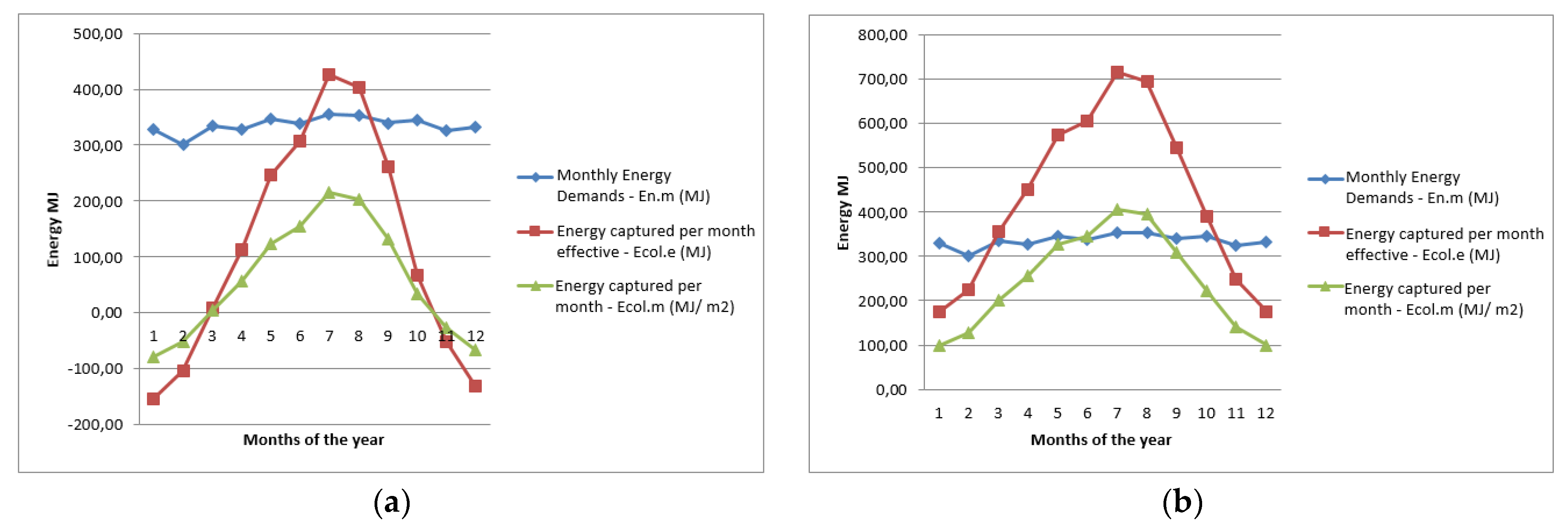
To compare both types of solar collectors applied (CPC collector (a) versus vacuum tube collector (b)), below are two graphics showing the energy needs curve of the refrigeration system, the curve of the energy captured per month effective and the curve of the energy captured per normal month.
Most months of the year, a single vacuum tube collector is enough to extract the energy needs for the system, except for the two first and the last months of the year (Figure 6b). it is observed that this kind of collector coupled with the absorption refrigeration system is more appropriate than the CPC collector, despite the fact that it is more expensive. Related to the refrigeration system, are presented the Duhring (a) and Merkel-Bosnjakovic (b) diagrams (Figure 7) [1] for the water-ammonia solution, as well as the Mollier diagram (Figure 8) for the ammonia (NH3).
Table 4 shows the summary of energy balances in the different components of the system:
7. Construction Solution
8. Conclusions
A small intermittent power refrigeration system using an absorption cycle and a water-ammonia (H2O-NH3) solution with thermal solar energy was shown and developed to be applied in remote and isolated residential areas with high solar radiation. A theoretical and dimensioning calculation of the system was developed. The purpose of the system is the preservation of perishable products and vaccines at a relatively low cost. The water-ammonia solution choice was due to the fact that these two fluids have very favorable environmental features, namely, it does not contribute to ozone layer destruction (ODP = 0) and it does not produce greenhouse emissions (GWP = 0). Resorting to solar energy as the thermal source for the refrigeration system was due to the fact that in countries where this equipment shall probably be installed, there is a high solar radiation. Theoretically, the design and dimensioning allow the conclusion that the absorption cycle refrigeration system fulfils its purpose which is producing ice bars for the needs mentioned. The solar thermal system has a very simple design and which is coupled to the refrigeration system, was studied with CPC and vacuum tube collectors, being that the vacuum tubes attained better results in meeting the needs of the refrigeration system for the months when temperatures are higher and there is a greater need to preserve products. The vacuum tubes collectors showed better results, in that a vacuum tube collector is enough to produce the energy needed to supply the refrigeration system to produce ice. Nevertheless, this technology can become less interesting as currently it is much more expensive to acquire.
In some regions, it could be useful to include a heat storage system (buffer) that will ensure the stable operation of the system. This buffer will be used during hours when solar light is not present or when the irradiance is not intense. The introduction of this buffer will ensure a more stable operation of the system throughout the year and can be useful in regions with lower solar energy potential.
The calculations used in the study show that it is thus possible to design a low cost absorption refrigeration system, which is environmentally favorable and uses solar energy as the system thermal energy. There is currently a prototype of this system being implemented and built.
Author Contributions
Conceptualization, J.M.G., methodology, A.R., investigation, J.M.G., investigation, A.R., Writing—original draft, A.R., Writing—review & editing, J.M.G.
Funding
This research received no external funding.
Conflicts of Interest
The authors declare no conflict of interest.
References
- Gosney, W.B. Principles of Refrigeration; Press Syndicate of the University of Cambridge: Cambridge, UK, 1982; ISBN 0 521 23671 1. [Google Scholar]
- Mota-Babiloni, A.; Navarro-Esbrí, J.; Barragán-Cervera, A.; Molés, F.; Peris, B.; Verdú, G. Commercial refrigeration—An overview of current status. Int. J. Refrig. 2015, 57, 186–196. [Google Scholar] [CrossRef]
- Tassou, S.; Lewis, J.; Ge, Y.; Hadaway, A.; Chaer, I. A review of emerging technologies for food refrigeration applications. Appl. Therm. Eng. 2010, 30, 263–276. [Google Scholar] [CrossRef] [Green Version]
- Yunus, C.A.; Michael, B.A. Termodinâmica, 5th ed.; McGrawHill: New York, NY, USA, 2007. [Google Scholar]
- Raghuvanshi, S.; Maheshwari, G. Analysis of Ammonia—Water (NH3-H2O) Vapour Absorption Refrigeration System based on First Law of Thermodynamics. Int. J. Sci. Eng. Res. 2011, 2, 1245–1250. [Google Scholar]
- McVeigh, J.C.; Sayigh, E.A. Solar Air Conditioning and Refrigeration, Pergamon, 1st ed.; Elsevier: Amsterdam, The Netherlands, 1992; pp. 66–67. [Google Scholar]
- Domanski, P.A.; Brown, J.S.; Heo, J.; Wojtusiak, J.; McLinden, M.O. A thermodynamic analysis of refrigerants: Performance limits of the vapour compression cycle. Int. J. Refrig. 2014, 38, 71–79. [Google Scholar] [CrossRef]
- IIR. IIR Informatory Note on Solar Cooling—International Institute of Refrigeration; IIR: Paris, France, 2017. [Google Scholar]
- Mondal, A.; Didarul Alam, M.D.; Islam, M.A. Design & Construction of a Solar Driven Ammonia Absorption Refrigeration System. Int. J. Sci. Res. Publ. 2015, 5, 1–7. [Google Scholar]
- ASHRAE. 2009 ASHRAE Handbook—Fundamentals (SI Edition); ASHRAE: New York, NY, USA, 2009; Chapter 2; ISBN 1933742550. [Google Scholar]
- Beyer, P.O. Production of Ice with Solar Collectors Parabolic Concentrators Composite and Absorption Refrigeration. Master’s Thesis, Universidade Federal do Rio Grande do Sul-Escola de Engenharia, Porto Alegre, Brazil, 1988. [Google Scholar]
- Vanek, J.; Green, M.; Vanek, S. A Solar Ammonia Absorption Icemaker. Home Power magazine Issue #53, in June 1996, 20–23.
- Rivera, W.; Moreno-Quintanar, G.; Rivera, C.O.; Best, R.; Martínez, F. Evaluation of a solar intermittent refrigeration system for ice production operating with ammonia/lithium nitrate. Sol. Energy 2011, 85, 8–45. [Google Scholar] [CrossRef]
- Vanek, S.; Beasely, D. Manual for Solar Ice Maker. Adapted for webpage by Francis Vanek, 2003, from article Home Power magazine Issue #53 in June 1996. Available online: https://www.pssurvival.com/PS/Refrigeration/Ice_Maker_Manual_2004.pdf (accessed on 21 March 2019).
- Erickson, C. Rural Milk Preservation with the ISAAC Solar Icemaker; Solar Ice Company: Annapolis, MD, USA, 2000; p. 12. Available online: http://siteresources.worldbank.org/DEVMARKETPLACE/Resources/205097-1128108124421/Rural_Milk_Preservation_Paper.pdf (accessed on 12 June 2019).
- Umar, M.; Aliyu, A.B. Design and Thermodynamic Simulation of a Solar Absorption Icemaker. Cont. J. Eng. Sci. 2008, 3, 42–49. [Google Scholar]
- Mark, O.; McLindena, M.; Kazakova, A.F.; Brownb, J.S.; Domanskic, P.A. A thermodynamic analysis of refrigerants: Possibilities and tradeoffs for Low-GWP refrigerants. Int. J. Refrig. 2014, 38, 80–92. [Google Scholar]
- Beshr, M.; Aute, V.; Sharma, V.; Abdelaziz, O.; Fricke, B.; Radermarcher, R. A comparative study on the environmental impact of supermarket refrigeration systems using low GWP refrigerants. Int. J. Refrig. 2015, 56, 154–164. [Google Scholar] [CrossRef] [Green Version]
- Thosapon, K.; Hudakorn, T. An Intermittent Solar Absorption Cooling System Using a Parabolic Trough; Department of Mechanical Engineering, Faculty of Engineering and Industrial Technology, Silpakorn University: Nakhon Pathom, Thailand, 2012. [Google Scholar]
- Bansal, P.; Vinyard, E.; Abdelaziz, O. Status of not-in-kind refrigeration technologies for household space conditioning, water heating and food refrigeration. Inte. J. Sustain. Built Environ. 2012, 1, 85–101. [Google Scholar] [CrossRef] [Green Version]
- IPMA. IP. Institute for Sea and Atmosphere, I. P. Available online: http://www.ipma.pt/pt/oclima/normais.clima/ (accessed on 21 March 2019).
- Koelet, P. Industrial Refrigeration—Principles, Design and Applications; The MacMillan Press: London, UK, 1992. [Google Scholar]
- Moreno-Quintanar, G.; Rivera, B. Development of a solar intermittent refrigeration system for ice production. In Proceedings of the World Renewable Energy Congress 2011, Linkoping, Sweden, 8–13 May 2011. [Google Scholar]
- Rosa, A. Project and Design of a Prototype of an Ice Making Plant with Solar Energy. Master’s Thesis, Setúbal Polytechnic Institute—Setúbal Higher School of Technology, Setúbal, Portugal, 2012. [Google Scholar]
- Cengel, Y.A. Heat Transfer, 2nd ed.; McGrawHill: New York, NY, USA, 2002; ISBN 978-0072458930. [Google Scholar]
- Anand, S.; Gupta, A.; Tyagi, S. Simulation studies of refrigeration cycles: A review. Renew. Sustain. Energy Rev. 2013, 17, 260–277. [Google Scholar] [CrossRef]
- Dabas, J.; Dodeja, A.; Kumar, S.; Kasana, S. Performance Characteristics of Vapour Compression Refrigeration System Under Transient Conditions. Int. J. Adv. Technol. 2011, 2, 584–593. [Google Scholar]
- Tangka, J.K.; Kamnan, N.E. Development of a simple intermittent absorption solar refrigeration system. Int. J. Low Carbon Technol. 2006, 1, 127–138. [Google Scholar] [CrossRef] [Green Version]
- Stanciu, C.; Stanciu, D.; Gheorghian, A.-T. Thermal Analysis of a Solar Powered Absorption Cooling System with Fully Mixed Thermal Storage at Startup. Energies 2017, 10, 72. [Google Scholar] [CrossRef]
- Masson, S.V.; Qu, M.; Archer, D.H. Performance modelling of a solar driven absorption cooling system for Carnegie Mellon university’s intelligent workplaces. In Proceedings of the ASME 2007 Energy Sustainability Conference, Long Beach, CA, USA, 27–30 July 2007. [Google Scholar]
- Eicker, U.; Pietruschka, D.; Haag, M.; Schmitt, A. Energy and economic performance of solar cooling systems worldwide. Energy Procedia 2014, 57, 2581–2589. [Google Scholar] [CrossRef]
Figure 1.
Absorption refrigeration cycle. The mechanical compressor is replaced by a thermal compressor.
Figure 1.
Absorption refrigeration cycle. The mechanical compressor is replaced by a thermal compressor.

Figure 2.
System diagram and cooling subsystems for production of ice using solar energy.

Figure 3.
Diagram of the system generation phase—diurnal cycle.

Figure 4.
Diagram of the system generation phase—night cycle.

Figure 5.
Air temperature, climate normals for Beja city.

Figure 6.
Behavior of a solar thermal system with CPC (a) versus vacuum tube collectors (b).

Figure 7.
Diagrams of Duhring (a) and Merkel-Bosnjakovic (b) [1].
Figure 7.
Diagrams of Duhring (a) and Merkel-Bosnjakovic (b) [1].

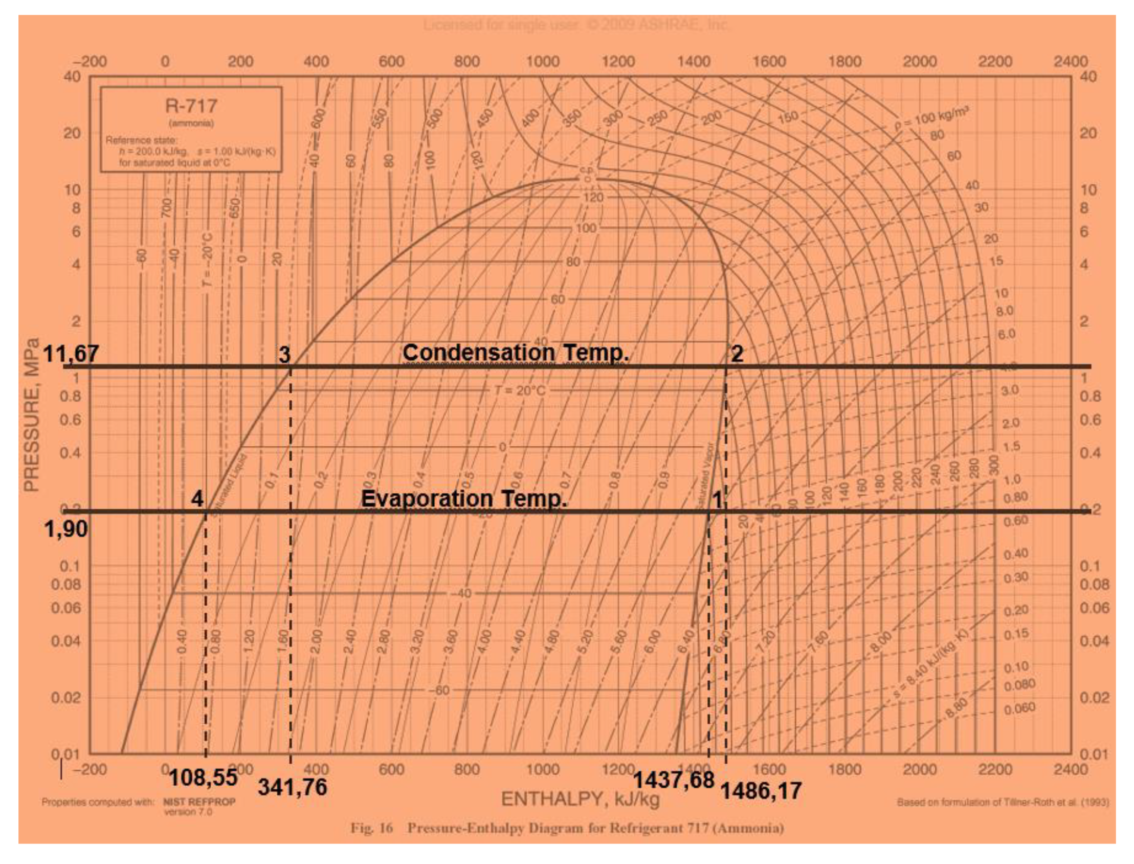
Figure 8.
Obtaining the evaporation and condensation temperature of the system by Mollier’s diagram.
Figure 8.
Obtaining the evaporation and condensation temperature of the system by Mollier’s diagram.

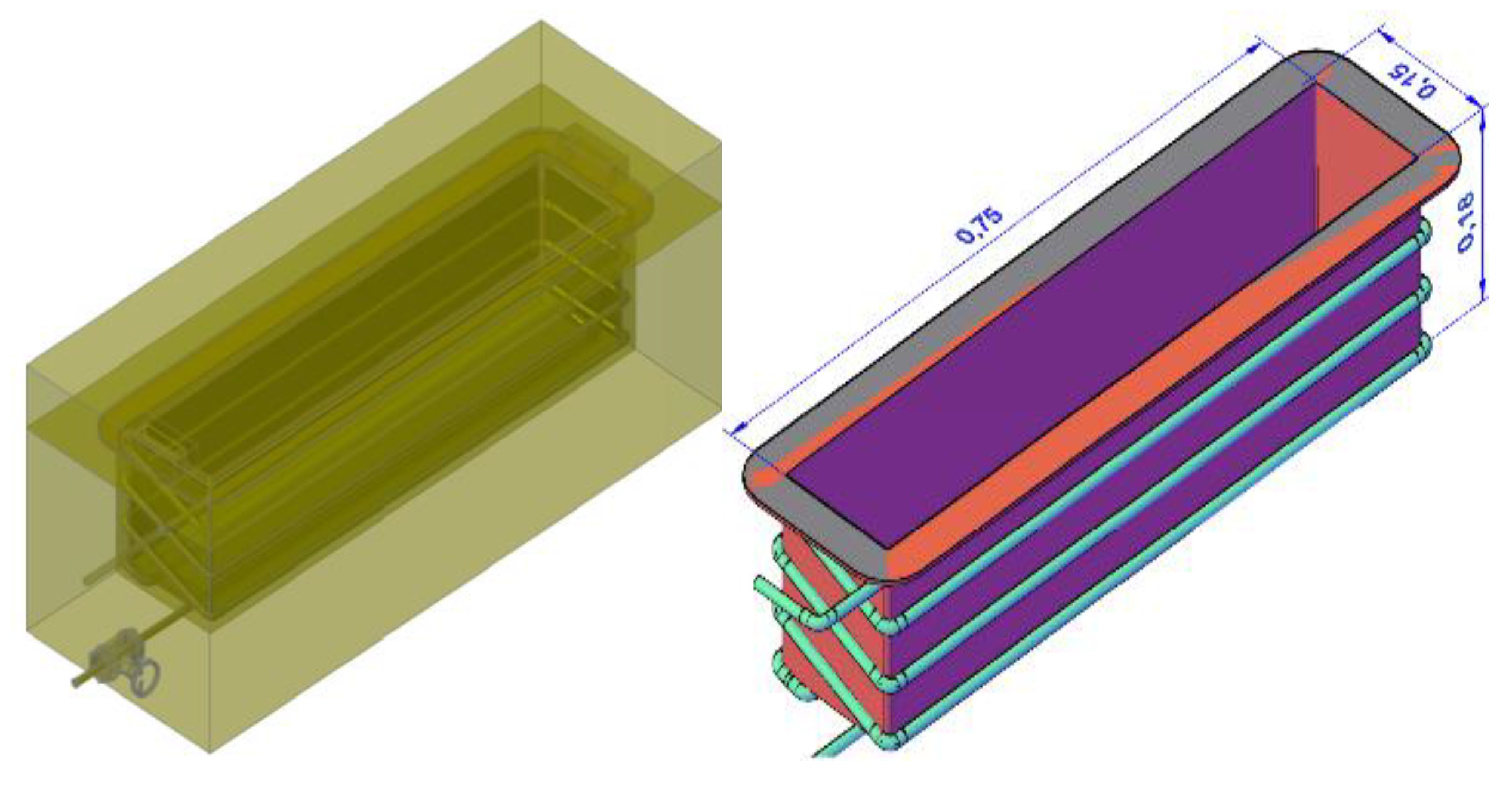
Figure 9.
Dimensions of the ice-box / evaporator.

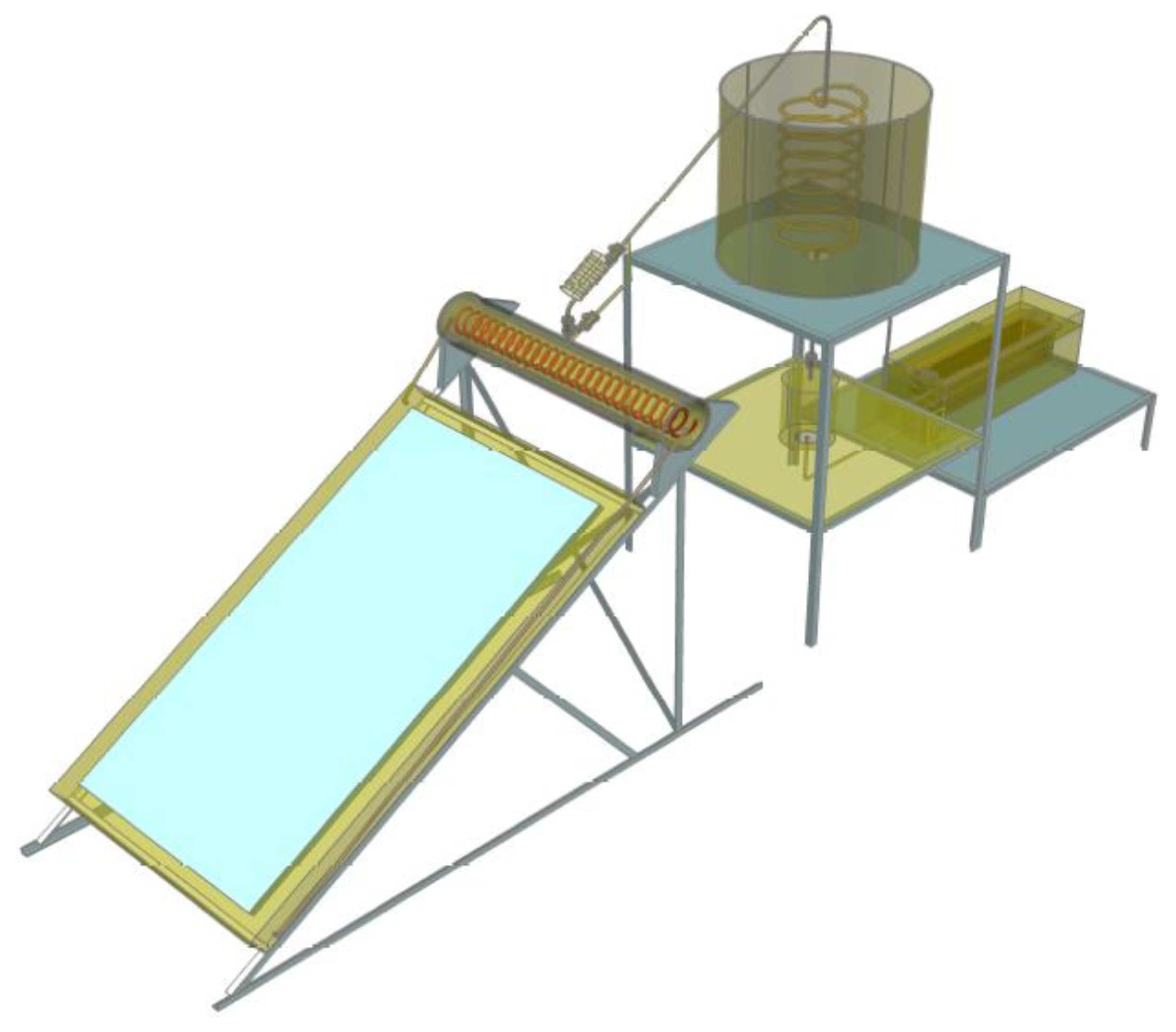
Figure 10.
Ice making machine.

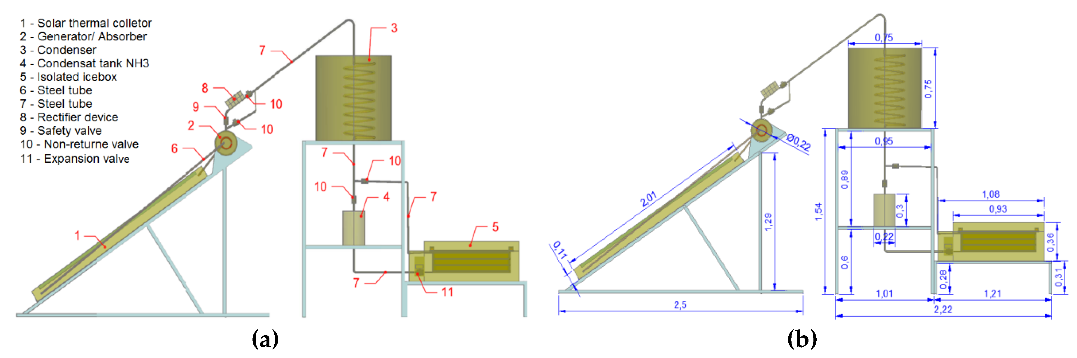
Figure 11.
Ice making machine—Side view—designation of components (a) and dimensioning (b).

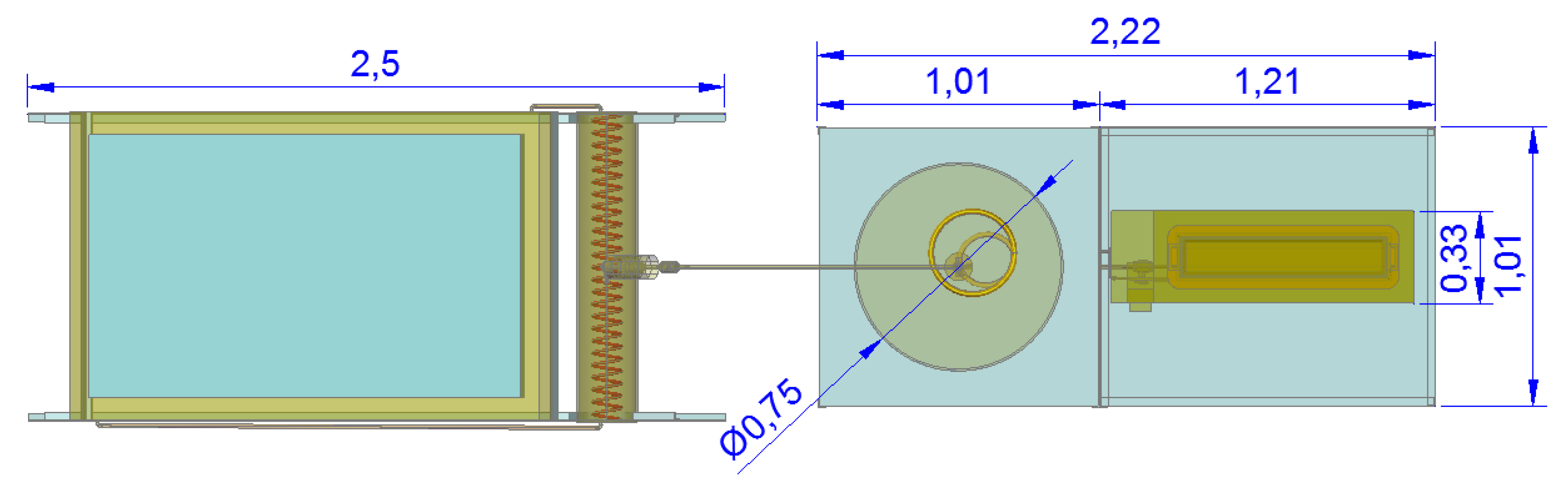
Figure 12.
Ice making machine—Plant and dimensioning.


Table 1.
Slopes used for collectors depending on the type of use.
| Use [Per Season] | Optimal Collector Slope/Inclination |
|---|---|
| Whole year [DHW] | Latitude – 5° |
| Winter [Heating] | Latitude + 15° |
| Summer [Outdoor pools/ hotels] | Latitude – 15° |
Table 2.
Cooling capacity (QFrig) for an operating period of 12 hours.
| Period of Operation | Mass Flow | QFrig | |
|---|---|---|---|
| [hours] | [seconds] | [kg/s] | [kW] |
| 12 | 43200 | 0.0003 | 0.132 |
Table 3.
Solar power—monthly energy needs and effective energy captured per months of the year.
| Solar Power and Monthly Energy Needs | Irradiation | Energy Captured Effective Monthly | ||||||
|---|---|---|---|---|---|---|---|---|
| Month | QFrig [W] | Solar power needed [W] | Monthly energy needs En.m [MJ] | Horizontal Irradiation monthly H (MJ/m2) | Useful hours of sun [h] | Real N°. Of collectors | CPC Collector Ecol.e [MJ] | Vacuum Tube Collector Ecol.e [MJ] |
| Jan | 122.65 | 245.31 | 328.52 | 8.10 | 8 | 1 | –154.60 | 175.67 |
| Feb | 124.59 | 249.18 | 301.41 | 10.90 | 9 | 1 | –103.87 | 224.62 |
| Mar | 125.07 | 250.15 | 335.00 | 14.60 | 9 | 1 | 7.79 | 355.58 |
| Apr | 126.29 | 252.57 | 327.33 | 19.40 | 9.5 | 1 | 112.39 | 451.80 |
| May | 129.31 | 258.62 | 346.35 | 24.10 | 9.5 | 1 | 245.96 | 573.75 |
| Jun | 130.52 | 261.04 | 338.31 | 26.00 | 9.5 | 1 | 306.38 | 606.05 |
| Jul | 132.34 | 264.67 | 354.45 | 27.70 | 9.5 | 1 | 426.91 | 715.12 |
| Aug | 132.22 | 264.43 | 354.13 | 25.00 | 9.5 | 1 | 403.07 | 693.79 |
| Sep | 131.01 | 262.01 | 339.57 | 18.80 | 9 | 1 | 262.18 | 544.82 |
| Oct | 128.58 | 257.17 | 344.40 | 13.10 | 9 | 1 | 67.03 | 391.02 |
| Nov | 125.56 | 251.12 | 325.45 | 9.20 | 8 | 1 | –52.72 | 249.30 |
| Dec | 123.74 | 247.49 | 331.43 | 7.40 | 7.5 | 1 | –131.41 | 176.21 |
Table 4.
Summary table of energy balances in the different components of the system.
| Designation | Evaporator | Absorber | Generator | Condenser |
|---|---|---|---|---|
| Equipment Temperature [°C] | –20 | 22 | 120 | 30 |
| Equipment Pressure [Bar] | 1.9 | 1.9 | 11.67 | 11.67 |
| Entrance Enthalpy [kJ/Kg] | 108.55 | 100 | 180 | 1486.17 |
| Exit Enthalpy [kJ/kg] | 1437.68 | –90 | 400 | 341.76 |
| Mass Flow [kg/s] | 1.0 × 10⁻⁴ | 1.0 × 10⁻⁴ | 1.6 × 10⁻⁴ | 1.6 × 10⁻⁴ |
| Refrigerating Power [W] | 132.34 | --- | --- | --- |
© 2019 by the authors. Licensee MDPI, Basel, Switzerland. This article is an open access article distributed under the terms and conditions of the Creative Commons Attribution (CC BY) license (http://creativecommons.org/licenses/by/4.0/).
Share and Cite
MDPI and ACS Style
Garcia, J.M.; Rosa, A. Theoretical Study of an Intermittent Water-Ammonia Absorption Solar System for Small Power Ice Production. Sustainability 2019, 11, 3346. https://doi.org/10.3390/su11123346
AMA Style
Garcia JM, Rosa A. Theoretical Study of an Intermittent Water-Ammonia Absorption Solar System for Small Power Ice Production. Sustainability. 2019; 11(12):3346. https://doi.org/10.3390/su11123346
Chicago/Turabian StyleGarcia, João M., and Armando Rosa. 2019. "Theoretical Study of an Intermittent Water-Ammonia Absorption Solar System for Small Power Ice Production" Sustainability 11, no. 12: 3346. https://doi.org/10.3390/su11123346
Note that from the first issue of 2016, this journal uses article numbers instead of page numbers. See further details here.