Article

Investigation of Various Active Layers for Their Performance on Organic Solar Cells

1
Institute of Microelectronics, Department of Electrical Engineering, National Cheng Kung University, Tainan 70101, Taiwan
2
Department of Applied Physics, National University of Kaohsiung, Nanzih, Kaohsiung 81148, Taiwan
*
Author to whom correspondence should be addressed.
Materials 2016, 9(8), 667; https://doi.org/10.3390/ma9080667
Submission received: 27 June 2016 / Revised: 29 July 2016 / Accepted: 1 August 2016 / Published: 9 August 2016
(This article belongs to the Special Issue Selected Papers from ICASI 2016)

Abstract

:
The theoretical mechanism of open-circuit voltages (VOC) in OSCs based on various small molecule organic materials is studied. The structure under investigation is simple planar heterojunction (PHJ) by thermal vacuum evaporation deposition. The various wide band gaps of small molecule organic materials are used to enhance the power conversion efficiency (PCE). The donor materials used in the device include: Alpha-sexithiophene (α-6T), Copper(II) phthalocyanine (CuPc), boron subnaphthalocyanine chloride (SubNc) and boron Subphthalocyanine chloride (SubPc). It is combined with fullerene or SubPc acceptor material to obtain a comprehensive understanding of the charge transport behavior. It is found that the VOC of the device is largely limited by charge transport. This was associated with the space charge effects and hole accumulation. These results are attributed to the improvement of surface roughness and work function after molybdenum trioxide (MoO3) is inserted as an anode buffer layer.

1. Introduction

A big milestone is being reached by organic solar cells (OSCs) because they have potential and are a conceivable alternative to traditional inorganic solar cells due to their ease of processing and compatibility with flexible substrates [1,2]. The OSCs have attracted significant industrial and academic interest and research as a promising source of renewable global energy today. At present, one of the most important issues is how to achieve the high power conversion efficiency (PCE) of solar cells through sample, solution and large area manufacturing methods. Following the introduction of the donor/acceptor (DA) interface by Tang, both the bulk heterojunction and tandem structure have been the most explored device architectures to enhance PCE [3,4,5]. The development of improved novel materials is another essential factor to further increase efficiency. The PCE of OSCs is improved continually by designing novel materials and device architectures for matching energy level in the active layer. One of the major challenges to obtaining high efficiency in OSCs is the low open-circuit voltage (VOC), which is restricted by the energy offset between the highest occupied molecule orbital (HOMO) of the electron donor and the lower unoccupied molecule orbital (LUMO) of the electron acceptor [6]. In 2010, Tang and co-workers published a study relating to Schottky barrier photovoltaic cells based on MoOX/C60 and realized a high VOC of 1.23 V with a simple bilayer structure of ITO/MoOX/C60/Bathophenanthroline (BPhen)/LiF/Al [7]. However, the PCE of the device is only about 0.5%. Finally, it was found that the Schottky barrier can provide DA heterojunction to dissociate the exciton to obtain more photocurrent and high Voc. On the other hand, fullerene molecules and their derivatives have become the primary acceptor materials in organic photovoltaic cells because of their better electron-accepting ability and high electron mobility [8,9]. The small absorption is due to overlap with the solar spectrum by using fullerene as an acceptor, which might be the reason that the photocurrent is limited. In addition, the small energy band gap also limits the VOC in the device [10].
In this study, we accomplished the bilayer device and measure the performance of Schottky barrier cell by replacing fullerene with SubPc or SubNc as the active layer through thermal vacuum evaporation deposition. We also examine a simple three-layer architecture comprising various organic materials as donor and acceptor, where an energy-relay cascade enables an efficient two-step exciton dissociation process. Figure 1 shows the chemical structure of the materials and a schematic diagram of the device structure. Finally, we obtained a short-circuit current (JSC) of 9.88 mA/cm2, a VOC of 0.94 V, and a PCE of 4.35% with the three-layer device structure: ITO-Glass/MoO3/α-6T/SubNc/SubPc/BCP/Ag.

2. Results

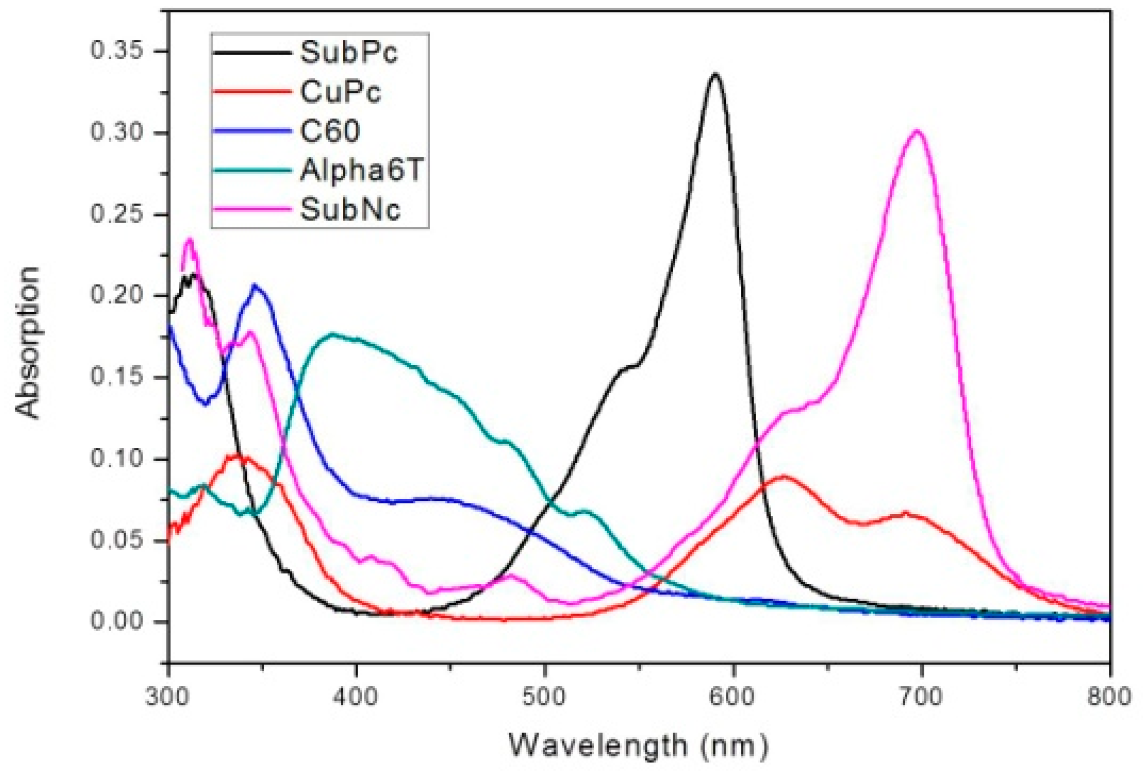
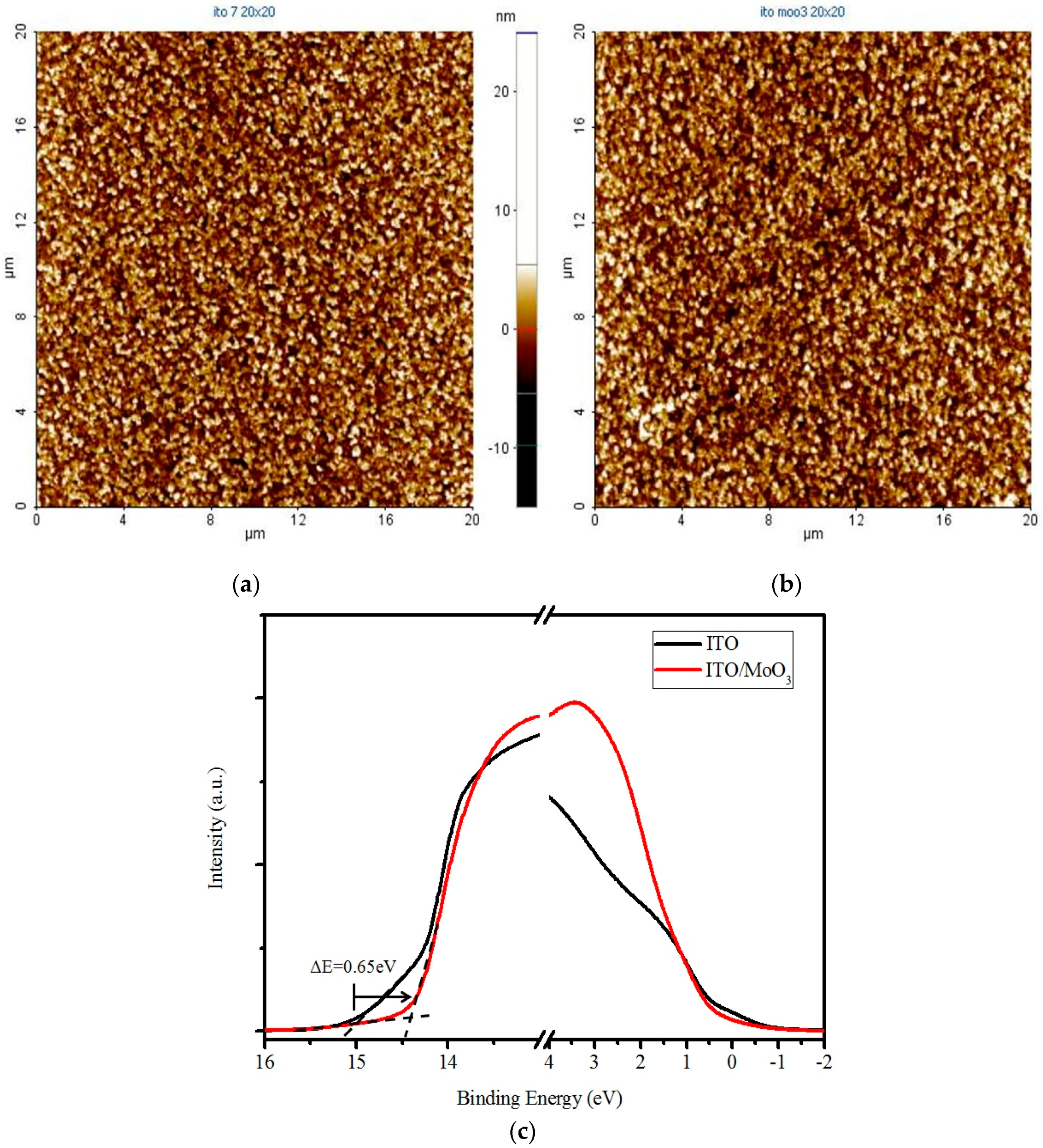
Bilayer devices were fabricated on indium tin oxide-coated glass substrates with sheet resistance of 7 Ω/sq. For the following layer structure: Molybdenum trioxide (MoO3)/Donor material/Fullerene (C60,C70)/Bathocuproine (BCP)/Ag, where the donor material is alpha-sexithiophene (α-6T), Copper(II) phthalocyanine (CuPc), boron subnaphthalocyanine chloride (SubNc) and boron Subphthalocyanine chloride (SubPc), Figure 2 shows the current density-voltage (J-V) characteristic of these device with various donor and acceptor materials. The energy levels of materials used are shown in the Figure 3. It explains the theoretical mechanism of VOC between donor and acceptor. Figure 4 shows the thin-film optical absorption spectrum of materials used from 300 nm to 800 nm. Figure 5 revealed the surface roughness with and without the anode buffer layer. The photovoltaic performance of bilayer OSCs (Donor/C60) are listed in the Table 1. Both Table 2 and Table 3 show the photovoltaic result based on α-6T donor material by using different acceptor material. Finally, the performance of three-layer cascade device based on following structure: ITO/MoO3/α-6T/SubNc/ SubPc/BCP/Ag is shown in Table 4.

3. Discussion

The thickness of the active layer was optimized to obtain an excellent PCE for each device. The thickness of the BCP cathode buffer layer and MoO3 anode buffer layer is fixed at 10 nm, respectively. In general, to get the better efficiency of OSCs, inserting the cathode buffer layer between the C60 and metal cathode is necessary. The electron transport across the cathode buffer layer mainly occurs via states induced in the cathode buffer layer during the cathode deposition. Most of the small molecular OSCs employ BCP or bathophenanthroline (Bphen) as a cathode buffer layer. In Figure 5a,b, the AFM measurements show the decreased roughness of ITO from 3.555 ± 0.045 to 2.735 ± 0.085 nm by covering the evaporated MoO3 layer. The AFM images simultaneously showed the difference from ITO and ITO/MoO3 in 2-dimensional (2D) top view to further understand the nanostructure. It is found that the roughness is improved by evaporating an MoO3 layer of 10 nm, although the ITO surface is not smooth because clear and dispersive white spots can be seen in Figure 5a. In other words, the dissociated exciton would fluently transport to an electrode when the MoO3 layer is deposited on the ITO surface, corresponding to the white spots gathering to become an island in the Figure 5b. On the other hand, it showed that the function of MoO3 not only acted as an exciton-blocking layer but also modified the work function of ITO [11,12,13]. In Figure 5c, the UPS spectrum showed the difference from ITO and ITO/MoO3. The work function of ITO was improved from 4.75 to 5.4 eV by using the MoO3 as a buffer layer. In the binding energy spectrum, the MoO3 deposited on ITO caused a 0.65 eV energy shift of secondary electron cutoff for lower binding energy, implying that the work function increased 0.65 eV by depositing an MoO3 layer on the ITO substrate. In the energy level diagram, the charge transport can be improved by depositing an MoO3 layer on the ITO substrate. Furthermore, light harvesting is another reason to obtain better performance, which is shown in Figure 3 and Figure 4. The LUMO energy level of C60 and C70 is −4.5 eV and −4.3 eV, and there was a closed HOMO energy level of −6.1 eV and −6.2 eV, respectively. The value of energy level difference between the HOMO energy level of the donor and LUMO energy level of the acceptor could be predicted in Figure 2. The structure of the CuPc/C60, SubPc/C60, α-6T/C60 and α-6T/C70 device is 0.7 eV, 1.1 eV, 0.7 eV and 0.5 eV, respectively. This reflects the VOC of the device from Table 1 to Table 3. The VOC of the SubPc/C60 device (0.5 V) is higher than that of the other devices, and it has a better efficiency of 1.3%, shown in Table 1. In out theorem, the maximal value of the VOC is associated with the energy level difference between the highest occupied molecular orbital of the donor (HOMOD) and the lowest unoccupied molecular orbital of the acceptor (LUMOA), but in fact the VOC of a device is determined according to the difference in the work function of the electrodes [14,15,16]. The HOMO and LUMO are not discrete energy levels, but are instead defined from a density of states with a disorder induced energy distribution, therefore suggesting that recombination losses mainly take place at the donor/acceptor interface. In other words, the work function improvement of ITO/MoO3 also enhances the built-in electric field of the device to increase the carrier collection. More detail about the investigation of VOC is related to the following equation:
V OC = 1 e ( LUMO A HOMO D Δ ) KT e ln ( n e n h N c 2 )
where the ne and nh are the electron and hole densities in the C60 and donor at open circuit; K is Boltzmann constant; Δ is the energy shift; T is the Kelvin scale and Nc is the density of conduction states at the band edge of C60 and donor (assume equal here). The commonly accepted value, VOC ≒ (LUMOA − HOMOD), is obtained from the above equation only at T = 0 K. The validity of the first term in equation has been verified for a number of 0.3 V of previously unknown origin [17,18,19]. At finite T, because of the fundamental statistics of Fermions, the quasi-Fermi levels move away from LUMOA and HOMOD, respectively, and into the gap above the polymer HOMO energy level and LUMO energy level. The resulting reduction in VOC is given by the second term in the equation and is the origin of the “missing 0.3 V” [17]. The efficiency of α-6T/C70 device is 1.44% which is better than that of other devices. This is attributed to the α-6T having excellent mobility and a broad absorption spectrum (As shown in the Figure 4). The absorption spectrum of BCP is below 350 nm, which is consistent with the BCP energy gap (3.5 eV). Furthermore, the approximate distribution of the absorption spectrum of another material is as follows: 300–400 nm and 600–700 nm for CuPc, 500–600 nm for SubPc, 350–550 nm for α-6T and 300–400 nm for C60. The small absorption overlap is the reason why the bilayer device based on the fullerene acceptor limited the efficiency and short-circuit density (JSC) performance.
Another method to increase the photocurrent in OSCs is incorporation of additional light-absorbing materials. Compared with the device based on fullerene in Table 1 and Table 2, both VOC and JSC are significantly improved for devices with SubPc and SubNc as an acceptor in Table 3. The device based on C60 acceptor in Table 1 achieved its best performance by using SubPc material with JSC of 4.37 mA/cm2, VOC of 0.55 V and PCE of 1.3%. The α-6T/C70 device in Table 2, however, has its best performance with JSC of 7.05 mA/cm2, VOC of 0.35 V and PCE of 1.44%. The SubNc/C70 device has its best performance with JSC of 7.15 mA/cm2, VOC of 0.68 V and PCE of 2.15%. The improvement of PCE from 1.44% to 2.15% is attributed to the increase of VOC from 0.5 eV for α-6T/C70 device to 0.9 eV for SubNc/C70 device. The non-fullerene concept has been established to further enhance the PCE of OSCs. We found that devices based on the α-6T as donor have excellent performance compared to fullerene-based cells by using different acceptor materials SubPc and SubNc. Both SubPc and SubNc have a LUMO energy level of −3.6 eV. It is obvious in Table 3 that the α-6T/SubPc device has better performance than the fullerene-based cells with JSC of 3.83 mA/cm2, VOC of 1.04 V and PCE of 2.56%. Both VOC and JSC are significantly improved for devices with SubPc or SubNc as acceptor, compared to the conventional device (CuPc/C60). Two mechanisms, two-step exciton dissociation and Förster resonance energy transfer (FRET), can explain the contribution from the SubNc and SubPc acceptor layer to the photocurrent. Seriously, the FRET mechanism is comprised within two-step exciton dissociation from SubPc to SubNc, and the consequent charge transfer at the α-6T/SubNc interface. According to dipole-dipole interactions, FRET is a long-range exciton transfer process occurring between luminescent energy donor and absorptive energy acceptor [20]. From emissive donor molecules to acceptor molecules, the Förster transfer was investigated and given by Scully et al. [21]. It is found that the calculation results of Förster transfer are approximate when we assume the thickness of middle layer is 0 nm between bilayer and the three-layer device. That is to say, the distance between dissociated exciton and quenching layer is approximate with the Förster radius of energy transfer (R0) of SubPc or SubNc as an acceptor. Investigation of energy transfer in organic photovoltaic cells and impact on exciton diffusion length measurement was also researched [22,23,24] (pp. 2977–2979, pp. 5–6, pp. 765–768). The R0 about the value of 7.5 nm and 6.0 nm, depending on the spectral overlap between the emission of the energy donor and absorption of the energy acceptor, was extracted for exciton energy transfer from SubPc and SubNc, respectively. Finally, we also fabricated the three-layer structure to increase the photocurrent generation for combining three different materials, α-6T/SubNc/SubPc. The thickness of both acceptor layers was adjusted to gain the maximum PCE again. The three-layer cascade device, forming an important alternative to traditional OSCs, has a higher performance with JSC of 9.88 mA/cm2, VOC of 0.94 V and PCE of 4.35%. It is similar to the bilayer device which has low FF results from increased thickness of the SubNc layer. Moreover, an increase of photocurrent generation is observed in the three-layer device structure, in which the VOC is similar to the bilayer device (α-6T/SubNc). Because of the approach of LUMO energy levels, the VOC does not decrease suddenly. This results in an impressive consequence from the bilayer to three-layer device, exceeding the current technology of vacuum-evaporated single junction of organic photovoltaic device. Through a simple process of vacuum thermal evaporation, we can reduce the cost of manufacturing the solar cells. As a result, the device with SubNc has become the interlayer to replace fullerene. Similar to an energy-relay cascade structure with multiple donor materials, both SubNc and SubPc can be combined as acceptors in a three-layer device structure. The generated excitons are transferred from SubPc acceptor to the middle SubNc layer and consequently dissociated at the α-6T/SubNc interface. To optimize the efficiency of OSCs, the interaction between the active layer and anode should be considered. That is to say the SubNc layer simultaneously has two functions: including an energy acceptor for excitons generated in the SubPc layer and as a charge acceptor at the interface with α-6T.

4. Materials and Methods

All organic materials were obtained through commercial source and were used without further sublimation in this study. The materials in the device were alpha-sexithiophene (α-6T, 99.0%-Aldrich), boron subphthalocyanine chloride (SubPc, 99.0%-Lumintech), (CuPc, 99.0%-Aldrich), fullerene (C60, C70 99.95%-Aldrich), and bathocuproine (BCP, 99.0%-Aldrich). The indium tin oxide-coated glass substrates (ITO-glass, with a sheet resistance of 7 Ω/sq) are sequentially cleaned through standard cleaning process of ultrasonic treatment in acetone, methanol, de-ionized (DI) water for 5 min each, and dried with nitrogen gas blow before deposition. The organic materials and Al (100 nm, as a cathode) were deposited by vacuum thermal evaporation below the pressure of 4.8 × 10⁻⁶ torr. The deposition rate of organic materials was at 0.03 ± 0.01 nm/s, and the cathode was deposited through a shadow mask, giving an active area of 6 mm2 at a deposition rate of 0.3 ± 0.03 nm/s. Deposition rate and film thickness were monitored by using quartz crystal oscillator. The current density-voltage (J-V) characteristics were measured with a power source meter (Keithley 2400, Keithley, Cleveland, AL, USA) under an illumination of 100 mW/cm2 with an AM1.5G sun simulator (Oriel 96000 150W Xe lamp, Newport, Taipei, Taiwan). The light intensity was calibrated by using a reference solar cell and meter (Oriel 91150, Newport, Taipei, Taiwan), and all measurements were carried out in air with encapsulation.
Investigations of microstructure and sheet resistance (Rs) were carried out using X-ray diffraction (XRD, Rigaku/Ultima, Tokyo, Japan) and four point sheet resistivity (SRM103, Solar Energy Tech Ins, Suzhou, China), respectively. The work function of ITO was measured by using ultraviolet photoelectron spectroscopy (UPS, Sigma Probe, Thermo VG-Scientific, Waltham, MA, USA) with monochromatized He (21.2 eV) discharge lamp. The spectrum was taken for −5 V sample bias to separate the sample and the secondary edge for the analyzer. Devices were further measured by atomic force microscope (AFM, XE-70, Park Systems, Suwon, Korea) to analyze the surface morphology with 0.5 Hz scan rate probing an area of 20 × 20 μm2, which effectively reducing the speed at which the tip moves and allowing the system more time to adjust to sudden changes in height, and by spectrophotometer (UV-3900, Hitachi, Tokyo, Japan) to gauge the absorption spectrum of device. All measurements were carried out in air with encapsulation.

5. Conclusions

We have demonstrated that the simple three-layer architecture plays an important role in enhancing the PCE of OSCs by using various small molecule organic materials. The thin-film optical absorption spectrum is broadened theoretically for the entire spectrum of solar energy when the device comprising two non-fullerene acceptors and a donor was accomplished. We also accomplished the bilayer OSCs to understand the device performance with and without fullerene materials as acceptor. Both the surface roughness and work function are improved by inserting MoO3 anode buffer layer between the ITO and donor, at the same time, to explain the improved PCE and strengthened ability of the charge transportation. The VOC of devices based on α-6T, SubNc, SubPc and CuPc as donor can be largely advanced by depositing MoO3 layer on ITO substrate, which results from less carrier recombination in the active layer and the improvement of work function in the anode. According to the two-step exciton-dissociating mechanism, both SubPc and SubNc can be combined as acceptors in the three-layer device structure by utilizing long-range FRET. The generated excitons are transferred from SubPc acceptor to the middle SubNc layer and consequently dissociated at the α-6T/SubNc interface. To optimize the efficiency of OSCs, the interaction between the active layer and anode should be considered. That is to say the SubNc layer simultaneously has two functions, including an energy acceptor for excitons generated in the SubPc layer and as a charge acceptor at the interface with a-6T.

Acknowledgments

This work was partially supported by the National Science Council of the Republic of China under Contract No. NSC 104-2221-E-390-016.

Author Contributions

Pao-Hsun Huang, Yeong-Her Wang, Jhong-Ciao Ke and Chien-Jung Huang analyzed the materials; Pao-Hsun Huang, Jhong-Ciao Ke and Chien-Jung Huang conceived and designed the experiments; Pao-Hsun Huang performed the experiments; Pao-Hsun Huang, Yeong-Her Wang, Jhong-Ciao Ke and Chien-Jung Huang analyzed the data; Yeong-Her Wang and Chien-Jung Huang contributed analysis tools; Pao-Hsun Huang wrote the paper.

Conflicts of Interest

The authors declare no conflict of interest.

References

  1. Forrest, S.R. The path to ubiquitous and low-cost organic electronic applianceson plastic. Nature 2004, 428, 911–918. [Google Scholar] [CrossRef] [PubMed]
  2. Service, R.F. Outlook brightens for plastic solar cells. Science 2011, 332, 293. [Google Scholar] [CrossRef] [PubMed]
  3. Tang, C.W. Two-layer organic photovoltaic cell. Appl. Phys. Lett. 1986, 48, 183–185. [Google Scholar] [CrossRef]
  4. Cheyns, D.; Rand, B.P.; Heremans, P. Organic tandem solar cells with complementary absorbing layers and a high open-circuit voltage. Appl. Phys. Lett. 2010, 97. [Google Scholar] [CrossRef]
  5. You, J.; Dou, L.D.; Yoshimura, K.; Kato, T.; Ohya, K.; Moriarty, T.; Emery, K.; Chen, C.C.; Gao, J.; Li, G.; et al. A polymer tandem solar cell with 10.6% power conversion efficiency. Nat. Commun. 2013, 4. [Google Scholar] [CrossRef] [PubMed]
  6. Chen, L.M.; Xu, Z.; Hong, Z.; Yang, Y. Interface investigation and engineering—Achieving high performance polymer photovoltaicdevices. J. Mater. Chem. 2010, 20, 2575–2598. [Google Scholar] [CrossRef]
  7. Zhang, M.; Irfan, I.M.; Ding, H.; Gao, Y.; Tang, C.W. Organic Schottky barrier photovoltaic cells based on MoOx/C60. Appl. Phys. Lett. 2010, 96. [Google Scholar] [CrossRef]
  8. Li, C.Z.; Yip, H.L.; Jen, A.K.Y. Functional fullerenes for organic photovoltaics. J. Mater. Chem. 2012, 22, 4161–4177. [Google Scholar] [CrossRef]
  9. He, Y.; Li, Y. Fullerene derivative acceptors for high performance polymer solar cells. Phys. Chem. Chem. Phys. 2011, 13, 1970–1983. [Google Scholar] [CrossRef] [PubMed]
  10. Hoke, E.T.; Vandewal, K.; Bartelt, J.A.; Mateker, W.R.; Douglas, J.D.; Noriega, R.; Graham, K.R.; Fréchet, J.M.J.; Salleo, A.; McGehee, M.D. Recombination in polymer:fullerene solar cells with open-circuit voltages approaching and exceeding 1.0 v. Adv. Energy Mater. 2012, 3, 220–230. [Google Scholar] [CrossRef]
  11. Gommans, H.; Aernouts, T.; Verreet, B.; Heremans, P.; Medina, A.; Claessens, C.G.; Torres, T. Perfluorinated subphthalocyanine as a new acceptor material in a small-molecule bilayer organic solar cell. Adv. Funct. Mater. 2009, 19, 3435–3439. [Google Scholar] [CrossRef]
  12. Verreet, B.; Rand, B.P.; Cheyns, D.; Hadipour, A.; Aernouts, T.; Heremans, P.; Medina, A.; Claessens, C.G.; Torres, T. A 4% efficient organic solar cell using a fluorinated fused subphthalocyanine dimer as an electron acceptor. Adv. Energy Mater. 2011, 1, 565–568. [Google Scholar] [CrossRef]
  13. Sullivan, P.; Durand, A.; Hancox, I.; Beaumot, N.; Mirri, G.; Tucker, J.H.R.; Hatton, R.A.; Shipman, M.; Jones, T.S. Halogenated boron subphthalocyanines as light harvesting electron acceptors in organic photovoltaics. Adv. Energy Mater. 2011, 1, 352–355. [Google Scholar] [CrossRef]
  14. Huang, C.J.; Ke, J.C.; Chen, W.R.; Meen, T.H.; Yang, C.F. Improved the efficiency of small molecule organic solar cell by double anode buffer layers. Sol. Energy Mater. Sol. 2011, 95, 3460–3464. [Google Scholar] [CrossRef]
  15. Ke, J.C.; Wang, Y.H.; Chen, K.L.; Huang, C.J. Effect of organic solar cells using various sheet resistances of indium tin oxide and different cathodes: Aluminum, silver. Synth. Met. 2015, 201, 25–29. [Google Scholar] [CrossRef]
  16. Ke, J.C.; Wang, Y.H.; Chen, K.L.; Huang, C.J. Effect of open-circuit voltage in organic solar cells based on various electron donor materials by inserting molybdenum trioxide anode buffer layer. Sol. Energy Mater. Sol. 2015, 133, 248–254. [Google Scholar] [CrossRef]
  17. Brabec, C.J.; Cravino, A.; Meissner, D.; Sariciftci, N.S.; Fromherz, T.; Rispens, M.T.; Sanchez, L.; Hummelen, J.C. Origin of the open circuit voltage of plastic solar cells. Adv. Funct. Mater. 2001, 11, 374–380. [Google Scholar] [CrossRef]
  18. Spano, F.C. Modeling disorder in polymer aggregates: The optical spectroscopy of regioregular poly(3-hexylthiophene) thin films. J. Chem. Phys. 2005, 122. [Google Scholar] [CrossRef] [PubMed]
  19. Garcia-Belmonte, G.; Bisquert, J. Open-circuit voltage limit caused by recombination through tail states in bulk heterojunction polymer-fullerene solar cells. Appl. Phys. Lett. 2010, 96. [Google Scholar] [CrossRef]
  20. Förster, T. 10th Spiers Memorial Lecture. Transfer mechanisms of electronic excitation. Discuss. Faraday Soc. 1959, 27, 7–17. [Google Scholar] [CrossRef]
  21. Scully, S.R.; Armstrong, P.B.; Edder, C.; Fre’chet, J.M.J.; McGehee, M.D. Long-range resonant energy transfer for enhanced exciton harvesting for organic solar cells. Adv. Mater. 2007, 19, 2961–2966. [Google Scholar] [CrossRef]
  22. Gommans, H.; Schols, S.; Kadashchuk, A.; Heremans, P. Exciton diffusion length and lifetime in subphthalocyanine films. J. Phys. Chem. C 2009, 113, 2974–2979. [Google Scholar] [CrossRef]
  23. Lunt, R.R.; Giebink, N.C.; Belak, A.A.; Benziger, J.B.; Forrest, S.R. Exciton diffusion lengths of organic semiconductor thin films measured by spectrally resolved photoluminescence quenching. J. Appl. Phys. 2009, 105. [Google Scholar] [CrossRef]
  24. Luhman, W.A.; Holmes, R.J. Investigation of energy transfer in organic photovoltaic cells and impact on exciton diffusion length measurements. Adv. Funct. Mater. 2011, 21, 764–771. [Google Scholar] [CrossRef]
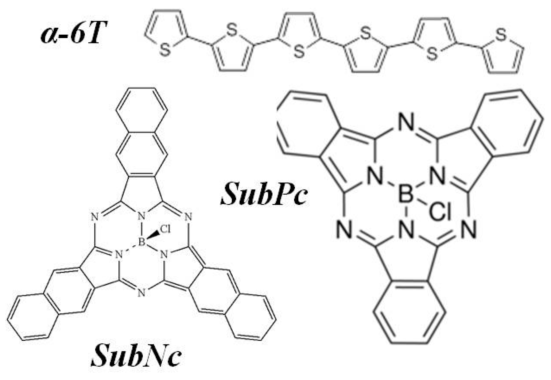
Figure 1. The molecule chemical structure of the used materials and schematic representation of the device structure.
Materials 09 00667 g001
Figure 2. The current density-voltage (J-V) characteristic of these devices with various donor and acceptor materials.
Materials 09 00667 g002
Figure 3. The energy levels diagram of used materials illustrating the charge transfer mechanism in this study.
Materials 09 00667 g003
Figure 4. The thin-film optical absorption spectrum of used materials from 300 nm to 800 nm to effectively harvest the solar light.
Materials 09 00667 g004
Figure 5. The result of surface roughness: (a) The device with the anode buffer layer; (b) The device without the anode buffer layer; (c) The ultraviolet photoelectron spectroscopy (UPS) spectrum of indium tin oxide (ITO) and ITO/MoO3.
Materials 09 00667 g005
Table 1. The photovoltaic performance of bilayer organic solar cells (OSCs) (Donor/C60) is sorted and estimated the properties of devices with structure: ITO/MoO3 (10 nm)/Donor/C60 (30 nm)/Bathocuproine (BCP) (10 nm)/Ag (100 nm).
Material Thickness (nm)JSC (mA/cm2)VOC (V)FF (%)η (%)RS (Ω)RSh (kΩ)
SubPc4.57 ± 0.021.00 ± 0.0155.27 ± 1.222.52 ± 0.1031.711.125
9
CuPc3.41 ± 0.050.39 ± 0.0254.00 ± 1.310.70 ± 0.0823.630.96
20
α-6T3.67 ± 0.080.35 ± 0.0255.30 ± 1.170.71 ± 0.0523.530.96
40
Table 2. The photovoltaic performance of bilayer OSCs (α-6T/Acceptor) is sorted and estimated the properties of devices with MoO3 (10 nm), BCP (10 nm), and Ag (100 nm).
Material Thickness (nm)JSC (mA/cm2)VOC (V)FF (%)η (%)RS (Ω)RSh (kΩ)
α-6TITO/MoO3/α-6T (X nm)/C70 (30 nm)/BCP/Ag
406.01 ± 0.070.36 ± 0.0256.56 ± 1.021.23 ± 0.1012.550.386
505.98 ± 0.020.38 ± 0.0256.37 ± 1.041.28 ± 0.0912.790.49
605.92 ± 0.050.39 ± 0.0153.57 ± 1.421.24 ± 0.0715.460.501
C70ITO/MoO3/α-6T (40 nm)/C70 (X nm)/BCP/Ag
206.35 ± 0.050.34 ± 0.0158.30 ± 0.021.26 ± 0.049.770.563
257.05 ± 0.050.35 ± 0.0258.28 ± 0.031.44 ± 0.099.470.454
306.26 ± 0.020.35 ± 0.0257.66 ± 0.071.26 ± 0.0811.230.517
326.03 ± 0.070.33 ± 0.0157.01 ± 0.111.14 ± 0.0410.310.416
SubNcITO/MoO3/SubNc (X nm)/C70 (30 nm)/BCP/Ag
107.15 ± 0.130.68 ± 0.0244.12 ± 1.852.15 ± 0.1924.950.311
406.73 ± 0.110.72 ± 0.0129.71 ± 1.771.44 ± 0.1382.810.178
504.58 ± 0.180.70 ± 0.0225.11 ± 1.820.81 ± 0.11123.320.184
Table 3. The photovoltaic performance of bilayer OSCs (α-6T/Acceptor) is sorted and estimated the properties of devices with MoO3 (10 nm), BCP (10 nm), and Ag (100 nm).
Material Thickness (nm)JSC (mA/cm2)VOC (V)FF (%)η (%)RS (Ω)RSh (kΩ)
SubPcITO/MoO3/α-6T (50 nm)/SubPc (X nm)/BCP/Ag
96.01 ± 0.030.36 ± 0.0356.56 ± 0.041.23 ± 0.1012.550.386
55.98 ± 0.020.38 ± 0.0156.37 ± 0.071.28 ± 0.0412.790.49
185.92 ± 0.060.39 ± 0.0253.57 ± 1.011.24 ± 0.1015.460.501
α-6TITO/MoO3/α-6T (X nm)/SubPc (18 nm)/BCP/Ag
504.14 ± 0.070.87 ± 0.0350.70 ± 1.721.83 ± 0.1353.641.45
603.83 ± 0.071.04 ± 0.0364.14 ± 1.982.56 ± 0.2117.242.689
SubNcITO/MoO3/α-6T (60 nm)/SubNc (X nm)/BCP/Ag
125.75 ± 0.340.73 ± 0.0451.66 ± 1.422.17 ± 0.3264.860.608
165.68 ± 0.260.61 ± 0.0551.79 ± 1.581.80 ± 0.2912.460.481
Table 4. The photovoltaic performance of three-layer OSCs (α-6T/SubNc/SubPc) is sorted and estimated the properties of devices with MoO3 (10 nm), SubPc (18 nm), BCP (10 nm), and Ag (100 nm).
SubNc Thickness (nm)JSC (mA/cm2)VOC (V)FF (%)η (%)RS (Ω)RSh (kΩ)
03.83 ± 0.051.04 ± 0.0264.14 ± 1.552.56 ± 0.1417.242.689
37.19 ± 0.020.96 ± 0.0243.61 ± 1.243.01 ± 0.1625.940.878
68.28 ± 0.010.93 ± 0.0345.20 ± 1.313.48 ± 0.1219.290.576
1210.12 ± 0.060.94 ± 0.0144.12 ± 1.484.20 ± 0.1917.410.449
159.88 ± 0.010.94 ± 0.0246.81 ± 1.174.35 ± 0.2012.950.443
186.14 ± 0.030.93 ± 0.0248.65 ± 1.062.78 ± 0.1320.480.615