
Effects of Plasma ZrN Metallurgy and Shot Peening Duplex Treatment on Fretting Wear and Fretting Fatigue Behavior of Ti6Al4V Alloy

Abstract
:1. Introduction
2. Materials and Methods
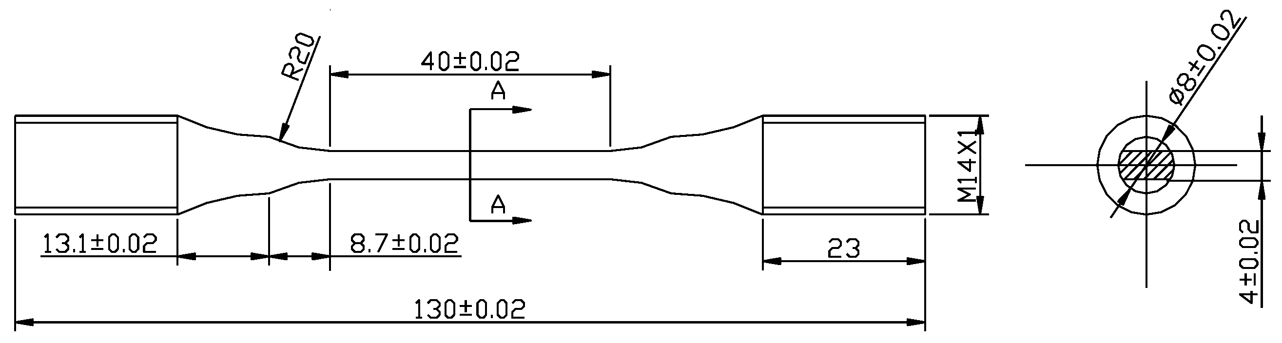
2.1. Materials and Samples
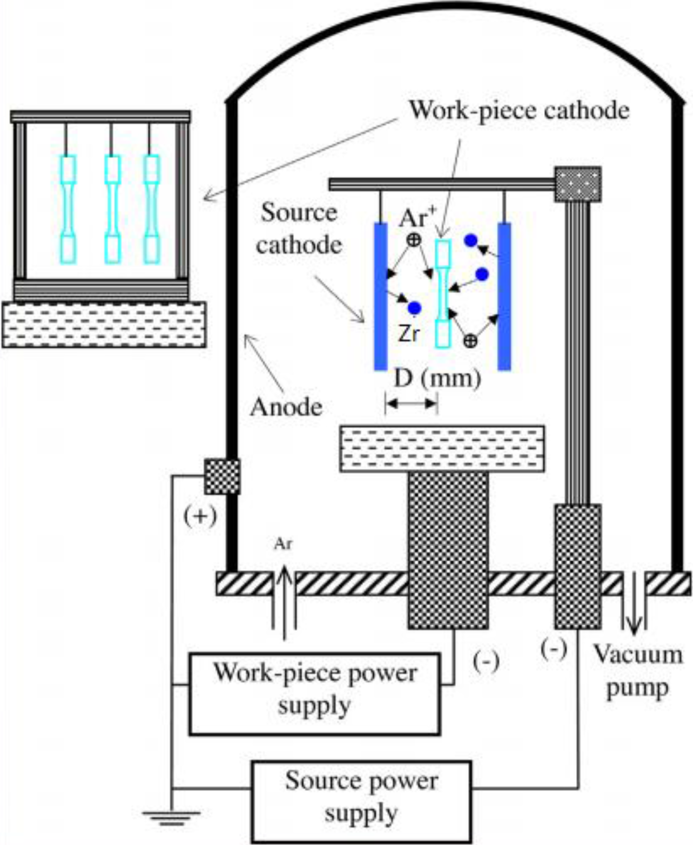
2.2. Surface Modification Treatments
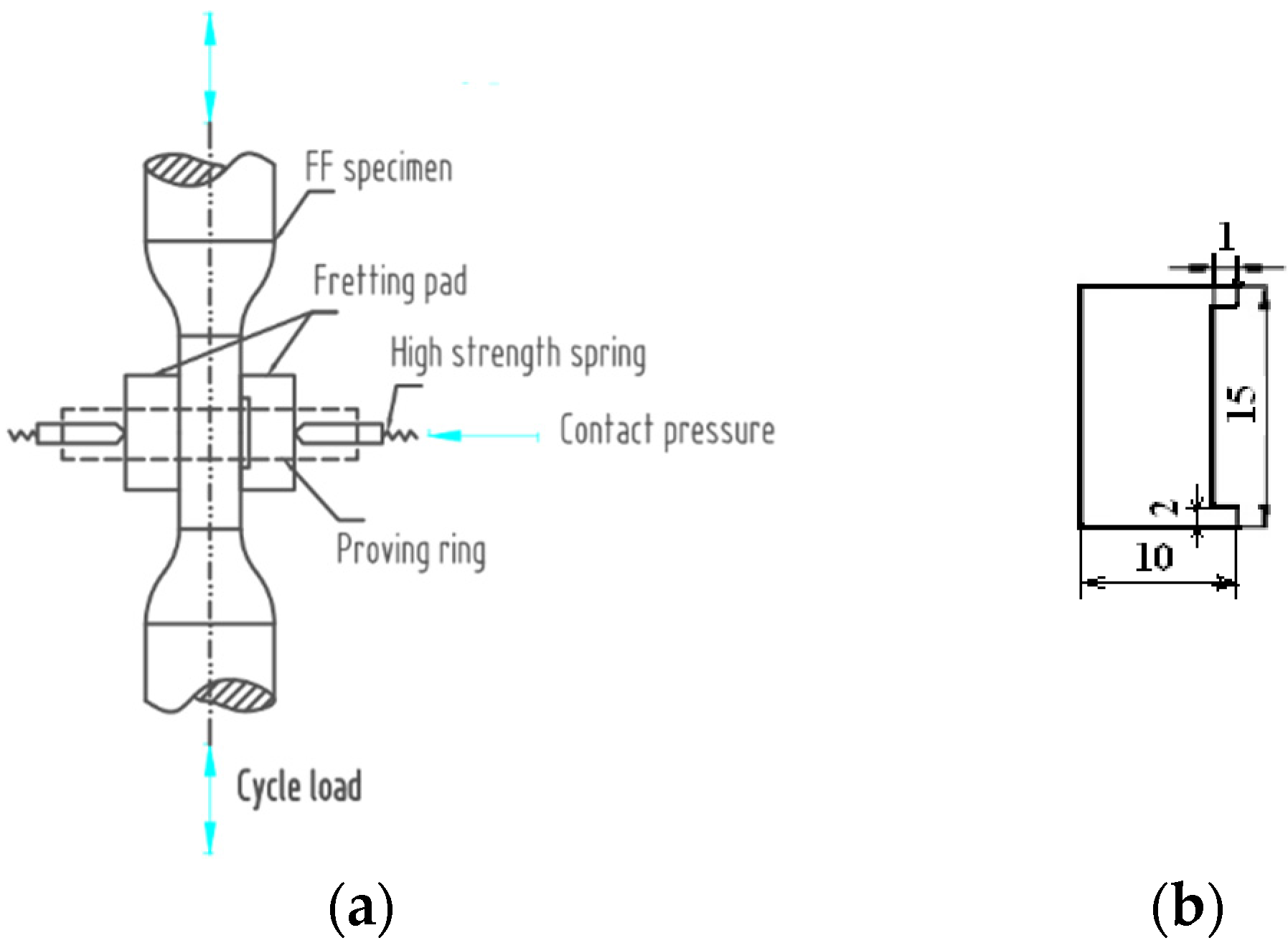
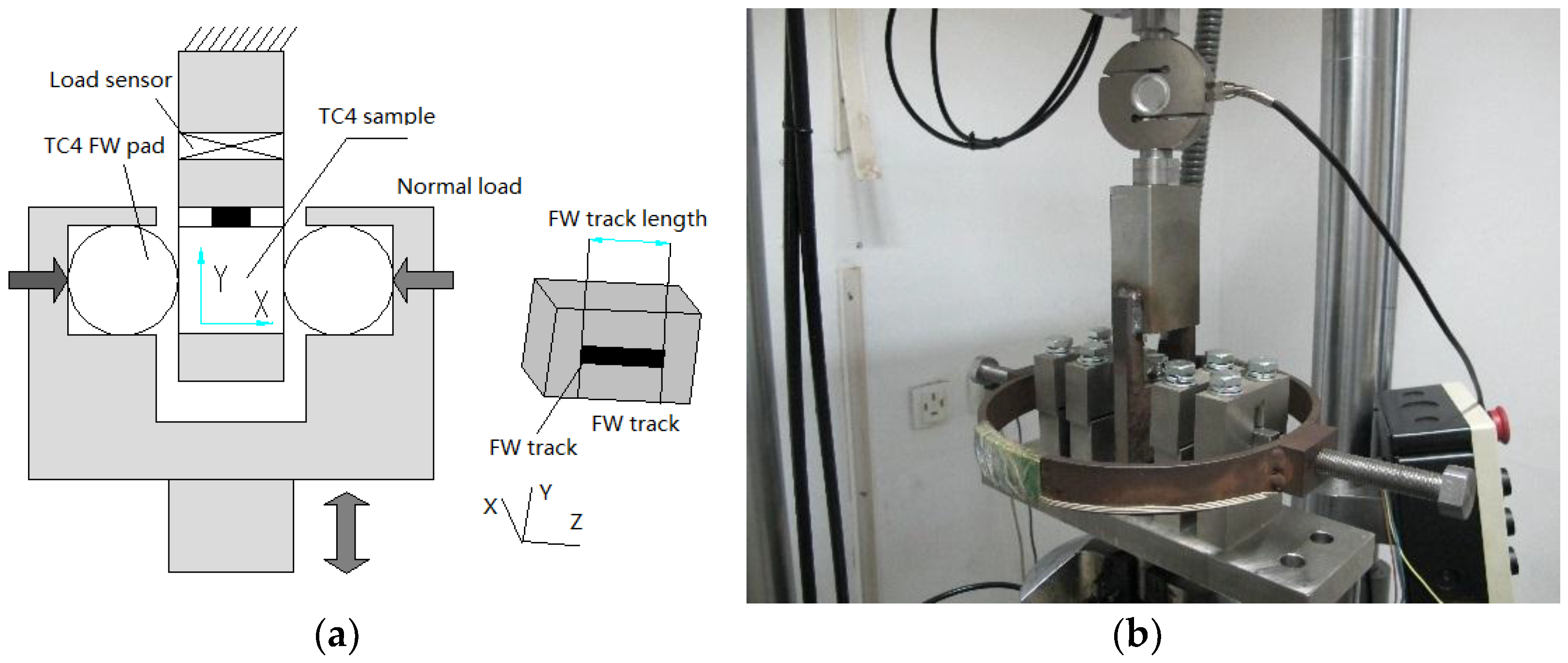
2.3. FW Experiment and FF Experiments
2.4. Analysis and Measuring Method
3. Results
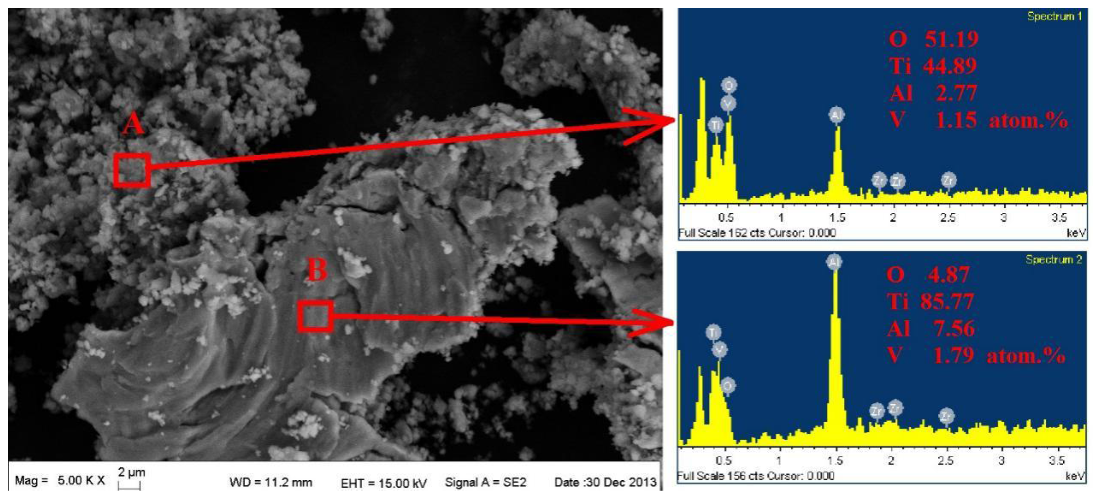
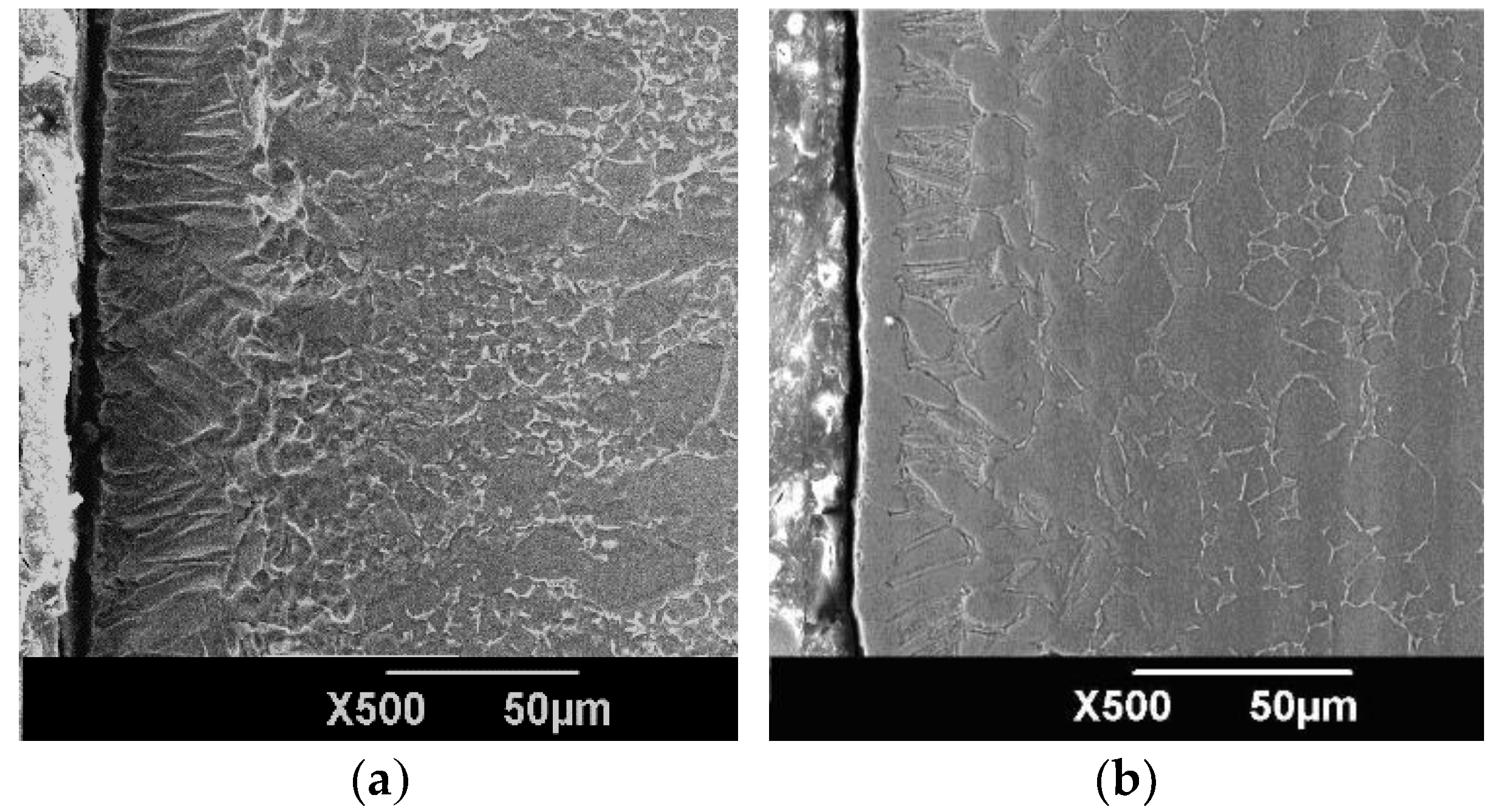
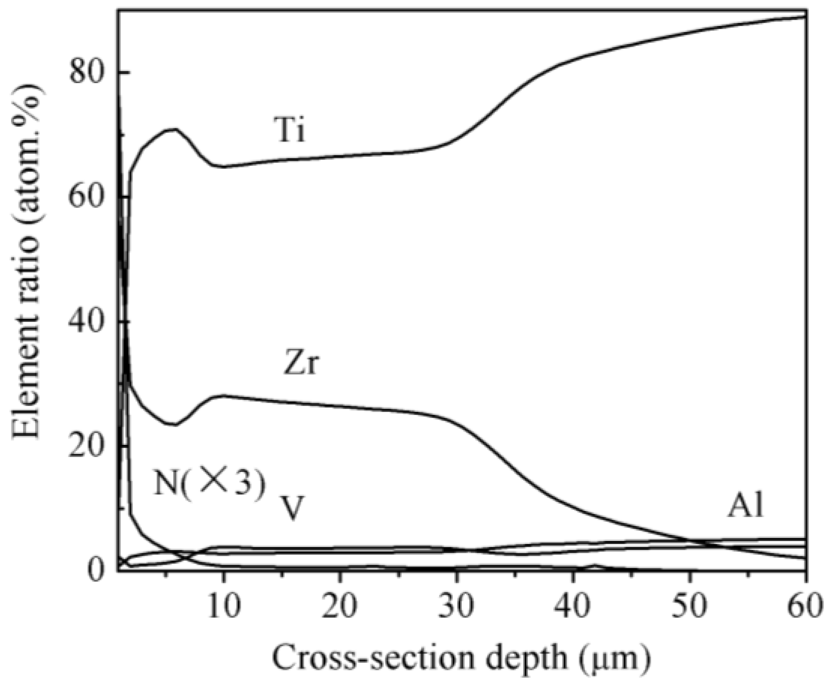
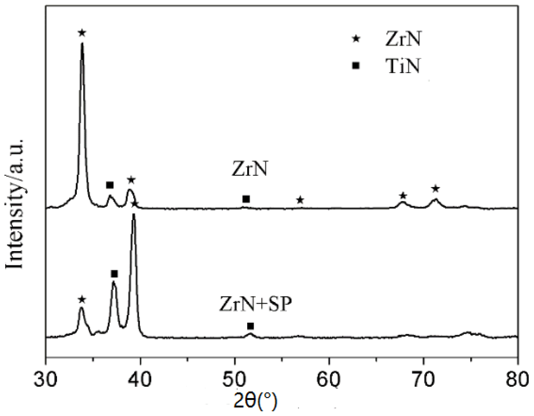
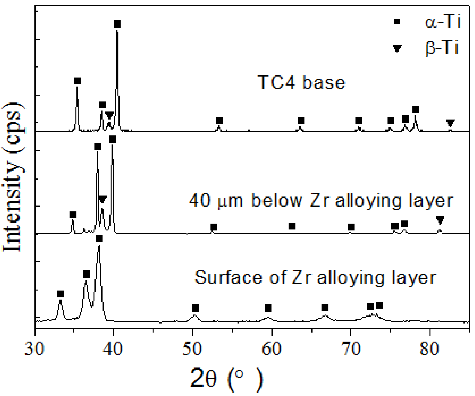
3.1. Microstructure and Cross-Sectional Composition
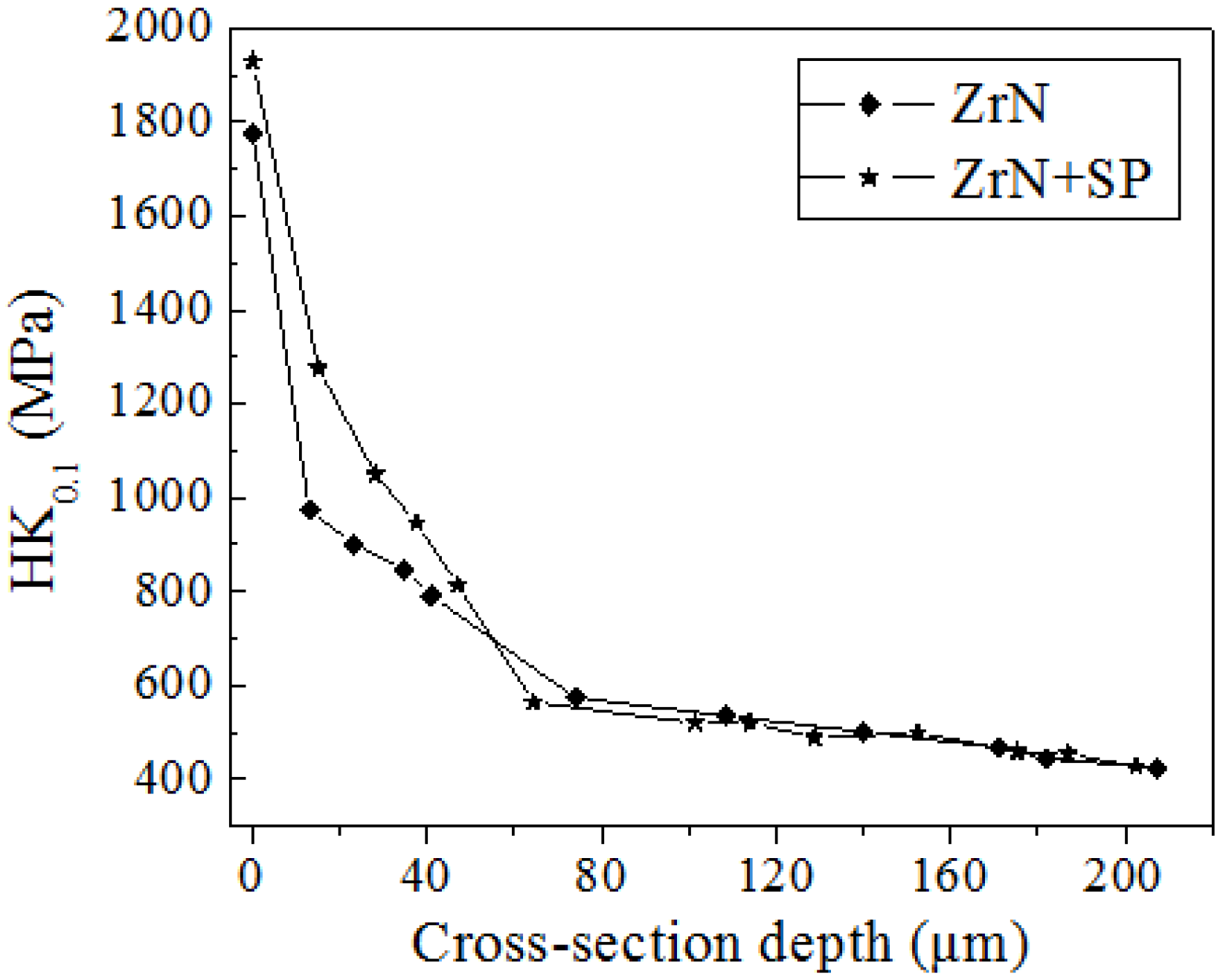
3.2. Cross-Sectional Microhardness Distribution
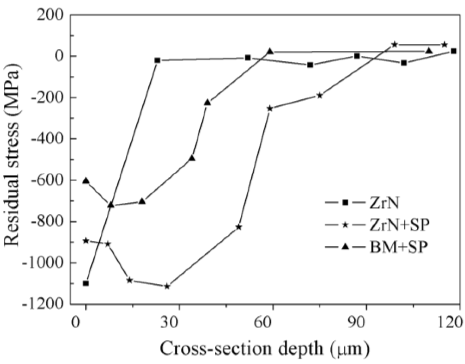
3.3. Compressive Residual Stress Distribution with Depth
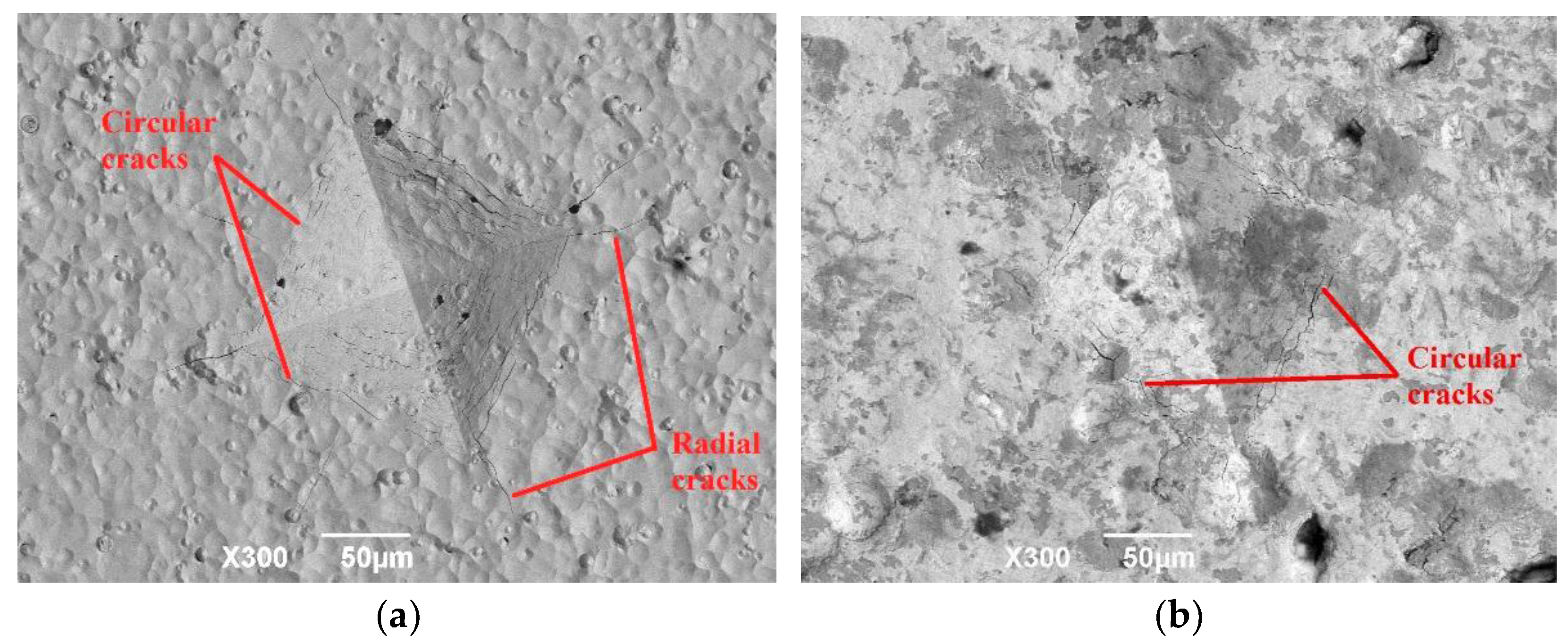
3.4. Ductility of Modification Layer
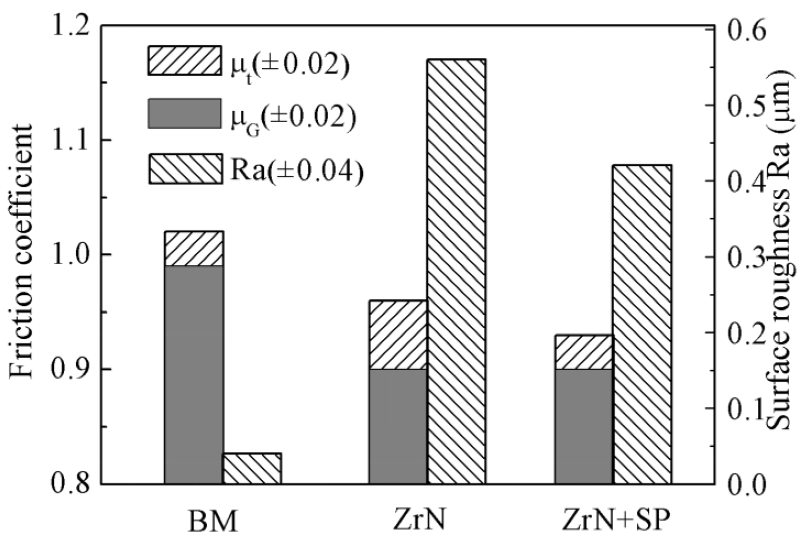
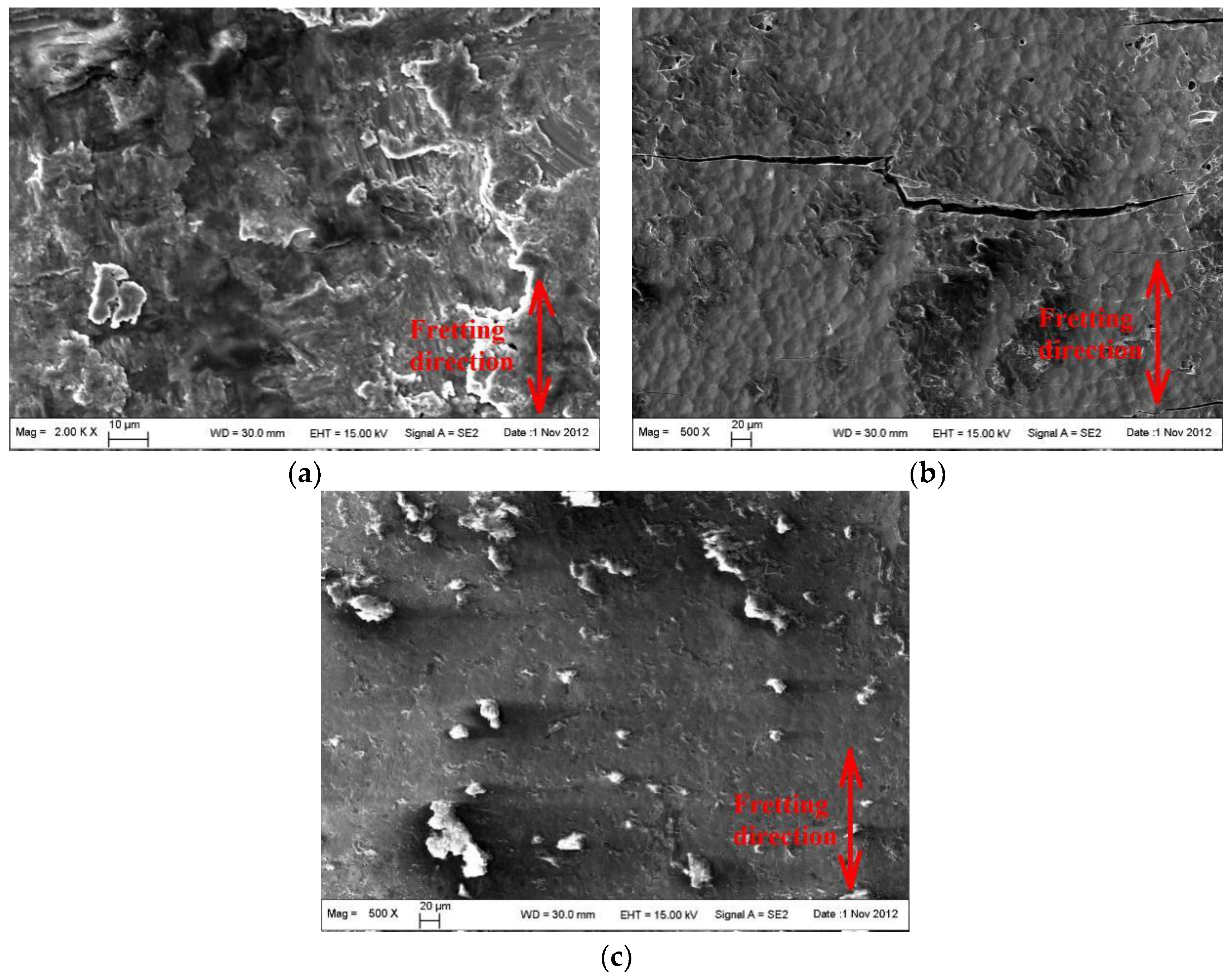
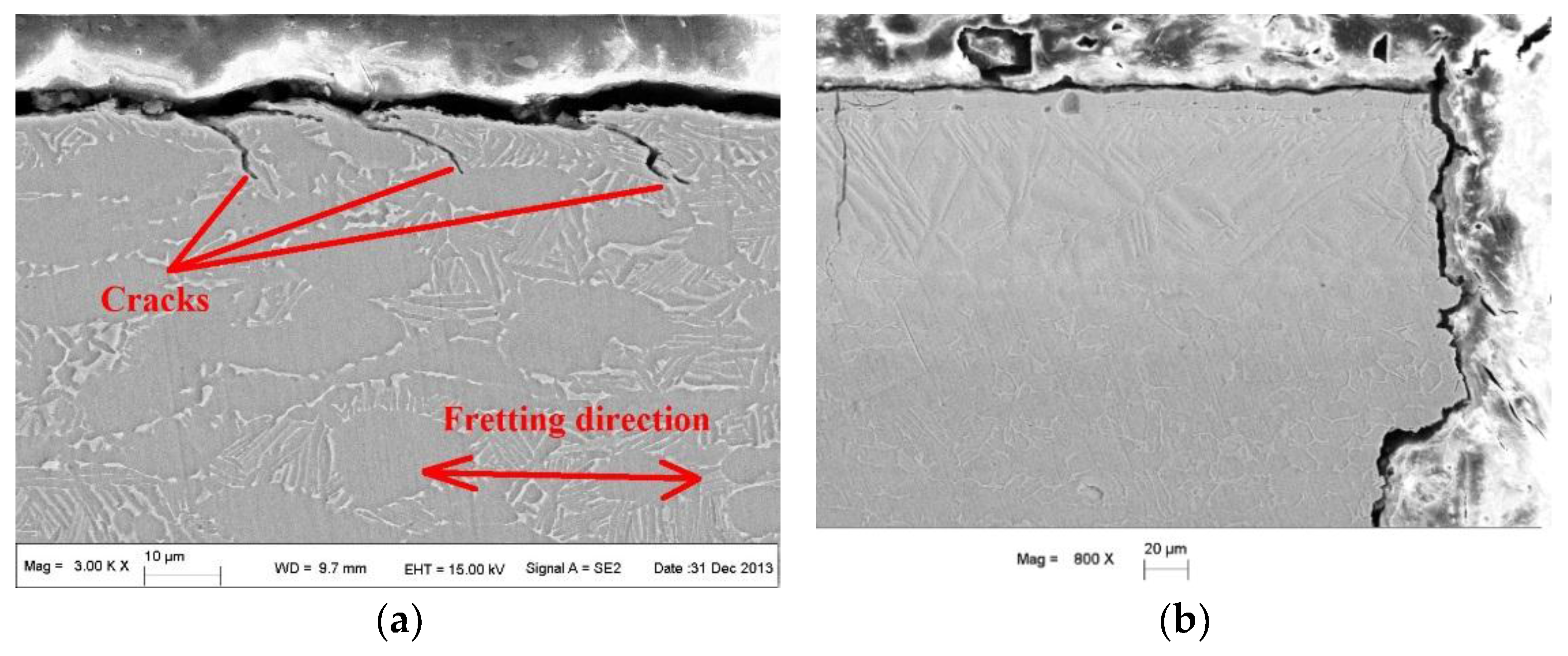
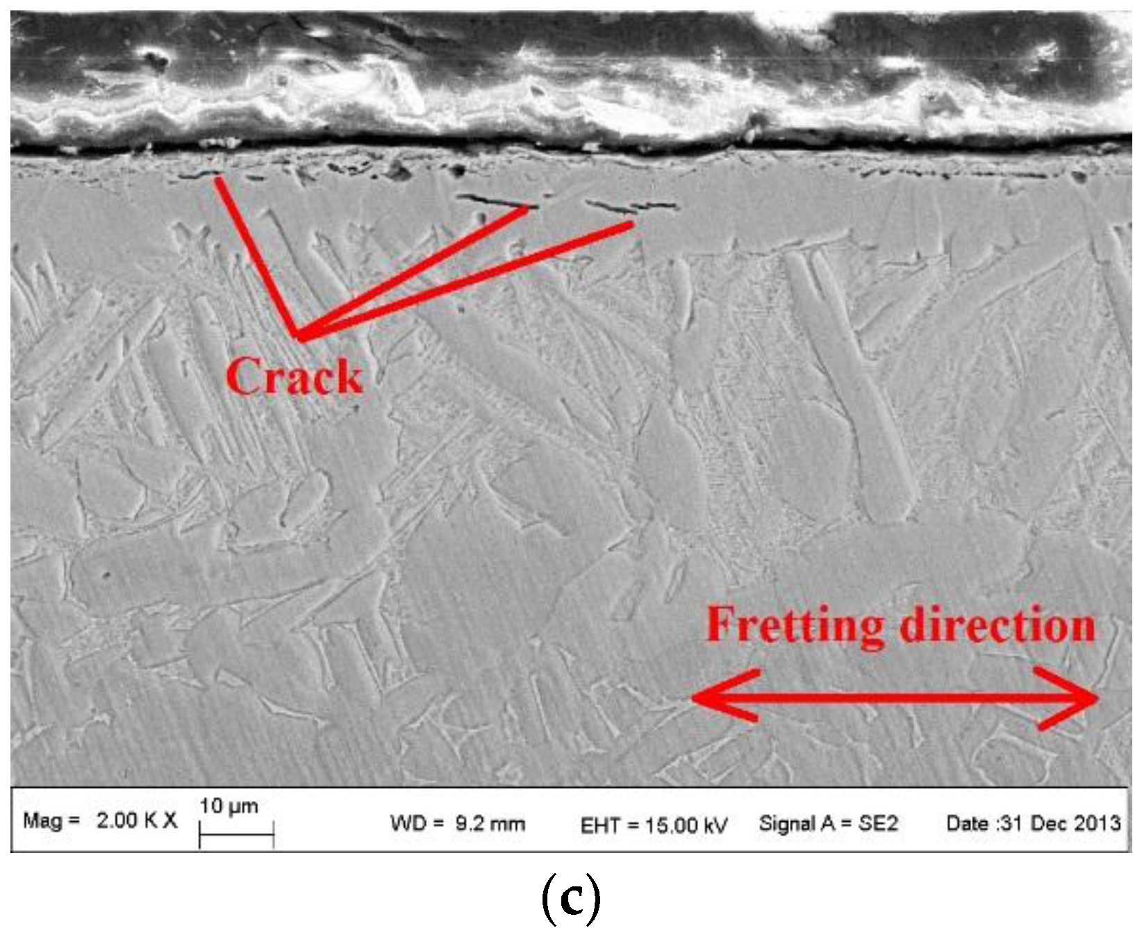
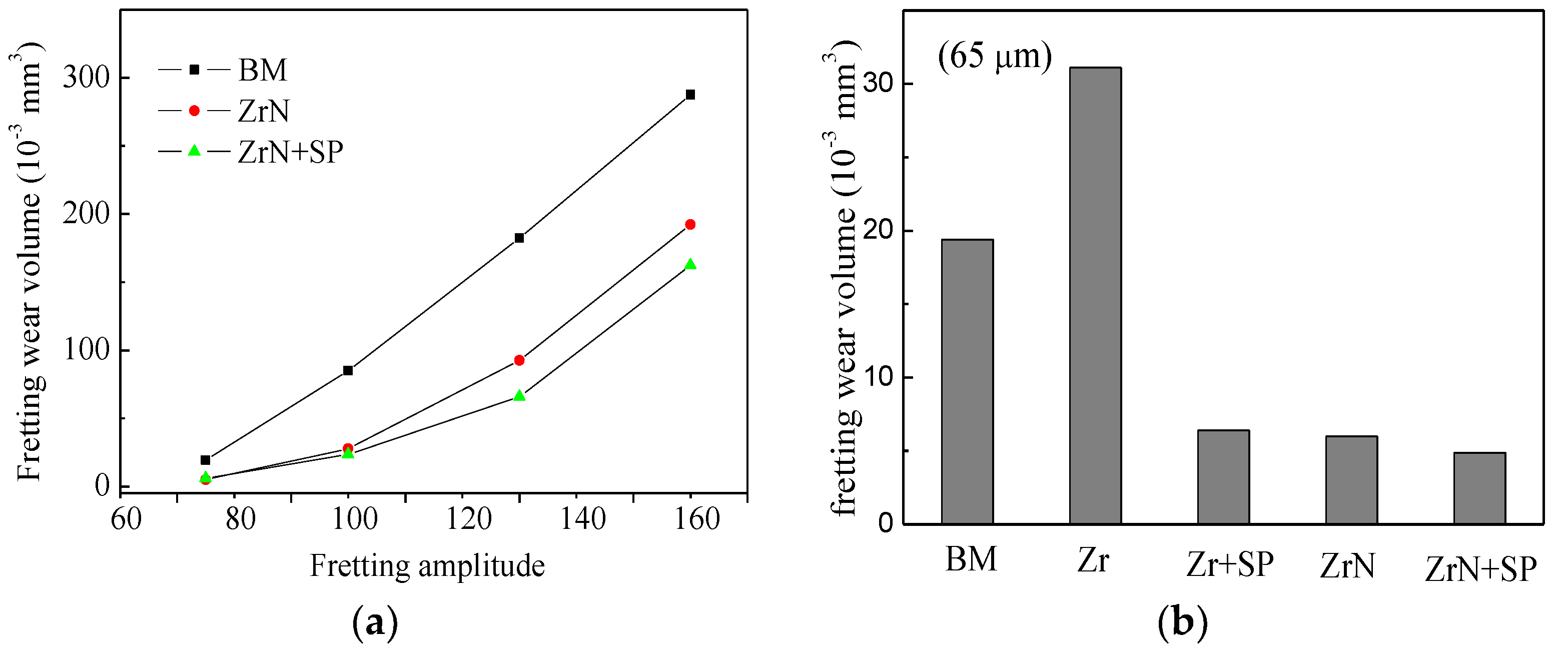
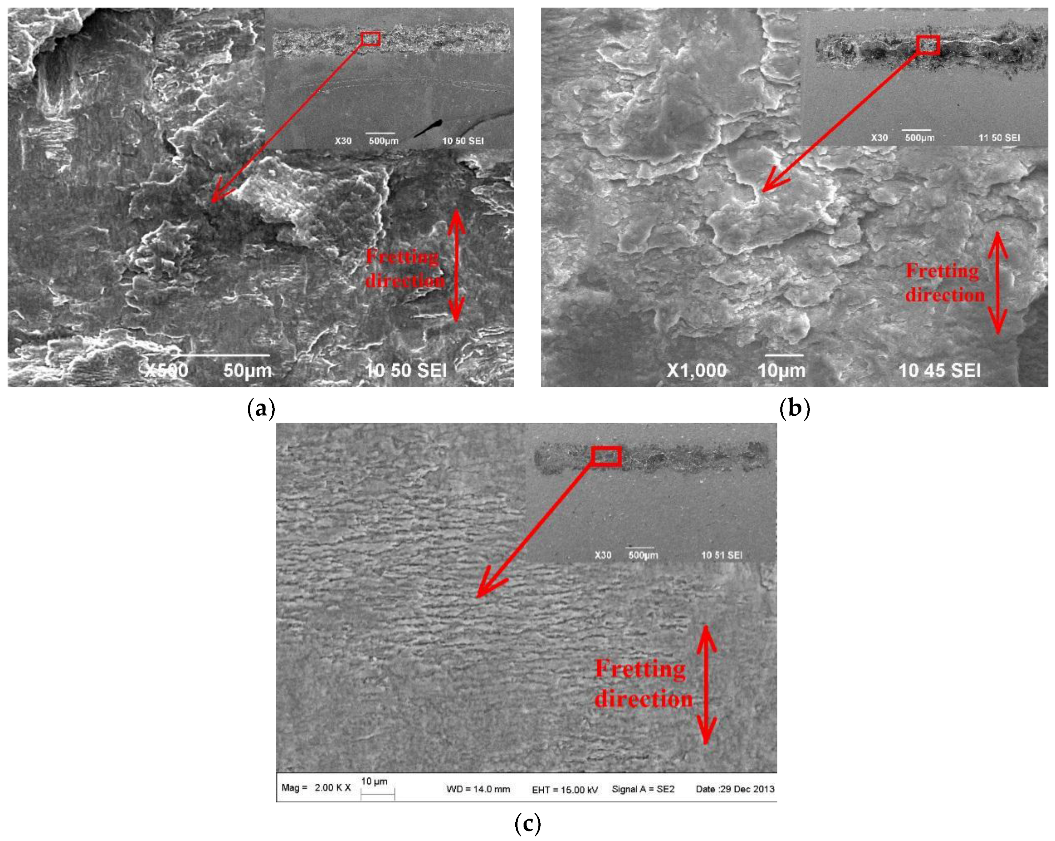
3.5. FW Behavior
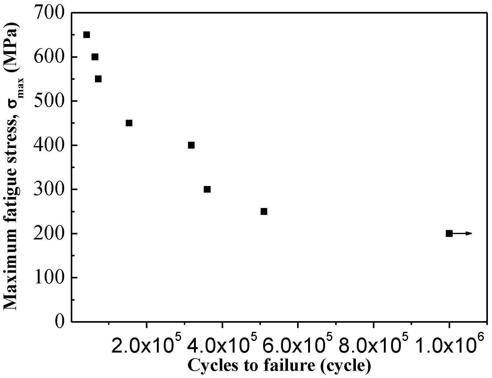
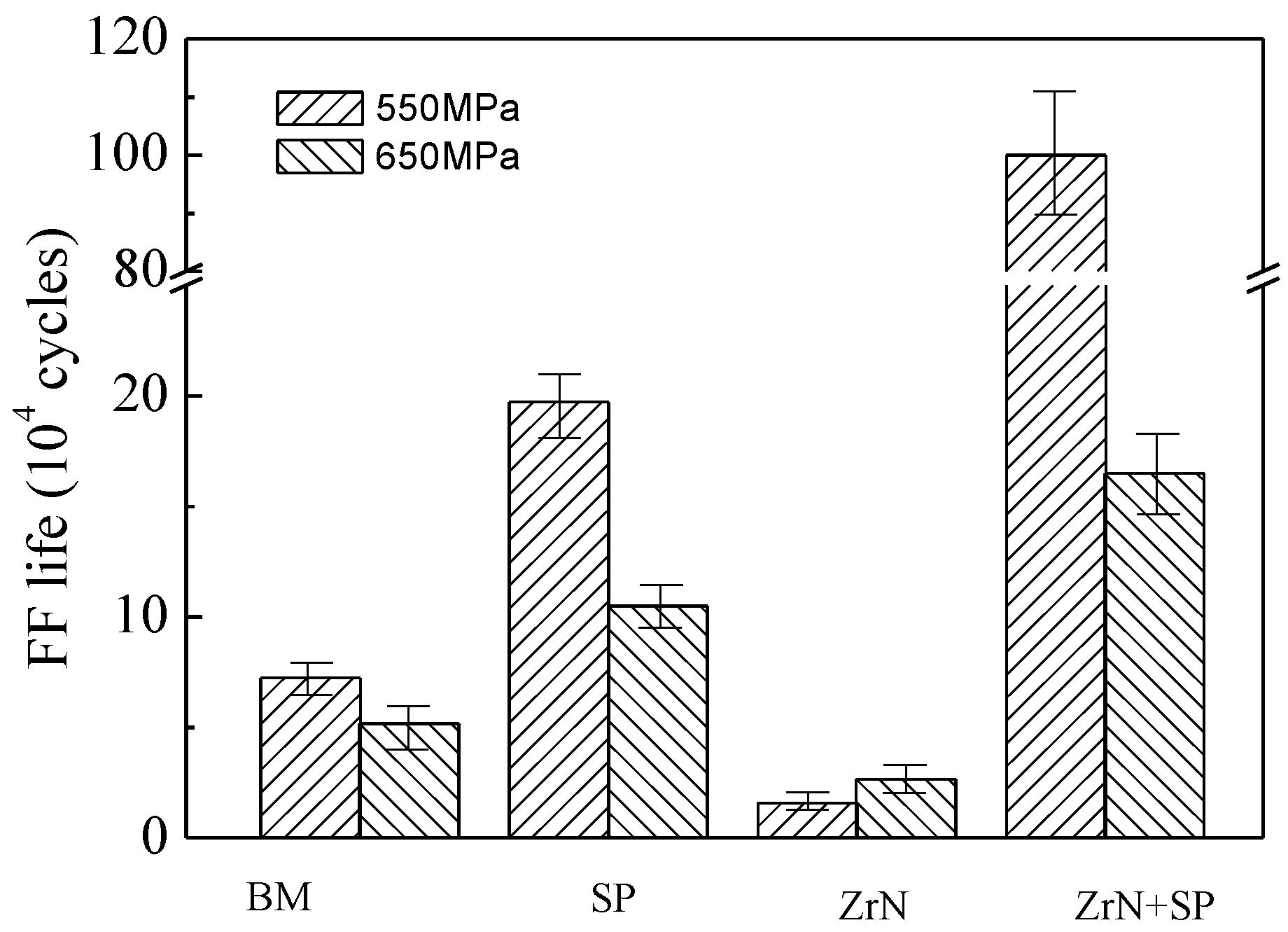
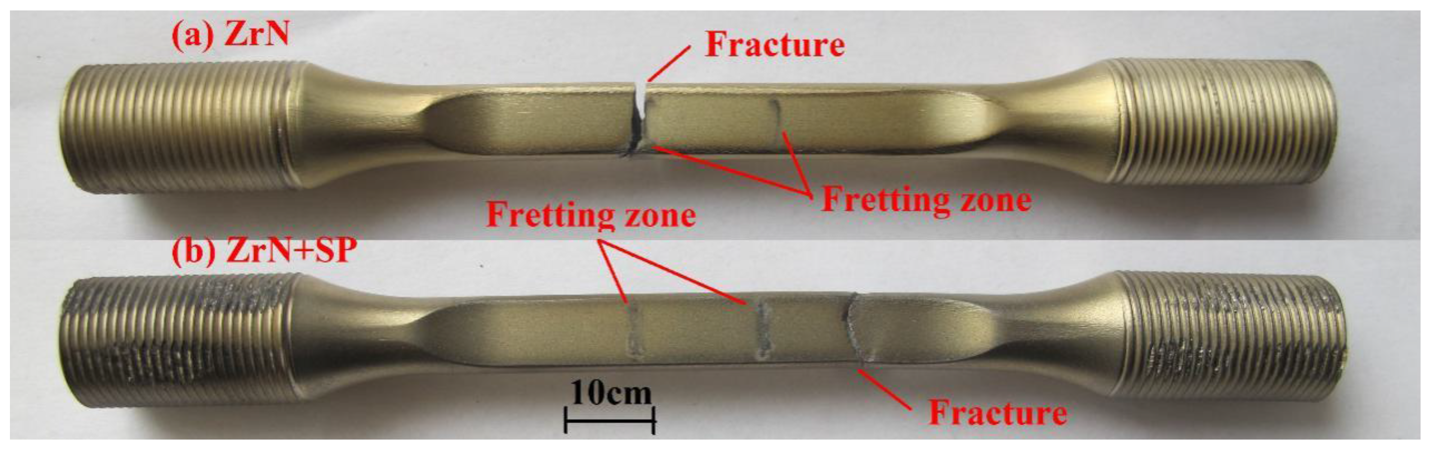
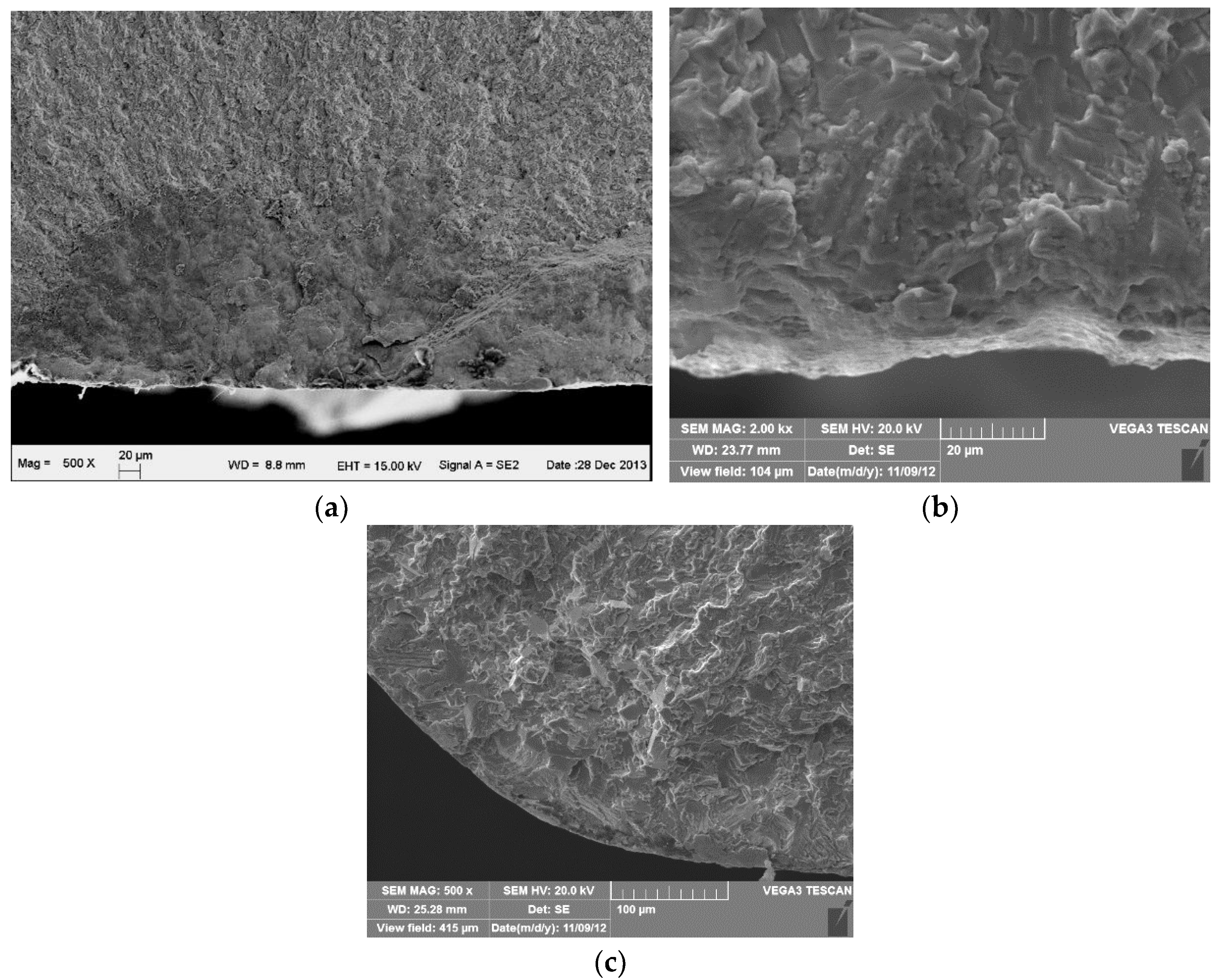
3.6. FF Behavior
4. Discussion
5. Conclusions
Acknowledgments
Author Contributions
Conflicts of Interest
References
- Mall, S.; Kim, H.K.; Saladin, E.C.; Porter, W.J. Effects of microstructure on fretting fatigue behavior of IN100. Mater. Sci. Eng. A 2010, 527, 1453–1460. [Google Scholar] [CrossRef]
- Nowell, D.; Dini, D.; Hills, D.A. Recent developments in the understanding of fretting fatigue. Eng. Fract. Mech. 2006, 73, 207–222. [Google Scholar] [CrossRef]
- Koul, A.K.; Bibby, M. An investigation on surface treatments for improving the fatigue resistance of titanium alloys. In Proceedings of the 82nd Meeting of the AGARD SMP on Tribology for Aerospace Systems, Swsimbra, Portugal, 6–7 May 1996.
- Ren, W.J.; Mall, S.; Sanders, J.H.; Sharma, S.K. Evaluation of coatings on Ti–6Al–4V substrate under fretting fatigue. Surf. Coat. Technol. 2005, 192, 177–188. [Google Scholar] [CrossRef]
- Yildiz, F.; Yetim, A.F.; Alsaran, A.; Çelik, A.; Kaymaz, I.; Efeoglu, I. Plain and fretting fatigue behavior of Ti6Al4V alloy coated with TiAlN thin film. Trib. Int. 2013, 66, 307–314. [Google Scholar] [CrossRef]
- Liu, D.X.; Tang, B.; Zhu, X.D.; Chen, H.; He, J.W.; Celis, J.P. Improvement of the fretting fatigue and fretting wear of Ti6Al4V by duplex surface modification. Surf. Coat. Technol. 1999, 116, 234–238. [Google Scholar] [CrossRef]
- Golden, P.J.; Hutson, A.; Sundaram, V.N.; Arps, J.H. Effect of surface treatments on fretting fatigue of Ti–6Al–4V. Int. J. Fatigue 2007, 29, 1302–1310. [Google Scholar] [CrossRef]
- Zhang, X.H.; Liu, D.X.; Liu, G.H.; Wang, Z.Y.; Tang, B. Improvement of the fretting damage resistance of Ti-811 alloy by CuNi multilayer film. Trib. Int. 2011, 44, 1488–1494. [Google Scholar] [CrossRef]
- Zhang, X.H.; Liu, D.X.; Tan, H.B.; Wang, X.F. Effect of TiN/Ti composite coating and shot peening on fretting fatigue behavior of TC17 alloy at 350 °C. Surf. Coat. Technol. 2009, 203, 2315–2321. [Google Scholar] [CrossRef]
- Vadiraj, A.; Kamaraj, M. Effect of surface treatments on fretting fatigue damage of biomedical titanium alloys. Trib. Int. 2007, 40, 82–88. [Google Scholar] [CrossRef]
- Rajasekaran, B.; Raman, S.G.S.; Joshi, S.V.; Sundararajan, G. Performance of plasma sprayed and detonation gun sprayed Cu–Ni–In coatings on Ti–6Al–4V under plain fatigue and fretting fatigue loading. Mater. Sci. Eng. A 2008, 479, 83–92. [Google Scholar] [CrossRef]
- Baradaran, S.; Zalnezhad, E.; Basirun, W.J.; Hamouda, A.M.S.; Sookhakian, M.; Sarhan, A.A.D.; Alias, Y. Statistical optimization and fretting fatigue study of Zr/ZrO2 nanotubular array coating on Ti–6Al–4V. Surf. Coat. Technol. 2014, 258, 979–990. [Google Scholar] [CrossRef]
- Liu, D.X.; Chen, H.; He, J.W. The effect of plasma nitriding and shot peening on the fretting damage resistance of Ti alloy. Trans. Mater. Heat Treat. 2001, 22, 49–54. (In Chinese) [Google Scholar]
- Liu, D.X.; He, J.W. Comparative study on the fretting fatigue and fretting wear behaviors of titanium alloy subjected to various surface modifications. Tribology 2005, 25, 13–17. (In Chinese) [Google Scholar]
- Murthy, H.; Mseis, G.; Farris, T.N. Life estimation of Ti–6Al–4V specimens subjected to fretting fatigue and effects of surface treatments. Trib. Int. 2009, 42, 1304–1315. [Google Scholar] [CrossRef]
- Zhang, X.H.; Liu, D.X. Effect of shot peening on fretting fatigue of Ti811 alloy at elevated temperature. Int. J. Fatigue 2009, 31, 889–893. [Google Scholar] [CrossRef]
- Liu, K.K.; Hill, M.R. The effects of laser peening and shot peening on fretting fatigue in Ti–6Al–4V coupons. Trib. Int. 2009, 42, 1250–1262. [Google Scholar] [CrossRef]
- Deng, J.X.; Liu, J.H.; Ding, Z.L.; Niu, M. Unlubricated friction and wear behaviors of ZrN coatings against hardened steel. Mater. Des. 2008, 29, 828–1834. [Google Scholar] [CrossRef]
- Tang, J.G.; Liu, D.X.; Tang, C.B.; Yu, S.M.; Zhang, X.H. Tribology behavior of Zr-N alloying layer on Ti6Al4V alloy surface at elevated temperature. Rare Met. Mater. Eng. 2013, 42, 331–335. (In Chinese) [Google Scholar]
- Liu, A.S. Binary Alloy Phase Diagrams; Metallurgy Press: Beijing, China, 2002. (In Chinese) [Google Scholar]
- Du, D.X.; Liu, D.X.; Ye, Z.Y.; Zhang, X.H.; Li, F.Q.; Zhou, Z.Q.; Yu, L. Fretting wear and fretting fatigue behaviors of diamond-like carbon and graphite like carbon films deposited on Ti-6Al-4V alloy. Appl. Surf. Sci. 2014, 313, 462–469. [Google Scholar] [CrossRef]
- Kubiak, K.; Fouvry, S.; Marechal, A.M.; Vernet, J.M. Behaviour of shot peening combined with WC–Co HVOF coating under complex fretting wear and fretting fatigue loading conditions. Surf. Coat. Technol. 2006, 201, 4323–4328. [Google Scholar] [CrossRef]


© 2016 by the authors; licensee MDPI, Basel, Switzerland. This article is an open access article distributed under the terms and conditions of the Creative Commons by Attribution (CC-BY) license (http://creativecommons.org/licenses/by/4.0/).
Share and Cite
Tang, J.; Liu, D.; Zhang, X.; Du, D.; Yu, S. Effects of Plasma ZrN Metallurgy and Shot Peening Duplex Treatment on Fretting Wear and Fretting Fatigue Behavior of Ti6Al4V Alloy. Materials 2016, 9, 217. https://doi.org/10.3390/ma9040217
Tang J, Liu D, Zhang X, Du D, Yu S. Effects of Plasma ZrN Metallurgy and Shot Peening Duplex Treatment on Fretting Wear and Fretting Fatigue Behavior of Ti6Al4V Alloy. Materials. 2016; 9(4):217. https://doi.org/10.3390/ma9040217
Chicago/Turabian StyleTang, Jingang, Daoxin Liu, Xiaohua Zhang, Dongxing Du, and Shouming Yu. 2016. "Effects of Plasma ZrN Metallurgy and Shot Peening Duplex Treatment on Fretting Wear and Fretting Fatigue Behavior of Ti6Al4V Alloy" Materials 9, no. 4: 217. https://doi.org/10.3390/ma9040217